JP3731021B2 - Position detection surveying instrument - Google Patents
Position detection surveying instrument Download PDFInfo
- Publication number
- JP3731021B2 JP3731021B2 JP03321797A JP3321797A JP3731021B2 JP 3731021 B2 JP3731021 B2 JP 3731021B2 JP 03321797 A JP03321797 A JP 03321797A JP 3321797 A JP3321797 A JP 3321797A JP 3731021 B2 JP3731021 B2 JP 3731021B2
- Authority
- JP
- Japan
- Prior art keywords
- light
- target
- surveying instrument
- light receiving
- unit
- Prior art date
- Legal status (The legal status is an assumption and is not a legal conclusion. Google has not performed a legal analysis and makes no representation as to the accuracy of the status listed.)
- Expired - Fee Related
Links
Images


Classifications
-
- G—PHYSICS
- G01—MEASURING; TESTING
- G01C—MEASURING DISTANCES, LEVELS OR BEARINGS; SURVEYING; NAVIGATION; GYROSCOPIC INSTRUMENTS; PHOTOGRAMMETRY OR VIDEOGRAMMETRY
- G01C15/00—Surveying instruments or accessories not provided for in groups G01C1/00 - G01C13/00
- G01C15/002—Active optical surveying means
Description
【0001】
【発明の属する技術分野】
本発明は、ターゲットの位置を検出するための位置検出測量機に係わり、特に、自動測量装置に最適であり、高価な音響光学素子を使用することなく、省電力、小型化が可能な位置検出測量機に関するものである。
【0002】
【従来の技術】
近年、ターゲットの位置を検出することのできる自動測量装置が開発され、測量のワンマン化が進んでいる。この自動測量装置は、走査部や、測距部、測角部等を備えており、本体を水平方向に回転させるための駆動手段や、鏡筒を垂直回転させるための駆動手段等から構成されていた。
【0003】
ターゲットに設けられているプリズムの検出には、走査部からターゲットに向けて射出された光の反射光を利用しており、受光された反射光を受光部で、受光信号に変換し、回転手段や駆動手段にフィードバック制御することにより、自動測量装置をターゲットの方向に向ける構成となっている。
【0004】
走査部から射出されたレーザー光は、音響光学素子により、水平方向、及び垂直方向に偏向され、射出方向の特定の部分を例えば、リサージュ走査する様になっている。
【0005】
ここで、図15に基づいて、音響光学素子を利用した偏向手段について説明する。
【0006】
レーザーダイオード21は、走査光として赤外レーザー光を出射し、コリメータレンズにより平行光束に変換される。水平偏向素子23と垂直偏向素子24とが、音響光学素子であり、水平偏向素子23は赤外レーザーを水平方向Hに偏向させ、垂直偏向素子24は、赤外レーザー光を垂直方向Vに偏向させる様になっている。
【0007】
【発明が解決しようとする課題】
しかしながら、上記音響光学素子を利用した偏向手段は、非常に高価でコストアップの原因となる上、発熱を伴うので、消費電力が増大し、小型電池による駆動が事実上困難となるという問題点があった。
【0008】
従って、ライン電源や、大型のバッテリーパックを持参する必要があり、携帯性に劣る上、測量の作業効率も低下するという深刻な問題点があった。
【0009】
更に音響光学素子は、偏向角に限界があり、走査範囲を広げるためには、鏡筒を鉛直方向に回転させる必要があるという問題点があった。
【0010】
【課題を解決するための手段】
本発明は上記課題に鑑み案出されたもので、装置本体を水平回転させ鏡筒を垂直回転させてターゲットの位置を検出するための位置検出測量機において、前記鏡筒は、光波距離計と、前記ターゲットに向けて上下方向に扇状光を照射するための発光部と、前記ターゲットからの反射光を検出する受光部とを備え、この受光部が前記ターゲットからの反射光を検出することにより、前記装置本体の水平回転を前記ターゲットに向けて停止させ、前記光波距離計が前記ターゲットからの反射光を検出することにより、前記鏡筒の垂直回転を前記ターゲットに向けて停止させるための演算処理手段とからなる位置検出測量機。
【0011】
また本発明の受光部は、発光部を挟んで水平方向に一対の受光部が配置され、装置本体の水平回転方向と一対の受光部のどちらが先に受光されたかによって、ターゲットであるか、不要反射体であるかを識別する構成にすることもできる。
【0012】
更に本発明の発光部の扇状光は、ポインタービームに切り替え可能であって、水平回転と垂直回転を、ターゲットに向けて停止させた後、扇状光からポインタービームに切り替えて、前記ターゲットに向けてポインタービームを投射する構成にすることもできる。
【0016】
【発明の実施の形態】
以上の様に構成された本発明は、装置本体を水平回転させ鏡筒を垂直回転させてターゲットの位置を検出するための位置検出測量機であって、発光部が、ターゲットに向けて上下方向に扇状光を照射させ、受光部が、ターゲットからの反射光を検出する様になっており、演算処理手段が、受光部がターゲットからの反射光を検出することにより、装置本体の水平回転をターゲットに向けて停止させ、光波距離計がターゲットからの反射光を検出することにより、鏡筒の垂直回転をターゲットに向けて停止させることができる。
【0017】
また本発明の受光部は、発光部を挟んで水平方向に一対の受光部が配置され、装置本体の水平回転方向と一対の受光部のどちらが先に受光されたかによって、ターゲットであるか、不要反射体であるかを識別することもできる。
【0018】
更に本発明の発光部の扇状光は、ポインタービームに切り替え可能であって、水平回転と垂直回転を、ターゲットに向けて停止させた後、扇状光からポインタービームに切り替えて、ターゲットに向けてポインタービームを投射することもできる。
【0021】
【実施例】
【0022】
「原理」
【0023】
まず、本発明の「上下方向に扇状となる光」を照射させる発光手段100の原理を図13(a)及び図13(b)に基づいて説明する。
【0024】
発光手段100は、図13(a)及び図13(b)に示す様に、光源110と、コリメートレンズ120と、シリンドリカルレンズ130とから構成されている。
【0025】
光源110はレーザー光源を発生させるもので、本実施例では、レーザーダイオードが採用されている。
【0026】
コリメートレンズ120は、光源110からのレーザー光を平行光束に変換するためのものである。
【0027】
シリンドリカルレンズ130は、図13(a)に示す様に、側面から見ると1面が凸レンズとなっているものか、或いは、図13(b)に示す様に側面から見ると、1面が凹レンズとなっているものを使用することができる。
【0028】
従って、図13(a)に示す様に、シリンドリカルレンズ130に平行光束を入射させると、焦点距離Fで集光されるが、焦点距離Fより離れた位置では、上下方向に扇状となる光となる。
【0029】
また、図13(b)に示す様に、シリンドリカルレンズ130に平行光束を入射させると、上下方向に扇状となる光が射出される。
【0030】
「第1実施例」
【0031】
本発明の第1実施例を図面に基づいて説明する。
【0032】
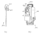
図1(a)は、本第1実施例の自動測量機1000を示す斜視図であり、自動測量機1000は、自動測量機本体1100と、発光手段100と、受光手段200と、光波距離計300と、鏡筒400とから構成されている。
【0033】
本第1実施例では、光波距離計300と視準望遠鏡が同軸に構成されている。
【0034】
発光手段100は、図1(b)に示すターゲット2000のプリズム2100を検知するために照射するものである。本実施例の発光手段100は、上述した「原理」で説明した様に、「上下方向に扇状となる光」を照射させるものであれば、何れのものを使用することができる。
【0035】
受光手段200は、ターゲット2000のプリズム2100で反射された反射光を受光するためのものである。反射光を電気信号に変換することのできる素子であれば、何れの素子を利用することができる。
【0036】
光波距離計300は、ターゲット2000までの距離を測定するための距離測定手段に該当するものである。例えば、本実施例の光波距離計300は、位相差測定方式又はパルス測定方式を利用した距離計等を使用することができる。
【0037】
ここで図14に基づいて、光波距離計300の一例を説明する。
【0038】
光波距離計300は、測距光を出射方向に向けて反射させるためのプリズム2100と、測距光を発光させるための発光部310と、プリズム2100からの反射光を受光するための受光部320と、発光部310からの測距光をプリズム2100に向けて反射させると共に、プリズム2100からの反射光を受光部320に向けるためのミラー330と、測距光をコリメートして反射光を受光部320に合焦させるための対物レンズ340とを備えている。
【0039】
光波距離計300は、位相差測定による距離測定装置であり、発光部310と受光部320とを備えている。そして受光部は、受光部からの光量を捕らえることは容易に行うことができる。
【0040】
鏡筒400は、鉛直方向に回動可能に構成されており、発光手段100と受光手段200と光波距離計300とが取り付けられている。
【0041】
次に図4に基づいて、本第1実施例の自動測量機1000の電気的構成を説明する。
【0042】
本第1実施例の自動測量機1000は、レーザーダイオード110と、レーザーダイオード駆動部111と、受光部200と、光波距離計300と、同期検出回路500と、クロック回路600と、信号処理部700と、制御部800と、回転駆動部900とから構成されている。
【0043】
レーザーダイオード110とレーザーダイオード駆動部111とは、発光手段100を構成するもので、レーザーダイオード駆動部111が、クロック回路600のクロック信号に基づき、レーザーダイオード110を駆動し、レーザー光を発生する様になっている。
【0044】
同期検出回路500は、クロック回路600のクロック信号に基づき、受光部200の受光信号から反射レーザー光の受光信号を検出するための同期検波のための回路である。
【0045】
クロック回路600は、同期検出回路500が同期検波するためのタイミング及びレーザーダイオード駆動部111を駆動するタイミングを決定するクロック信号を形成するためのものである。
【0046】
信号処理部700は、波形整形等の信号処理を行うためのものである。
【0047】
制御手段800は、演算処理手段に該当するもので、CPUを含み、全体の制御を司ると共に、角度の決定等の各種演算等を行うためのものである。
【0048】
信号処理部700からの処理信号に基づいて制御手段800は演算を行い、自動測量機本体1100をプリズム2100に向ける様にフィードバック制御を行う。
【0049】
回転駆動部900は、自動測量機本体1100を水平方向に回転させるための制御を行うためのものである。
【0050】
ここで、図5に基づいて、自動測量機本体1100を水平方向及び鉛直方向に回転させるための機構を説明する。なお、この機構が回動手段に該当するものである。
【0051】
この自動測量機1000は、図5に示す様に、固定台4と、この固定台4に取り付けられた基台5とを備えている。基台5はその平面5aと固定台4の平面4aとのなす角度がレベリングスクリューS、S、Sによって調整できる様になっている。
【0052】
基台5には、鉛直方向に延びた軸受部6を有する軸受部材7が固定され、この軸受部材7には鉛直方向に延びた回転軸8が回転自在に取り付けられている。回転軸8には測量機本体1100が取り付けられていて、回転軸8と共に測量機本体1100が基台5に対して水平方向に回転可能に構成されている。測量機本体1100には、高低角を微調整するための調整ノブと水平角を調整するための調整ノブが設けられている。
【0053】
測量機本体1100は、両方から上方へ膨出した2つの膨出部51、52が形成されており、この膨出部51、52の間の凹部53には鏡筒400が配置されている。この鏡筒400の側板61、62には水平方向に延びた水平軸63、64が設けられており、この水平軸63、64が膨出部61、62の側板65、66に軸受67、68を介して回転可能に保持されていて鏡筒部400が鉛直方向に回転できる様に構成されている。
【0054】
測量機本体1100の回転は、測量機本体1100内に設けたモータ70によって行なうもので、このモータ70は測量機本体1100の側板71に取り付けられている。モータ70の駆動軸72にはギア73が設けられており、ギア73は軸受部6に固定された平歯車74に噛合している。平歯車74は回転軸8と同心状となっている。これにより、モータ70の駆動によって平歯車74の回りをギア73が回転移動していき、測量機本体1100が回転軸8と共に回転することになる。
【0055】
回転軸8の上部には水平角目盛用目盛板75が取り付けられており、その水平角目盛を読む水平角読取エンコーダ76が平歯車74に設けられている。水平角読取エンコーダ76は水平角目盛用目盛板75が微小角回転する毎にパルスを発生させるためのものである。
【0056】
鏡筒部400の回転は、膨出部52に設けたモータ80によって行うもので、このモータ80の駆動軸81にはギア82が設けられており、ギア82は水平軸64に固定した平歯車83に噛合している。これにより、モータ80の駆動によって、平歯車83が回転して水平軸63、64が鏡筒部400と共に回転する。
【0057】
水平軸63には、高低角目盛用目盛板84が取り付けられており、高低角目盛を読む高低角読取用エンコーダ85が膨出部51に設けられている。高低角読取用エンコーダ85は、高低角目盛用目盛板84が微小角回転する毎にパルスを発生させるためのものである。
【0058】
次に本第1実施例の動作を図6に基づいて具体的に説明する。
【0059】
初めに、図7に示す様に、自動測量機1000を三脚上に配置する。
【0060】
まずステップ1(以下S1と略する。)で、電源を投入し、測定を開始する。S2では、レーザーダイオード駆動部111が、クロック回路600のタイミング信号に基づき、レーザーダイオード110を駆動し、シリンドリカルレンズ130から上下方向に扇状となる光(上下ファンビーム)が射出される。
【0061】
そしてS3では、制御手段800が回転駆動部900を制御駆動し、モータ70を回転させて測量機本体1100を水平方向に回転させる。
【0062】
次にS4では、制御手段800が、ターゲット2000からの反射光が、受光部200で検出されるかを判断する。シリンドリカルレンズ130から上下方向に扇状となる光(上下ファンビーム)が射出されているので、ターゲット2000のプリズム2100と相対する位置になった場合には、プリズム2100に入射した光が反射され、反射光が、受光部200に入射される。
【0063】
受光部200に反射光が入射されると、受光信号は、信号処理部700で波形整形等の信号処理が施された後、制御手段800に入力される。そして制御手段800が、反射光の入力を認識した場合には、S5に進み、S5では、制御手段800が回転駆動部900を制御し、モータ70の回転を停止させて測量機本体1100の回転を中止させ、水平角を決定する。
【0064】
またS4で、制御手段800が、受光部200に反射光の入射を認識しない場合には、S3に戻り、測量機本体1100の水平方向の回転を継続させる。
【0065】
S5で、測量機本体1100の回転を中止させた後、S6に進む。S6では、制御手段800が光波距離計300を駆動させる。そしてS7では、制御手段800が回転駆動部900を制御駆動し、モータ80を回転させて鏡筒400を鉛直方向に回転させる。
【0066】
次にS8では、制御手段800が、光波距離計300で反射光検出が行われたか否かを判断する。そしてS8で反射光の検出を認識した場合には、S9に進み、S9では、制御手段800が回転駆動部900を制御し、モータ80の回転を停止させて鏡筒400の回転を中止させる。
【0067】
そして、図9に示す様に、光波距離計300の反射光量とエンコーダ85に基づく角度位置から重心を演算し、この重心位置から高度角を検出する。
【0068】
なおS8で、光波距離計300の反射光検出が認められない場合には、S7に戻り、鏡筒400の鉛直方向の回転を継続させる。
【0069】
S5で水平角を、S9で鉛直角を決定した後、S10に進み、シリンドリカルレンズ130を切り替えて外し、ポインタービームを出力させる。そしてS11で、光波距離計300による測距を行う。
【0070】
ポインタービームは、ターゲット2000のターゲット板2200の中心に投射され、測量機本体1100がプリズム2100に相対したことが判る。
【0071】
以上の様に構成された本第1実施例は、自動的に自動測量機1000をターゲット2000のプリズム2100に向けるて位置決めすることができる。
【0072】
なお、光波距離計300は、自動測量機1000に初めから装備されていてもよいが、従来の光波距離計300に対して、本第1実施例の構成を付加させるタイプのものであってもよい。
【0073】
また本第1実施例は、本発明の位置検出装置を自動測量機1000に応用したものであるが、自動測量機1000に限ることなく、何れの測量装置に応用することができる。
【0074】
更に、光波距離計300の光ビームは、5分から7分程度の広がりを有するので、更に、光波距離計300の光ビームを利用して、上述した原理により、正確な位置決めを行うこともできる。
【0075】
「第2実施例」
【0076】
本発明の第2実施例を図面に基づいて説明する。
【0077】
図2(a)は、本第2実施例の自動測量機1000を示す斜視図であり、自動測量機1000は、自動測量機本体1100と、発光手段100と、第1の受光部200Aと、第2の受光部200Bと、光波距離計300と、鏡筒400とから構成されている。
【0078】
本第2実施例では、光波距離計300と視準望遠鏡が同軸に構成されている。
【0079】
発光手段100は、図2(b)に示すターゲット2000のプリズム2100に向けて光を照射させるためのものである。本実施例の発光手段100は、上述した「原理」で説明した様に、「上下方向に扇状となる光」を照射させるものであれば、何れのものを使用することができる。
【0080】
受光手段200は、ターゲット2000のプリズム2100で反射された反射光を受光するためのものである。反射光を電気信号に変換することのできる素子であれば、何れの素子を利用することができる。
【0081】
本第2実施例の受光手段200は、図3(a)及び図3(b)に示す様に、発光手段100を挟んで1対配置されている。即ち、受光手段200は、第1の受光部200Aと第2の受光部200Bとから構成されている。
【0082】
ここで、図3(a)に示す様に、自動測量機本体1100が反時計回りに回転した場合のプリズム2100からの受光状態を示し、図3(b)は同様に反時計回りした場合の不要反射面からの受光状態を示している。
【0083】
再帰反射部材であるプリズム2100で反射された反射光は、第2の受光手段200Bより先に第1の受光手段200Aに入射する。
【0084】
図3(b)の様な不要反射面、例えば、相対するミラー等で反射された場合には、先に第2の受光手段200Bに入射する。
【0085】
自動測量機本体1000が時計回りをした場合、プリズム2100で反射された反射光は、先に第2の受光部200Bに入射し、不要反射面で反射された反射光は、先に第1の受光部200Aに入射する。
【0086】
従って反射光が、第1の受光部200A及び第2の受光部200Bのどちらが先に入射したことを認識することにより、不要反射を識別することができる。
【0087】
次に図9に基づいて、本第2実施例の自動測量機1000の電気的構成を説明する。
【0088】
本第2実施例の自動測量機1000は、レーザーダイオード110と、レーザーダイオード駆動部111と、第1の受光部200Aと第2の受光部200Bと、光波距離計300と、同期検出回路500と、クロック回路600と、信号処理部700と、制御部800と、回転駆動部900とから構成されている。
【0089】
レーザーダイオード110とレーザーダイオード駆動部111とは、発光手段100を構成するもので、レーザーダイオード駆動部111が、クロック回路600のクロック信号に基づき、レーザーダイオード110を駆動し、レーザー光を発生する様になっている。
【0090】
同期検出回路500は、クロック回路600のクロック信号に基づき、第1の受光部200Aと第2の受光部200Bの受光信号から反射レーザー光の受光信号を検出するための同期検波のための回路である。
【0091】
クロック回路600は、同期検出回路500が同期検波するためのタイミング及びレーザーダイオード駆動部111を駆動するタイミングを決定するクロック信号を形成するためのものである。
【0092】
信号処理部700は、第1の受光部200Aと第2の受光部200Bの差を取ると共に、波形整形等の信号処理を行うためのものである。
【0093】
制御手段800は、演算処理手段に該当するもので、CPUを含み、全体の制御を司ると共に、角度の決定等の各種演算等を行うためのものである。
【0094】
信号処理部700からの処理信号に基づいて制御手段800は演算を行い、自動測量機本体1100をプリズム2100に向ける様にフィードバック制御を行う。
【0095】
回転駆動部900は、自動測量機本体1100を水平方向に回転させるための制御を行うためのものである。
【0096】
次に本第2実施例の動作を図10に基づいて具体的に説明する。
【0097】
初めに、図7に示す様に、自動測量機1000を三脚上に配置する。
【0098】
まずステップ1(以下S1と略する。)で、電源を投入し、測定を開始する。S2では、レーザーダイオード駆動部111が、クロック回路600のタイミング信号に基づき、レーザーダイオード110を駆動し、シリンドリカルレンズ130から上下方向に扇状となる光(上下ファンビーム)が射出される。
【0099】
そしてS3では、制御手段800が回転駆動部900を制御駆動し、モータ70を回転させて測量機本体1100を水平方向に回転させる。
【0100】
次にS4では、制御手段800が、ターゲット2000からの反射光が、第1の受光部200Aか又は第2の受光部200Bで検出されるかを判断する。シリンドリカルレンズ130から上下方向に扇状となる光(上下ファンビーム)が射出されているので、ターゲット2000のプリズム2100と相対する位置になるまでフィードバック制御される。
【0101】
第1の受光部200Aか又は第2の受光部200Bに反射光が入射されると、受光信号は、信号処理部700で波形整形等の信号処理が施された後、制御手段800に入力される。そして制御手段800が、反射光の入力をターゲットからの反射光であると認識した場合には、S5に進み、S5では、制御手段800が回転駆動部900を制御し、モータ70の回転を停止させて測量機本体1100の回転を中止させ、水平角を決定する。なお、不要反射であると判断した場合には、S5に進まず回転を継続する。
【0102】
またS4で、制御手段800が、反射光の入射を認識しない場合には、S3に戻り、測量機本体1100の水平方向の回転を継続させる。
【0103】
S5で、測量機本体1100の回転を中止させた後、S6に進む。S6では、制御手段800が光波距離計300を駆動させる。そしてS7では、制御手段800が回転駆動部900を制御駆動し、モータ80を回転させて鏡筒400を鉛直方向に回転させる。
【0104】
次にS8では、制御手段800が、光波距離計300で反射光検出が行われたか否かを判断する。そしてS8で反射光の検出を認識した場合には、S9に進み、S9では、制御手段800が回転駆動部900を制御し、モータ80の回転を停止させて鏡筒400の回転を中止させる。
【0105】
そして、図8に示す様に、光波距離計300の反射光量とエンコーダ85に基づく角度位置から重心を演算し、この重心位置から高度角を検出する。
【0106】
なおS8で、光波距離計300の反射光検出が認められない場合には、S7に戻り、鏡筒400の鉛直方向の回転を継続させる。
【0107】
S5で水平角を、S9で鉛直角を決定した後、S10に進み、シリンドリカルレンズ130を切り替えて外し、ポインタービームを出力させる。そしてS11で、光波距離計300による測距を行う。
【0108】
ポインタービームは、ターゲット2000のターゲット板2200の中心に投射され、測量機本体1100がプリズム2100に相対したことが判る。
【0109】
以上の様に構成された本第2実施例は、自動的に自動測量機1000をターゲット2000のプリズム2100に向けて位置決めすることができる。
【0110】
なお、本第2実施例のその他の構成、作用は、第1実施例と同様であるから説明を省略する。
【0111】
「第3実施例」
【0112】
本発明の第3実施例を説明する。
【0113】
上述の第1実施例又は第2実施例は、「上下方向に扇状となる光」をターゲット2000に向けて照射し、この反射光から水平角を決定し、鉛直角は、光波距離計の光を利用し、光波距離計の反射光の重心位置を利用して鉛直角を求めていた。
【0114】
本第3実施例は、光波距離計の光を利用せず、第1実施例及び第2実施例の水平角を決定する方法を鉛直角に応用したものである。
【0115】
次に図11に基づいて、本第3実施例の自動測量機1000の電気的構成を説明する。
【0116】
本第3実施例は、第1レーザーダイオード110と、第2のレーザーダイオード115と、第1のレーザーダイオード駆動部111と、第2のレーザーダイオード駆動部116と、第1の受光部200Aと第2の受光部200Bと、第3の受光部200Cと第4の受光部200Dと、光波距離計300と、同期検出回路500と、クロック回路600と、信号処理部700と、制御部800と、回転駆動部900とから構成されている。
【0117】
第1レーザーダイオード110は、第1の実施例と同様に、「上下方向に扇状となる光」を照射させる第1の発光手段100の構成の一つであって、第1のシリンドリカルレンズ130により、「上下方向に扇状となる光」を射出する様に構成されている。
【0118】
第2レーザーダイオード115は、「水平方向に扇状となる光」を照射させる第2の発光手段119の構成の一つであって、第2のシリンドリカルレンズ139により、「水平方向に扇状となる光」を射出する様に構成されている。
【0119】
即ち第2の発光手段119は、第1の発光手段100を90度回転させて配置し、「水平方向に扇状となる光」を射出させるものである。
【0120】
第1の受光部200Aと第2の受光部200Bは、第1の実施例と同様に、第1の発光手段100の第1レーザーダイオード110から射出された「上下方向に扇状となる光」の反射光を受光するためのものである。
【0121】
第3の受光部200Cと第4の受光部200Dは、第2の発光手段109の第2レーザーダイオード115から射出された「水平方向に扇状となる光」の反射光を受光するためのものである。
【0122】
第1のレーザーダイオード駆動部111は、第1実施例と同様に、第1レーザーダイオード110を駆動して、「上下方向に扇状となる光」を射出させるためのものである。
【0123】
第2のレーザーダイオード駆動部116は、第2レーザーダイオード115を駆動して、「水平方向に扇状となる光」を射出させるためのものである。
【0124】
以上の様に構成された第3実施例の自動測量機1000の動作を図12に基づいて具体的に説明する。
【0125】
まずステップ1(以下S1と略する。)で、電源を投入し、測定を開始する。S2では、第1のレーザーダイオード駆動部111が、クロック回路600のタイミング信号に基づき、第1レーザーダイオード110を駆動し、第1のシリンドリカルレンズ130から上下方向に扇状となる光(上下ファンビーム)が射出される。
【0126】
そしてS3では、制御手段800が回転駆動部900を制御駆動し、モータ70を回転させて測量機本体1100を水平方向に回転させる。
【0127】
次にS4では、制御手段800が、ターゲット2000からの反射光が、第1の受光部200Aか又は第2の受光部200Bで検出されるかを判断する。第1のシリンドリカルレンズ130から上下方向に扇状となる光(上下ファンビーム)が射出されているので、ターゲット2000のプリズム2100と相対する位置になるまでフィードバック制御される。
【0128】
第1の受光部200Aか又は第2の受光部200Bに反射光が入射されると、受光信号は、信号処理部700で波形整形等の信号処理が施された後、制御手段800に入力される。そして制御手段800が、反射光の入力をターゲット2000からの反射光であると認識した場合には、S5に進み、S5では、制御手段800が回転駆動部900を制御し、モータ70の回転を停止させて測量機本体1100の回転を中止させ、水平角を決定する。なお、第2の受光部200Bに反射光が入射された場合には、不要反射であると判断し、S5に進まず回転を継続する。
【0129】
またS4で、制御手段800が、反射光の入射を認識しない場合には、S3に戻り、測量機本体1100の水平方向の回転を継続させる。
【0130】
S5で、測量機本体1100の回転を中止させた後、S6に進む。S6では、第2のレーザーダイオード駆動部116が、クロック回路600のタイミング信号に基づき、第2レーザーダイオード115を駆動し、第2のシリンドリカルレンズ139から水平方向に扇状となる光(水平ファンビーム)が射出される。
【0131】
そしてS7では、制御手段800が回転駆動部900を制御駆動し、モータ80を回転させて鏡筒400を鉛直方向に回転させる。
【0132】
次にS8では、制御手段800が、ターゲット2000からの反射光が、第3の受光部200Cか又は第4の受光部200Dで検出されるかを判断する。第2のシリンドリカルレンズ139から水平方向に扇状となる光(水平ファンビーム)が射出されているので、ターゲット2000のプリズム2100と相対する位置になるまでフィードバック制御する。
【0133】
第3の受光部200Cか又は第4の受光部200Dに反射光が入射されると、受光信号は、信号処理部700で波形整形等の信号処理が施された後、制御手段800に入力される。そして制御手段800が、反射光の入力をターゲット2000からの反射光であると認識した場合には、S9に進み、S9では、制御手段800が回転駆動部900を制御し、モータ80の回転を停止させて鏡筒400の鉛直方向の回転を中止させ、高度角を決定する。不要反射であると判断した場合には、S9に進まず回転を継続する。
【0134】
またS8で、制御手段800が、反射光の入射を認識しない場合には、S7に戻り、鏡筒400の鉛直方向の回転を継続させる。
【0135】
S5で水平角を、S9で鉛直角を決定した後、S10に進み、シリンドリカルレンズ130を切り替えて外し、ポインタービームを出力させる。そしてS11で、光波距離計300による測距を行う。
【0136】
ポインタービームは、ターゲット2000のターゲット板2200の中心に投射され、測量機本体1100がプリズム2100に相対したことが判る。
【0137】
以上の様に構成された本第3実施例は、自動的に自動測量機1000をターゲット2000のプリズム2100に向けて位置決めすることができる。
【0138】
なお本第3実施例のその他の構成、作用等は、第1実施例及び第2実施例と同様であるから、説明を省略する。
【0139】
また、第2レーザーダイオード115を使用する代わりに、シリンドリカルレンズ130を機械的に90度回転する、又は、シリンドリカルレンズ130を切り換えて、水平方向に扇状となる光を構成しても同様である。
【0140】
【効果】
以上の様に構成された本発明は、音響光学素子に比べ、扇状となる光によってターゲットを走査するため、広範囲の走査を迅速に行うことができると共に、発熱量が少なく省電力化を図ることができる上、高価な音響光学素子を使用しないので、コストダウンが可能となるという効果がある。
【0141】
更に音響光学素子を使用しないので、偏向角に限界がなく、容易に走査範囲を広げることができるという卓越した効果がある。
【0142】
そして、光波距離計を有する測量機と組み合わせた場合には、よりコストダウンをした安価で精度の高い自動測量機が提供できる。
【0143】
【図面の簡単な説明】
【図1】本発明の第1実施例の自動測量機1000とターゲット2000を示す斜視図である。
【図2】本発明の第2実施例の自動測量機1000とターゲット2000を示す斜視図である。
【図3(a)】受光手段200を説明する図である。
【図3(b)】受光手段200を説明する図である。
【図4】本第1実施例の自動測量機1000の電気的構成を説明する図である。
【図5】本第1実施例の回動手段を説明する図である。
【図6】本第1実施例の動作を説明する図である。
【図7】自動測量機1000とターゲット2000との位置関係を説明する図である。
【図8】光波距離計300の反射光量の重心を演算し、この重心位置から高度角を検出することを説明する図である。
【図9】本第2実施例の自動測量機1000の電気的構成を説明する図である。
【図10】本第2実施例の動作を説明する図である。
【図11】本第3実施例の自動測量機1000の電気的構成を説明する図である。
【図12】本第3実施例の動作を説明する図である。
【図13(a)】本発明の原理を説明する図である。
【図13(b)】本発明の原理を説明する図である。
【図14】光波距離計を説明する図である。
【図15】従来技術を説明する図である。
【符号の説明】
1000 第1実施例の自動測量機
1100 自動測量機本体
1000 第2実施例の自動測量機
1000 第3実施例の自動測量機
2000 ターゲット
2100 プリズム
2200 ターゲット板
100 発光手段
110 レーザーダイオード
115 第2レーザーダイオード
111 レーザーダイオード駆動部
116 第2のレーザーダイオード駆動部
119 第2の発光手段
120 コリメートレンズ
130 シリンドリカルレンズ
139 第2のシリンドリカルレンズ
200 受光手段
200A 第1の受光部
200B 第2の受光部
200C 第3の受光部
200D 第4の受光部
300 光波距離計
400 鏡筒
500 同期検出回路
600 クロック回路
700 信号処理部
800 制御部
900 回転駆動部[0001]
BACKGROUND OF THE INVENTION
The present invention relates to a position detection surveying instrument for detecting the position of a target, and is particularly suitable for an automatic surveying device, and can detect power and reduce the size without using an expensive acoustooptic device. It relates to surveying instruments.
[0002]
[Prior art]
In recent years, automatic surveying devices that can detect the position of a target have been developed, and one-man surveying is progressing. This automatic surveying instrument includes a scanning unit, a distance measuring unit, an angle measuring unit, and the like, and includes a driving unit for rotating the main body in the horizontal direction, a driving unit for vertically rotating the lens barrel, and the like. It was.
[0003]
For the detection of the prism provided on the target, the reflected light of the light emitted from the scanning unit toward the target is used, and the received reflected light is converted into a received light signal by the light receiving unit, and the rotating means Further, the automatic surveying device is directed in the direction of the target by feedback control to the driving means.
[0004]
The laser light emitted from the scanning unit is deflected in the horizontal direction and the vertical direction by the acoustooptic device, and a specific portion in the emission direction is subjected to, for example, Lissajous scanning.
[0005]
Here, the deflecting means using the acousto-optic element will be described with reference to FIG.
[0006]
The
[0007]
[Problems to be solved by the invention]
However, the deflecting means using the acousto-optic element is very expensive and causes an increase in cost, and is accompanied by heat generation. Therefore, there is a problem that power consumption increases and driving with a small battery becomes practically difficult. there were.
[0008]
Therefore, it is necessary to bring a line power supply or a large battery pack, which is not only portable but also has a serious problem that the work efficiency of surveying is lowered.
[0009]
Furthermore, the acousto-optic device has a problem in that the deflection angle is limited, and in order to widen the scanning range, it is necessary to rotate the lens barrel in the vertical direction.
[0010]
[Means for Solving the Problems]
The present invention has been devised in view of the above problems, and in a position detection surveying instrument for detecting the position of a target by horizontally rotating an apparatus main body and vertically rotating a lens barrel, the lens barrel includes a light wave distance meter and A light-emitting unit for irradiating fan-shaped light in the vertical direction toward the target and a light-receiving unit for detecting reflected light from the target, and the light-receiving unit detects reflected light from the target , A calculation for stopping the horizontal rotation of the barrel toward the target by stopping the horizontal rotation of the apparatus main body toward the target and detecting the reflected light from the target by the lightwave distance meter. A position detection surveying instrument comprising processing means.
[0011]
In addition, the light receiving unit of the present invention includes a pair of light receiving units arranged in the horizontal direction with the light emitting unit interposed therebetween, and it is not necessary to determine whether the light receiving unit is a target depending on which of the horizontal rotation direction of the apparatus main body and the pair of light receiving units is received first. It can also be configured to identify whether it is a reflector.
[0012]
Further, the fan-shaped light of the light emitting unit of the present invention can be switched to the pointer beam, and after the horizontal rotation and the vertical rotation are stopped toward the target, the fan-shaped light is switched to the pointer beam and directed toward the target. It can also be configured to project a pointer beam.
[0016]
DETAILED DESCRIPTION OF THE INVENTION
The present invention configured as described above is a position detection surveying instrument for detecting the position of a target by horizontally rotating an apparatus main body and rotating a lens barrel vertically, and a light emitting unit is directed upward and downward toward the target. The light receiving unit detects the reflected light from the target, and the arithmetic processing means detects the reflected light from the target so that the apparatus body can rotate horizontally. When the optical distance meter detects the reflected light from the target, the vertical rotation of the lens barrel can be stopped toward the target.
[0017]
In addition, the light receiving unit of the present invention includes a pair of light receiving units arranged in the horizontal direction with the light emitting unit interposed therebetween, and it is not necessary to determine whether the light receiving unit is a target depending on which of the horizontal rotation direction of the apparatus main body and the pair of light receiving units is received first. It can also be identified whether it is a reflector.
[0018]
Furthermore, the fan-shaped light of the light emitting unit of the present invention can be switched to a pointer beam. After the horizontal rotation and the vertical rotation are stopped toward the target, the fan-shaped light is switched to the pointer beam and the pointer is directed to the target. A beam can also be projected.
[0021]
【Example】
[0022]
"principle"
[0023]
First, the principle of the light emitting means 100 for irradiating “light that forms a fan shape in the vertical direction” according to the present invention will be described with reference to FIGS. 13 (a) and 13 (b).
[0024]
As shown in FIGS. 13A and 13B, the
[0025]
The
[0026]
The
[0027]
When the
[0028]
Accordingly, as shown in FIG. 13A, when a parallel light beam is incident on the
[0029]
Further, as shown in FIG. 13B, when a parallel light beam is incident on the
[0030]
"First Example"
[0031]
A first embodiment of the present invention will be described with reference to the drawings.
[0032]
FIG. 1A is a perspective view showing an
[0033]
In the first embodiment, the
[0034]
The light emitting means 100 emits light to detect the
[0035]
The light receiving means 200 is for receiving the reflected light reflected by the
[0036]
The
[0037]
Here, an example of the optical
[0038]
The
[0039]
The
[0040]
The
[0041]
Next, the electrical configuration of the
[0042]
The
[0043]
The
[0044]
The
[0045]
The
[0046]
The
[0047]
The control means 800 corresponds to an arithmetic processing means, and includes a CPU. The control means 800 is responsible for overall control and performs various calculations such as determination of an angle.
[0048]
Based on the processing signal from the
[0049]
The
[0050]
Here, based on FIG. 5, the mechanism for rotating the automatic surveying instrument
[0051]
As shown in FIG. 5, the
[0052]
A bearing member 7 having a bearing portion 6 extending in the vertical direction is fixed to the base 5, and a rotating shaft 8 extending in the vertical direction is rotatably attached to the bearing member 7. A surveying instrument
[0053]
The surveying instrument
[0054]
The surveying instrument
[0055]
A horizontal angle scale plate 75 is attached to the upper portion of the rotary shaft 8, and a horizontal
[0056]
The
[0057]
A scale plate 84 for high and low angle scales is attached to the
[0058]
Next, the operation of the first embodiment will be specifically described with reference to FIG.
[0059]
First, as shown in FIG. 7, the
[0060]
First, in step 1 (hereinafter abbreviated as S1), the power is turned on and measurement is started. In S <b> 2, the laser diode driving unit 111 drives the
[0061]
In S3, the control means 800 controls and drives the
[0062]
Next, in S <b> 4, the
[0063]
When reflected light is incident on the
[0064]
If the control means 800 does not recognize the incidence of the reflected light on the
[0065]
After stopping the rotation of the surveying instrument
[0066]
Next, in S <b> 8, the
[0067]
Then, as shown in FIG. 9, the center of gravity is calculated from the reflected light amount of the
[0068]
If the reflected light detection of the
[0069]
After determining the horizontal angle in S5 and the vertical angle in S9, the process proceeds to S10, where the
[0070]
The pointer beam is projected onto the center of the
[0071]
In the first embodiment configured as described above, the
[0072]
The light
[0073]
In the first embodiment, the position detection device of the present invention is applied to the
[0074]
Furthermore, since the light beam of the
[0075]
"Second Example"
[0076]
A second embodiment of the present invention will be described with reference to the drawings.
[0077]
FIG. 2A is a perspective view showing an
[0078]
In the second embodiment, the
[0079]
The light emitting means 100 is for irradiating light toward the
[0080]
The light receiving means 200 is for receiving the reflected light reflected by the
[0081]
As shown in FIGS. 3A and 3B, a pair of the light receiving means 200 of the second embodiment is arranged with the light emitting means 100 interposed therebetween. That is, the light receiving means 200 includes a first
[0082]
Here, as shown in FIG. 3 (a), the light receiving state from the
[0083]
The reflected light reflected by the
[0084]
When the light is reflected by an unnecessary reflecting surface such as that shown in FIG. 3B, for example, a mirror or the like, it first enters the second light receiving means 200B.
[0085]
When the automatic surveying instrument
[0086]
Therefore, the unnecessary reflection can be identified by recognizing which of the first
[0087]
Next, the electrical configuration of the
[0088]
The
[0089]
The
[0090]
The
[0091]
The
[0092]
The
[0093]
The control means 800 corresponds to an arithmetic processing means, and includes a CPU. The control means 800 is responsible for overall control and performs various calculations such as determination of an angle.
[0094]
Based on the processing signal from the
[0095]
The
[0096]
Next, the operation of the second embodiment will be specifically described with reference to FIG.
[0097]
First, as shown in FIG. 7, the
[0098]
First, in step 1 (hereinafter abbreviated as S1), the power is turned on and measurement is started. In S <b> 2, the laser diode driving unit 111 drives the
[0099]
In S3, the control means 800 controls and drives the
[0100]
Next, in S4, the
[0101]
When reflected light enters the first
[0102]
If the control means 800 does not recognize the incident reflected light in S4, the process returns to S3, and the horizontal rotation of the surveying instrument
[0103]
After stopping the rotation of the surveying instrument
[0104]
Next, in S <b> 8, the
[0105]
Then, as shown in FIG. 8, the center of gravity is calculated from the reflected light amount of the
[0106]
If the reflected light detection of the
[0107]
After determining the horizontal angle in S5 and the vertical angle in S9, the process proceeds to S10, where the
[0108]
The pointer beam is projected onto the center of the
[0109]
In the second embodiment configured as described above, the
[0110]
Since the other configuration and operation of the second embodiment are the same as those of the first embodiment, description thereof is omitted.
[0111]
“Third Example”
[0112]
A third embodiment of the present invention will be described.
[0113]
In the first embodiment or the second embodiment described above, “light that forms a fan shape in the vertical direction” is irradiated toward the
[0114]
In the third embodiment, the method of determining the horizontal angle of the first and second embodiments is applied to the vertical angle without using the light of the lightwave distance meter.
[0115]
Next, the electrical configuration of the
[0116]
In the third embodiment, the
[0117]
As in the first embodiment, the
[0118]
The
[0119]
That is, the second light emitting means 119 is arranged by rotating the first light emitting means 100 by 90 degrees and emitting “light that forms a fan shape in the horizontal direction”.
[0120]
As in the first embodiment, the first
[0121]
The third light receiving unit 200C and the fourth light receiving unit 200D are for receiving the reflected light of “light that forms a fan shape in the horizontal direction” emitted from the
[0122]
As in the first embodiment, the first laser diode driver 111 drives the
[0123]
The second
[0124]
The operation of the
[0125]
First, in step 1 (hereinafter abbreviated as S1), the power is turned on and measurement is started. In S <b> 2, the first laser diode driver 111 drives the
[0126]
In S3, the control means 800 controls and drives the
[0127]
Next, in S4, the
[0128]
When reflected light enters the first
[0129]
If the control means 800 does not recognize the incidence of the reflected light in S4, the
[0130]
After stopping the rotation of the surveying instrument
[0131]
In step S7, the
[0132]
In step S8, the
[0133]
When reflected light is incident on the third light receiving unit 200C or the fourth light receiving unit 200D, the received light signal is subjected to signal processing such as waveform shaping in the
[0134]
If the
[0135]
After determining the horizontal angle in S5 and the vertical angle in S9, the process proceeds to S10, where the
[0136]
The pointer beam is projected onto the center of the
[0137]
The third embodiment configured as described above can automatically position the
[0138]
The other configurations, operations, and the like of the third embodiment are the same as those of the first and second embodiments, and thus the description thereof is omitted.
[0139]
Further, instead of using the
[0140]
【effect】
Since the present invention configured as described above scans a target with fan-shaped light as compared with an acousto-optic device, it can rapidly scan a wide range and can reduce power generation and save power. In addition, since an expensive acousto-optic element is not used, the cost can be reduced.
[0141]
Furthermore, since an acousto-optic element is not used, there is no limit on the deflection angle, and there is an excellent effect that the scanning range can be easily expanded.
[0142]
And when it combines with the surveying instrument which has a lightwave rangefinder, the cheap and highly accurate automatic surveying instrument which reduced the cost more can be provided.
[0143]
[Brief description of the drawings]
FIG. 1 is a perspective view showing an
FIG. 2 is a perspective view showing an
FIG. 3 (a) is a diagram illustrating a light receiving means 200. FIG.
FIG. 3B is a diagram for explaining the light receiving means 200. FIG.
FIG. 4 is a diagram illustrating the electrical configuration of the
FIG. 5 is a diagram for explaining a rotating means of the first embodiment.
FIG. 6 is a diagram for explaining the operation of the first embodiment;
7 is a diagram for explaining the positional relationship between the
FIG. 8 is a diagram for explaining the calculation of the center of gravity of the reflected light amount of the
FIG. 9 is a diagram illustrating the electrical configuration of the
FIG. 10 is a diagram for explaining the operation of the second embodiment;
FIG. 11 is a diagram illustrating the electrical configuration of an
FIG. 12 is a diagram for explaining the operation of the third embodiment.
FIG. 13 (a) is a diagram illustrating the principle of the present invention.
FIG. 13B is a diagram illustrating the principle of the present invention.
FIG. 14 is a diagram illustrating a light wave distance meter.
FIG. 15 is a diagram illustrating a conventional technique.
[Explanation of symbols]
1000 Automatic surveying instrument of the first embodiment
1100 Automatic surveying instrument
1000 Automatic surveying instrument of the second embodiment
1000 Automatic surveying instrument of the third embodiment
2000 target
2100 prism
2200 Target plate
100 light emitting means
110 Laser diode
115 Second laser diode
111 Laser diode driver
116 Second laser diode driver
119 Second light emitting means
120 collimating lens
130 Cylindrical Lens
139 Second cylindrical lens
200 Light receiving means
200A First light receiving section
200B 2nd light-receiving part
200C 3rd light-receiving part
200D 4th light-receiving part
300 Lightwave Rangefinder
400 lens barrel
500 Synchronization detection circuit
600 clock circuit
700 Signal processor
800 Control unit
900 Rotation drive
Claims (3)
Priority Applications (4)
| Application Number | Priority Date | Filing Date | Title |
|---|---|---|---|
| JP03321797A JP3731021B2 (en) | 1997-01-31 | 1997-01-31 | Position detection surveying instrument |
| US09/015,449 US6046800A (en) | 1997-01-31 | 1998-01-29 | Position detection surveying device |
| DE69837456T DE69837456T2 (en) | 1997-01-31 | 1998-01-29 | Automatic surveying device |
| EP98101537A EP0856718B1 (en) | 1997-01-31 | 1998-01-29 | Automatic surveying apparatus |
Applications Claiming Priority (1)
| Application Number | Priority Date | Filing Date | Title |
|---|---|---|---|
| JP03321797A JP3731021B2 (en) | 1997-01-31 | 1997-01-31 | Position detection surveying instrument |
Publications (2)
| Publication Number | Publication Date |
|---|---|
| JPH10221073A JPH10221073A (en) | 1998-08-21 |
| JP3731021B2 true JP3731021B2 (en) | 2006-01-05 |
Family
ID=12380290
Family Applications (1)
| Application Number | Title | Priority Date | Filing Date |
|---|---|---|---|
| JP03321797A Expired - Fee Related JP3731021B2 (en) | 1997-01-31 | 1997-01-31 | Position detection surveying instrument |
Country Status (4)
| Country | Link |
|---|---|
| US (1) | US6046800A (en) |
| EP (1) | EP0856718B1 (en) |
| JP (1) | JP3731021B2 (en) |
| DE (1) | DE69837456T2 (en) |
Families Citing this family (70)
| Publication number | Priority date | Publication date | Assignee | Title |
|---|---|---|---|---|
| JP3965593B2 (en) * | 1998-07-08 | 2007-08-29 | 株式会社トプコン | Surveying device centripetal position measuring device and surveying instrument |
| JP2000097703A (en) * | 1998-09-21 | 2000-04-07 | Topcon Corp | Three-dimensional measuring method and surveying equipment using the same |
| DE59903391D1 (en) * | 1999-01-27 | 2002-12-19 | Leica Geosystems Ag | Measuring device with a height measuring device |
| JP4210792B2 (en) * | 1999-06-15 | 2009-01-21 | 株式会社トプコン | Position detection device |
| US8788092B2 (en) | 2000-01-24 | 2014-07-22 | Irobot Corporation | Obstacle following sensor scheme for a mobile robot |
| US8412377B2 (en) | 2000-01-24 | 2013-04-02 | Irobot Corporation | Obstacle following sensor scheme for a mobile robot |
| US6956348B2 (en) | 2004-01-28 | 2005-10-18 | Irobot Corporation | Debris sensor for cleaning apparatus |
| DE10025110C2 (en) * | 2000-05-20 | 2003-01-16 | Zsp Geodaetische Sys Gmbh | Method and device for realizing an information and data flow for geodetic devices |
| US6686188B2 (en) * | 2000-05-26 | 2004-02-03 | Amersham Plc | Polynucleotide encoding a human myosin-like polypeptide expressed predominantly in heart and muscle |
| US6656700B2 (en) * | 2000-05-26 | 2003-12-02 | Amersham Plc | Isoforms of human pregnancy-associated protein-E |
| US6381006B1 (en) * | 2000-07-12 | 2002-04-30 | Spectra Precision Ab | Spatial positioning |
| US20020123474A1 (en) * | 2000-10-04 | 2002-09-05 | Shannon Mark E. | Human GTP-Rho binding protein2 |
| US7571511B2 (en) | 2002-01-03 | 2009-08-11 | Irobot Corporation | Autonomous floor-cleaning robot |
| US6690134B1 (en) | 2001-01-24 | 2004-02-10 | Irobot Corporation | Method and system for robot localization and confinement |
| US8396592B2 (en) | 2001-06-12 | 2013-03-12 | Irobot Corporation | Method and system for multi-mode coverage for an autonomous robot |
| US7429843B2 (en) | 2001-06-12 | 2008-09-30 | Irobot Corporation | Method and system for multi-mode coverage for an autonomous robot |
| US20040078837A1 (en) * | 2001-08-02 | 2004-04-22 | Shannon Mark E. | Four human zinc-finger-containing proteins: MDZ3, MDZ4, MDZ7 and MDZ12 |
| EP1329690A1 (en) | 2002-01-22 | 2003-07-23 | Leica Geosystems AG | Method and device for automatic locating of targets |
| US9128486B2 (en) | 2002-01-24 | 2015-09-08 | Irobot Corporation | Navigational control system for a robotic device |
| US8386081B2 (en) | 2002-09-13 | 2013-02-26 | Irobot Corporation | Navigational control system for a robotic device |
| US8428778B2 (en) | 2002-09-13 | 2013-04-23 | Irobot Corporation | Navigational control system for a robotic device |
| JP2004144629A (en) * | 2002-10-25 | 2004-05-20 | Pentax Precision Co Ltd | Surveying equipment |
| US7332890B2 (en) | 2004-01-21 | 2008-02-19 | Irobot Corporation | Autonomous robot auto-docking and energy management systems and methods |
| FR2869112B1 (en) * | 2004-04-20 | 2007-03-09 | Airbus France Sas | THREE DIMENSION MEASURING SYSTEM |
| WO2006002385A1 (en) | 2004-06-24 | 2006-01-05 | Irobot Corporation | Programming and diagnostic tool for a mobile robot |
| US7706917B1 (en) | 2004-07-07 | 2010-04-27 | Irobot Corporation | Celestial navigation system for an autonomous robot |
| US8972052B2 (en) | 2004-07-07 | 2015-03-03 | Irobot Corporation | Celestial navigation system for an autonomous vehicle |
| EP1619468A1 (en) * | 2004-07-22 | 2006-01-25 | Leica Geosystems AG | Geodetic measuring device with piezoelectric drive |
| JP4446850B2 (en) | 2004-09-27 | 2010-04-07 | 株式会社トプコン | Surveying instrument target |
| US7620476B2 (en) | 2005-02-18 | 2009-11-17 | Irobot Corporation | Autonomous surface cleaning robot for dry cleaning |
| US8392021B2 (en) | 2005-02-18 | 2013-03-05 | Irobot Corporation | Autonomous surface cleaning robot for wet cleaning |
| ES2346343T3 (en) | 2005-02-18 | 2010-10-14 | Irobot Corporation | AUTONOMOUS SURFACE CLEANING ROBOT FOR DRY AND WET CLEANING. |
| US8930023B2 (en) | 2009-11-06 | 2015-01-06 | Irobot Corporation | Localization by learning of wave-signal distributions |
| EP2816434A3 (en) | 2005-12-02 | 2015-01-28 | iRobot Corporation | Autonomous coverage robot |
| ES2522926T3 (en) | 2005-12-02 | 2014-11-19 | Irobot Corporation | Autonomous Cover Robot |
| EP2544066B1 (en) | 2005-12-02 | 2018-10-17 | iRobot Corporation | Robot system |
| ES2413862T3 (en) | 2005-12-02 | 2013-07-17 | Irobot Corporation | Modular robot |
| US7441298B2 (en) | 2005-12-02 | 2008-10-28 | Irobot Corporation | Coverage robot mobility |
| US8087117B2 (en) | 2006-05-19 | 2012-01-03 | Irobot Corporation | Cleaning robot roller processing |
| US8417383B2 (en) | 2006-05-31 | 2013-04-09 | Irobot Corporation | Detecting robot stasis |
| US8060344B2 (en) * | 2006-06-28 | 2011-11-15 | Sam Stathis | Method and system for automatically performing a study of a multidimensional space |
| KR101458752B1 (en) | 2007-05-09 | 2014-11-05 | 아이로보트 코퍼레이션 | Compact autonomous coverage robot |
| JP5166087B2 (en) * | 2008-03-21 | 2013-03-21 | 株式会社トプコン | Surveying device and surveying system |
| JP5285974B2 (en) * | 2008-06-23 | 2013-09-11 | 株式会社ミツトヨ | measuring device |
| JP5647269B2 (en) | 2010-02-16 | 2014-12-24 | アイロボット コーポレイション | Vacuum cleaner brush |
| US9222771B2 (en) | 2011-10-17 | 2015-12-29 | Kla-Tencor Corp. | Acquisition of information for a construction site |
| US8836922B1 (en) * | 2013-08-20 | 2014-09-16 | Google Inc. | Devices and methods for a rotating LIDAR platform with a shared transmit/receive path |
| JP6209021B2 (en) * | 2013-08-23 | 2017-10-04 | 株式会社トプコン | Surveying instrument |
| JP6227324B2 (en) * | 2013-08-23 | 2017-11-08 | 株式会社トプコン | Surveyor and surveying work system |
| US10184794B2 (en) * | 2015-07-01 | 2019-01-22 | Makita Corporation | Laser marker |
| US9720415B2 (en) | 2015-11-04 | 2017-08-01 | Zoox, Inc. | Sensor-based object-detection optimization for autonomous vehicles |
| JP6697888B2 (en) * | 2016-01-18 | 2020-05-27 | 株式会社トプコン | Surveying equipment |
| EP3199913B1 (en) | 2016-01-28 | 2019-04-03 | Leica Geosystems AG | Device for automatically locating a moveable geodesic target object |
| US10122416B2 (en) | 2016-12-30 | 2018-11-06 | Panosense Inc. | Interface for transferring power and data between a non-rotating body and a rotating body |
| US10359507B2 (en) | 2016-12-30 | 2019-07-23 | Panosense Inc. | Lidar sensor assembly calibration based on reference surface |
| US10830878B2 (en) | 2016-12-30 | 2020-11-10 | Panosense Inc. | LIDAR system |
| US10109183B1 (en) | 2016-12-30 | 2018-10-23 | Panosense Inc. | Interface for transferring data between a non-rotating body and a rotating body |
| US10742088B2 (en) | 2016-12-30 | 2020-08-11 | Panosense Inc. | Support assembly for rotating body |
| US10048358B2 (en) | 2016-12-30 | 2018-08-14 | Panosense Inc. | Laser power calibration and correction |
| US10591740B2 (en) | 2016-12-30 | 2020-03-17 | Panosense Inc. | Lens assembly for a LIDAR system |
| US11255951B1 (en) | 2016-12-30 | 2022-02-22 | Zoox, Inc. | Aligning optical components in LIDAR systems |
| US10338594B2 (en) * | 2017-03-13 | 2019-07-02 | Nio Usa, Inc. | Navigation of autonomous vehicles to enhance safety under one or more fault conditions |
| US10556585B1 (en) | 2017-04-13 | 2020-02-11 | Panosense Inc. | Surface normal determination for LIDAR range samples by detecting probe pulse stretching |
| US10423162B2 (en) | 2017-05-08 | 2019-09-24 | Nio Usa, Inc. | Autonomous vehicle logic to identify permissioned parking relative to multiple classes of restricted parking |
| US10710633B2 (en) | 2017-07-14 | 2020-07-14 | Nio Usa, Inc. | Control of complex parking maneuvers and autonomous fuel replenishment of driverless vehicles |
| US10369974B2 (en) | 2017-07-14 | 2019-08-06 | Nio Usa, Inc. | Control and coordination of driverless fuel replenishment for autonomous vehicles |
| US11022971B2 (en) | 2018-01-16 | 2021-06-01 | Nio Usa, Inc. | Event data recordation to identify and resolve anomalies associated with control of driverless vehicles |
| CN108387221A (en) * | 2018-01-17 | 2018-08-10 | 西安理工大学 | A kind of tunnel excavation speedy lofting device and setting out method |
| CN113646608A (en) | 2019-04-10 | 2021-11-12 | 米沃奇电动工具公司 | Optical laser target |
| USD974205S1 (en) | 2020-09-17 | 2023-01-03 | Milwaukee Electric Tool Corporation | Laser target |
Family Cites Families (10)
| Publication number | Priority date | Publication date | Assignee | Title |
|---|---|---|---|---|
| US3897151A (en) * | 1973-01-29 | 1975-07-29 | James F Lecroy | Laser miss distance indicator |
| US4401886A (en) * | 1981-03-23 | 1983-08-30 | The Boeing Company | Electromagnetic beam acquisition and tracking system |
| US4721385A (en) * | 1985-02-11 | 1988-01-26 | Raytheon Company | FM-CW laser radar system |
| FR2677834B1 (en) * | 1986-09-16 | 1993-12-31 | Thomson Csf | LASER IMAGING SYSTEM WITH DETECTOR BAR. |
| JP2521754B2 (en) * | 1987-05-13 | 1996-08-07 | 株式会社トプコン | Surveying equipment |
| DE3808972A1 (en) * | 1988-03-17 | 1989-10-05 | Hipp Johann F | Device for continuous tracking and position measurement of an object |
| JPH0778533B2 (en) * | 1988-05-02 | 1995-08-23 | 株式会社日立製作所 | Laser radar |
| DE68927155T2 (en) * | 1988-06-15 | 1997-03-27 | Japan Ind Land Dev Co | MEASURING DEVICE WITH AUTOMATIC TRACKING |
| CH676042A5 (en) * | 1988-07-22 | 1990-11-30 | Wild Leitz Ag | Surveying unit with theodolite and range finder - determines coordinates of target point includes light pulse transmitter and receiver |
| EP0464263A3 (en) * | 1990-06-27 | 1992-06-10 | Siemens Aktiengesellschaft | Device for obstacle detection for pilots of low flying aircrafts |
-
1997
- 1997-01-31 JP JP03321797A patent/JP3731021B2/en not_active Expired - Fee Related
-
1998
- 1998-01-29 DE DE69837456T patent/DE69837456T2/en not_active Expired - Lifetime
- 1998-01-29 EP EP98101537A patent/EP0856718B1/en not_active Expired - Lifetime
- 1998-01-29 US US09/015,449 patent/US6046800A/en not_active Expired - Fee Related
Also Published As
| Publication number | Publication date |
|---|---|
| EP0856718A3 (en) | 2000-04-05 |
| US6046800A (en) | 2000-04-04 |
| EP0856718A2 (en) | 1998-08-05 |
| DE69837456T2 (en) | 2007-12-13 |
| JPH10221073A (en) | 1998-08-21 |
| DE69837456D1 (en) | 2007-05-16 |
| EP0856718B1 (en) | 2007-04-04 |
Similar Documents
| Publication | Publication Date | Title |
|---|---|---|
| JP3731021B2 (en) | Position detection surveying instrument | |
| JP4088906B2 (en) | Photo detector of surveying instrument | |
| EP0374265B1 (en) | Automatic tracking type surveying apparatus | |
| WO1997016703A1 (en) | Rotary laser system | |
| JP5732956B2 (en) | Distance measuring device | |
| JP2000193454A (en) | Rotating laser device | |
| JP3288454B2 (en) | Rotary laser device | |
| JP3937268B2 (en) | Laser equipment | |
| JP3351374B2 (en) | Laser distance measuring device | |
| JP2696240B2 (en) | Surveying equipment | |
| US20190331911A1 (en) | Mirror assemblies for imaging devices | |
| JPH11145536A (en) | Laser device | |
| JPH0921872A (en) | Scanning type distance measuring device | |
| JPH11166832A (en) | Laser surveying system | |
| JPH11230747A (en) | Laser irradiation device | |
| JP3978737B2 (en) | Laser level device | |
| JP4074967B2 (en) | Laser irradiation device | |
| JP3418903B2 (en) | Optical scanning device | |
| JPS581120A (en) | Telecentric beam generator and measurement of dimensions and position of object | |
| JP2003207580A (en) | Laser type snow depth meter | |
| JPH07117414B2 (en) | Automatic collimating lightwave rangefinder | |
| KR20070015267A (en) | Light displacement measuring apparatus | |
| JP3619370B2 (en) | Laser surveying equipment | |
| JP2840951B2 (en) | Automatic collimation device | |
| JP3623885B2 (en) | Laser surveying equipment |
Legal Events
| Date | Code | Title | Description |
|---|---|---|---|
| A521 | Written amendment |
Free format text: JAPANESE INTERMEDIATE CODE: A523 Effective date: 20040126 |
|
| A621 | Written request for application examination |
Free format text: JAPANESE INTERMEDIATE CODE: A621 Effective date: 20040126 |
|
| A977 | Report on retrieval |
Free format text: JAPANESE INTERMEDIATE CODE: A971007 Effective date: 20050421 |
|
| A131 | Notification of reasons for refusal |
Free format text: JAPANESE INTERMEDIATE CODE: A131 Effective date: 20050531 |
|
| A521 | Written amendment |
Free format text: JAPANESE INTERMEDIATE CODE: A523 Effective date: 20050728 |
|
| TRDD | Decision of grant or rejection written | ||
| A01 | Written decision to grant a patent or to grant a registration (utility model) |
Free format text: JAPANESE INTERMEDIATE CODE: A01 Effective date: 20050823 |
|
| A61 | First payment of annual fees (during grant procedure) |
Free format text: JAPANESE INTERMEDIATE CODE: A61 Effective date: 20050914 |
|
| R150 | Certificate of patent or registration of utility model |
Free format text: JAPANESE INTERMEDIATE CODE: R150 |
|
| FPAY | Renewal fee payment (event date is renewal date of database) |
Free format text: PAYMENT UNTIL: 20091021 Year of fee payment: 4 |
|
| FPAY | Renewal fee payment (event date is renewal date of database) |
Free format text: PAYMENT UNTIL: 20101021 Year of fee payment: 5 |
|
| FPAY | Renewal fee payment (event date is renewal date of database) |
Free format text: PAYMENT UNTIL: 20111021 Year of fee payment: 6 |
|
| FPAY | Renewal fee payment (event date is renewal date of database) |
Free format text: PAYMENT UNTIL: 20121021 Year of fee payment: 7 |
|
| FPAY | Renewal fee payment (event date is renewal date of database) |
Free format text: PAYMENT UNTIL: 20121021 Year of fee payment: 7 |
|
| FPAY | Renewal fee payment (event date is renewal date of database) |
Free format text: PAYMENT UNTIL: 20131021 Year of fee payment: 8 |
|
| R250 | Receipt of annual fees |
Free format text: JAPANESE INTERMEDIATE CODE: R250 |
|
| R250 | Receipt of annual fees |
Free format text: JAPANESE INTERMEDIATE CODE: R250 |
|
| R250 | Receipt of annual fees |
Free format text: JAPANESE INTERMEDIATE CODE: R250 |
|
| LAPS | Cancellation because of no payment of annual fees |