JP3965593B2 - Surveying device centripetal position measuring device and surveying instrument - Google Patents
Surveying device centripetal position measuring device and surveying instrument Download PDFInfo
- Publication number
- JP3965593B2 JP3965593B2 JP20868998A JP20868998A JP3965593B2 JP 3965593 B2 JP3965593 B2 JP 3965593B2 JP 20868998 A JP20868998 A JP 20868998A JP 20868998 A JP20868998 A JP 20868998A JP 3965593 B2 JP3965593 B2 JP 3965593B2
- Authority
- JP
- Japan
- Prior art keywords
- target
- light receiving
- surveying
- receiving means
- image
- Prior art date
- Legal status (The legal status is an assumption and is not a legal conclusion. Google has not performed a legal analysis and makes no representation as to the accuracy of the status listed.)
- Expired - Fee Related
Links
Images


Classifications
-
- G—PHYSICS
- G01—MEASURING; TESTING
- G01C—MEASURING DISTANCES, LEVELS OR BEARINGS; SURVEYING; NAVIGATION; GYROSCOPIC INSTRUMENTS; PHOTOGRAMMETRY OR VIDEOGRAMMETRY
- G01C15/00—Surveying instruments or accessories not provided for in groups G01C1/00 - G01C13/00
- G01C15/02—Means for marking measuring points
- G01C15/06—Surveyors' staffs; Movable markers
- G01C15/08—Plumbing or registering staffs or markers over ground marks
-
- G—PHYSICS
- G01—MEASURING; TESTING
- G01C—MEASURING DISTANCES, LEVELS OR BEARINGS; SURVEYING; NAVIGATION; GYROSCOPIC INSTRUMENTS; PHOTOGRAMMETRY OR VIDEOGRAMMETRY
- G01C1/00—Measuring angles
- G01C1/02—Theodolites
-
- G—PHYSICS
- G01—MEASURING; TESTING
- G01C—MEASURING DISTANCES, LEVELS OR BEARINGS; SURVEYING; NAVIGATION; GYROSCOPIC INSTRUMENTS; PHOTOGRAMMETRY OR VIDEOGRAMMETRY
- G01C5/00—Measuring height; Measuring distances transverse to line of sight; Levelling between separated points; Surveyors' levels
Description
【0001】
【産業上の利用分野】
本発明は、測量機の求心位置測定装置等に係わり、特に、基準点に対するズレ量x、及びズレ量y、そして機械高さHを演算することのできる測量機の求心位置測定装置等に関するものである。
【0002】
【従来の技術】
一般に測量作業は、既知の基準点に基づいて行われる。測量機を基準点又は与点上に設置し、この基準点等に基づいて測量作業が実施される。例えば、経緯儀は、鉛直軸周り及び水平軸周りに回動自在に取り付けられた視準望遠鏡の視準方向を測定することにより測量を実施する。また水準儀は、視準位置の高低差を測量することができる。
【0003】
これらの測量機は、三脚に取り付けて使用するので、地上から視準望遠鏡までの高さ、高低計算に必要となる機械高さを測定する必要がある。
【0004】
図9は、三脚9000上に据え付けられた経緯儀9100と測標9200を表している。図9に示す様に測量機は正確な測量のため、基準点を通る鉛直線と測量機の鉛直回転軸が一致する様に据え付けられている。そして機械高さHを測定する基点は、望遠鏡の水平回転中心に一致する支架に設けられている。
【0005】
また図10に示す様に、測量機9100の鉛直回転軸と鉛直線を一致させるための鉛直回転軸の倒れを補正する整準機構9110と、水平位置を補正するための求心望遠鏡9120が設けられている。従って、測量機9100に設けられた求心望遠鏡9120は、反射プリズム9130で反射され、鉛直回転軸に一致する測量機下方を視準する様になっている。
【0006】
そして測量者は、基準点上に測量機9100を据え付け後、測量機9100の機械高さHを測定し、更に、測量機支架の基点から測標9200までを巻尺等で測定する。
【0007】
【発明が解決しようとする課題】
しかしながら、上記従来の測量機9100の機械高さHの測定は、巻尺により測量機下部から測標9200までの距離を測り、三脚据え付け部の厚み及び測量機の高さを加算することにより測定していた。従って測量機の高さは、整準によって変化するので、据え付け時に測定する必要があり、手間がかかる上、正確さを期待できないという問題点があった。
【0008】
そして、通常は基点から測標9200までを概略で直接計測するが、機械高さHを測定する基点が、基準点上に直接ない場合もあり、高精度が得られないという深刻な問題点があった。
【0009】
また、正確な測量及び機械高さHの測定のためには、測量機9100が、基準点鉛直上に据え付けられている必要がある。
【0010】
即ち、三脚3000上に据え付けられた測量機9100は、まず、整準機構9110により鉛直に設定される。次に、視準望遠鏡9120を視準しながら、測量機9100本体と三脚3000を固定する固定ネジ(図示せず)を少し緩め、測量機9100本体を基準点上に水平移動する。
【0011】
この作業は、極めて高い熟練を要し、細心の注意を払って作業を行わないと、測量機9100本体の整準が狂ったり、三脚3000が移動してしまうという問題点があった。
【0012】
近年では、測量機9100本体の測定精度が飛躍的に向上し、精度の高い測量が可能となっている。例えば、水平角及び高度角の測角精度が、5秒程度の測量機では、求心位置が5mmずれると、本体側では、100mで約10秒の誤差を生じてしまうこととなり、熟練者による高い精度の求心作業が要求されるという問題点があった。
【0013】
従って、熟練者でなくとも、高精度の機械高さHの測定が可能となる手段の出現が強く望まれている。
【0014】
【課題を解決するための手段】
本発明は上記課題に鑑み案出されたもので、測量地点を特定するため、この測量地点に設置されたターゲットの像を形成するための光学手段と、このターゲット像を受光するための受光手段と、この受光手段からのターゲット像の受光信号に基づき、前記ターゲットまでの距離である機械高さを演算するための演算処理手段とからなり、前記ターゲットが同心円状に形成され、前記受光手段が、同心円状のターゲットによる各円像のX軸又はY軸との交点を検出する受光信号を形成し、前記演算処理手段が、前記交点の位置から、前記各円像の直径を算出し、この直径の値から対応する機械高さを演算する構成となっている。
【0015】
そして本発明は、測量地点を特定するため、この測量地点に設置されたターゲットの像を形成するための光学手段と、このターゲット像を受光するための受光手段と、この受光手段からのターゲット像の受光信号に基づき、前記測量地点からのズレ量を演算するための演算処理手段とからなり、前記ターゲットが、同心円状に形成され、前記受光手段が、同心円状のターゲットによる各円像のX軸又はY軸との交点を検出する受光信号を形成し、前記演算処理手段が、前記交点の位置から、X軸方向のズレ量又はY軸方向のズレ量を演算する構成となっている。
【0016】
また本発明の受光手段は、第1の受光手段と、この第1の受光手段と直交して受光可能に配置されている第2の受光手段とから構成することもできる。
【0017】
そして本発明は、測定値を、ターゲットをおいた測定点からの値に補正する構成にすることもできる。
【0024】
【発明の実施の形態】
以上の様に構成された本発明は、光学手段が、測量地点を特定するため、この測量地点に設置されたターゲットの像を形成し、受光手段が、ターゲット像を受光し、この受光手段からのターゲット像の受光信号に基づき、演算処理手段が、ターゲットまでの距離である機械高さを演算する様になっており、ターゲットを同心円状に形成し、受光手段が、同心円状のターゲットによる各円像のX軸又はY軸との交点を検出する受光信号を形成し、演算処理手段が、交点の位置から、各円像の直径を算出し、この直径の値から対応する機械高さを演算する構成となっている。
【0025】
そして本発明は、光学手段が、測量地点を特定するため、この測量地点に設置されたターゲットの像を形成し、受光手段が、ターゲット像を受光し、この受光手段からのターゲット像の受光信号に基づき、演算処理手段が、測量地点からのズレ量を演算する様になっており、ターゲットを同心円状に形成し、受光手段が、同心円状のターゲットによる各円像のX軸又はY軸との交点を検出する受光信号を形成し、演算処理手段が、交点の位置から、X軸方向のズレ量又はY軸方向のズレ量を演算する構成となっている。
【0026】
また本発明の受光手段は、第2の受光手段が、この第1の受光手段と直交して受光可能に配置することもできる。
【0027】
そして本発明は、測定値を、ターゲットをおいた測定点からの値に補正することもできる。
【0034】
【実施例】
【0035】
本発明の実施例を図面に基づいて説明する。
【0036】
図1は、測量機本体1000と測標2000とを説明する図であり、測量機本体1000には求心望遠鏡1100が取り付けられており、測標2000には機械高さ測定ターゲット2100が形成されている。
【0037】
なお図1の状態は、測量機本体1000の整準作業が完了しており、求心望遠鏡1100による求心作業の前の状態である。
【0038】
機械高さ測定ターゲット2100は、測標2000の中心に一致する様に形成されている。なお機械高さ測定ターゲット2100は、ターゲットに該当するものである。
【0039】
測量機本体1000の底部の回転中心には、視準光を通過させるための穴部1200が形成されており、測量機本体1000の鉛直回転中心の位置には、視準光を直角に偏向させるための反射プリズム1300が取り付けられている。
【0040】
また整準台3100には、三脚3000と固定するための固定ネジ3110が形成されている。
【0041】
基準点上に配置された機械高さ測定ターゲット2100からの視準光は、固定ネジ3110の中心を通って、測量機本体1000の穴部1200から視準される。
【0042】
そして、穴部1200を通過した視準光は、反射プリズム1300で反射され、求心望遠鏡1100に向かう様になっており、求心望遠鏡1100では、視準光と測定光とを分割する様に構成されている。
【0043】
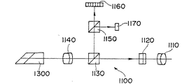
次に図2に基づいて、求心望遠鏡1100の光学的構成を説明する。
【0044】
求心望遠鏡1100は、接眼レンズ1110と、レクチル1120と、第1のビームスプリッタ1130と、対物レンズ1140と、第2のビームスプリッタ1150と、第1のCCD1160と、第2のCCD1170とを備えている。
【0045】
対物レンズ1140は、反射プリズム1300を介して、測標2000の機械高さ測定ターゲット2100の像(以下、ターゲット像と称する)を形成するためのものである。即ち対物レンズ1140は、十字線を備えたレクチル1120上にターゲット像を形成するものである。なお、対物レンズ1140とレクチル1120とは、光学手段に該当するものである。
【0046】
測量者は、接眼レンズ1110により、レクチル1120上に形成されたターゲット像を視準することができる。
【0047】
対物レンズ1140とレクチル1120との間には、第1のビームスプリッタ1130が挿入されており、第1のビームスプリッタ1130は、視準光を透過させてレクチル1120に向かわせると共に、一部の光を直角上方に反射させて測定光を形成させる様になっている。第1のビームスプリッタ1130で反射された測定光は、上方に配置された第2のビームスプリッタ1150により、第1測定光と第2測定光とに分離される。
【0048】
即ち、第1のビームスプリッタ1130からの測定光は、第2のビームスプリッタ1150を透過されたものが第1測定光となり、第2のビームスプリッタ1150で反射されて90度偏向されたものが、第2測定光となる。
【0049】
第1測定光は、第1の受光手段である第1のCCD1160に入射され、第2測定光は、第2の受光手段である第2のCCD1170に入射される様に構成されている。
【0050】
なお、第1のCCD1160と第2のCCD1170とは、レクチル1120と共役の位置にある。
【0051】
次に、機械高さHの測定の原理を説明する。
【0052】
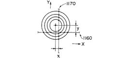
本実施例の機械高さ測定ターゲット2100は、図1に示す様に同心円状に形成されている。図3は、レクチル1120上に現れたターゲット像である。
【0053】
ここで、第1のCCD1160と第2のCCD1170とは、直交して受光する様に配置されているので、第1のCCD1160は、図3のX軸方向の位置を計測することができ、第2のCCD1170は、図3のY軸方向の位置を計測することができる。即ち図3は、レクチル1120上に現れたターゲット像と、第1のCCD1160と第2のCCD1170の位置とを、重ね合わせた状態を示すものである。
【0054】
そして、機械高さ測定ターゲット2100の中心である基準点からのX方向のズレ量をxとし、Y方向のズレ量をyとすれば、ズレ量xは、各円像(ターゲット像の同心円の内、それぞれの各円像)のX軸とのクロス点の内、1つだけ違った間隔をもつクロス点の中点の位置と、予め決められているX軸の0点との距離を演算すればよいことになる。なお、この演算は適宜の演算処理手段により実行される。
【0055】
同様にして、ズレ量yは、各円像(ターゲット像の同心円の内、それぞれの各円像)のY軸とのクロス点の内、1つだけ違った間隔をもつクロス点の中点の位置と、予め決められているY軸の0点との距離を演算すればよいことになる。更に、ズレ量x又はズレ量y、及びクロス点の1/2距離を3平方の定理に適用すれば、ターゲットの、特定の円像の半径を算出することができる。
【0056】
また、X軸又はY軸とクロスする交点の数及び、交点の間隔を検出することにより、各円像の円周は既知であることから、第1のCCD1160又は第2のCCD1170を横切る円周の直径を算出することができる。
【0057】
更に、2つのゼロクロス点の距離の1/2(1/2距離)も容易に計測できるので、特定の円像の半径と、(1/2距離)とを、3平方の定理に適用すれば、ズレ量x、及びズレ量yとを算出することができる。
【0058】
そしてターゲットの各円像の円周の直径は既知であるから、機械高さ測定ターゲット2100までの距離である機械高さHは、ターゲット像の光学的な倍率を用いて換算すれば、簡便に求めることができる。
【0059】
なお本実施例では、第1の受光手段と第2の受光手段の2つの受光手段を採用しているが、1方向測定後、測量機本体1000又は受光素子を90度回転させることにより、1つの受光手段でも実現可能である。
【0060】
以上の様に計測したズレ量x、及びズレ量y、そして機械高さHは、測量機本体1000に設けられた適宜の表示部1400に表示することができる。
【0061】
本実施例の機械高さ測定ターゲット2100は、同心円状に形成されているが、同心円状に限定されるものではなく、図4に示す様に、矩形にすることもできる。また図4は、第1の受光手段と第2の受光手段とが、矩形の中心線と直交する様に構成されているが、回転している場合にも同様に適用することができる。
【0062】
即ち、第1の受光手段と第2の受光手段の交点から、abとcdの長さを比較することにより、X方向のズレ量を算出することができる。また、第1の受光手段と第2の受光手段の交点の位置からY方向のズレ量を算出することができる。
【0063】
更に、回転し傾いている場合には、第1の受光手段と第2の受光手段の交点の位置から、回転量を算出し、そしてズレ量を演算することができる。また、測量機本体1000を回転してズレを補正してもよい。
【0064】
そして機械高さHは、ターゲットの矩形の大きさが既知であるので、第1の受光手段と第2の受光手段の受光位置からの比率により、機械高さ測定ターゲット2100までの距離である機械高さHを算出することができる。
【0065】
同様に、図5の様な機械高さ測定ターゲット2100を採用することもできる。
【0066】
図6は、受光手段が1つの場合であり、W状のターゲット像を横切る様に受光手段が配置されている。回転している場合には、交点ab、交点bc、交点cdの間隔は、それぞれ異なることになる。従って、X方向のズレ量は、交点ab、交点bcの間隔から算出することができ、Y方向のズレ量は、受光位置から同様に算出することができる。
【0067】
なお、現在最も多く使用される測量機であるトータルステーションは、電気的に水平角、高度角を測定すると共に、光波距離計を内蔵して距離の測定も可能となっている。この様なトータルステーションは、高速な演算手段が既に内蔵されており、求心位置のズレ量及び機械高さHを取り込み、測定値を瞬時に補正可能となっている。
【0068】
この様に構成されたトータルステーションは、本体を基準点上に概略設置すれば、自動的に、求心位置のズレ量及び機械高さHを取り込んで、補正された真の測定値を表示することができる。この様なトータルステーションは、角度検出手段には、光透過式エンコーダが用いられ、受光手段の受光信号を処理するための演算手段が内蔵されている。このため、ターゲット像の受光手段の受光信号を処理するための演算手段を追加する必要はない。
【0069】
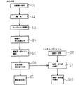
ここで、具体的な使用方法を図7に基づいて説明する。
【0070】
まず、ステップ1(以下、S1と略する)で、測量機本体1000を据え付ける。次に、S2に進み、整準作業を完了させる。
【0071】
そしてS3では、基準点に機械高さ測定ターゲット2100を設置する。次にS4では、測量者が、測量機本体1000の概略の求心位置合わせを行う。更にS5では、上述の方法により、ズレ量x、及びズレ量y、そして機械高さHを測定する。
【0072】
S5で測定された測定値は、S6で、測量機本体1000の記憶手段に記憶させる。そしてS7では、S6で記憶された測定値を、測量機本体1000の適宜の表示部1400に表示する。
【0073】
更に、測量機本体1000がトータルステーションの場合は、S8で、測距、測角作業を実施し、S9では、S6で記憶された測定値(ズレ量x、ズレ量y、機械高さH)を利用して、S8で求めた距離、角度の補正値を演算する。そしてS10では、S9で求めた補正値を図8で示すトータルステーションの適宜の表示部1400に表示する。
【0074】
なお、S8の測距は、適宜の光波距離計を使用することができ、S8の測角は、例えば図8の高度角エンコーダ1510により高度角を測定し、水平角エンコーダ1520により水平角を測定する構成にすることもできる。
【0075】
また、求心位置をレーザー光で示すレーザー求心装置と組み合わせれば、概略の位置合わせを行えばよく、更に、作業能率が向上するという効果がある。
【0076】
【効果】
以上の様に構成された本発明は、測量地点を特定するため、この測量地点に設置されたターゲットの像を形成するための光学手段と、このターゲット像を受光するための受光手段と、この受光手段からのターゲット像の受光信号に基づき、前記ターゲットまでの距離である機械高さを演算するための演算処理手段とからなり、前記ターゲットが同心円状に形成され、前記受光手段が、同心円状のターゲットによる各円像のX軸又はY軸との交点を検出する受光信号を形成し、前記演算処理手段が、前記交点の位置から、前記各円像の直径を算出し、この直径の値から対応する機械高さを演算する様に構成されているので、熟練者でなくとも、高い精度で測量作業を行うことができるという卓越した効果がある。
【0077】
そして本発明は、測量地点を特定するため、この測量地点に設置されたターゲットの像を形成するための光学手段と、このターゲット像を受光するための受光手段と、この受光手段からのターゲット像の受光信号に基づき、前記測量地点からのズレ量を演算するための演算処理手段とからなり、前記ターゲットが、同心円状に形成され、前記受光手段が、同心円状のターゲットによる各円像のX軸又はY軸との交点を検出する受光信号を形成し、前記演算処理手段が、前記交点の位置から、X軸方向のズレ量又はY軸方向のズレ量を演算する様に構成されているので、作業能率が向上するのみならず、正確な測量を実現することができるという卓越した効果がある。
【図面の簡単な説明】
【図1】本発明の実施例である測量機本体1000と測標2000とを説明する図である。
【図2】求心望遠鏡1100の光学的構成を説明する図である。
【図3】本実施例の原理を説明する図である。
【図4】本実施例の原理を説明する図である。
【図5】本実施例の原理を説明する図である。
【図6】本実施例の原理を説明する図である。
【図7】本実施例の作用を説明する図である。
【図8】トータルステーションの表示部1400を説明する図である。
【図9】従来技術を説明する図である。
【図10】従来技術を説明する図である。
【符号の説明】
1000 測量機本体
1100 求心望遠鏡
1110 接眼レンズ
1120 レクチル
1130 第1のビームスプリッタ
1140 対物レンズ
1150 第2のビームスプリッタ
1160 第1のCCD
1170 第2のCCD
1200 穴部
1300 反射プリズム
1400 表示部
1510 高度角エンコーダ
1520 水平角エンコーダ
2000 測標
2100 機械高さ測定ターゲット
3000 三脚
3100 整準台
3110 固定ネジ[0001]
[Industrial application fields]
The present invention relates to a centripetal position measuring apparatus for a surveying instrument, and more particularly to a centripetal position measuring apparatus for a surveying instrument capable of calculating a deviation amount x, a deviation amount y, and a machine height H with respect to a reference point. It is.
[0002]
[Prior art]
In general, the surveying work is performed based on a known reference point. A surveying instrument is installed on a reference point or a given point, and surveying work is performed based on this reference point or the like. For example, the theodolite performs surveying by measuring the collimation direction of a collimating telescope that is pivotably mounted about a vertical axis and a horizontal axis. In addition, the leveling instrument can measure the height difference of the collimation position.
[0003]
Since these surveying instruments are attached to a tripod and used, it is necessary to measure the height from the ground to the collimating telescope and the machine height required for height calculation.
[0004]
FIG. 9 shows a
[0005]
Further, as shown in FIG. 10, a
[0006]
The surveyor installs the
[0007]
[Problems to be solved by the invention]
However, the mechanical height H of the
[0008]
Usually, the base point to the
[0009]
Further, for accurate surveying and measurement of the machine height H, the
[0010]
That is, the
[0011]
This work requires extremely high skill, and if the work is not performed with great care, there is a problem that the leveling of the surveying
[0012]
In recent years, the measurement accuracy of the main body of the
[0013]
Therefore, the emergence of means capable of measuring the machine height H with high accuracy even if not an expert is strongly desired.
[0014]
[Means for Solving the Problems]
The present invention has been devised in view of the above problems, and in order to identify a surveying point, an optical unit for forming an image of a target installed at the surveying point, and a light receiving unit for receiving the target image. And an arithmetic processing means for calculating a mechanical height, which is a distance to the target, based on a light reception signal of the target image from the light receiving means, the target is formed concentrically, and the light receiving means A light receiving signal for detecting an intersection of each circular image with the X axis or the Y axis by a concentric target, and the arithmetic processing means calculates the diameter of each circular image from the position of the intersection, The corresponding machine height is calculated from the diameter value.
[0015]
In the present invention, in order to specify a surveying point, an optical unit for forming an image of a target installed at the surveying point, a light receiving unit for receiving the target image, and a target image from the light receiving unit Based on the received light signal, and an arithmetic processing means for calculating the amount of deviation from the surveying point, the target is formed in a concentric circle shape, and the light receiving means is an X of each circular image by the concentric circular target. A light reception signal for detecting an intersection with the axis or the Y axis is formed, and the arithmetic processing means calculates an amount of deviation in the X axis direction or an amount of deviation in the Y axis direction from the position of the intersection.
[0016]
The light receiving means of the present invention can also be constituted by a first light receiving means and a second light receiving means arranged so as to be able to receive light orthogonal to the first light receiving means.
[0017]
And this invention can also be set as the structure which correct | amends a measured value to the value from the measuring point which put the target.
[0024]
DETAILED DESCRIPTION OF THE INVENTION
In the present invention configured as described above, since the optical means identifies the surveying point, an image of the target installed at the surveying point is formed, and the light receiving means receives the target image, and the light receiving means Based on the received light signal of the target image, the arithmetic processing means calculates the machine height, which is the distance to the target, the target is formed concentrically, and the light receiving means is formed by each concentric target. A light reception signal for detecting the intersection of the circle image with the X axis or the Y axis is formed, and the arithmetic processing means calculates the diameter of each circle image from the position of the intersection, and calculates the corresponding machine height from the value of the diameter. It is configured to calculate.
[0025]
In the present invention, in order for the optical means to specify the survey point, an image of the target installed at the survey point is formed, and the light receiving means receives the target image, and the light reception signal of the target image from the light receiving means. The calculation processing means calculates the amount of deviation from the survey point, the target is formed concentrically, and the light receiving means is connected to the X axis or Y axis of each circular image by the concentric target. The light receiving signal for detecting the intersection is formed, and the arithmetic processing means calculates the amount of deviation in the X-axis direction or the amount of deviation in the Y-axis direction from the position of the intersection.
[0026]
The light receiving means of the present invention can be arranged such that the second light receiving means can receive light perpendicular to the first light receiving means.
[0027]
And this invention can also correct | amend a measured value to the value from the measuring point which put the target.
[0034]
【Example】
[0035]
Embodiments of the present invention will be described with reference to the drawings.
[0036]
FIG. 1 is a diagram for explaining a surveying instrument
[0037]
The state shown in FIG. 1 is a state before the leveling operation of the surveying instrument
[0038]
The machine
[0039]
A
[0040]
The leveling table 3100 is formed with a fixing
[0041]
The collimated light from the machine
[0042]
The collimation light that has passed through the
[0043]
Next, the optical configuration of the
[0044]
The
[0045]
The
[0046]
The surveyor can collimate the target image formed on the
[0047]
A
[0048]
That is, the measurement light from the
[0049]
The first measurement light is made incident on the
[0050]
Note that the
[0051]
Next, the principle of measuring the machine height H will be described.
[0052]
The machine
[0053]
Here, since the
[0054]
Then, if the amount of deviation in the X direction from the reference point which is the center of the machine
[0055]
Similarly, the amount of deviation y is the midpoint of the cross points having a different interval among the cross points with the Y axis of each circular image (the concentric circles of the target image). It is only necessary to calculate the distance between the position and a predetermined zero point on the Y axis. Furthermore, the radius of a specific circular image of the target can be calculated by applying the deviation amount x or the deviation amount y and the half distance of the cross point to the 3-square theorem.
[0056]
Further, since the circumference of each circular image is known by detecting the number of intersections crossing the X axis or the Y axis and the interval between the intersections, the circumference crossing the
[0057]
Furthermore, 1/2 (1/2 distance) of the distance between the two zero-cross points can be easily measured. Therefore, if the radius of a specific circular image and (1/2 distance) are applied to the 3-square theorem, , Displacement amount x, and displacement amount y can be calculated.
[0058]
Since the diameter of the circumference of each circular image of the target is known, the mechanical height H, which is the distance to the mechanical
[0059]
In this embodiment, two light receiving means, ie, a first light receiving means and a second light receiving means are employed. However, after measuring in one direction, the surveying instrument
[0060]
The displacement amount x, the displacement amount y, and the machine height H measured as described above can be displayed on an
[0061]
The machine
[0062]
That is, the amount of deviation in the X direction can be calculated by comparing the lengths of ab and cd from the intersection of the first light receiving means and the second light receiving means. Further, the amount of deviation in the Y direction can be calculated from the position of the intersection of the first light receiving means and the second light receiving means.
[0063]
Further, when the device is rotated and inclined, the amount of rotation can be calculated from the position of the intersection of the first light receiving means and the second light receiving means, and the amount of deviation can be calculated. Further, the surveying instrument
[0064]
The machine height H is the distance to the machine
[0065]
Similarly, a machine
[0066]
FIG. 6 shows a case where there is one light receiving means, and the light receiving means is arranged so as to cross the W-shaped target image. In the case of rotation, the intervals of the intersection ab, the intersection bc, and the intersection cd are different from each other. Accordingly, the amount of deviation in the X direction can be calculated from the interval between the intersection points ab and bc, and the amount of deviation in the Y direction can be similarly calculated from the light receiving position.
[0067]
The total station, which is currently the most frequently used surveying instrument, can measure the horizontal angle and altitude angle electrically, and can also measure the distance by incorporating a light wave distance meter. Such a total station already has a high-speed calculation means built in, and can take in the deviation of the centripetal position and the machine height H to instantaneously correct the measured value.
[0068]
The total station configured in this way can automatically display the corrected true measurement value by automatically taking in the displacement of the centripetal position and the machine height H if the main body is roughly installed on the reference point. it can. In such a total station, a light transmission type encoder is used as the angle detection means, and a calculation means for processing a light reception signal of the light reception means is incorporated. For this reason, it is not necessary to add a calculation means for processing the light reception signal of the light receiving means for the target image.
[0069]
Here, a specific method of use will be described with reference to FIG.
[0070]
First, in step 1 (hereinafter abbreviated as S1), the surveying instrument
[0071]
In S3, the machine
[0072]
The measured value measured in S5 is stored in the storage means of the surveying instrument
[0073]
Further, when the surveying instrument
[0074]
For the distance measurement in S8, an appropriate optical distance meter can be used. For the angle measurement in S8, for example, the altitude angle is measured by the
[0075]
In addition, when combined with a laser centripetal device that indicates the centripetal position with laser light, it is only necessary to perform approximate alignment, and the working efficiency is further improved.
[0076]
【effect】
In the present invention configured as described above, in order to specify a surveying point, an optical unit for forming an image of a target installed at the surveying point, a light receiving unit for receiving the target image, Comprising arithmetic processing means for calculating the mechanical height, which is the distance to the target, based on the light reception signal of the target image from the light receiving means, the target is formed concentrically, and the light receiving means is concentric A light reception signal for detecting the intersection of each circle image with the X axis or the Y axis by the target of the object, and the arithmetic processing means calculates the diameter of each circle image from the position of the intersection, and the value of the diameter Therefore, even if you are not an expert, you can perform surveying work with high accuracy.
[0077]
In the present invention, in order to specify a surveying point, an optical unit for forming an image of a target installed at the surveying point, a light receiving unit for receiving the target image, and a target image from the light receiving unit Based on the received light signal, and an arithmetic processing means for calculating the amount of deviation from the surveying point, the target is formed in a concentric circle shape, and the light receiving means is an X of each circular image by the concentric circular target. A light receiving signal for detecting an intersection with the axis or the Y axis is formed, and the arithmetic processing means is configured to calculate a deviation amount in the X axis direction or a deviation amount in the Y axis direction from the position of the intersection point. Therefore, not only the work efficiency is improved, but also an excellent effect that an accurate surveying can be realized.
[Brief description of the drawings]
FIG. 1 is a diagram for explaining a surveying instrument
FIG. 2 is a diagram illustrating an optical configuration of a
FIG. 3 is a diagram illustrating the principle of the present embodiment.
FIG. 4 is a diagram illustrating the principle of this embodiment.
FIG. 5 is a diagram illustrating the principle of the present embodiment.
FIG. 6 is a diagram illustrating the principle of the present embodiment.
FIG. 7 is a diagram for explaining the operation of this embodiment.
FIG. 8 is a diagram for explaining a
FIG. 9 is a diagram illustrating a conventional technique.
FIG. 10 is a diagram illustrating a conventional technique.
[Explanation of symbols]
1000 surveying instrument
1170 Second CCD
1200
Claims (4)
Priority Applications (4)
| Application Number | Priority Date | Filing Date | Title |
|---|---|---|---|
| JP20868998A JP3965593B2 (en) | 1998-07-08 | 1998-07-08 | Surveying device centripetal position measuring device and surveying instrument |
| EP99113565A EP0971207B1 (en) | 1998-07-08 | 1999-07-07 | Surveying instrument having a plumbing device |
| DE69934940T DE69934940T2 (en) | 1998-07-08 | 1999-07-07 | Surveying instrument with lot |
| US09/348,211 US6453569B1 (en) | 1998-07-08 | 1999-07-08 | Surveying instrument and plumbing device for plumbing surveying instrument |
Applications Claiming Priority (1)
| Application Number | Priority Date | Filing Date | Title |
|---|---|---|---|
| JP20868998A JP3965593B2 (en) | 1998-07-08 | 1998-07-08 | Surveying device centripetal position measuring device and surveying instrument |
Publications (2)
| Publication Number | Publication Date |
|---|---|
| JP2000028362A JP2000028362A (en) | 2000-01-28 |
| JP3965593B2 true JP3965593B2 (en) | 2007-08-29 |
Family
ID=16560452
Family Applications (1)
| Application Number | Title | Priority Date | Filing Date |
|---|---|---|---|
| JP20868998A Expired - Fee Related JP3965593B2 (en) | 1998-07-08 | 1998-07-08 | Surveying device centripetal position measuring device and surveying instrument |
Country Status (4)
| Country | Link |
|---|---|
| US (1) | US6453569B1 (en) |
| EP (1) | EP0971207B1 (en) |
| JP (1) | JP3965593B2 (en) |
| DE (1) | DE69934940T2 (en) |
Families Citing this family (27)
| Publication number | Priority date | Publication date | Assignee | Title |
|---|---|---|---|---|
| CA2292249C (en) * | 1999-11-19 | 2007-05-22 | Darrell G. B. Cline | Hydrant monument |
| JP4317639B2 (en) * | 2000-03-29 | 2009-08-19 | 株式会社トプコン | Laser surveyor |
| JP4588240B2 (en) * | 2001-04-04 | 2010-11-24 | 株式会社トプコン | Centripetal guidance device |
| JP3840119B2 (en) * | 2002-02-08 | 2006-11-01 | 株式会社ソキア | Laser centripetal device |
| JP4424665B2 (en) | 2004-07-30 | 2010-03-03 | 株式会社 ソキア・トプコン | Surveying instrument |
| WO2007090309A1 (en) * | 2006-02-08 | 2007-08-16 | Leica Geosystems Ag | Angle measuring device |
| WO2008077432A1 (en) * | 2006-12-27 | 2008-07-03 | Trimble Ab | Geodetic instrument and related method |
| US7748126B2 (en) * | 2007-10-17 | 2010-07-06 | Jianhong Lu | Laser straight liner |
| US8625086B2 (en) | 2008-02-12 | 2014-01-07 | Trimble Ab | Determining coordinates of a target in relation to a survey instrument having a camera |
| US8629905B2 (en) | 2008-02-12 | 2014-01-14 | Trimble Ab | Localization of a surveying instrument in relation to a ground mark |
| CN101970985B (en) | 2008-02-29 | 2013-06-12 | 特林布尔公司 | Determining coordinates of a target in relation to a survey instrument having at least two cameras |
| US8897482B2 (en) | 2008-02-29 | 2014-11-25 | Trimble Ab | Stereo photogrammetry from a single station using a surveying instrument with an eccentric camera |
| CN102128636A (en) * | 2010-12-22 | 2011-07-20 | 王四明 | Method for correcting eccentricity of vertical circle |
| DE102011002696A1 (en) * | 2011-01-14 | 2012-07-19 | Homag Holzbearbeitungssysteme Gmbh | processing device |
| US8539685B2 (en) | 2011-01-20 | 2013-09-24 | Trimble Navigation Limited | Integrated surveying and leveling |
| CN105300345B (en) * | 2015-11-10 | 2017-09-12 | 中国科学院长春光学精密机械与物理研究所 | Electro-optic theodolite multi-object tracking method |
| CN105973191B (en) * | 2016-06-16 | 2018-05-29 | 中国科学院西安光学精密机械研究所 | A kind of multi-load general-purpose type tracking platform |
| EP3264034B1 (en) | 2016-06-30 | 2020-02-26 | Leica Geosystems AG | Measuring device with height measurement system and method for measuring a height |
| CN106403916B (en) * | 2016-12-02 | 2018-10-02 | 淮阴工学院 | The total powerstation and its working method of alignment are measured based on digital image |
| CN107727119B (en) * | 2017-12-08 | 2023-09-29 | 江西省测绘成果质量监督检验测试中心 | Total powerstation ranging triaxial overlap ratio indoor type detection and adjustment device |
| JP6996961B2 (en) * | 2017-12-19 | 2022-01-17 | 株式会社トプコン | Surveying device |
| CN108507531B (en) * | 2018-04-18 | 2019-12-20 | 湖南科技大学 | Total station instrument high laser measurement system and use method |
| EP3660451B1 (en) | 2018-11-28 | 2022-04-27 | Hexagon Technology Center GmbH | Intelligent stationing module |
| CN109974673B (en) * | 2019-03-11 | 2024-03-15 | 中国人民解放军63883部队 | Multifunctional quick fine aiming point-to-point device |
| RU2730370C1 (en) * | 2019-10-21 | 2020-08-21 | Федеральное государственное унитарное предприятие "Научно-производственный центр автоматики и приборостроения имени академика Н.А. Пилюгина" (ФГУП "НПЦАП") | Automated device for attachment to reverse plumb lines |
| JP7438881B2 (en) * | 2020-07-29 | 2024-02-27 | 株式会社トプコン | Leveling platform, surveying equipment and surveying system |
| CN112483825B (en) * | 2020-11-12 | 2021-10-29 | 武汉理工大学 | Theodolite capable of automatically calibrating and leveling |
Family Cites Families (14)
| Publication number | Priority date | Publication date | Assignee | Title |
|---|---|---|---|---|
| US4171907A (en) * | 1978-05-25 | 1979-10-23 | Cubic Western Data | Electro-optic distance measuring device |
| JPS6065870A (en) * | 1983-09-19 | 1985-04-15 | 大成建設株式会社 | Pillar verticality detecting apparatus |
| CH672024A5 (en) * | 1987-03-02 | 1989-10-13 | Wild Leitz Ag Optik Feinmechan | |
| SE500856C2 (en) * | 1989-04-06 | 1994-09-19 | Geotronics Ab | Arrangements for use in surveying and / or launching work |
| DE4007245C2 (en) * | 1990-03-08 | 1999-10-14 | Leica Geosystems Ag | Device for centering a geodetic instrument over a defined point on the ground |
| US5218770A (en) * | 1990-11-27 | 1993-06-15 | Asahi Seimitsu Kabushiki Kaisha | Surveying machine for construction work |
| JP3226970B2 (en) * | 1992-07-09 | 2001-11-12 | 株式会社トプコン | Laser surveying machine |
| US5392521A (en) * | 1993-06-10 | 1995-02-28 | Allen; Michael P. | Surveyor's prism target |
| JP3681198B2 (en) * | 1995-05-25 | 2005-08-10 | 株式会社トプコン | Laser surveyor |
| JP3670075B2 (en) * | 1996-03-06 | 2005-07-13 | 株式会社トプコン | Appropriate height display device |
| JPH09257481A (en) * | 1996-03-26 | 1997-10-03 | Nikon Corp | Surveying instrument with attachment for measuring instrument height |
| US5949548A (en) * | 1997-01-22 | 1999-09-07 | Asahi Kogaku Kogyo Kabushiki Kaisha | Height sensing measurement device |
| JP3731021B2 (en) * | 1997-01-31 | 2006-01-05 | 株式会社トプコン | Position detection surveying instrument |
| DE19716304C1 (en) * | 1997-04-18 | 1998-05-20 | Zeiss Carl Jena Gmbh | Geodetic device for plumbline, theodolite or tachymeter |
-
1998
- 1998-07-08 JP JP20868998A patent/JP3965593B2/en not_active Expired - Fee Related
-
1999
- 1999-07-07 EP EP99113565A patent/EP0971207B1/en not_active Expired - Lifetime
- 1999-07-07 DE DE69934940T patent/DE69934940T2/en not_active Expired - Lifetime
- 1999-07-08 US US09/348,211 patent/US6453569B1/en not_active Expired - Lifetime
Also Published As
| Publication number | Publication date |
|---|---|
| JP2000028362A (en) | 2000-01-28 |
| US6453569B1 (en) | 2002-09-24 |
| DE69934940D1 (en) | 2007-03-15 |
| EP0971207A1 (en) | 2000-01-12 |
| DE69934940T2 (en) | 2007-05-24 |
| EP0971207B1 (en) | 2007-01-24 |
Similar Documents
| Publication | Publication Date | Title |
|---|---|---|
| JP3965593B2 (en) | Surveying device centripetal position measuring device and surveying instrument | |
| JP3583786B2 (en) | Method for opposing an object and position measuring sensor therefor | |
| CN100580374C (en) | Laser measuring method and laser measuring system | |
| US7200945B2 (en) | Surveying instrument | |
| CN1071898C (en) | Measuring ball reflector | |
| US11566897B2 (en) | Surveying instrument and method of calibrating a survey instrument | |
| US6055046A (en) | System and method for aligning a laser transmitter | |
| GB2354321A (en) | Geodetic device with a laser arrangement | |
| RU2463561C1 (en) | Apparatus for determining horizontal and vertical angle measurement error of geodesic goniometers | |
| JPH09280859A (en) | Tilt sensor and surveying device using the sensor | |
| JP2945467B2 (en) | Machine height measuring device | |
| CN111707229B (en) | Right-angle prism pitch and azimuth angle measurement and adjustment method for positioning and orienting equipment | |
| US4738532A (en) | Method of calibrating an optical measuring system | |
| JPH10293029A (en) | Surveying machine with machine height measurement function | |
| JP3718312B2 (en) | Machine height measuring device | |
| EP3249352B1 (en) | Optical device, focal plate incorporated in optical device, and measuring method using optical device | |
| JPS6046410A (en) | Survey device | |
| JP3481324B2 (en) | Method of measuring mechanical height of surveying instrument and measuring instrument | |
| JPH01184411A (en) | Height and distance measuring meter | |
| RU1573985C (en) | Direction maintenance device | |
| JP2000074670A (en) | Measuring device for height of measuring instrument | |
| JP3092302B2 (en) | Lightwave ranging system | |
| SU1744453A1 (en) | Device for calibration of two-coordinate autocollimators | |
| JP3000450B2 (en) | Electronic measuring board | |
| SU849005A1 (en) | Device for measuring angle between sighting target directions |
Legal Events
| Date | Code | Title | Description |
|---|---|---|---|
| A621 | Written request for application examination |
Free format text: JAPANESE INTERMEDIATE CODE: A621 Effective date: 20050621 |
|
| A977 | Report on retrieval |
Free format text: JAPANESE INTERMEDIATE CODE: A971007 Effective date: 20070201 |
|
| A131 | Notification of reasons for refusal |
Free format text: JAPANESE INTERMEDIATE CODE: A131 Effective date: 20070213 |
|
| A521 | Written amendment |
Free format text: JAPANESE INTERMEDIATE CODE: A523 Effective date: 20070412 |
|
| A521 | Written amendment |
Free format text: JAPANESE INTERMEDIATE CODE: A523 Effective date: 20070413 |
|
| TRDD | Decision of grant or rejection written | ||
| A01 | Written decision to grant a patent or to grant a registration (utility model) |
Free format text: JAPANESE INTERMEDIATE CODE: A01 Effective date: 20070515 |
|
| A61 | First payment of annual fees (during grant procedure) |
Free format text: JAPANESE INTERMEDIATE CODE: A61 Effective date: 20070516 |
|
| R150 | Certificate of patent or registration of utility model |
Free format text: JAPANESE INTERMEDIATE CODE: R150 |
|
| FPAY | Renewal fee payment (event date is renewal date of database) |
Free format text: PAYMENT UNTIL: 20100608 Year of fee payment: 3 |
|
| FPAY | Renewal fee payment (event date is renewal date of database) |
Free format text: PAYMENT UNTIL: 20110608 Year of fee payment: 4 |
|
| FPAY | Renewal fee payment (event date is renewal date of database) |
Free format text: PAYMENT UNTIL: 20110608 Year of fee payment: 4 |
|
| FPAY | Renewal fee payment (event date is renewal date of database) |
Free format text: PAYMENT UNTIL: 20120608 Year of fee payment: 5 |
|
| FPAY | Renewal fee payment (event date is renewal date of database) |
Free format text: PAYMENT UNTIL: 20120608 Year of fee payment: 5 |
|
| FPAY | Renewal fee payment (event date is renewal date of database) |
Free format text: PAYMENT UNTIL: 20130608 Year of fee payment: 6 |
|
| R250 | Receipt of annual fees |
Free format text: JAPANESE INTERMEDIATE CODE: R250 |
|
| R250 | Receipt of annual fees |
Free format text: JAPANESE INTERMEDIATE CODE: R250 |
|
| R250 | Receipt of annual fees |
Free format text: JAPANESE INTERMEDIATE CODE: R250 |
|
| R250 | Receipt of annual fees |
Free format text: JAPANESE INTERMEDIATE CODE: R250 |
|
| R250 | Receipt of annual fees |
Free format text: JAPANESE INTERMEDIATE CODE: R250 |
|
| LAPS | Cancellation because of no payment of annual fees |