JP2013123710A - Water purifier - Google Patents
Water purifier Download PDFInfo
- Publication number
- JP2013123710A JP2013123710A JP2012273490A JP2012273490A JP2013123710A JP 2013123710 A JP2013123710 A JP 2013123710A JP 2012273490 A JP2012273490 A JP 2012273490A JP 2012273490 A JP2012273490 A JP 2012273490A JP 2013123710 A JP2013123710 A JP 2013123710A
- Authority
- JP
- Japan
- Prior art keywords
- water
- main body
- water purifier
- hot water
- purifier according
- Prior art date
- Legal status (The legal status is an assumption and is not a legal conclusion. Google has not performed a legal analysis and makes no representation as to the accuracy of the status listed.)
- Granted
Links
- XLYOFNOQVPJJNP-UHFFFAOYSA-N water Substances O XLYOFNOQVPJJNP-UHFFFAOYSA-N 0.000 title claims abstract description 259
- 238000010438 heat treatment Methods 0.000 claims abstract description 57
- 230000000694 effects Effects 0.000 abstract description 3
- 238000009434 installation Methods 0.000 abstract description 3
- 238000007599 discharging Methods 0.000 abstract 1
- 239000002351 wastewater Substances 0.000 abstract 1
- 230000008878 coupling Effects 0.000 description 4
- 238000010168 coupling process Methods 0.000 description 4
- 238000005859 coupling reaction Methods 0.000 description 4
- 239000008213 purified water Substances 0.000 description 3
- 238000010586 diagram Methods 0.000 description 2
- 230000014509 gene expression Effects 0.000 description 2
- 239000008236 heating water Substances 0.000 description 2
- 239000008399 tap water Substances 0.000 description 2
- 235000020679 tap water Nutrition 0.000 description 2
- 238000007792 addition Methods 0.000 description 1
- 230000001580 bacterial effect Effects 0.000 description 1
- 238000004891 communication Methods 0.000 description 1
- 238000001816 cooling Methods 0.000 description 1
- 238000001914 filtration Methods 0.000 description 1
- JEGUKCSWCFPDGT-UHFFFAOYSA-N h2o hydrate Chemical compound O.O JEGUKCSWCFPDGT-UHFFFAOYSA-N 0.000 description 1
- 239000012535 impurity Substances 0.000 description 1
- 238000000034 method Methods 0.000 description 1
- 238000012986 modification Methods 0.000 description 1
- 230000004048 modification Effects 0.000 description 1
- 239000000126 substance Substances 0.000 description 1
- 239000008400 supply water Substances 0.000 description 1
- 239000012780 transparent material Substances 0.000 description 1
Images


Landscapes
- Water Treatment By Sorption (AREA)
Abstract
Description
本発明は、浄水器に関し、より詳細には、温水モジュールで加熱された水又は蒸気を浄水器の本体内部で排水できる浄水器に関する。 The present invention relates to a water purifier, and more particularly to a water purifier capable of draining water or steam heated by a hot water module inside the main body of the water purifier.
一般的に、浄水器は、物理的又は化学的方法で水をろ過して、不純物を除去する装置であり、水道水を複数のフィルターにかけて浄水した後、冷温水を供給する。そのために、浄水器に供給される原水である水道水は、浄水装置を経て浄水された後、温水タンク及び冷水タンクに分割供給され、それぞれ加熱装置と冷却装置により、一定温度の冷温水に変換され、供給可能な状態となる。また、浄水器は、冷温水の他にも加熱又は冷却されない常温の浄水を貯蔵するタンクを別途に設け、常温の浄水を供給することもできる。 In general, a water purifier is a device that removes impurities by filtering water by a physical or chemical method. After purifying tap water through a plurality of filters, cold and hot water is supplied. For this purpose, tap water, which is the raw water supplied to the water purifier, is purified through a water purifier and then dividedly supplied to a hot water tank and a cold water tank, and converted into cold and hot water at a constant temperature by a heating device and a cooling device, respectively. Is ready to be supplied. The water purifier can also be provided with a separate tank for storing room temperature purified water that is not heated or cooled in addition to cold / hot water, and can supply room temperature purified water.
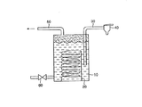
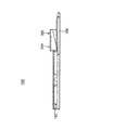
ここで、図1は、浄水器に内蔵された温水タンク10の構成を概略的に示した図である。図1を参照すると、浄水器の温水タンク10には、内部に収容された水を加熱するヒーター20が設けられる。ヒーター20により加熱された温水は、出水路30を通じて抽出され、抽出された温水は、浄水器の外側に設けられたコック40を介して使用者に供給することができる。
Here, FIG. 1 is a diagram schematically showing a configuration of a
また、温水タンク10の一側には、温水タンク10の内部への水供給を調節する弁60を設けることができる。
Further, a
一般的に、ヒーター20は、温水タンク10に収容された水を90℃以上に加熱するが、このとき、温水タンク10に収容された水が加熱されると、出水路30を通じて流出することがあるため、温水タンク10の上部には加熱管50が設けられる。これを通じて、温水タンク10で加熱された水又は蒸気は、加熱管50を通じてタンクの外部に排出することができる。
In general, the
一方、図2は、従来の浄水器1の加熱された水の排水構造を概略的に示したもので、従来の浄水器1は、図2に示されるように、浄水器1の内部の温水タンク10で加熱され加熱管50を通じて流出する水又は水蒸気を、シンク台や排水口などと連結されたドレン管、又は浄水器1の外部に別途に設けたタンクや水筒60に排水する構造を採用している。
On the other hand, FIG. 2 schematically shows the drainage structure of the heated water of the
このような場合、温水タンク10で加熱された温水が浄水器1の外部に流出されると、使用者の安全上に問題が発生する。
In such a case, if the hot water heated in the
また、シンク台や排水口などのような排水できる設備が近くにない区域に浄水器1を設置する場合、排水される水の水圧が弱いために、ドレン管を移動する水が、シンク台や排水口まで到逹できないという問題点がある。
In addition, when the
また、別途のタンクや水筒60を使用する場合には、外観が悪く、管理が容易でないという短所がある。
In addition, when a separate tank or
本発明は、上記した従来技術の問題点のうち少なくとも一部を解決するために案出されたもので、温水モジュールで加熱された水を浄水器の外部に排出できないような場所にも設置できる浄水器を提供することを目的とする。 The present invention has been devised to solve at least some of the problems of the prior art described above, and can be installed in a place where the water heated by the hot water module cannot be discharged outside the water purifier. The purpose is to provide a water purifier.
また、本発明は、簡単な構造で加熱された水を排水させ、排水された水の管理が容易な浄水器を提供することを目的とする。 It is another object of the present invention to provide a water purifier that drains heated water with a simple structure and is easy to manage the drained water.
上記目的を達成するために、本発明は、供給された水を加熱する温水モジュールが内部に設けられた本体と、上記温水モジュールに供給された水が加熱され、流出する水又は蒸気の移動経路を与える加熱管と、上記本体に取り付けられ、上記加熱管から流出する水又は蒸気を一時的に貯蔵する貯蔵手段とを含む浄水器を提供する。 In order to achieve the above object, the present invention provides a main body in which a hot water module for heating supplied water is provided, and a movement path of water or steam that flows out when the water supplied to the hot water module is heated. A water purifier is provided that includes a heating pipe for supplying water and a storage means attached to the main body and temporarily storing water or steam flowing out of the heating pipe.
一実施例における上記貯蔵手段は、上記加熱管から流出する水又は蒸気を貯蔵できる内部空間が形成された貯蔵部と、上記本体の内部に位置し、上記加熱管と連通し、上記加熱管から流出する水又は蒸気を上記貯蔵部に導くように上記貯蔵部に連通された流通部とを含んでいる。 In one embodiment, the storage means includes a storage portion in which an internal space capable of storing water or steam flowing out of the heating pipe is formed, and is located inside the main body, communicates with the heating pipe, and from the heating pipe. And a circulation part communicating with the storage part so as to guide the flowing water or steam to the storage part.
また、一実施例における上記流通部は、上記本体の内部に引出/引込自在に構成され、上記貯蔵部は、上記流通部を介して上記本体に取り付けられる。 Moreover, the said distribution part in one Example is comprised by the inside of the said main body so that drawing / drawing is possible, and the said storage part is attached to the said main body via the said distribution part.
上記流通部の底面は、上記貯蔵部側に下向きに傾き、上記流通部の側壁は、上記貯蔵部の側壁より高く形成されることが好ましい。 It is preferable that a bottom surface of the circulation part is inclined downward toward the storage part, and a side wall of the circulation part is formed higher than a side wall of the storage part.
一方、一実施例における浄水器は、上記本体の外側に設けられ、温水が抽出される取水部をさらに含み、上記貯蔵部は、上記本体の外側の上記取水部の下方に配置され、取水時にこぼれる水を一時的に貯蔵するトレイを含んでいる。 On the other hand, the water purifier in one embodiment further includes a water intake unit that is provided on the outside of the main body and from which hot water is extracted, and the storage unit is disposed below the water intake unit on the outside of the main body. Includes a tray to temporarily store spilled water.
ここで、上記流通部は、上記トレイの一側に突出して形成されてもよい。 Here, the distribution part may be formed to protrude to one side of the tray.
一方、上記温水モジュールは、供給された水を内部空間に貯蔵して、加熱する温水タンクを含んでもよく、瞬間加熱装置で構成されてもよい。 Meanwhile, the hot water module may include a hot water tank that stores and heats the supplied water in the internal space, and may be configured by an instantaneous heating device.
また、他の一実施例における上記貯蔵手段は、上記本体の内部に設けたタンク部材を含む。 In another embodiment, the storage means includes a tank member provided inside the main body.
上記タンク部材は、上記本体の一側で引出/引込自在に構成することができる。 The tank member can be configured to be drawn / retracted on one side of the main body.
また、上記タンク部材には、貯蔵された水の水位を上記本体の外部で確認できるように表示する水位表示部が設けられる。 Further, the tank member is provided with a water level display unit for displaying the stored water level so that the water level can be confirmed outside the main body.
このような構成を有する本発明によると、温水モジュールで加熱された水を本体の内部で排水できるため、排水される水を貯蔵する別途の装置を必要とせず、浄水器の設置が簡単で、加熱された水を処理する排水施設がない場所にも設置することができ、設置場所に制約がないという効果が得られる。 According to the present invention having such a configuration, the water heated by the hot water module can be drained inside the main body, so there is no need for a separate device for storing the drained water, and the installation of the water purifier is simple. It can be installed in a place where there is no drainage facility for treating heated water, and there is an effect that there is no restriction on the installation place.
また、本発明によると、浄水器のトレイに加熱された水が貯蔵されるため、浄水器の管理が容易であるという効果が得られる。 Moreover, according to this invention, since the heated water is stored by the tray of a water purifier, the effect that management of a water purifier is easy is acquired.
本明細書で使用する用語は、単に特定の実施例を説明するために使用したものであり、本発明を限定する意図ではない。また、本明細書における単数の表現は、文脈上明白に違う意味でない限り、複数の表現を含む。 The terminology used herein is for the purpose of describing particular embodiments only and is not intended to be limiting of the invention. In addition, the singular expression in this specification includes a plurality of expressions unless the context clearly indicates otherwise.
そして、本明細書における「含む」、「設ける」、「有する」などの用語は、明細書に記載された特徴、数字、段階、動作、構成要素、部品又はこれらの組み合わせがあることを指し示すものであって、一つ又はそれ以上の他の特徴、数字、段階、動作、構成要素、部品又はこれらの組み合わせ又は付加可能性を排除するものではないと理解すべきである。 In this specification, terms such as “including”, “providing”, “having” indicate that there are features, numbers, steps, operations, components, parts, or combinations thereof described in the specification. It should be understood that it does not exclude one or more other features, numbers, steps, operations, components, parts, or combinations or additions thereof.
以下、添付の図面を参考し、本発明の好ましい実施例について説明する。 Hereinafter, preferred embodiments of the present invention will be described with reference to the accompanying drawings.
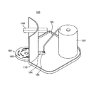
まず、図3〜図5を参照し、本発明の一実施例による浄水器について説明する。ここで、図3は本発明の一実施例による浄水器本体の上部が開放された概略的な斜視図であり、図4は平面図あり、図5は底面図である。 First, with reference to FIGS. 3-5, the water purifier by one Example of this invention is demonstrated. Here, FIG. 3 is a schematic perspective view in which an upper portion of a water purifier main body according to an embodiment of the present invention is opened, FIG. 4 is a plan view, and FIG. 5 is a bottom view.
図3〜図5に示すように、本発明の一実施例による浄水器100は、本体110と、取水部140と、加熱管150と、貯蔵手段160とを含む。
As shown in FIGS. 3 to 5, the
上記本体110の内部には、水を貯蔵し加熱する温水モジュール120が設けられている。
Inside the
図3〜図9に示された実施例における温水モジュール120は、供給された水を内部空間に貯蔵して加熱する温水タンクで構成することができる。ここで、温水モジュール120に採用される温水タンクには、原水圧により温水を排出する直水式温水タンクと、タンク圧により温水を排出するタンク式温水タンクに貯蔵した水を加熱する多様なタイプの温水タンクがある。
The
そして、図示しなかったが、他の実施例において、温水モジュール120は水を貯蔵せず、流れる水を加熱して温水にする瞬間加熱装置(図示略)で構成されてもよい。
And although not shown in figure, in another Example, the
一方、本発明の実施例による浄水器100における本体110は、後述する取水部140を設けた前面が湾曲した形態であるが、これは実施例に過ぎず、本体110は特定の形態に制限されない。
On the other hand, the
そして、温水モジュール120は内部に水を収容することができ、加熱手段(図示略)により収容された水を加熱することができる。このように温水モジュール120で加熱された水は、温水供給路130を通じて浄水器100の取水部140に流れ、使用者に供給される。但し、図3及び図4には、温水供給路130の具体的な連結構成を示さなかった。
And the
また、上記取水部140は、本体110の外側に設けられ、温水、冷水及び浄水を選択的に抽出できるように構成されている。取水部140は、一般的に浄水器100の前面に取り付けられる蛇口又はコック弁で構成することができる。
Moreover, the said
一実施例における取水部140は、図3に示すように異なる温度の水がそれぞれ流通できる複数の流路(図示略)に連結された一つの蛇口で構成してもよいが、これに限定されず、使用者に水を供給できる多様な構成を採用することができる。
The
また、上記加熱管150は、温水モジュール120に収容された水が加熱され、流出する水又は蒸気の移動経路を与えることができる。
In addition, the
即ち、温水モジュール120に収容された水が加熱されると、温水モジュール120の内部圧力により、微量の水や蒸気が温水供給路130に逆流することがあるが、これを防止するために、温水モジュール120の上部には加熱された水や蒸気が温水モジュール120の外部に流出するための加熱管150を設けることができる。
That is, when the water stored in the
そして、上述のように、本発明の他の実施例において、上記温水モジュール120が瞬間加熱装置で構成される場合、加熱管150は、瞬間加熱装置の本体又は瞬間加熱装置の出水管に連結されるので、瞬間加熱装置で加熱された蒸気が流通する流路を構成することができる。
As described above, in another embodiment of the present invention, when the
一方、上記貯蔵手段160は、本体110に取り付けられ、加熱管150から流出する水又は蒸気を一時的に貯蔵することができる。即ち、加熱管150は、本体110の内部で貯蔵手段160に連結され、水又は蒸気を排出できるように構成される。
Meanwhile, the
一実施例における貯蔵手段160は、貯蔵部162及び流通部164を含む構成とすることができる。
In one embodiment, the
ここで、上記貯蔵部162は、加熱管150から流出する水又は蒸気を貯蔵する内部空間を有する。
Here, the
また、上記流通部164は、本体110の内部に位置し、加熱管150に連通し、加熱管150から流出する水又は蒸気を貯蔵部162に導くように貯蔵部162に連通する。
The
一方、図3〜図7に示された本発明の一実施例における上記貯蔵部162は、本体110の外側の取水部140の下方に配置され、取水時にこぼれる水を一時的に貯蔵することができるトレイ(tray)で構成してもよい。
Meanwhile, the
以下では、このような一実施例により、貯蔵部162がトレイで構成された実施例を説明する。但し、本発明の一実施例による浄水器100は、貯蔵手段160の貯蔵部162がトレイで構成されることに限定されず、貯蔵手段160がトレイと区別される独立した部品で構成されてもよい。
Hereinafter, an embodiment in which the
一方、図3〜図7に示されたように、貯蔵手段160の貯蔵部162がトレイで構成された場合、上記流通部164はトレイの一側に突出して形成することができる。
Meanwhile, as illustrated in FIGS. 3 to 7, when the
また、貯蔵手段160は、本体110の前面で着脱自在に構成されてよい。そして、本発明の実施例による浄水器100において、貯蔵部162として構成されたトレイは外観が円形となっているが、この形状に限定されない。
In addition, the
また、上記流通部164は、本体110の内部で加熱管150と連通され、かつ、貯蔵部162と連通する。即ち、流通部164は、図3及び図4に示すように貯蔵部162の本体110との結合部側に設けてもよく、内部に水が流通する流路を形成している。また、流通部164の流路は、流通する水が貯蔵部162に移動できるように貯蔵部162に連通させてもよい。
The
一実施例において、本体110に貯蔵手段160が取り付けられると、貯蔵手段160の流通部164は、本体110の内部に引き込むことができる。また、流通部164の上部には、水が流通できる流入口165が形成されており、温水モジュール120に連結される加熱管150の末端は、流入口165の上部に位置する。
In one embodiment, when the
一実施例において、加熱管150の末端は、本体110の内部で位置が固定されていてもよく、貯蔵手段160が本体110に取り付けられるとき、流通部164は、加熱管150の末端の下部に位置するように構成され、加熱管150に連通する。ここで、連通とは、加熱管150から流通部164に水が流通することを意味する。
In one embodiment, the end of the
一方、図示しなかったが、他の一実施例において、本体110の内側には、流通部164が連結される結合ボックスを形成してもよい。また、結合ボックスの上部には、加熱管150を連結するノズルを設けることができる。このような構成では、貯蔵手段160が本体110に取り付けられるとき、流通部164は、結合ボックスに挿入され、ノズルを介して加熱管150と連通する。
On the other hand, although not shown, in another embodiment, a coupling box to which the
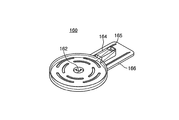
また、一実施例における流通部164は、本体110に強固に引込結合されてよく、貯蔵手段160は、流通部164を介して本体110に取り付けられる。そのために、流通部164の下端には、図5に示すように貯蔵部162の底部から延長される固定プレート部166が、流通部164の周囲に沿って形成される。このような固定プレート部166は、本体110の底面に形成されたガイドレール112に結合する。
In addition, the
このような構成を有する本発明の一実施例による浄水器100において、温水モジュール120に収容された水が加熱され、流出する水又は蒸気は、加熱管150に沿って移動することができ、蒸気は加熱管150で冷却されて水に変換される。ここで、加熱管150は、本体110に取り付けられた貯蔵手段160の方向に下向きに傾いて延長された構造で構成されている。
In the
このような加熱管150に沿って移動した水は、貯蔵手段160の流通部164に形成された流入口165を通じて流通部164に移動し、流通部164と連通された貯蔵部162に移動する。
The water moved along the
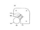
次に、図6及び図7を参照し、本発明の一実施例による浄水器に取り付けられる貯蔵手段160についてより詳しく説明する。ここで、図6は貯蔵手段160の斜視図であり、図7は側面図である。 Next, with reference to FIG.6 and FIG.7, the storage means 160 attached to the water purifier by one Example of this invention is demonstrated in detail. 6 is a perspective view of the storage means 160, and FIG. 7 is a side view.
図6及び図7に示すように、本発明の一実施例による浄水器100に取り付けられる貯蔵手段160において、流通部164に流入された水が貯蔵部162に円滑に流通するように、流通部164の底面は、貯蔵部162側に下向きに傾くように形成される。
As shown in FIGS. 6 and 7, in the storage means 160 attached to the
また、このように流通部164の底面が傾いて形成された構造により、加熱管150から貯蔵部162に流れる水が、本体110の内部に逆流するのを防止できる。
In addition, the structure in which the bottom surface of the
また、本発明の一実施例による浄水器100における貯蔵部162は、浄水器100の外側の取水部140の下方に配置されるため、使用者が水位を確認することができ、水が溢れる場合にも、浄水器100の本体110の外部に溢れるため、問題ない。水が流通部164で本体110の内部に溢れる場合は、浄水器100の内部に設けられた部品に水が流入して機械故障、細菌繁殖などの問題が発生することがある。
Moreover, since the
これを防止するため、一実施例において、流通部164の側壁は、貯蔵部162の側壁より高く形成することができる。この構成は、貯蔵部162の水が溢れる場合、流通部164の周囲、即ち、本体110の内部に水が溢れることを防止できる。
In order to prevent this, in one embodiment, the side wall of the
次に、図8及び図9を参照し、本発明の他の一実施例による浄水器について説明する。ここで、図8は本発明の他の一実施例による本体の上部が開放された斜視図であり、図9はタンク部材が分離された分解斜視図である。 Next, with reference to FIG.8 and FIG.9, the water purifier by other one Example of this invention is demonstrated. Here, FIG. 8 is a perspective view in which an upper portion of a main body according to another embodiment of the present invention is opened, and FIG. 9 is an exploded perspective view in which a tank member is separated.
図8及び図9に示すように、本発明の他の一実施例による浄水器100’における貯蔵手段は、本体110の内部に設けられるタンク部材170で構成することができる。
As shown in FIGS. 8 and 9, the storage means in the
ここで、本体110、温水モジュール120及び取水部140は、図3〜図5を参照して説明した内容と実質的に同一であり、取水部140の下部に、一般的に浄水器100に設けたトレイ180を配置することができる。
Here, the
上記タンク部材170は、本体110の内部で加熱管150に連結されて加熱管150から流出する水を貯蔵することができる。
The
他の一実施例において、温水モジュール120から出て加熱管150に移動する水が、タンク部材170に円滑に移動できるようにタンク部材170の高さは温水モジュール120より低く構成することができる。
In another embodiment, the height of the
また、タンク部材170は、図9に示されたように本体110の一側で引出/引込自在に構成することができる。使用者はタンク部材170に貯蔵された水を処理するためにタンク部材170を本体110から引き出すことができる。
Further, the
このような構成のため、他の一実施例において、加熱管150の末端は本体110の内部で一定位置に固定されてよく、タンク部材170が本体110に完全に引き込まれると、タンク部材170の上端に形成された流通口172は加熱管150の末端の下部に近接して配置することができる。
Due to such a configuration, in another embodiment, the end of the
これにより、加熱管150から流出する水は、流通口172を通じてタンク部材170の内部に貯蔵することができる。
Thereby, the water flowing out from the
また、他の一実施例におけるタンク部材170は、本体110に引き込まれる場合、本体110の一部を含むように構成されてよく、外側には容易に引出/引込ができるように取っ手174を設けることができる。
Further, the
一方、タンク部材170には、貯蔵された水の水位が本体110の外部で確認できるように表示する水位表示部176を設けてもよい。使用者は、水位表示部176によりタンク部材170に貯蔵された水の処理時期が分かる。
On the other hand, the
図9に示された実施例において、水位表示部176は、タンク部材170の内部に収容される水の水位を肉眼で識別できるように、タンク部材170を透明材質で構成してもよいが、これに限定されず、タンク部材170に収容された水の水位を検知し表示する電子式装置を設けてもよい。
In the embodiment shown in FIG. 9, the water
本発明は、特定の実施例に関して図示し説明したが、当業界において通常の知識を有する者であれば、添付の特許請求の範囲に記載された本発明の思想及び領域から外れない範囲内で本発明を多様に修正及び変更できることは自明である。 While the invention has been illustrated and described with reference to specific embodiments, those skilled in the art will recognize that the invention is within the spirit and scope of the invention as set forth in the appended claims. Obviously, various modifications and changes can be made to the present invention.
100、100’ 浄水器
110 本体
112 ガイドレール
120 温水モジュール
130 温水供給路
140 取水部
150 加熱管
160 貯蔵手段
162 貯蔵部
164 流通部
165 流入口
166 固定プレート部
170 タンク部材
172 流通口
174 取っ手
176 水位表示部
100, 100 '
Claims (12)
前記温水モジュールに供給された水が加熱され、流出する水又は蒸気の移動経路を与える加熱管と、
前記本体に取り付けられ、前記加熱管から流出する水又は蒸気を一時的に貯蔵する貯蔵手段と、を含む浄水器。 A main body provided with a hot water module for heating the supplied water;
A heating tube that heats the water supplied to the hot water module and provides a moving path for the flowing water or steam;
A water purifier, which is attached to the main body and includes storage means for temporarily storing water or steam flowing out from the heating pipe.
前記加熱管から流出する水又は蒸気を貯蔵できる内部空間が形成された貯蔵部と、
前記本体の内部に位置し、前記加熱管と連通し、前記加熱管から流出する水又は蒸気を前記貯蔵部に導くように前記貯蔵部に連通された流通部と、を含んでいることを特徴とする請求項1に記載の浄水器。 The storage means is
A storage part in which an internal space capable of storing water or steam flowing out of the heating pipe is formed;
A circulation part located inside the main body, communicating with the heating pipe, and communicating with the storage part so as to guide water or steam flowing out from the heating pipe to the storage part. The water purifier according to claim 1.
前記貯蔵部は、前記流通部を介して前記本体に取り付けられることを特徴とする請求項2に記載の浄水器。 The circulation part is configured to be freely drawn / drawn into the main body,
The water purifier according to claim 2, wherein the storage unit is attached to the main body through the circulation unit.
前記貯蔵部は、前記本体の外側の前記取水部の下方に配置され、取水時にこぼれる水を一時的に貯蔵するトレイを含むことを特徴とする請求項2〜5のいずれか1項に記載の浄水器。 A water intake unit provided outside the main body and from which hot water is extracted;
The said storage part is arrange | positioned under the said water intake part of the outer side of the said main body, and contains the tray which stores temporarily the water which spills at the time of water intake, The Claim 1 characterized by the above-mentioned. Water purifier.
Applications Claiming Priority (4)
| Application Number | Priority Date | Filing Date | Title |
|---|---|---|---|
| KR20110134737 | 2011-12-14 | ||
| KR10-2011-0134737 | 2011-12-14 | ||
| KR10-2012-0131228 | 2012-11-19 | ||
| KR1020120131228A KR101916888B1 (en) | 2011-12-14 | 2012-11-19 | Water purifier |
Publications (2)
| Publication Number | Publication Date |
|---|---|
| JP2013123710A true JP2013123710A (en) | 2013-06-24 |
| JP6279205B2 JP6279205B2 (en) | 2018-02-14 |
Family
ID=48775292
Family Applications (1)
| Application Number | Title | Priority Date | Filing Date |
|---|---|---|---|
| JP2012273490A Active JP6279205B2 (en) | 2011-12-14 | 2012-12-14 | Water purifier |
Country Status (1)
| Country | Link |
|---|---|
| JP (1) | JP6279205B2 (en) |
Cited By (1)
| Publication number | Priority date | Publication date | Assignee | Title |
|---|---|---|---|---|
| CN109896679A (en) * | 2017-12-07 | 2019-06-18 | 青岛经济技术开发区海尔热水器有限公司 | A kind of water purifier preheater and water purifier |
Citations (11)
| Publication number | Priority date | Publication date | Assignee | Title |
|---|---|---|---|---|
| US3568887A (en) * | 1967-11-13 | 1971-03-09 | Jet Spray Cooler Inc | Hot beverage dispenser |
| JPS5994240U (en) * | 1982-12-16 | 1984-06-26 | 東芝機器株式会社 | water heater |
| JPH1073316A (en) * | 1996-05-25 | 1998-03-17 | Samsung Electron Co Ltd | Cool and hot water cleaner |
| JP2002191506A (en) * | 2000-12-26 | 2002-07-09 | Toshiba Electric Appliance Co Ltd | Beverage providing device |
| JP2003262395A (en) * | 2002-03-11 | 2003-09-19 | Meisui:Kk | Cold/hot purified water supplying device |
| JP2007015706A (en) * | 2005-07-05 | 2007-01-25 | Japan Beverage Inc | Beverage dispenser |
| JP2008264486A (en) * | 2007-03-29 | 2008-11-06 | Fuji Electric Retail Systems Co Ltd | Beverage feeder |
| JP2009078090A (en) * | 2007-09-27 | 2009-04-16 | Sanyo Electric Co Ltd | Beverage dispenser |
| JP2010131549A (en) * | 2008-12-05 | 2010-06-17 | Panasonic Electric Works Co Ltd | Apparatus for producing electrolytic water |
| JP2010196943A (en) * | 2009-02-24 | 2010-09-09 | Teraoka Seiko Co Ltd | Water heater |
| JP3170185U (en) * | 2011-06-14 | 2011-09-08 | 祥行 西岡 | Water server |
-
2012
- 2012-12-14 JP JP2012273490A patent/JP6279205B2/en active Active
Patent Citations (11)
| Publication number | Priority date | Publication date | Assignee | Title |
|---|---|---|---|---|
| US3568887A (en) * | 1967-11-13 | 1971-03-09 | Jet Spray Cooler Inc | Hot beverage dispenser |
| JPS5994240U (en) * | 1982-12-16 | 1984-06-26 | 東芝機器株式会社 | water heater |
| JPH1073316A (en) * | 1996-05-25 | 1998-03-17 | Samsung Electron Co Ltd | Cool and hot water cleaner |
| JP2002191506A (en) * | 2000-12-26 | 2002-07-09 | Toshiba Electric Appliance Co Ltd | Beverage providing device |
| JP2003262395A (en) * | 2002-03-11 | 2003-09-19 | Meisui:Kk | Cold/hot purified water supplying device |
| JP2007015706A (en) * | 2005-07-05 | 2007-01-25 | Japan Beverage Inc | Beverage dispenser |
| JP2008264486A (en) * | 2007-03-29 | 2008-11-06 | Fuji Electric Retail Systems Co Ltd | Beverage feeder |
| JP2009078090A (en) * | 2007-09-27 | 2009-04-16 | Sanyo Electric Co Ltd | Beverage dispenser |
| JP2010131549A (en) * | 2008-12-05 | 2010-06-17 | Panasonic Electric Works Co Ltd | Apparatus for producing electrolytic water |
| JP2010196943A (en) * | 2009-02-24 | 2010-09-09 | Teraoka Seiko Co Ltd | Water heater |
| JP3170185U (en) * | 2011-06-14 | 2011-09-08 | 祥行 西岡 | Water server |
Cited By (1)
| Publication number | Priority date | Publication date | Assignee | Title |
|---|---|---|---|---|
| CN109896679A (en) * | 2017-12-07 | 2019-06-18 | 青岛经济技术开发区海尔热水器有限公司 | A kind of water purifier preheater and water purifier |
Also Published As
| Publication number | Publication date |
|---|---|
| JP6279205B2 (en) | 2018-02-14 |
Similar Documents
| Publication | Publication Date | Title |
|---|---|---|
| KR100900300B1 (en) | Water dispenser | |
| ES2604116T3 (en) | Device for providing liquid for a beverage vending machine and its use | |
| CN101970335B (en) | Water dispenser with reservoir system and the leading manifold for it | |
| WO2009057303A1 (en) | Hot water supply system | |
| KR101884736B1 (en) | Under sink type water dispenser | |
| KR20180045757A (en) | Under sink type water dispenser | |
| JP5529317B1 (en) | Water server | |
| CN105147118A (en) | Cold can assembly and compressor refrigerating water dispenser | |
| JP6504646B2 (en) | Storage tank internal structure | |
| JP6279205B2 (en) | Water purifier | |
| JP3166606U (en) | Undercounter type beverage dispenser | |
| JP2018122909A (en) | Beverage supply device | |
| KR100993891B1 (en) | Purifier | |
| JP2010002061A (en) | Storage type water heater | |
| KR200425269Y1 (en) | A vending machine for coffee using purifed water | |
| US20220127161A1 (en) | Liquid purifier | |
| KR101916888B1 (en) | Water purifier | |
| KR101772163B1 (en) | Bottled water dispenser with hot water stream rapid sterilization function | |
| JP2013148312A (en) | Storage type water heater | |
| KR102288480B1 (en) | Dispenser for beverage | |
| KR101772162B1 (en) | Water stream water purifier with a high temperature sterilization function | |
| TWI570368B (en) | Drinking water machine with quick heat exchange device with double barrel | |
| CN104367190B (en) | Energy-saving instant heat type drinking water platform | |
| JP7100749B1 (en) | Hot bath facility | |
| KR101763330B1 (en) | Air in pipe eliminating system of dispenser for hot and cool drink |
Legal Events
| Date | Code | Title | Description |
|---|---|---|---|
| A621 | Written request for application examination |
Free format text: JAPANESE INTERMEDIATE CODE: A621 Effective date: 20151023 |
|
| A977 | Report on retrieval |
Free format text: JAPANESE INTERMEDIATE CODE: A971007 Effective date: 20161026 |
|
| A131 | Notification of reasons for refusal |
Free format text: JAPANESE INTERMEDIATE CODE: A131 Effective date: 20161130 |
|
| A601 | Written request for extension of time |
Free format text: JAPANESE INTERMEDIATE CODE: A601 Effective date: 20170228 |
|
| A521 | Request for written amendment filed |
Free format text: JAPANESE INTERMEDIATE CODE: A523 Effective date: 20170303 |
|
| A131 | Notification of reasons for refusal |
Free format text: JAPANESE INTERMEDIATE CODE: A131 Effective date: 20170802 |
|
| A521 | Request for written amendment filed |
Free format text: JAPANESE INTERMEDIATE CODE: A523 Effective date: 20171101 |
|
| TRDD | Decision of grant or rejection written | ||
| A01 | Written decision to grant a patent or to grant a registration (utility model) |
Free format text: JAPANESE INTERMEDIATE CODE: A01 Effective date: 20180109 |
|
| A61 | First payment of annual fees (during grant procedure) |
Free format text: JAPANESE INTERMEDIATE CODE: A61 Effective date: 20180117 |
|
| R150 | Certificate of patent or registration of utility model |
Ref document number: 6279205 Country of ref document: JP Free format text: JAPANESE INTERMEDIATE CODE: R150 |
|
| R250 | Receipt of annual fees |
Free format text: JAPANESE INTERMEDIATE CODE: R250 |
|
| R250 | Receipt of annual fees |
Free format text: JAPANESE INTERMEDIATE CODE: R250 |
|
| R250 | Receipt of annual fees |
Free format text: JAPANESE INTERMEDIATE CODE: R250 |
|
| R250 | Receipt of annual fees |
Free format text: JAPANESE INTERMEDIATE CODE: R250 |