JP2006106272A - Display apparatus - Google Patents
Display apparatus Download PDFInfo
- Publication number
- JP2006106272A JP2006106272A JP2004291636A JP2004291636A JP2006106272A JP 2006106272 A JP2006106272 A JP 2006106272A JP 2004291636 A JP2004291636 A JP 2004291636A JP 2004291636 A JP2004291636 A JP 2004291636A JP 2006106272 A JP2006106272 A JP 2006106272A
- Authority
- JP
- Japan
- Prior art keywords
- housing
- heat sink
- heat
- display panel
- light source
- Prior art date
- Legal status (The legal status is an assumption and is not a legal conclusion. Google has not performed a legal analysis and makes no representation as to the accuracy of the status listed.)
- Pending
Links
Images


Classifications
-
- G—PHYSICS
- G06—COMPUTING; CALCULATING OR COUNTING
- G06F—ELECTRIC DIGITAL DATA PROCESSING
- G06F1/00—Details not covered by groups G06F3/00 - G06F13/00 and G06F21/00
- G06F1/16—Constructional details or arrangements
- G06F1/20—Cooling means
-
- G—PHYSICS
- G06—COMPUTING; CALCULATING OR COUNTING
- G06F—ELECTRIC DIGITAL DATA PROCESSING
- G06F1/00—Details not covered by groups G06F3/00 - G06F13/00 and G06F21/00
- G06F1/16—Constructional details or arrangements
- G06F1/1601—Constructional details related to the housing of computer displays, e.g. of CRT monitors, of flat displays
-
- H—ELECTRICITY
- H04—ELECTRIC COMMUNICATION TECHNIQUE
- H04N—PICTORIAL COMMUNICATION, e.g. TELEVISION
- H04N5/00—Details of television systems
- H04N5/64—Constructional details of receivers, e.g. cabinets or dust covers
-
- G—PHYSICS
- G02—OPTICS
- G02F—OPTICAL DEVICES OR ARRANGEMENTS FOR THE CONTROL OF LIGHT BY MODIFICATION OF THE OPTICAL PROPERTIES OF THE MEDIA OF THE ELEMENTS INVOLVED THEREIN; NON-LINEAR OPTICS; FREQUENCY-CHANGING OF LIGHT; OPTICAL LOGIC ELEMENTS; OPTICAL ANALOGUE/DIGITAL CONVERTERS
- G02F1/00—Devices or arrangements for the control of the intensity, colour, phase, polarisation or direction of light arriving from an independent light source, e.g. switching, gating or modulating; Non-linear optics
- G02F1/01—Devices or arrangements for the control of the intensity, colour, phase, polarisation or direction of light arriving from an independent light source, e.g. switching, gating or modulating; Non-linear optics for the control of the intensity, phase, polarisation or colour
- G02F1/13—Devices or arrangements for the control of the intensity, colour, phase, polarisation or direction of light arriving from an independent light source, e.g. switching, gating or modulating; Non-linear optics for the control of the intensity, phase, polarisation or colour based on liquid crystals, e.g. single liquid crystal display cells
- G02F1/133—Constructional arrangements; Operation of liquid crystal cells; Circuit arrangements
- G02F1/1333—Constructional arrangements; Manufacturing methods
- G02F1/133308—Support structures for LCD panels, e.g. frames or bezels
- G02F1/133328—Segmented frames
-
- G—PHYSICS
- G02—OPTICS
- G02F—OPTICAL DEVICES OR ARRANGEMENTS FOR THE CONTROL OF LIGHT BY MODIFICATION OF THE OPTICAL PROPERTIES OF THE MEDIA OF THE ELEMENTS INVOLVED THEREIN; NON-LINEAR OPTICS; FREQUENCY-CHANGING OF LIGHT; OPTICAL LOGIC ELEMENTS; OPTICAL ANALOGUE/DIGITAL CONVERTERS
- G02F1/00—Devices or arrangements for the control of the intensity, colour, phase, polarisation or direction of light arriving from an independent light source, e.g. switching, gating or modulating; Non-linear optics
- G02F1/01—Devices or arrangements for the control of the intensity, colour, phase, polarisation or direction of light arriving from an independent light source, e.g. switching, gating or modulating; Non-linear optics for the control of the intensity, phase, polarisation or colour
- G02F1/13—Devices or arrangements for the control of the intensity, colour, phase, polarisation or direction of light arriving from an independent light source, e.g. switching, gating or modulating; Non-linear optics for the control of the intensity, phase, polarisation or colour based on liquid crystals, e.g. single liquid crystal display cells
- G02F1/133—Constructional arrangements; Operation of liquid crystal cells; Circuit arrangements
- G02F1/1333—Constructional arrangements; Manufacturing methods
- G02F1/133382—Heating or cooling of liquid crystal cells other than for activation, e.g. circuits or arrangements for temperature control, stabilisation or uniform distribution over the cell
- G02F1/133385—Heating or cooling of liquid crystal cells other than for activation, e.g. circuits or arrangements for temperature control, stabilisation or uniform distribution over the cell with cooling means, e.g. fans
-
- G—PHYSICS
- G02—OPTICS
- G02F—OPTICAL DEVICES OR ARRANGEMENTS FOR THE CONTROL OF LIGHT BY MODIFICATION OF THE OPTICAL PROPERTIES OF THE MEDIA OF THE ELEMENTS INVOLVED THEREIN; NON-LINEAR OPTICS; FREQUENCY-CHANGING OF LIGHT; OPTICAL LOGIC ELEMENTS; OPTICAL ANALOGUE/DIGITAL CONVERTERS
- G02F1/00—Devices or arrangements for the control of the intensity, colour, phase, polarisation or direction of light arriving from an independent light source, e.g. switching, gating or modulating; Non-linear optics
- G02F1/01—Devices or arrangements for the control of the intensity, colour, phase, polarisation or direction of light arriving from an independent light source, e.g. switching, gating or modulating; Non-linear optics for the control of the intensity, phase, polarisation or colour
- G02F1/13—Devices or arrangements for the control of the intensity, colour, phase, polarisation or direction of light arriving from an independent light source, e.g. switching, gating or modulating; Non-linear optics for the control of the intensity, phase, polarisation or colour based on liquid crystals, e.g. single liquid crystal display cells
- G02F1/133—Constructional arrangements; Operation of liquid crystal cells; Circuit arrangements
- G02F1/1333—Constructional arrangements; Manufacturing methods
- G02F1/1335—Structural association of cells with optical devices, e.g. polarisers or reflectors
- G02F1/1336—Illuminating devices
- G02F1/133602—Direct backlight
- G02F1/133608—Direct backlight including particular frames or supporting means
-
- G—PHYSICS
- G02—OPTICS
- G02F—OPTICAL DEVICES OR ARRANGEMENTS FOR THE CONTROL OF LIGHT BY MODIFICATION OF THE OPTICAL PROPERTIES OF THE MEDIA OF THE ELEMENTS INVOLVED THEREIN; NON-LINEAR OPTICS; FREQUENCY-CHANGING OF LIGHT; OPTICAL LOGIC ELEMENTS; OPTICAL ANALOGUE/DIGITAL CONVERTERS
- G02F1/00—Devices or arrangements for the control of the intensity, colour, phase, polarisation or direction of light arriving from an independent light source, e.g. switching, gating or modulating; Non-linear optics
- G02F1/01—Devices or arrangements for the control of the intensity, colour, phase, polarisation or direction of light arriving from an independent light source, e.g. switching, gating or modulating; Non-linear optics for the control of the intensity, phase, polarisation or colour
- G02F1/13—Devices or arrangements for the control of the intensity, colour, phase, polarisation or direction of light arriving from an independent light source, e.g. switching, gating or modulating; Non-linear optics for the control of the intensity, phase, polarisation or colour based on liquid crystals, e.g. single liquid crystal display cells
- G02F1/133—Constructional arrangements; Operation of liquid crystal cells; Circuit arrangements
- G02F1/1333—Constructional arrangements; Manufacturing methods
- G02F1/1335—Structural association of cells with optical devices, e.g. polarisers or reflectors
- G02F1/1336—Illuminating devices
- G02F1/133615—Edge-illuminating devices, i.e. illuminating from the side
-
- G—PHYSICS
- G02—OPTICS
- G02F—OPTICAL DEVICES OR ARRANGEMENTS FOR THE CONTROL OF LIGHT BY MODIFICATION OF THE OPTICAL PROPERTIES OF THE MEDIA OF THE ELEMENTS INVOLVED THEREIN; NON-LINEAR OPTICS; FREQUENCY-CHANGING OF LIGHT; OPTICAL LOGIC ELEMENTS; OPTICAL ANALOGUE/DIGITAL CONVERTERS
- G02F1/00—Devices or arrangements for the control of the intensity, colour, phase, polarisation or direction of light arriving from an independent light source, e.g. switching, gating or modulating; Non-linear optics
- G02F1/01—Devices or arrangements for the control of the intensity, colour, phase, polarisation or direction of light arriving from an independent light source, e.g. switching, gating or modulating; Non-linear optics for the control of the intensity, phase, polarisation or colour
- G02F1/13—Devices or arrangements for the control of the intensity, colour, phase, polarisation or direction of light arriving from an independent light source, e.g. switching, gating or modulating; Non-linear optics for the control of the intensity, phase, polarisation or colour based on liquid crystals, e.g. single liquid crystal display cells
- G02F1/133—Constructional arrangements; Operation of liquid crystal cells; Circuit arrangements
- G02F1/1333—Constructional arrangements; Manufacturing methods
- G02F1/1335—Structural association of cells with optical devices, e.g. polarisers or reflectors
- G02F1/1336—Illuminating devices
- G02F1/133628—Illuminating devices with cooling means
Abstract
Description
本発明は表示装置についての技術分野に関する。詳しくは、冷却効率の向上を図る技術分野に関する。 The present invention relates to the technical field of display devices. Specifically, the present invention relates to a technical field for improving cooling efficiency.
テレビジョンやパーソナルコンピューター等の表示部として設けられる表示装置があり、このような表示装置には画像を表示する表示パネル、例えば、液晶表示パネル等の背面側や側面側に配置された光源から出射された光をバックライトとして表示パネルに照射するタイプがある(例えば、特許文献1参照)。 There is a display device provided as a display unit such as a television or a personal computer. Such a display device emits light from a light source arranged on the back side or side surface of a display panel for displaying an image, such as a liquid crystal display panel. There is a type that irradiates the display panel with the emitted light as a backlight (see, for example, Patent Document 1).
上記のような表示装置にあっては、その駆動時に、光源が高温となってしまうと光源の動作状態が不安定となるため、光源の温度上昇を抑制するために冷却する必要がある。 In the display device as described above, when the light source becomes high temperature during driving, the operation state of the light source becomes unstable. Therefore, it is necessary to cool the light source in order to suppress the temperature rise of the light source.
この冷却は、例えば、表示装置の筐体に外部から冷却空気を取り込むための吸気孔と取り込まれた冷却空気を放出する放熱孔とを形成し、吸気孔から取り込まれた冷却空気によって光源を冷却し、光源を冷却して温度上昇した冷却空気を放熱孔から放出することにより行うようにしている。 For this cooling, for example, an intake hole for taking in cooling air from the outside and a heat radiating hole for releasing the taken cooling air are formed in the housing of the display device, and the light source is cooled by the cooling air taken in from the intake hole. The cooling air, which has been heated by cooling the light source, is discharged from the heat radiating holes.
このような冷却構造においては、冷却効率の向上を図ると共に放出された熱によって使用者に不都合を生じないような構成、例えば、熱によって人体に悪影響を及ぼさないような構成とする必要がある。 In such a cooling structure, it is necessary to improve the cooling efficiency and to prevent the user from being inconvenienced by the released heat, for example, to prevent the human body from being adversely affected by the heat.
そこで、本発明表示装置は、上記した問題点を克服し、使用者に不都合がない状態で光源の冷却効率の向上を図ることを課題とする。 Therefore, an object of the display device of the present invention is to overcome the above-described problems and improve the cooling efficiency of the light source in a state where there is no problem for the user.
本発明表示装置は、上記した課題を解決するために、筐体の前面側に取り付けられ画像を表示する表示パネルと該表示パネルに対してバックライトとしての光を照射する光源と該光源から出射された光を表示パネルへ向けて反射するリフレクターとを有する表示本体部と、光源を冷却し複数のフィンを有するヒートシンクと、筐体の少なくとも上面部及び左右両側面部を外側から覆うように配置され上面部の上方に位置する天板部と左右両側面部のそれぞれ側方に位置する一対の側板部とを有するフレームとを設け、上記筐体の上面部に少なくとも上記光源からヒートシンクに伝達される熱を放出する放熱孔を形成し、上記フレームの天板部と筐体の上面部との間に放熱用の隙間を形成したものである。 In order to solve the above-described problems, the display device of the present invention is attached to the front side of the housing to display an image, a light source that emits light as a backlight to the display panel, and a light emitted from the light source. Is disposed so as to cover at least the upper surface portion and the left and right side surfaces of the housing from the outside, a display main body having a reflector that reflects the reflected light toward the display panel, a heat sink that cools the light source and has a plurality of fins There is provided a frame having a top plate portion located above the upper surface portion and a pair of side plate portions located on both sides of the left and right side surface portions, and heat transmitted from at least the light source to the heat sink on the upper surface portion of the housing. A heat dissipation hole is formed, and a heat dissipation gap is formed between the top plate portion of the frame and the upper surface portion of the housing.
従って、本発明表示装置にあっては、筐体の放熱孔を介してフレームの天板部と筐体の上面部との間の隙間からヒートシンクを伝達された熱が放出される。 Therefore, in the display device of the present invention, the heat transmitted from the heat sink is released from the gap between the top plate portion of the frame and the upper surface portion of the housing through the heat radiating hole of the housing.
別の本発明表示装置は、上記した課題を解決するために、筐体の前面側に取り付けられ画像を表示する表示パネルと該表示パネルに対してバックライトとしての光を照射する光源と該光源から出射された光を表示パネルへ向けて反射するリフレクターとを有する表示本体部と、筐体の少なくとも下面部及び左右両側面部を外側から覆うように配置され下面部の下方に位置する底板部と左右両側面部のそれぞれ側方に位置する一対の側板部とを有するフレームとを設け、上記筐体の下面部に外部の空気を冷却空気として取り込む吸気孔を形成し、上記フレームの底板部と筐体の下面部との間に吸気用の隙間を形成したものである。 In order to solve the above-described problem, another display device of the present invention is a display panel that is attached to the front side of a housing and displays an image, a light source that emits light as a backlight to the display panel, and the light source A display body having a reflector that reflects the light emitted from the display panel toward the display panel, and a bottom plate that is disposed so as to cover at least the lower surface and the left and right side surfaces of the housing from the outside and is positioned below the lower surface. A frame having a pair of side plate portions located on both sides of the left and right side surfaces, and an intake hole for taking in external air as cooling air is formed in the lower surface of the housing, and the bottom plate portion of the frame and the housing An air intake gap is formed between the body and the lower surface.
従って、本発明表示装置にあっては、フレームの底板部と筐体の下面部との間に吸気用の隙間を介して筐体の吸気孔から筐体の内部に外部の空気が冷却空気として取り込まれる。 Therefore, in the display device of the present invention, external air is supplied as cooling air from the intake hole of the housing to the inside of the housing through the air intake gap between the bottom plate portion of the frame and the lower surface portion of the housing. It is captured.
本発明表示装置は、筐体の前面側に取り付けられ画像を表示する表示パネルと該表示パネルに対してバックライトとしての光を照射する光源と該光源から出射された光を表示パネルへ向けて反射するリフレクターとを有する表示本体部と、光源を冷却し複数のフィンを有するヒートシンクと、筐体の少なくとも上面部及び左右両側面部を外側から覆うように配置され上面部の上方に位置する天板部と左右両側面部のそれぞれ側方に位置する一対の側板部とを有するフレームとを備え、上記筐体の上面部に少なくとも上記光源からヒートシンクに伝達される熱を放出する放熱孔を形成し、上記フレームの天板部と筐体の上面部との間に放熱用の隙間を形成したことを特徴とする。 The display device of the present invention is a display panel that is attached to the front side of a housing, displays an image, a light source that emits light as a backlight to the display panel, and light emitted from the light source is directed toward the display panel. A display main body having a reflective reflector, a heat sink that cools the light source and has a plurality of fins, and a top plate that is disposed so as to cover at least the upper surface and the left and right side surfaces of the housing from the outside and is located above the upper surface. And a frame having a pair of side plate portions positioned on the sides of the left and right side surfaces, and forming a heat radiation hole for releasing heat transmitted from the light source to the heat sink at least on the upper surface of the housing, A heat dissipation gap is formed between the top plate portion of the frame and the upper surface portion of the housing.
従って、光源の駆動に伴って発生した熱を、ヒートシンクを介して筐体の上面部に形成された放熱孔から表示本体部の上方に存在する隙間から効率的に放出させることができる。 Therefore, the heat generated with the driving of the light source can be efficiently discharged from the gap existing above the display main body through the heat dissipation hole formed in the upper surface of the housing via the heat sink.
また、使用者がフレームの天板部に手を触れていたとしても、使用者に温度が上昇した冷却空気が吹き付けられるおそれがないと共に天板部が極端に高温となることがないため、使用者の手に大量の熱が伝わるような不都合を回避することができる。 Also, even if the user touches the top plate of the frame, there is no risk that the user will be blown by the cooling air whose temperature has risen, and the top plate will not become extremely hot. Inconvenience that a large amount of heat is transmitted to the hand of the person can be avoided.
さらに、表示本体部の周囲に配置されるフレームを設けることにより、表示装置の良好なデザイン性を確保することができる。 Furthermore, by providing a frame disposed around the display main body, it is possible to ensure good design of the display device.
請求項2に記載した発明にあっては、上記ヒートシンクを筐体の左右両側部にそれぞれ配置したので、冷却空気を下方から上方へ流動させることができ、冷却効率の向上を図ることができる。
In the invention described in
請求項3に記載した発明にあっては、外部の空気を冷却空気として取り込むファンと、一端部がファンに連結された送風入口とされ他端部がヒートシンクへ向けて冷却空気を送り込む送風出口とされると共にファンによって取り込んだ冷却空気をヒートシンクに送るダクトとを設けたので、冷却空気が強制的にヒートシンクに送られ、冷却効率の向上を図ることができる。
In the invention described in
請求項4に記載した発明にあっては、上記フィンがダクトの送風出口からの冷却空気の吐出方向に並ぶようにヒートシンクを配置し、ヒートシンクの長手方向における一端部をダクトの送風出口に対向して位置させ、ヒートシンクの上記一端部における各フィンを送風出口から遠去かるに従って上記長手方向に長くなるように形成したので、ダクトを介して送られる冷却空気がヒートシンクの各フィン間に効率的に供給され、冷却効率の一層の向上を図ることができる。
In the invention described in
別の本発明表示装置は、筐体の前面側に取り付けられ画像を表示する表示パネルと該表示パネルに対してバックライトとしての光を照射する光源と該光源から出射された光を表示パネルへ向けて反射するリフレクターとを有する表示本体部と、筐体の少なくとも下面部及び左右両側面部を外側から覆うように配置され下面部の下方に位置する底板部と左右両側面部のそれぞれ側方に位置する一対の側板部とを有するフレームとを備え、上記筐体の下面部に外部の空気を冷却空気として取り込む吸気孔を形成し、上記フレームの底板部と筐体の下面部との間に吸気用の隙間を形成したことを特徴とする。 Another display device of the present invention includes a display panel that is attached to the front side of a housing and displays an image, a light source that emits light as a backlight to the display panel, and light emitted from the light source to the display panel. A display main body having a reflector that reflects toward the surface, and a bottom plate portion that is disposed so as to cover at least the lower surface portion and the left and right side surfaces of the housing from the outside, and is located on the sides of the left and right side surfaces. A frame having a pair of side plate portions that form a suction hole for taking in external air as cooling air in the lower surface portion of the housing, and intake air between the bottom plate portion of the frame and the lower surface portion of the housing. It is characterized in that a gap is formed.
従って、光源の駆動に伴って熱が発生したときに、冷却空気が表示本体部の下方に存在する隙間を介して吸気孔から効率的に取り込まれ、冷却効率の向上を図ることができる。 Therefore, when heat is generated as the light source is driven, the cooling air is efficiently taken from the air intake holes through the gap existing below the display main body, and the cooling efficiency can be improved.
また、表示本体部の周囲に配置されるフレームを設けることにより、表示装置の良好なデザイン性を確保することができる。 In addition, by providing a frame disposed around the display main body, it is possible to ensure good design of the display device.
請求項6に記載した発明にあっては、筐体の下端部にスピーカーを設け、該スピーカーに下方に開口され少なくとも低温域の音声を出力する放音孔を形成したので、低温域の音声を下方へ向けて発することができ、低音域の音声を強調することが可能である。
In the invention described in
また、表示本体部の下方に存在する隙間を冷却空気を取り込むための空間の他、音声出力のための空間としても使用することができ、隙間の有効活用を図ることができる。 In addition to the space for taking in cooling air, the gap existing below the display main body can be used as a space for audio output, and the gap can be effectively used.
以下に、本発明表示装置を添付図面に従って説明する。以下に示す最良の形態は、本発明表示装置をパーソナルコンピューターにおいて用いられる表示装置に適用したものである。尚、本発明の適用範囲はパーソナルコンピューターにおいて用いられる表示装置に限られることはなく、本発明は、例えば、テレビジョン等の表示装置やPDA(Personal Digital Assistant)、ネットワーク端末、携帯情報端末、ワークステーション等に設けられる各種の表示装置に適用することができる。 Hereinafter, the display device of the present invention will be described with reference to the accompanying drawings. In the best mode described below, the display device of the present invention is applied to a display device used in a personal computer. The scope of application of the present invention is not limited to a display device used in a personal computer. The present invention is not limited to a display device such as a television, a PDA (Personal Digital Assistant), a network terminal, a portable information terminal, a work The present invention can be applied to various display devices provided in a station or the like.
表示装置1はフレーム2と該フレーム2の内側に配置された表示本体部3とを有している(図1及び図2参照)。
The
フレーム2は、例えば、アルミニウムによって矩形の枠状に形成され、上方に位置する天板部2aと左右に位置する側板部2b、2bと下方に位置する底板部2cとから成る。底板部2cには左右に離隔して補助板4、4が取り付けられている。フレーム2は、天板部2aと側板部2b、2bと底板部2cとが一体に形成されていてもよく、また、これらの各部が各別の部材で構成されていてもよい。
The
表示本体部3は筐体5と液晶パネル部6とインナーカバー7と背面カバー8とを備えている(図2参照)。
The display
筐体5は、例えば、樹脂材料によって形成され、後方に開口されたフロントケース9と前方に開口されたリアケース10とが前後で結合されて成る(図2乃至図6参照)。
The
フロントケース9は、図2に示すように、前面部11と該前面部11の上縁から後方へ突出された上面部12と前面部11の左右両側縁からそれぞれ後方へ突出された側面部13、13と前面部11の下縁から後方へ突出された下面部14とから成り、前面部11にパネル配置孔11aが形成されている。前面部11の下端部には、その左右両端部にそれぞれ放音部11b、11bが設けられている。
As shown in FIG. 2, the
フロントケース9の前面部11の背面側には、その下端部における左右両端部にそれぞれスピーカー15、15が配置されている(図2、図7及び図8参照)。スピーカー15、15には、それぞれ前方へ音声を出力する図示しない放音孔と下方へ音声を出力する放音孔15a、15a(図8に一方のもののみ示す。)が形成されている。
リアケース10は、図2乃至図6に示すように、前側ケース部16と後側ケース部17とから成る。前側ケース部16は背面部18と該背面部18の上縁から前方へ突出された上面部19と背面部18の左右両側縁からそれぞれ前方へ突出された側面部20、20と背面部18の下縁から前方へ突出された下面部21とから成る。後側ケース部17は前側ケース部16の背面部18の上端部及び左右両端部を除く部分から後方へ突出された状態で設けられ、後面部22と上面部23と側面部24、24と下面部25とから成る。
As shown in FIGS. 2 to 6, the
リアケース10の前側ケース部16の背面部18には、その左右両端部にそれぞれ上下に並ぶ吸気穴18a、18a、・・・が形成されている(図2及び図3参照)。リアケース10の前側ケース部16の上面部19の全面には、放熱孔19a、19a、・・・が形成されている(図2及び図5参照)。
In the
リアケース10の後側ケース部17の側面部24、24には、それぞれ吸気用穴24a、24a、・・・と排気用穴24b、24b、・・・が形成されている(図2及び図4参照)。リアケース10の後側ケース部17の下面部25には、吸気孔25a、25a、・・・が形成されている(図6参照)。
リアケース10の後側ケース部17には後方に開口された凹部17aが形成されている(図3参照)。凹部17aにはファン用吸気部26が設けられている。
The
筐体5の下面には、左右に離隔して音声孔5a、5aが形成されている(図6参照)。
液晶パネル部6はパネルケース27と該パネルケース27に配置された表示パネル28とを有している(図2及び図9参照)。
The liquid
パネルケース27は熱伝導性の高い金属材料によって形成され、前方に開口されたパネル配置凹部27aと該パネル配置凹部27aのそれぞれ左右両側に形成され後方及び上方に開口されたヒートシンク配置凹部27b、27bとを有している。パネル配置凹部27aとヒートシンク配置凹部27b、27bとは、それぞれ仕切板部27c、27cによって仕切られている。
The
パネルケース27のパネル配置凹部27aの前面側には、前後で積層された状態で画像を表示するための表示パネル28と拡散板29とが配置されている。パネルケース27の仕切板部27c、27cの内面には、それぞれ縦長の制御回路基板30、30が取り付けられ、該制御回路基板30、30には上下に等間隔に離隔して光源30a、30a、・・・が搭載されている。光源30a、30a、・・・はバックライトとしての光を出射する、例えば、LED(Light Emitting Diode)である。
A
尚、制御回路基板30、30の光源30a、30a、・・・が配置された面と反対側の面には熱伝導性の高い金属材料によって形成された図示しない熱伝導板、例えば、アルミ板と熱伝導シートとが貼付され、制御回路基板30、30は熱伝導板及び熱伝導シートを介して仕切部27c、27cと接触されている。
A heat conductive plate (not shown) formed of a metal material having high thermal conductivity on the surface opposite to the surface on which the
パネル配置用凹部27aにはリフレクター31が配置されている。光源30a、30a、・・・から出射された光はリフレクター31によって所定の方向へ反射され、拡散板29によって拡散されて表示パネル28に入射される。
A
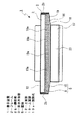
ヒートシンク配置凹部27b、27bにはそれぞれヒートシンク32、32が配置されている。ヒートシンク32は縦長に形成され、左右方向を向くベース面部32aと該ベース面部32aから外方(側方)へ突出されたフィン32b、32b、・・・とが一体に形成されて成り、該フィン32b、32b、・・・は前後方向において等間隔に並ぶように設けられている。
Heat sinks 32 and 32 are arranged in the heat sink arrangement recesses 27b and 27b, respectively. The
フィン32b、32b、・・・は、図10に示すように、上端が同一の高さに位置され、上下方向における長さが、前方に位置するもの程長くされている。従って、フィン32b、32b、・・・は、最も前方に位置するものが最長とされ、後方へ行くに従って順に長さが短くされ、最も後方に位置するものが最短とされている。
As shown in FIG. 10, the
ヒートシンク32、32のベース部32a、32aには図示しない熱伝導シートが貼付され、該熱伝導シートを介してそれぞれベース部32a、32aがパネルケース27の仕切板部27c、27cの外面に取り付けられている。従って、光源30a、30a、・・・及び制御回路基板30、30に発生した熱は、順に、熱伝導板、熱伝導シート、仕切板部27c、27c及び熱伝導シートを経由してヒートシンク32、32に伝達される。
A heat conductive sheet (not shown) is affixed to the
ヒートシンク32、32の最も後側に位置するフィン32b、32bには、その上端寄りの位置に、それぞれ熱伝導シート33、33が貼付されている(図9及び図10参照)。
インナーカバー7は熱伝導性の高い金属材料によって前方に開口された浅い箱状に形成されている(図2参照)。インナーカバー7は、図11乃至図15に示すように、背面壁部34と上面壁部35と側面壁部36、36と下面壁部37とを有している。
The
背面壁部34の後面の中央部には制御回路部38が設けられている(図2及び図7参照)。制御回路部38は表示パネル28の画像制御や各部の電源制御等を行う回路部であり、制御基板38aを有している。制御回路部38の側方には吸気ファン39が配置されている。
A
制御基板38a及び吸気ファン39は前方及び下方に開口されたカバー体40によって背面側から覆われ、該カバー体40は背面壁部34に取り付けられる(図11乃至図15参照)。カバー体40には吸気用又は排気用の複数の吸排気孔40a、40a、・・・が形成されている。
The
インナーカバー7の背面壁部34には吸気用又は排気用の空気流通孔34a、34a、・・・が形成され、上面壁部35の後端部には排気用孔35a、35a、・・・が形成され、下面壁部37の後端部には吸気用孔37a、37a、・・・が形成されている。
インナーカバー7の背面壁部34の上端寄りの位置には、その左右両端部にそれぞれ前方へ突出された接触突部34b、34bが設けられている(図9及び図10参照)。接触突部34b、34bは、インナーカバー7が液晶パネル部6に取り付けられた状態において、それぞれヒートシンク32、32に貼付された熱伝導シート33、33に接触される。
At the position near the upper end of the
背面壁部34の下端部には左右に延び後方に開口されたダクト溝41が形成されている。背面壁部34にはダクト溝41の左右両端部にそれぞれ連通する連通孔41a、41aが形成されている。連通孔41a、41aはインナーカバー7が液晶パネル部6に取り付けられた状態において、パネルケース27のヒートシンク配置凹部27b、27bにそれぞれ連通される。
A
背面壁部34にはダクト溝41を閉塞する吸気用カバー42が取り付けられている(図10及び図16参照)。吸気用カバー42は横長に形成され、中央部に送風入口42aが形成され、左右両端部がそれぞれ送風出口42b、42bとして形成されている。吸気用カバー42には送風入口42aの内側にファン43が配置されている。
An intake cover 42 that closes the
背面壁部34に吸気用カバー42が取り付けられることにより、ダクト溝41と吸気用カバー42とによって送風入口42aと送風出口42b、42bとの間に、冷却空気をヒートシンク32、32に送るダクト44が形成され、送風出口42b、42bは背面壁部34の連通孔41a、41aに連通される。従って、ダクト44はパネルケース27のヒートシンク配置凹部27b、27bに連通される。
By attaching the
インナーカバー7の上面壁部35には、その左右両端部にそれぞれ排気用切欠35b、35bが形成されている(図2及び図12参照)。排気用切欠35b、35bは、インナーカバー7が液晶パネル部6に取り付けられた状態において、それぞれパネルケース27のヒートシンク配置凹部27b、27bの上方に位置される。
背面カバー8には空気吸入孔8a、8a、・・・が形成されている(図1参照)。
表示本体部3は以下のようにして組み立てられる。
The display
液晶パネル部6の背面側からインナーカバー7が取り付けられる。インナーカバー7が取り付けられた状態においては、液晶パネル部6のパネルケース27の左右両側面部がインナーカバー7の側面壁部36、36に内側から接した状態とされる(図9参照)。従って、光源30a、30a、・・・及び制御回路基板30、30に発生した熱は、上記したように、ヒートシンク32、32に伝達される他、パネルケース27からインナーカバー7へ伝達されて外部へ放出される。
An
上記のように液晶パネル部6とインナーカバー7が結合された状態において、これらの両者を覆うようにしてフロントケース9とリアケース10が前後で結合され、リアケース10に吸気用カバー42が取り付けられた状態において背面カバー8がリアケース10の凹部17aを閉塞するように取り付けられることにより表示本体部3が組み立られる。
In the state where the liquid
表示本体部3は筐体5の側面部13、13、20、20が側板部2b、2bに接した状態でフレーム2に取り付けられ、該フレーム2に取り付けられた状態においてはフレーム2の内側に配置される(図1及び図3参照)。このときフレーム2の底板部2cに取り付けられた補助板4、4上に表示本体部3が載置される。
The display
表示本体部3がフレーム2の内側に取り付けられた状態においては、筐体5の上面とフレーム2の天板部2aとの間に隙間45が形成されると共に筐体5の下面とフレーム2の底板部2cとの間に隙間46が形成される。
In a state where the display
以上のように構成された表示装置1が駆動されると、表示パネル28に画像が表示される。このとき光源30a、30a、・・・からバックライトとしての光が出射され、光源30a、30a、・・・及び制御回路基板30に発生した熱は、上記したように、ヒートシンク32、32に伝達される他、パネルケース27からインナーカバー7へ伝達される。
When the
表示装置1の駆動時には、吸気用カバー42に設けられたファン43が回転され、外部の空気が背面カバー8の空気吸入孔8a、8a、・・・から送風入口42aを経てダクト44に冷却空気として取り込まれる。ダクト44に取り込まれた冷却空気は、送風出口42b、42bから連通孔41a、41aを通りパネルケース27のヒートシンク配置凹部27b、27bへ送られ、ヒートシンク32、32を冷却してリアケース10の放熱孔19a、19a、・・・から放出される。従って、光源30a、30a、・・・及び制御回路基板30、30に発生しヒートシンク32、32に伝達された熱が、この冷却空気によって放熱孔19a、19a、・・・から放出される。放熱孔19a、19aから放出された熱は、表示本体部3の上側の隙間45から空気中へ放出される。
When the
このとき表示本体部3の上側にはフレーム2の天板部2aが位置されているため、使用者がフレーム2の天板部2aに触れていたとしても、使用者に温度が上昇した冷却空気が吹き付けられるおそれがなく、また、天板部2aが極端に高温となることがないため、使用者の手に大量の熱が伝わるような不都合を回避することができる。
At this time, since the
また、表示本体部3の周囲に配置されるフレーム2を設けることにより、表示装置1の良好なデザイン性を確保することができる。
In addition, by providing the
さらに、外部の空気は表示本体部3の下側の隙間46から筐体5の吸気孔25a、25a、・・・からも冷却空気として筐体5の内部に取り込まれる。取り込まれた冷却空気は筐体5の内部に配置されている各部を冷却し、筐体5の放熱孔19a、19a、・・・を介して隙間45から外部へ放出される。
Further, outside air is also taken into the inside of the
同時に、表示装置1の駆動時には、カバー体40の内部に配置された吸気ファン39が回転され、外部の空気がリアケース10の吸気用穴24a、24a、・・・からカバー体40の吸排気孔40a、40a、・・・を介してカバー体40の内部に冷却空気として取り込まれる。カバー体40の内部に取り込まれた冷却空気は制御回路部38を冷却してカバー体40の吸排気孔40a、40a、・・・及びリアケース10の排気用穴24b、24b、・・・から外部へ放出される。
At the same time, when the
一方、表示装置1の駆動時には、スピーカー15、15から音声が出力されるが、この音声はスピーカー15、15の図示しない放音孔及び放音孔15a、15aから発せられる。このとき図示しない放音孔からは高音域及び中間音域の音声がフロントケース9の放音部11b、11bを介して前方へ向けて外部へ発せられ、放音孔15a、15aからは低音域の音声が筐体5の音声孔5a、5aを介して隙間46へ向けて下方へ発せられる。
On the other hand, when the
このように隙間46が形成されていることにより、低温域の音声を下方へ向けて発することができ、低音域の音声を強調することが可能である。また、隙間46を冷却空気を取り込むための空間の他、音声出力のための空間としても使用することができ、隙間46の有効活用を図ることができる。
Since the
表示装置1にあっては、ヒートシンク32、32をそれぞれ筐体5内の左右両側部に配置しているため、冷却空気を下方から上方へ流動させることができ、冷却効率の向上を図ることができる。
In the
また、外部の空気を冷却空気として取り込むファン43を設け、ダクト44によってヒートシンク32、32に冷却空気を送っているので、冷却空気が強制的にヒートシンク32、32に送られ、冷却効率の向上を図ることができる。
In addition, since the
さらに、ヒートシンク32、32の下端部をダクト44の送風出口42bから遠去かるに従って順に長くなるように形成しているため、ダクト44を介して送られる冷却空気がヒートシンク32、32の各フィン32b、32b、・・・間に効率的に供給され、冷却効率の一層の向上を図ることができる。
Furthermore, since the lower end portions of the heat sinks 32 and 32 are formed to become longer in order as they move away from the
尚、表示装置1にあっては、1つのファン43によって取り込んだ冷却空気をダクト44を経由させて左右のヒートシンク32、32に送っているので、ファン43と冷却空気の流路が折り曲げられる送風出口42b、42bとの距離が長く、ファン43による騒音の低減を図ることができる。
In the
また、表示装置1の駆動時には筐体5の背面部18の左右両端部に形成された吸気穴18a、18a、・・・から外部の空気が冷却空気としてパネルケース27のヒートシンク配置凹部27b、27bに取り込まれる。従って、ヒートシンク32、32の冷却効率の向上を図ることができる。
Further, when the
尚、上記には、ヒートシンク32、32を筐体5の左右両端部に配置した例を示したが、ヒートシンク32、32の配置位置は筐体5の左右両端部に限られることはない。
In addition, although the example which has arrange | positioned the heat sinks 32 and 32 in the left and right both ends of the housing | casing 5 was shown above, the arrangement position of the heat sinks 32 and 32 is not restricted to the right and left both ends of the housing |
また、ヒートシンク32、32に加え、例えば、別のヒートシンクをファン43の前側に対向した位置に配置し、このヒートシンクとヒートシンク32、32とを、例えば、ヒートパイプ等により連結して熱の移動を行うようにしてもよい。
Further, in addition to the heat sinks 32 and 32, for example, another heat sink is disposed at a position facing the front side of the
上記した最良の形態において示した各部の具体的な形状及び構造は、何れも本発明を実施する際の具体化のほんの一例を示したものにすぎず、これらによって本発明の技術的範囲が限定的に解釈されることがあってはならないものである。 The specific shapes and structures of the respective parts shown in the above-described best mode are merely examples of the implementation of the present invention, and the technical scope of the present invention is limited by these. It should not be interpreted in a general way.
1…表示装置、2a…天板部、2b…側板部、2c…底板部、3…表示本体部、5…筐体、12…上面部、13…側面部、14…下面部、15…スピーカー、15a…放音孔、19…上面部、19a…放熱孔、20…側面部、21…下面部、23…上面部、24…側面部、25…下面部、25a…吸気孔、28…表示パネル、30a…光源、31…リフレクター、32…ヒートシンク、32b…フィン、42a…送風入口、42b…送風出口、43…ファン、44…ダクト、45…隙間、46…隙間
DESCRIPTION OF
Claims (6)
光源を冷却し複数のフィンを有するヒートシンクと、
筐体の少なくとも上面部及び左右両側面部を外側から覆うように配置され上面部の上方に位置する天板部と左右両側面部のそれぞれ側方に位置する一対の側板部とを有するフレームとを備え、
上記筐体の上面部に少なくとも上記光源からヒートシンクに伝達される熱を放出する放熱孔を形成し、
上記フレームの天板部と筐体の上面部との間に放熱用の隙間を形成した
ことを特徴とする表示装置。 A display panel that is attached to the front side of the housing and displays an image, a light source that emits light as a backlight to the display panel, and a reflector that reflects the light emitted from the light source toward the display panel A display body,
A heat sink that cools the light source and has a plurality of fins;
A frame having a top plate portion that is disposed so as to cover at least the upper surface portion and the left and right side surface portions of the housing from the outside, and that has a pair of side plate portions that are respectively located on both sides of the left and right side surface portions. ,
A heat dissipation hole for releasing heat transmitted from the light source to the heat sink is formed on the upper surface of the housing,
A display device, wherein a gap for heat dissipation is formed between a top plate portion of the frame and an upper surface portion of the housing.
ことを特徴とする請求項1に記載の表示装置。 The display device according to claim 1, wherein the heat sink is disposed on both left and right sides of the housing.
一端部がファンに連結された送風入口とされ他端部がヒートシンクへ向けて冷却空気を送り込む送風出口とされると共にファンによって取り込んだ冷却空気をヒートシンクに送るダクトとを設けた
ことを特徴とする請求項1に記載の表示装置。 A fan that takes in external air as cooling air,
One end is an air inlet connected to the fan, the other end is an air outlet that sends cooling air toward the heat sink, and a duct that sends the cooling air taken in by the fan to the heat sink is provided. The display device according to claim 1.
ヒートシンクの長手方向における一端部をダクトの送風出口に対向して位置させ、
ヒートシンクの上記一端部における各フィンを送風出口から遠去かるに従って上記長手方向に長くなるように形成した
ことを特徴とする請求項3に記載の表示装置。 Place the heat sink so that the fins are aligned in the discharge direction of the cooling air from the air outlet of the duct,
One end in the longitudinal direction of the heat sink is positioned facing the air outlet of the duct,
The display device according to claim 3, wherein the fins at the one end of the heat sink are formed so as to become longer in the longitudinal direction as they move away from the air outlet.
筐体の少なくとも下面部及び左右両側面部を外側から覆うように配置され下面部の下方に位置する底板部と左右両側面部のそれぞれ側方に位置する一対の側板部とを有するフレームとを備え、
上記筐体の下面部に外部の空気を冷却空気として取り込む吸気孔を形成し、
上記フレームの底板部と筐体の下面部との間に吸気用の隙間を形成した
ことを特徴とする表示装置。 A display panel that is attached to the front side of the housing and displays an image, a light source that emits light as a backlight to the display panel, and a reflector that reflects the light emitted from the light source toward the display panel A display body,
A frame having a bottom plate portion that is disposed so as to cover at least the lower surface portion and the left and right side surface portions of the housing from the outside and is located below the lower surface portion and a pair of side plate portions that are respectively located on the sides of the left and right side surface portions;
Forming an intake hole for taking in external air as cooling air in the lower surface of the housing;
An air intake gap is formed between a bottom plate portion of the frame and a lower surface portion of the housing.
該スピーカーに下方に開口され少なくとも低温域の音声を出力する放音孔を形成した
ことを特徴とする請求項5に記載の表示装置。 A speaker is provided at the lower end of the housing,
The display device according to claim 5, wherein a sound emitting hole that opens downward in the speaker and outputs sound at least in a low temperature region is formed.
Priority Applications (2)
| Application Number | Priority Date | Filing Date | Title |
|---|---|---|---|
| JP2004291636A JP2006106272A (en) | 2004-10-04 | 2004-10-04 | Display apparatus |
| US11/236,561 US7259964B2 (en) | 2004-10-04 | 2005-09-28 | Display device |
Applications Claiming Priority (1)
| Application Number | Priority Date | Filing Date | Title |
|---|---|---|---|
| JP2004291636A JP2006106272A (en) | 2004-10-04 | 2004-10-04 | Display apparatus |
Publications (2)
| Publication Number | Publication Date |
|---|---|
| JP2006106272A true JP2006106272A (en) | 2006-04-20 |
| JP2006106272A5 JP2006106272A5 (en) | 2007-08-02 |
Family
ID=36124138
Family Applications (1)
| Application Number | Title | Priority Date | Filing Date |
|---|---|---|---|
| JP2004291636A Pending JP2006106272A (en) | 2004-10-04 | 2004-10-04 | Display apparatus |
Country Status (2)
| Country | Link |
|---|---|
| US (1) | US7259964B2 (en) |
| JP (1) | JP2006106272A (en) |
Cited By (13)
| Publication number | Priority date | Publication date | Assignee | Title |
|---|---|---|---|---|
| JP2008164802A (en) * | 2006-12-27 | 2008-07-17 | Sharp Corp | Display apparatus |
| JP2008197136A (en) * | 2007-02-08 | 2008-08-28 | Sharp Corp | Display device |
| JP2008286837A (en) * | 2007-05-15 | 2008-11-27 | Hitachi Ltd | Liquid crystal display device |
| WO2010004810A1 (en) * | 2008-07-09 | 2010-01-14 | 日本電気株式会社 | Liquid crystal display device |
| JP2011053258A (en) * | 2009-08-31 | 2011-03-17 | Panasonic Corp | Plasma display device |
| JP2011053257A (en) * | 2009-08-31 | 2011-03-17 | Panasonic Corp | Plasma display device |
| JP2011053259A (en) * | 2009-08-31 | 2011-03-17 | Panasonic Corp | Image display device |
| JP2011081808A (en) * | 2009-10-12 | 2011-04-21 | Pegatron Corp | Desktop personal computer |
| JP2011085903A (en) * | 2009-09-17 | 2011-04-28 | Panasonic Corp | Image display device |
| US8133650B2 (en) | 2007-11-21 | 2012-03-13 | Sk Chemicals Co., Ltd. | Polyester resin and toner including the same |
| JP2013122613A (en) * | 2013-02-05 | 2013-06-20 | Toshiba Corp | Electronic apparatus |
| KR20140098360A (en) * | 2013-01-31 | 2014-08-08 | 엘지디스플레이 주식회사 | Display device |
| US9091418B2 (en) | 2011-06-07 | 2015-07-28 | Sharp Kabushiki Kaisha | Display device and television receiver |
Families Citing this family (70)
| Publication number | Priority date | Publication date | Assignee | Title |
|---|---|---|---|---|
| KR20060070176A (en) * | 2004-12-20 | 2006-06-23 | 삼성전자주식회사 | Cooling apparatus and liquid crystal display device having the same |
| JPWO2006098365A1 (en) * | 2005-03-15 | 2008-08-28 | 松下電器産業株式会社 | Display device |
| TWM280095U (en) * | 2005-06-03 | 2005-11-01 | Innolux Display Corp | Heat sink |
| TW200735657A (en) * | 2006-03-06 | 2007-09-16 | Digimedia Technology Co Ltd | Liquid crystal television |
| KR20080033000A (en) * | 2006-10-12 | 2008-04-16 | 삼성전자주식회사 | Lens and backlight unit and liquid crystal display having the same |
| KR101315465B1 (en) | 2006-10-16 | 2013-10-04 | 삼성전자주식회사 | Cooling fan unit and display apparatus having the same |
| KR101183457B1 (en) * | 2006-10-16 | 2012-09-14 | 삼성전자주식회사 | Liquid Crystal Display And Control Method Thereof |
| TWI345661B (en) * | 2006-10-30 | 2011-07-21 | Coretronic Corp | Backlight module |
| KR101303892B1 (en) * | 2006-11-03 | 2013-09-05 | 삼성디스플레이 주식회사 | Backlight assembly and liquid crystal display having the same |
| KR100836489B1 (en) * | 2006-11-09 | 2008-06-09 | 삼성에스디아이 주식회사 | Portable Display Device |
| US20080222932A1 (en) * | 2007-03-09 | 2008-09-18 | Peng Yun | Display cabinet for light emitting diode lights and method of use |
| US7467882B2 (en) * | 2007-05-17 | 2008-12-23 | Kun-Jung Chang | Light-emitting diode heat-dissipating module |
| JP4333778B2 (en) * | 2007-05-23 | 2009-09-16 | 船井電機株式会社 | Equipment with built-in speakers, LCD television receiver |
| US8089582B2 (en) * | 2007-05-31 | 2012-01-03 | Hitachi Displays, Ltd. | Liquid crystal display device comprising at least one groove having an end portion that stops short of the non-adjacent opposite side surfaces and extends in a direction perpendicular to the non-adjacent side surfaces |
| TW200904178A (en) * | 2007-07-10 | 2009-01-16 | Coretronic Corp | The casing of display device |
| JP5111972B2 (en) * | 2007-08-07 | 2013-01-09 | 株式会社ジャパンディスプレイイースト | Liquid crystal display |
| US8854595B2 (en) | 2008-03-03 | 2014-10-07 | Manufacturing Resources International, Inc. | Constricted convection cooling system for an electronic display |
| US8654302B2 (en) | 2008-03-03 | 2014-02-18 | Manufacturing Resources International, Inc. | Heat exchanger for an electronic display |
| US8497972B2 (en) | 2009-11-13 | 2013-07-30 | Manufacturing Resources International, Inc. | Thermal plate with optional cooling loop in electronic display |
| US8693185B2 (en) | 2008-03-26 | 2014-04-08 | Manufacturing Resources International, Inc. | System and method for maintaining a consistent temperature gradient across an electronic display |
| JP5288889B2 (en) * | 2008-06-03 | 2013-09-11 | 三洋電機株式会社 | Image display device |
| JP2009296105A (en) * | 2008-06-03 | 2009-12-17 | Sanyo Electric Co Ltd | Image display device |
| CN102105832A (en) * | 2008-07-28 | 2011-06-22 | Nec显示器解决方案株式会社 | Display device |
| EP2166405A3 (en) * | 2008-09-18 | 2010-08-25 | Hitachi, Ltd. | Liquid crystal display unit |
| EP2187248A1 (en) * | 2008-11-18 | 2010-05-19 | Samsung Electronics Co., Ltd. | Backlight unit and liquid crystal display and TV device having the same |
| US8749749B2 (en) | 2008-12-18 | 2014-06-10 | Manufacturing Resources International, Inc. | System for cooling an electronic image assembly with manifolds and ambient gas |
| US10827656B2 (en) | 2008-12-18 | 2020-11-03 | Manufacturing Resources International, Inc. | System for cooling an electronic image assembly with circulating gas and ambient gas |
| TW201039506A (en) * | 2009-04-24 | 2010-11-01 | Au Optronics Corp | Shielding device and display device having the same |
| US8289715B2 (en) * | 2009-08-31 | 2012-10-16 | Panasonic Corporation | Plasma display device |
| JP2011171533A (en) * | 2010-02-19 | 2011-09-01 | Fujitsu Ltd | Electronic apparatus |
| CN102348341A (en) * | 2010-07-29 | 2012-02-08 | 鸿富锦精密工业(深圳)有限公司 | Electronic device shell and electronic device adopting same |
| JP4945668B2 (en) * | 2010-08-11 | 2012-06-06 | 株式会社東芝 | Display device and manufacturing method of display device |
| JP5200146B2 (en) * | 2011-09-29 | 2013-05-15 | 株式会社東芝 | Electronics |
| GB2503407B (en) * | 2011-10-10 | 2015-12-09 | Control Tech Ltd | Barrier device |
| TW201317676A (en) * | 2011-10-20 | 2013-05-01 | Wistron Corp | Display device with heat dissipating structures and electronic device using the same |
| US9621838B2 (en) * | 2011-10-25 | 2017-04-11 | Funai Electric Co., Ltd. | Display device and television apparatus |
| JP2013101203A (en) * | 2011-11-08 | 2013-05-23 | Funai Electric Co Ltd | Display device and television device |
| US9752753B2 (en) * | 2012-03-14 | 2017-09-05 | Samsung Display Co., Ltd. | Display device comprising the same |
| EP2701475A1 (en) * | 2012-08-22 | 2014-02-26 | Ruf Telematik AG | Housing for holding a flat screen |
| JP5960044B2 (en) * | 2012-12-26 | 2016-08-02 | 船井電機株式会社 | Display device |
| BR112015014834A2 (en) | 2012-12-28 | 2017-07-11 | Sony Corp | display device |
| WO2014150036A1 (en) | 2013-03-15 | 2014-09-25 | Manufacturing Resources International, Inc. | Cooling system for an electronic display |
| US9648790B2 (en) | 2013-03-15 | 2017-05-09 | Manufacturing Resources International, Inc. | Heat exchanger assembly for an electronic display |
| JP6236876B2 (en) * | 2013-05-24 | 2017-11-29 | 船井電機株式会社 | Display device |
| AU2014287438B2 (en) | 2013-07-08 | 2017-09-28 | Manufacturing Resources International, Inc. | Figure eight closed loop cooling system for electronic display |
| ES2733122T3 (en) | 2014-04-30 | 2019-11-27 | Mri Inc | Terraced electronic display set |
| JP6413531B2 (en) * | 2014-09-12 | 2018-10-31 | ティアック株式会社 | Aircraft regenerator |
| US9723765B2 (en) | 2015-02-17 | 2017-08-01 | Manufacturing Resources International, Inc. | Perimeter ventilation system for electronic display |
| GB2545199A (en) * | 2015-12-08 | 2017-06-14 | Esc Digital Media Ltd | Video display apparatus |
| ES2909480T3 (en) | 2016-03-04 | 2022-05-06 | Mri Inc | Cooling system for double-sided display assembly |
| KR102183007B1 (en) * | 2016-12-23 | 2020-11-25 | 삼성전자주식회사 | Display apparatus |
| CA3059972C (en) | 2017-04-27 | 2022-01-11 | Manufacturing Resources International, Inc. | System and method for preventing display bowing |
| US10485113B2 (en) | 2017-04-27 | 2019-11-19 | Manufacturing Resources International, Inc. | Field serviceable and replaceable display |
| US10502890B2 (en) * | 2017-12-29 | 2019-12-10 | Huizhou China Star Optoelectronics Technology Co., Ltd. | Display device and wall-mounted heat dissipation mechanism thereof |
| US10602626B2 (en) | 2018-07-30 | 2020-03-24 | Manufacturing Resources International, Inc. | Housing assembly for an integrated display unit |
| CN111316193B (en) | 2018-09-18 | 2023-09-15 | 谷歌有限责任公司 | display assistant device |
| CN112262358A (en) * | 2018-10-08 | 2021-01-22 | 谷歌有限责任公司 | Fall protection for display assistant device |
| TWI683158B (en) * | 2018-10-23 | 2020-01-21 | 友達光電股份有限公司 | Illumination device and liquid crystal display module thereof |
| US11096317B2 (en) | 2019-02-26 | 2021-08-17 | Manufacturing Resources International, Inc. | Display assembly with loopback cooling |
| US10795413B1 (en) | 2019-04-03 | 2020-10-06 | Manufacturing Resources International, Inc. | Electronic display assembly with a channel for ambient air in an access panel |
| CN110187541B (en) * | 2019-06-14 | 2024-03-22 | 上海启钧电子有限公司 | Display apparatus |
| KR20210009716A (en) * | 2019-07-17 | 2021-01-27 | 엘지전자 주식회사 | Display device |
| US11477923B2 (en) | 2020-10-02 | 2022-10-18 | Manufacturing Resources International, Inc. | Field customizable airflow system for a communications box |
| US11470749B2 (en) | 2020-10-23 | 2022-10-11 | Manufacturing Resources International, Inc. | Forced air cooling for display assemblies using centrifugal fans |
| US11778757B2 (en) | 2020-10-23 | 2023-10-03 | Manufacturing Resources International, Inc. | Display assemblies incorporating electric vehicle charging equipment |
| US11966263B2 (en) | 2021-07-28 | 2024-04-23 | Manufacturing Resources International, Inc. | Display assemblies for providing compressive forces at electronic display layers |
| US11744054B2 (en) | 2021-08-23 | 2023-08-29 | Manufacturing Resources International, Inc. | Fan unit for providing improved airflow within display assemblies |
| US11919393B2 (en) | 2021-08-23 | 2024-03-05 | Manufacturing Resources International, Inc. | Display assemblies inducing relatively turbulent flow and integrating electric vehicle charging equipment |
| US11762231B2 (en) | 2021-08-23 | 2023-09-19 | Manufacturing Resources International, Inc. | Display assemblies inducing turbulent flow |
| US11968813B2 (en) | 2021-11-23 | 2024-04-23 | Manufacturing Resources International, Inc. | Display assembly with divided interior space |
Citations (12)
| Publication number | Priority date | Publication date | Assignee | Title |
|---|---|---|---|---|
| JPH02101675U (en) * | 1989-01-31 | 1990-08-13 | ||
| JPH09238293A (en) * | 1996-02-29 | 1997-09-09 | Hitachi Ltd | Liquid crystal display device |
| JPH11259011A (en) * | 1998-03-16 | 1999-09-24 | Hitachi Ltd | Thin type display device |
| JPH11338372A (en) * | 1998-03-16 | 1999-12-10 | Hitachi Ltd | Thin type display device |
| JP2000010501A (en) * | 1998-06-18 | 2000-01-14 | Sony Corp | Mounting structure for panel type display device |
| JP2000270941A (en) * | 1999-03-26 | 2000-10-03 | I D K Design Kenkyusho:Kk | Cabinet for display device |
| JP2000338603A (en) * | 1999-05-28 | 2000-12-08 | Matsushita Electric Ind Co Ltd | Cooling device |
| JP2001216807A (en) * | 2000-01-31 | 2001-08-10 | Toshiba Corp | Direct-underlying backlight |
| JP2001265235A (en) * | 2000-03-15 | 2001-09-28 | Nec Corp | Light source device and liquid crystal display device using the same |
| JP2003075858A (en) * | 2001-08-31 | 2003-03-12 | Matsushita Electric Works Ltd | Heat radiation structure of wall-buried type liquid crystal panel unit |
| JP2003241673A (en) * | 2002-02-14 | 2003-08-29 | Matsushita Electric Ind Co Ltd | Planar display support device |
| JP2004233791A (en) * | 2003-01-31 | 2004-08-19 | Toshiba Corp | Electronic equipment and refrigeration unit used therein |
Family Cites Families (11)
| Publication number | Priority date | Publication date | Assignee | Title |
|---|---|---|---|---|
| JP2000172191A (en) * | 1998-12-04 | 2000-06-23 | Fujitsu Ltd | Planar display device |
| JP2001264754A (en) * | 2000-03-15 | 2001-09-26 | Nec Corp | Liquid crystal display device and light source device used for the same |
| JP4310039B2 (en) * | 2000-09-29 | 2009-08-05 | エーユー オプトロニクス コーポレイション | IC heat dissipation structure and display device |
| US7164224B2 (en) * | 2000-12-14 | 2007-01-16 | Sharp Kabushiki Kaisha | Backlight having discharge tube, reflector and heat conduction member contacting discharge tube |
| US6825828B2 (en) * | 2001-02-23 | 2004-11-30 | General Digital Corporation | Backlit LCD monitor |
| JP3994704B2 (en) * | 2001-09-11 | 2007-10-24 | セイコーエプソン株式会社 | Liquid crystal display |
| JP4083659B2 (en) * | 2002-10-10 | 2008-04-30 | バルコ・ナムローゼ・フエンノートシャップ | Panel display and tiled display |
| TW577684U (en) * | 2003-06-30 | 2004-02-21 | Malico Inc | Heat dissipation module of flat display device |
| US20050073639A1 (en) * | 2003-10-06 | 2005-04-07 | Shin-Tung Pan | Heat dissipating structure of liquid crystal display |
| TWI285773B (en) * | 2004-07-07 | 2007-08-21 | Au Optronics Corp | Cooling-fastening device and method for cooling |
| US7072179B1 (en) * | 2004-09-10 | 2006-07-04 | Micro Industries Corporation | Fanless computer with integrated display |
-
2004
- 2004-10-04 JP JP2004291636A patent/JP2006106272A/en active Pending
-
2005
- 2005-09-28 US US11/236,561 patent/US7259964B2/en not_active Expired - Fee Related
Patent Citations (12)
| Publication number | Priority date | Publication date | Assignee | Title |
|---|---|---|---|---|
| JPH02101675U (en) * | 1989-01-31 | 1990-08-13 | ||
| JPH09238293A (en) * | 1996-02-29 | 1997-09-09 | Hitachi Ltd | Liquid crystal display device |
| JPH11259011A (en) * | 1998-03-16 | 1999-09-24 | Hitachi Ltd | Thin type display device |
| JPH11338372A (en) * | 1998-03-16 | 1999-12-10 | Hitachi Ltd | Thin type display device |
| JP2000010501A (en) * | 1998-06-18 | 2000-01-14 | Sony Corp | Mounting structure for panel type display device |
| JP2000270941A (en) * | 1999-03-26 | 2000-10-03 | I D K Design Kenkyusho:Kk | Cabinet for display device |
| JP2000338603A (en) * | 1999-05-28 | 2000-12-08 | Matsushita Electric Ind Co Ltd | Cooling device |
| JP2001216807A (en) * | 2000-01-31 | 2001-08-10 | Toshiba Corp | Direct-underlying backlight |
| JP2001265235A (en) * | 2000-03-15 | 2001-09-28 | Nec Corp | Light source device and liquid crystal display device using the same |
| JP2003075858A (en) * | 2001-08-31 | 2003-03-12 | Matsushita Electric Works Ltd | Heat radiation structure of wall-buried type liquid crystal panel unit |
| JP2003241673A (en) * | 2002-02-14 | 2003-08-29 | Matsushita Electric Ind Co Ltd | Planar display support device |
| JP2004233791A (en) * | 2003-01-31 | 2004-08-19 | Toshiba Corp | Electronic equipment and refrigeration unit used therein |
Cited By (17)
| Publication number | Priority date | Publication date | Assignee | Title |
|---|---|---|---|---|
| JP2008164802A (en) * | 2006-12-27 | 2008-07-17 | Sharp Corp | Display apparatus |
| JP2008197136A (en) * | 2007-02-08 | 2008-08-28 | Sharp Corp | Display device |
| JP2008286837A (en) * | 2007-05-15 | 2008-11-27 | Hitachi Ltd | Liquid crystal display device |
| JP4516582B2 (en) * | 2007-05-15 | 2010-08-04 | 株式会社日立製作所 | Liquid crystal display |
| US8133650B2 (en) | 2007-11-21 | 2012-03-13 | Sk Chemicals Co., Ltd. | Polyester resin and toner including the same |
| JP5234110B2 (en) * | 2008-07-09 | 2013-07-10 | 日本電気株式会社 | Liquid crystal display |
| WO2010004810A1 (en) * | 2008-07-09 | 2010-01-14 | 日本電気株式会社 | Liquid crystal display device |
| US8514364B2 (en) | 2008-07-09 | 2013-08-20 | Nec Corporation | Dust and dirt resistant liquid crystal display device |
| JP2011053257A (en) * | 2009-08-31 | 2011-03-17 | Panasonic Corp | Plasma display device |
| JP2011053259A (en) * | 2009-08-31 | 2011-03-17 | Panasonic Corp | Image display device |
| JP2011053258A (en) * | 2009-08-31 | 2011-03-17 | Panasonic Corp | Plasma display device |
| JP2011085903A (en) * | 2009-09-17 | 2011-04-28 | Panasonic Corp | Image display device |
| JP2011081808A (en) * | 2009-10-12 | 2011-04-21 | Pegatron Corp | Desktop personal computer |
| US9091418B2 (en) | 2011-06-07 | 2015-07-28 | Sharp Kabushiki Kaisha | Display device and television receiver |
| KR20140098360A (en) * | 2013-01-31 | 2014-08-08 | 엘지디스플레이 주식회사 | Display device |
| KR102084609B1 (en) | 2013-01-31 | 2020-03-04 | 엘지디스플레이 주식회사 | Display device |
| JP2013122613A (en) * | 2013-02-05 | 2013-06-20 | Toshiba Corp | Electronic apparatus |
Also Published As
| Publication number | Publication date |
|---|---|
| US7259964B2 (en) | 2007-08-21 |
| US20060070280A1 (en) | 2006-04-06 |
Similar Documents
| Publication | Publication Date | Title |
|---|---|---|
| JP2006106272A (en) | Display apparatus | |
| KR100688978B1 (en) | Image projecting apparatus | |
| JP4656418B2 (en) | Lighting device and image display device | |
| JP2005331945A (en) | Plasma display display | |
| JP2009192728A (en) | Display device | |
| US20210033916A1 (en) | Display apparatus | |
| JP6159783B2 (en) | Electronics | |
| RU2002107437A (en) | Electronic device with heat-generating components and heat-absorbing elements | |
| JP2000003137A (en) | Plasma display device | |
| JP2010016957A (en) | Inverter apparatus | |
| JP4659466B2 (en) | Projection display | |
| JP2003057754A (en) | Cooler and projector provided with it | |
| JP2007052950A (en) | Light emitting diode lighting system and image display device | |
| JP2018092755A (en) | Radiation device | |
| WO2007029349A1 (en) | Light source device, lamp housing, lamp unit, and projection type image display device | |
| JP2004139186A5 (en) | ||
| JP7032997B2 (en) | Display device and television receiver | |
| JPH11355623A (en) | Heat dissipating device for video camera | |
| CN208188559U (en) | A kind of cooling system and laser-projector | |
| JPH10173371A (en) | Housing structure of electronic apparatus | |
| WO2019163555A1 (en) | Image display device | |
| TWI623803B (en) | Projector | |
| CN112243334A (en) | Heat radiation structure of heating component | |
| JP2009231193A (en) | Lighting system, and liquid crystal display | |
| JP2012254185A (en) | Light source device for endoscope |
Legal Events
| Date | Code | Title | Description |
|---|---|---|---|
| A521 | Written amendment |
Free format text: JAPANESE INTERMEDIATE CODE: A523 Effective date: 20070618 |
|
| A621 | Written request for application examination |
Free format text: JAPANESE INTERMEDIATE CODE: A621 Effective date: 20070618 |
|
| A977 | Report on retrieval |
Free format text: JAPANESE INTERMEDIATE CODE: A971007 Effective date: 20100629 |
|
| A131 | Notification of reasons for refusal |
Free format text: JAPANESE INTERMEDIATE CODE: A131 Effective date: 20100916 |
|
| A521 | Written amendment |
Free format text: JAPANESE INTERMEDIATE CODE: A523 Effective date: 20101108 |
|
| A131 | Notification of reasons for refusal |
Free format text: JAPANESE INTERMEDIATE CODE: A131 Effective date: 20110407 |
|
| A02 | Decision of refusal |
Free format text: JAPANESE INTERMEDIATE CODE: A02 Effective date: 20110825 |