JP4659466B2 - Projection display - Google Patents
Projection display Download PDFInfo
- Publication number
- JP4659466B2 JP4659466B2 JP2005016791A JP2005016791A JP4659466B2 JP 4659466 B2 JP4659466 B2 JP 4659466B2 JP 2005016791 A JP2005016791 A JP 2005016791A JP 2005016791 A JP2005016791 A JP 2005016791A JP 4659466 B2 JP4659466 B2 JP 4659466B2
- Authority
- JP
- Japan
- Prior art keywords
- projection
- wall
- light source
- housing
- hollow
- Prior art date
- Legal status (The legal status is an assumption and is not a legal conclusion. Google has not performed a legal analysis and makes no representation as to the accuracy of the status listed.)
- Expired - Fee Related
Links
Images


Classifications
-
- G—PHYSICS
- G03—PHOTOGRAPHY; CINEMATOGRAPHY; ANALOGOUS TECHNIQUES USING WAVES OTHER THAN OPTICAL WAVES; ELECTROGRAPHY; HOLOGRAPHY
- G03B—APPARATUS OR ARRANGEMENTS FOR TAKING PHOTOGRAPHS OR FOR PROJECTING OR VIEWING THEM; APPARATUS OR ARRANGEMENTS EMPLOYING ANALOGOUS TECHNIQUES USING WAVES OTHER THAN OPTICAL WAVES; ACCESSORIES THEREFOR
- G03B21/00—Projectors or projection-type viewers; Accessories therefor
- G03B21/10—Projectors with built-in or built-on screen
-
- G—PHYSICS
- G03—PHOTOGRAPHY; CINEMATOGRAPHY; ANALOGOUS TECHNIQUES USING WAVES OTHER THAN OPTICAL WAVES; ELECTROGRAPHY; HOLOGRAPHY
- G03B—APPARATUS OR ARRANGEMENTS FOR TAKING PHOTOGRAPHS OR FOR PROJECTING OR VIEWING THEM; APPARATUS OR ARRANGEMENTS EMPLOYING ANALOGOUS TECHNIQUES USING WAVES OTHER THAN OPTICAL WAVES; ACCESSORIES THEREFOR
- G03B21/00—Projectors or projection-type viewers; Accessories therefor
- G03B21/14—Details
- G03B21/145—Housing details, e.g. position adjustments thereof
-
- G—PHYSICS
- G03—PHOTOGRAPHY; CINEMATOGRAPHY; ANALOGOUS TECHNIQUES USING WAVES OTHER THAN OPTICAL WAVES; ELECTROGRAPHY; HOLOGRAPHY
- G03B—APPARATUS OR ARRANGEMENTS FOR TAKING PHOTOGRAPHS OR FOR PROJECTING OR VIEWING THEM; APPARATUS OR ARRANGEMENTS EMPLOYING ANALOGOUS TECHNIQUES USING WAVES OTHER THAN OPTICAL WAVES; ACCESSORIES THEREFOR
- G03B21/00—Projectors or projection-type viewers; Accessories therefor
- G03B21/14—Details
- G03B21/16—Cooling; Preventing overheating
Landscapes
- Physics & Mathematics (AREA)
- General Physics & Mathematics (AREA)
- Projection Apparatus (AREA)
Description
本発明は、投射型表示装置に関する。 The present invention relates to a projection display device.
より具体的には光源から生じる熱を放熱させるための技術に関する。 More specifically, the present invention relates to a technique for dissipating heat generated from a light source.
図13は、投射型表示装置D5の構成を示した概略図である。 FIG. 13 is a schematic diagram showing the configuration of the projection display device D5.
符号5は全反射ミラー、6はスクリーン、50は筐体、そして20は投射ユニットである。 Reference numeral 5 is a total reflection mirror, 6 is a screen, 50 is a housing, and 20 is a projection unit.
図14は、投射ユニット20の構成を示した概略図である。
FIG. 14 is a schematic diagram illustrating the configuration of the
前記投射ユニット20は、投射ランプ1、冷却ファン2、ライトバルブ3および投射レンズ4を含み、光源である前記投射ランプ1からの投射光を前記ライトバルブ3で変調し、前記投射レンズ4によってスクリーン6に対して拡大投射を行う。
The
ここで、前記投射ユニット20は、前記冷却ファン2の為の吸気口201および前記冷却ファン2への開口部を除き、密閉構造としている。
Here, the
尚、図14においては、説明の為、前記投射ユニット20は、上面を開口した図を示している。
In FIG. 14, for the sake of explanation, the
投射ランプとして、ショートアーク型の超高圧水銀ランプ等が多く使用される。 As a projection lamp, a short arc type ultra-high pressure mercury lamp or the like is often used.
ところで投射ランプは非常に高温になる。特に投射ランプを構成する発光管、リフレクタ共に非常に高温になる。 By the way, the projection lamp becomes very hot. In particular, both the arc tube and the reflector constituting the projection lamp become extremely hot.
図13に示すように、投射ユニット20においても、前記投射ランプ1の近傍に前記冷却ファン2を配置し、さらに吸気口201を形成することで、前記冷却ファン2によって、前記投射ランプ1を冷却し、温度が上昇した熱気を前記投射ユニット20の外部へと排気する構成となっている。
As shown in FIG. 13, also in the
投射ランプの冷却方法として、冷却ファンを用いた特許文献1や特許文献2がある。
図14に示すように、A1は前記吸気口201から吸気することで発生させた冷却風であるが、冷却風A1は前記投射ランプ1を冷却した後、温度が上昇した熱気A2となる。
As shown in FIG. 14, A1 is the cooling air generated by sucking air from the
上述したように熱気を投射ユニット20外部へと排気するということは筐体50内に排出することになりその結果筐体内の温度が上昇し、該筐体50内に配置されている他の部品を加熱することになり性能に影響を及ぼす。また光学ユニットに投射ランプと共に配置されているライトバルブ3にも熱を与えてしまうことになる。
As described above, exhausting hot air to the outside of the
その為、本発明者はこれまでに投射ランプ1を冷却した熱気A2を、前記投射ユニット20から直接、該筐体50に設置した排気口(不図示)を経由して装置外へと排出することを試みていた。
Therefore, the present inventor discharges the hot air A2 that has cooled the
また、その際、該筐体50内の温度を上昇させず、筐体50の排気口の位置を任意に設定する為に、排気ダクト22を用いて、前記熱気A2を該装置外へと排気する構成とした装置を検討した。
At that time, in order to arbitrarily set the position of the exhaust port of the
しかしながら、この熱気A2によって、該筐体50の排気口近傍に存在する物体(例えば接地室内の壁や家具や机や該装置にてプレゼンテーション等を行う人間等)を高温に暖めてしまう可能性がある。
However, there is a possibility that this hot air A2 warms an object (for example, a wall in the grounded room, furniture, a desk, a person who makes a presentation on the device, etc.) near the exhaust port of the
よって本発明は光源が生じる熱を筐体内の物品の性能に影響を与えることなく放熱でき且つ装置外近傍の物体を高温に暖めることが無い投射型表示装置を提供することを目的とする。 Accordingly, an object of the present invention is to provide a projection display device that can dissipate heat generated by a light source without affecting the performance of an article in a housing and that does not warm an object in the vicinity of the outside of the device to a high temperature.
よって本発明は、筺体内に光源とライトバルブと投射光学系と反射ミラーとスクリーンとを有する投射型表示装置において、
前記反射ミラーは前記投射光学系から投射された光をスクリーンへ折り返すためのミラーであり、
前記筺体の少なくとも一部が中空壁であり、前記中空壁は前記光源が生じる熱を放熱する放熱壁であり、
前記光源が生じる前記熱を含む熱風を前記中空壁の中空部へ導くための導風路を有し、
前記中空部へ導くための導風路は前記反射ミラーを有する空間を介さずに前記中空壁の中空部に前記熱風を導く導風路であり、
前記中空壁において放熱された風を再び前記光源へ導くための導風路を更に有し、 前記光源へ導くための導風路は前記反射ミラーを有する空間を介さずに前記光源へ前記風を導く導風路であることを特徴とする投射型表示装置を提供する。
The invention thus provides, in a projection display apparatus having a light source and a light valve and the projection optical system and the reflecting mirror and the screen in the casing,
The reflection mirror is a mirror for turning back the light projected from the projection optical system to the screen,
At least a part of the housing is a hollow wall, and the hollow wall is a heat radiating wall that radiates heat generated by the light source,
An air guide path for guiding the hot air containing the heat generated by the light source to the hollow portion of the hollow wall;
The air guide path for guiding to the hollow part is an air guide path for guiding the hot air to the hollow part of the hollow wall without going through the space having the reflection mirror,
The air guide path for a further perforated for guiding the hollow wall again said light source radiating winds in, air guide path for guiding to the light source of the air to the light source without passing through the space with the reflective mirror Provided is a projection type display device characterized by being a guiding air guide .
本発明によれば、
光源が生じる熱を筐体内の物品の性能に影響を与えることなく放熱でき且つ装置外近傍の物体を高温に暖めることが無い投射型表示装置を提供することが出来る。
According to the present invention,
It is possible to provide a projection display device that can radiate the heat generated by the light source without affecting the performance of the article in the housing and does not warm an object near the outside to a high temperature.
本発明は、筺体内に光源とライトバルブと投射光学系と反射ミラーとスクリーンとを有する投射型表示装置において、
前記反射ミラーは前記投射光学系から投射された光をスクリーンへ折り返すためのミラーであり、
前記筺体の少なくとも一部が中空壁であり、前記中空壁は前記光源が生じる熱を放熱する放熱壁であり、
前記光源が生じる前記熱を含む熱風を前記中空壁の中空部へ導くための導風路を有し、
前記中空部へ導くための導風路は前記反射ミラーを有する空間を介さずに前記中空壁の中空部に前記熱風を導く導風路であり、
前記中空壁において放熱された風を再び前記光源へ導くための導風路を更に有し、 前記光源へ導くための導風路は前記反射ミラーを有する空間を介さずに前記光源へ前記風を導く導風路であることを特徴とする投射型表示装置である。
The present invention, in the projection type display device having a light source and a light valve and the projection optical system and the reflecting mirror and the screen in the casing,
The reflection mirror is a mirror for turning back the light projected from the projection optical system to the screen,
At least a part of the housing is a hollow wall, and the hollow wall is a heat radiating wall that radiates heat generated by the light source,
An air guide path for guiding the hot air containing the heat generated by the light source to the hollow portion of the hollow wall;
The air guide path for guiding to the hollow part is an air guide path for guiding the hot air to the hollow part of the hollow wall without going through the space having the reflection mirror,
The air guide path for a further perforated for guiding the hollow wall again said light source radiating winds in, air guide path for guiding to the light source of the air to the light source without passing through the space with the reflective mirror It is a projection type display device characterized in that it is a wind guide path .
本発明者は次のことに気づいた。 The inventor has noticed the following.
筐体外に熱風を排出する場合、排出された熱は投射型表示装置外において吸収される。 When hot air is discharged outside the housing, the discharged heat is absorbed outside the projection display device.
その際排出口付近は熱風の排出により暖められてられており、その暖められる領域は排出口直近傍に限られる。 At that time, the vicinity of the discharge port is warmed by the discharge of hot air, and the warmed area is limited to the vicinity of the discharge port.
そしてその原因を検討したところ、筐体壁が一枚の密な壁であるためであることに気づいた。 And when examining the cause, I realized that it was because the housing wall was a single dense wall.
即ち本発明では筐体の壁を中空壁とすることに注目した。 That is, in the present invention, attention is paid to the fact that the wall of the casing is a hollow wall.
光源からの熱風を中空壁の中空部に通過させれば、中空部を構成する壁のうち筐体内部側の壁により熱が筐体内に伝わることを防ぐことが出来、筐体外部側の壁により熱が装置外部の物体を高温に暖めることを防ぐことが出来る。 If hot air from the light source is passed through the hollow part of the hollow wall, it is possible to prevent heat from being transferred into the casing by the wall inside the casing among the walls constituting the hollow part, and the wall on the outer side of the casing This prevents heat from warming the object outside the apparatus to a high temperature.
より具体的にいえば次のような利点がある。 More specifically, there are the following advantages.
筐体壁は広い面を有している。即ち筐体外部の側の壁面を広く放熱に使うことで装置近傍の物体を高温に暖めることが防ぐことが出来る。投射型表示装置は筐体面が広いのでその広い面を自在に利用することが出来る。 The housing wall has a wide surface. That is, it is possible to prevent an object in the vicinity of the apparatus from being heated to a high temperature by widely using the wall surface on the outside of the housing for heat dissipation. Since the projection display device has a wide housing surface, the wide surface can be used freely.
例えば放熱板を一枚の密な板状の壁として装置の外部に配置してもよいが、その場合意匠的に即ち美観的に配置位置や形状を更に考慮しなければならない。また放熱板を配置することによって装置全体が大きくなってしまう。これに対して本実施形態の投射型表示装置の場合、壁自体が放熱壁である中空壁であるのでそのような放熱板の機能を壁が有するので装置を大きくする必要が無い。 For example, the heat radiating plate may be arranged outside the apparatus as a single dense plate-like wall, but in that case, the arrangement position and shape must be further considered in terms of design, that is, aesthetically. Moreover, the whole apparatus will become large by arrange | positioning a heat sink. On the other hand, in the case of the projection type display device of this embodiment, since the wall itself is a hollow wall which is a heat radiating wall, the wall has the function of such a heat radiating plate, so there is no need to enlarge the device.
本実施形態に係る投射型表示装置において中空壁が配置される位置は筐体壁の何れの位置でも構わない。例えば筐体全体が中空壁でもよくあるいは放熱壁として機能させたい個所を中空壁とし、それ以外を一枚の密の壁とする構成でも良い。 In the projection display device according to the present embodiment, the position where the hollow wall is disposed may be any position on the housing wall. For example, the entire housing may be a hollow wall, or a portion that is desired to function as a heat radiating wall may be a hollow wall, and the other portion may be a single dense wall.
本実施形態に係る投射型表示装置の筐体壁として好ましい壁は、筐体内側に面する壁と筐体外側に面する壁との間に間仕切りが設けられている構成の壁が好ましい。そのような構成にすることにより筐体内側に面する壁と筐体外側に面する壁との間での強度が増すからである。 A wall preferable as a housing wall of the projection display device according to the present embodiment is preferably a wall having a partition provided between a wall facing the inside of the housing and a wall facing the outside of the housing. This is because such a configuration increases the strength between the wall facing the inside of the housing and the wall facing the outside of the housing.
より具体的には押出型材を筐体壁とすることが好ましい。その場合筐体壁の中空部を自在に成形することが出来る。 More specifically, it is preferable that the extrusion mold material is a housing wall. In that case, the hollow part of the housing wall can be formed freely.
本実施形態に係る投射型表示装置の筐体の素材として金属を用いることが出来る。 Metal can be used as the material of the housing of the projection display device according to the present embodiment.
より好ましくはアルミニウムである。アルミニウムは軽量かつ熱伝導率が高く放熱効果が良好であるため好ましい。更に押出型材として得られる筐体としてもアルミニウムは好ましく用いられる素材である。 More preferably, it is aluminum. Aluminum is preferable because it is lightweight and has high thermal conductivity and good heat dissipation effect. Furthermore, aluminum is a material preferably used as a casing obtained as an extrusion mold material.
本実施形態に係る投射型表示装置は熱風を装置外に排出するための開口を有しても良い。その場合熱風は開口から装置外に排出される途中の中空壁の筐体外側に面する壁により放熱が装置外部に対して一部行われるので開口を出た際の熱風の温度は下げられている。 The projection display device according to the present embodiment may have an opening for discharging hot air to the outside of the device. In that case, the heat air is partly radiated to the outside of the device by the wall facing the outside of the housing of the hollow wall in the middle of being exhausted from the opening to the outside of the device, so the temperature of the hot air when leaving the opening is lowered Yes.
また本実施形態に係る投射型表示装置は、
光源が生じる熱を含む熱風を中空壁の中空部へ導くための導風路を有し、
中空壁において放熱された風を再び光源へ導くための導風路を有し、
両導風路と中空壁との間で連通された領域は筐体外部に対して閉鎖されている構成でも良い。即ち熱風を光源から中空壁へ送りそこで冷却させ、装置外に排出させること無く再び筐体に戻して筐体内の物品(例えば光源)を冷却させるようにすることが出来る。この場合風が装置外部に対して開放されていないので、装置外部における風による騒音が大幅に低減される。あるいは外部からの空気を取り込まなくて済むので筐体内へのダストの侵入を防ぐことが出来る。
In addition, the projection display device according to this embodiment is
An air guide path for guiding hot air containing heat generated by the light source to the hollow portion of the hollow wall;
Having a wind guide path for guiding the heat radiated in the hollow wall to the light source again,
The area | region connected between both the air ducts and the hollow wall may be the structure closed with respect to the housing | casing exterior. That is, hot air can be sent from the light source to the hollow wall, cooled there, and returned to the housing again without being discharged out of the apparatus, thereby cooling an article (for example, a light source) in the housing. In this case, since the wind is not open to the outside of the apparatus, noise due to the wind outside the apparatus is greatly reduced. Alternatively, since it is not necessary to take in air from the outside, it is possible to prevent dust from entering the housing.
以上説明したように本実施形態にかかわる投射型表示装置は光源が生じる熱を筐体内の物品の性能に影響を与えることなく放熱でき且つ装置外近傍の物体を高温に暖めることが無くしたがって設置位置の自由度が増した投射型表示装置を提供することが出来る。 As described above, the projection display apparatus according to the present embodiment can radiate the heat generated by the light source without affecting the performance of the article in the housing, and does not warm the object in the vicinity outside the apparatus to the high temperature. It is possible to provide a projection type display device with an increased degree of freedom.
なお後述の実施例においてダクトとは風を通過させる筐体壁のことであり中空壁のことである。 In the embodiments described later, the duct is a housing wall that allows air to pass through, and is a hollow wall.
(実施例1)
以下図1乃至図7を参照して、本発明の第一の実施例について説明する。
Example 1
Hereinafter, a first embodiment of the present invention will be described with reference to FIGS.
本実施例においては、投射ランプからの投射光を透過型液晶パネルで変調し、投射レンズでスクリーンに変調光を拡大投射する、背面投射型液晶プロジェクタ装置の例を示す。 In the present embodiment, an example of a rear projection type liquid crystal projector device in which projection light from a projection lamp is modulated by a transmissive liquid crystal panel and the modulated light is enlarged and projected onto a screen by a projection lens will be described.
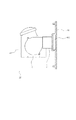
図1は、本発明の第一の実施例における投射型表示装置D1の構成を示した概略図である。 FIG. 1 is a schematic view showing the configuration of a projection display device D1 in the first embodiment of the present invention.
図1において、20は、投射ランプからの投射光をライトバルブで変調し、投射レンズで拡大投射を行う投射ユニットであり、5は前記投射ユニット20からの投射光L2を反射する全反射ミラー、6はスクリーン、60は該表示装置D1の筐体である。
In FIG. 1, 20 is a projection unit that modulates projection light from a projection lamp with a light valve and performs enlarged projection with a projection lens, and 5 is a total reflection mirror that reflects the projection light L2 from the
図2は、前記投射ユニット20の構成を示した概略図であり、前記投射ユニット20は、発光管101およびリフレクタ102で構成された投射ランプ1、冷却ファン2、透過型液晶パネルであるライトバルブ3および、投射レンズ4を含み、光源である前記投射ランプ1からの投射光L1を前記ライトバルブ3で変調し、前記投射レンズ4によってスクリーン6に対して拡大投射(L2)を行う。
FIG. 2 is a schematic diagram showing the configuration of the
前記投射ユニット20には、前記冷却ファン2によって前記投射ランプ1を冷却する為の吸気口201が設置される共に、前記冷却ファン2が前記投射ランプ1の近傍に配置され、前記吸気口201から吸気した冷却風が、前記投射ランプ1を通過し、前記冷却ファン2によって光学ユニット20から排出されるようにそれぞれ配置されている。
The
ここで、冷却ファン2は、吸気方向と排気方向が直交するシロッコファンを使用している。 Here, the cooling fan 2 uses a sirocco fan whose intake direction and exhaust direction are orthogonal to each other.
また、前記光学ユニット20は、前記冷却ファン2の為の吸気口201および前記冷却ファン2の開口部を除き、密閉構造としている。
The
前記投射ユニット20において、前記冷却ファン2によって前記吸気口201から吸気した冷却風A1は、前記投射ランプ1を冷却し、温度が上昇した熱気A2となる。
In the
前記筐体60の装置前面側には、その材質が熱伝導に優れた金属であるアルミニウム合金で、その断面形状がダクト形状611を含むように形成された押出型材61が、外壁部材として使用されている。
On the front side of the device of the
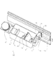
図3および図4、図5は、前記投射ユニット20と前記押出型材61の構成を示した概略図であり、図4は装置上面側から見た断面図、図5は装置側面から見た断面図を示している。
3, 4, and 5 are schematic views showing the configuration of the
但し、図3においては、説明の為、前記投射ユニット20は、上面を開口した図を示している。
However, in FIG. 3, the
図3および図4、図5において、前記ダクト形状611には、該装置内部側に開口部612が形成され、さらに該装置外部側には排気口613が形成されている。
3, 4, and 5, the
さらに、前記冷却ファン2の排気側と前記ダクト形状611の間は、前記開口部612を介して前記冷却ファン2の排気側と前記ダクト形状611を連通させるよう、導風ダクト21が設置されている。
Further, an
これにより、前記冷却ファン2から排出され、前記投射ランプ1を冷却し温度が上昇した熱気A2は、前記導風ダクト21を経由して前記ダクト形状611へと導風され、前記ダクト形状611内部を通過した後、前記排気口613から該装置外部へと排出されることとなる。
As a result, the hot air A2 discharged from the cooling fan 2 and having cooled the
ここで、前記導風ダクト21の、前記開口部612における前記ダクト形状611への接合部においては、前記熱気A2が、前記ダクト形状611に形成された前記排気口613方向に向かって流れるように、導風形状を形成すると良い。
Here, in the joint portion of the
また、前記冷却ファン2から、前記排気口613までの距離が長くなる為、前記冷却ファン2には、高静圧のシロッコファンを用いると良い。
Further, since the distance from the cooling fan 2 to the
本実施例の形態によれば、前記押出型材61は熱伝導率が高い金属の一つであるアルミニウム合金で形成されており、さらに外壁部材であるので、前記熱気A2の温度に対して低い温度の外気に面している。
According to the form of the present embodiment, the
つまり前記押出型材61は、前記熱気A2が通過する際に、その熱伝導効果によって、前記ダクト形状611内部を受熱面とし、前記外気に面している面を放熱面とした、放熱部材として作用する。
That is, when the hot air A2 passes, the extruded
これにより、前記熱気A2が前記排気口613から、該筐体60外部へと排出される際の温度は、前記冷却ファン2から排出された時点での温度と比較して低くなる為、該筐体60の前記排気口613近傍に設置された、他の構造物の温度を上昇させ損傷させる可能性や、前記排気口613近傍にいるユーザーに、不快感を与える可能性や火傷等を負わせる危険性等の問題点を低減する事が可能となる。
Accordingly, the temperature when the hot air A2 is discharged from the
尚、本実施例においては前記押出型材の材質としてアルミニウム合金を一例として挙げたが、これに限定されるものではなくマグネシウム合金等他の金属を使用しても良い。 In this embodiment, an aluminum alloy is used as an example of the material of the extrusion mold material. However, the present invention is not limited to this, and other metals such as a magnesium alloy may be used.
また、本実施例においては、装置前面側の外壁部材である押出型材61を使用し、前記排気口613を装置側面に配置しているが、これに限定されるものではなく、どの外壁面を使用しても良く、また、排気口の位置も任意に設定して良い。
Further, in this embodiment, the
さらに、複数の押出型材にダクト形状を形成して、ダクト形状部を連結しても良く、この場合は、少なくとも一つの押出型材を熱伝導率の高い金属を材料とすれば良い。 Furthermore, a duct shape may be formed in a plurality of extrusion mold materials and the duct shape portions may be connected. In this case, at least one extrusion mold material may be made of a metal having high thermal conductivity.
また、本発明は、背面投射型表示装置に限定されるものではなく、前面投射型表示装置に使用しても良い。 Further, the present invention is not limited to the rear projection display device, and may be used for a front projection display device.
(実施例2)
以下図6および図7を参照して、本発明の第二の実施例について説明する。
(Example 2)
Hereinafter, a second embodiment of the present invention will be described with reference to FIGS.
尚、本実施例の構成は、第一の実施例とほぼ同等であり、共通の構成要素については、第一の実施例と同符号を付与し説明は省略する。 Note that the configuration of this embodiment is substantially the same as that of the first embodiment, and common constituent elements are given the same reference numerals as those of the first embodiment and description thereof is omitted.
本実施例においては、装置D2の筐体前面側には、その材質が熱伝導に優れた金属であるアルミニウム合金で、その断面形状が、補助部材72と組み合わせる事でダクト形状711を構成するように形成された押出型材71が、外壁部材として使用されている。
In the present embodiment, on the front side of the housing of the device D2, the material is an aluminum alloy that is a metal with excellent heat conduction, and the cross-sectional shape is combined with the
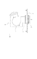
図6および図7は、前記投射ユニット20と前記押出型材71の構成を示した概略図であり、図7は装置側面から見た断面図である。
6 and 7 are schematic views showing configurations of the
装置D2において、前記補助部材72は該筐体内側に配置され、かつ前記押出型材71と比較して熱伝導率の低い材料、例えばABS等のプラスチック部材を使用する。
In the device D2, the
これにより、本実施例の形態によれば、前記第一の実施例における効果に加え、前記補助部材72は、前記押出型材71と比較して熱伝導率が低い為、放熱部材としての作用が小さくなり、前記熱気A2の熱が装置内部側へ放熱されることを低減でき、該装置内の温度が上昇してライトバルブ3等、該装置内の他部品の性能に及ぼす影響を低減できる。
Thereby, according to the form of the present embodiment, in addition to the effects in the first embodiment, the
尚、ここで、前記補助部材72と前記導風ダクト22を一体化しても良い。
Here, the
(実施例3)
以下図8乃至図9を参照して、本発明の第三の実施例について説明する。
(Example 3)
Hereinafter, a third embodiment of the present invention will be described with reference to FIGS.
尚、本実施例の構成は、第一、第二の実施例とほぼ同等であり、共通の構成要素については、第一、第二の実施例と同符号を付与し説明は省略する。 The configuration of the present embodiment is substantially the same as that of the first and second embodiments, and common constituent elements are given the same reference numerals as those of the first and second embodiments, and description thereof is omitted.
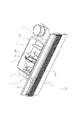
本実施例においては、装置D3の装置前面側には、その材質が熱伝導に優れた金属であるアルミニウム合金で、その断面形状がダクト形状811を含むように形成された押出型材81が、外壁部材として使用されている。 In the present embodiment, on the front side of the apparatus D3, an extrusion mold material 81 made of an aluminum alloy whose material is a metal having excellent heat conduction and having a cross-sectional shape including a duct shape 811 is provided on the outer wall. It is used as a member.
図8および図9は、記投射ユニット20と前記押出型材81の構成を示した概略図であり、図9は装置側面から見た断面図である。
8 and 9 are schematic views showing the configuration of the
装置D3において、前記押出型材81は、前記熱気A2が通過する前記押出型材81の筐体外部側、つまり前記押出型材81が外気と接する放熱面が、フィン形状となるように断面形状814を形成した。
In the apparatus D3, the extrusion mold material 81 has a
これにより、本実施例の形態によれば、前記第一または第二の実施例における効果に加え、前記フィン形状によって、外気と接する放熱面の表面積が増える為、前記押出型材81の放熱部材としての効果を向上させることが可能となる。 Thereby, according to the form of the present embodiment, in addition to the effects of the first or second embodiment, the fin shape increases the surface area of the heat radiation surface in contact with the outside air. It becomes possible to improve the effect.
(実施例4)
以下図10および図11を参照して、本発明の第四の実施例について説明する。
Example 4
Hereinafter, a fourth embodiment of the present invention will be described with reference to FIGS.
尚、本実施例の構成は、第一乃至第三の実施例とほぼ同等であり、共通の構成要素については、第一乃至第三の実施例と同符号を付与し説明は省略する。 The configuration of the present embodiment is substantially the same as that of the first to third embodiments, and common constituent elements are given the same reference numerals as those of the first to third embodiments, and description thereof is omitted.
本実施例においては、装置D4の装置前面側には、前述の第一の実施例と同じく、その材質が熱伝導に優れた金属であるアルミニウム合金で、その断面形状がダクト形状611を含むように形成された押出型材61が外壁部材として使用され、さらに前記押出型材61に放熱部材91を接合している。
In the present embodiment, on the front side of the device D4, as in the first embodiment, the material is an aluminum alloy which is a metal having excellent heat conduction, and the cross-sectional shape thereof includes a
図10および図11は、前記投射ユニット20と前記押出型材61、前記放熱部材91の構成を示した概略図であり、図11は装置側面から見た断面図である。
10 and 11 are schematic views showing configurations of the
D4においては、前述の第三の実施例に示したように、ダクト形状部を形成した押出型材にフィン形状を形成するのではなく、前記熱気A2が通過する前記押出型材61の筐体外部側に、放熱部材としてヒートシンク91を伝熱部材90を介して接合させて配置した。
In D4, as shown in the third embodiment, the outer shape of the
これにより、前記第三の実施例における効果に加え、ヒートシンク91の形状によって、放熱効果をコントロールすることが可能となる。 Thereby, in addition to the effect in the third embodiment, the heat radiation effect can be controlled by the shape of the heat sink 91.
また、放熱部材としてペルチェ素子等の冷却効果のある電子部品を採用すると、さらに放熱効果を向上させることが可能となる。 Further, if an electronic component having a cooling effect such as a Peltier element is employed as the heat radiating member, the heat radiating effect can be further improved.
(実施例5)
本実施例に係る投射型表示装置は、
光源が生じる熱を含む熱風を中空壁の中空部へ導くための導風路を有し、
中空壁において放熱された風を再び光源へ導くための導風路を有し、
両導風路と中空壁との間で連通された領域は筐体外部に対して閉鎖されている。それ以外は実施例1乃至4の何れかと同じである。
(Example 5)
The projection display device according to this embodiment is
An air guide path for guiding hot air containing heat generated by the light source to the hollow portion of the hollow wall;
Having a wind guide path for guiding the heat radiated in the hollow wall to the light source again,
The area | region connected between both the air ducts and the hollow wall is closed with respect to the housing | casing exterior. The rest is the same as any one of the first to fourth embodiments.
符号1201は光源であり、光源1201は容器1207に収容されている。光源1201は不図示の送風装置により冷却される。図中矢印は風の流れを示し。光源1201を通過した熱風は筐体1202である中空壁に送られる。
中空壁に送られた熱風は中空壁の筐体外側の壁から放熱される。放熱される領域を1202a、1202bに示した。本実施例では放熱される領域は筐体の一部である。もちろん全部でも良い。 The hot air sent to the hollow wall is radiated from the outer wall of the hollow wall. The areas to be dissipated are shown at 1202a and 1202b. In the present embodiment, the heat radiating area is a part of the casing. Of course everything is fine.
本実施例では光源が生じる熱を含む熱風を中空壁の中空部へ導くための導風路1203と、中空壁において放熱された風を再び光源へ導くための導風路1204とを有する。そのため中空壁の筐体1202と両導風路1203、1204と容器1207によって風は閉鎖された形の中を循環する。風は容器1207外且つ筐体1202内にも放出されず、また筐体1202外にも放出されない。符号1205、1206、1208は必要に応じて容器1207に設けられるライトバルブ、光学系(レンズやミラー)、フィルターである。
In this embodiment, there is an
本図の下の図は光源が生じる熱を含む熱風を中空壁の中空部へ導くための導風路1203付近を示す拡大模式図である。矢印は熱風の向きを示す。筐体1202は中空壁であり、中空壁は間仕切り1209により強度が保たれている。この間仕切り1209の向きを変えることにより熱風が筐体内を通過する方向を変えることも出来る。この間仕切りにも更に不図示の穴を設けても良い。
The lower part of the figure is an enlarged schematic view showing the vicinity of the
本実施形態に係る筐体として押出部材を用いることが好ましい。他の実施例と同様である。そしてより具体的にはアルミニウムを材料とするものが好ましい。 It is preferable to use an extrusion member as the housing according to the present embodiment. This is the same as the other embodiments. More specifically, a material made of aluminum is preferable.
本実施例に係る投射型表示装置は風の流路が閉鎖されているので静音が達成できる。 The projection type display apparatus according to the present embodiment can achieve quietness because the wind passage is closed.
1 投射ランプ
101 発光管
102 リフレクタ
2 冷却ファン
3 ライトバルブ
4 投射レンズ
5 全反射ミラー
6 スクリーン
20 投射ユニット
201 吸気口
21 導風ダクト
22 排気ダクト
50 筐体
60 筐体
61 外壁部材
611 断面形状
612 開口部
613 排気口
71 外壁部材
711 断面形状
72 補助部材
81 外壁部材
811 断面形状
814 フィン形状
90 伝熱部材
91 放熱部材
L1 投射光
L2 投射光
A1 冷却風
A2 熱気
1201 光源
1202 筐体
1203 導風路
1204 導風路
1205 ライトバルブ
1206 光学系
1207 容器
1208 フィルタ
1209 間仕切り
DESCRIPTION OF
Claims (1)
前記反射ミラーは前記投射光学系から投射された光をスクリーンへ折り返すためのミラーであり、
前記筺体の少なくとも一部が中空壁であり、前記中空壁は前記光源が生じる熱を放熱する放熱壁であり、
前記光源が生じる前記熱を含む熱風を前記中空壁の中空部へ導くための導風路を有し、
前記中空部へ導くための導風路は前記反射ミラーを有する空間を介さずに前記中空壁の中空部に前記熱風を導く導風路であり、
前記中空壁において放熱された風を再び前記光源へ導くための導風路を更に有し、 前記光源へ導くための導風路は前記反射ミラーを有する空間を介さずに前記光源へ前記風を導く導風路であることを特徴とする投射型表示装置。 In the projection type display device having a light source and a light valve and the projection optical system and the reflecting mirror and the screen in the casing,
The reflection mirror is a mirror for turning back the light projected from the projection optical system to the screen,
At least a part of the housing is a hollow wall, and the hollow wall is a heat radiating wall that radiates heat generated by the light source,
An air guide path for guiding hot air containing the heat generated by the light source to the hollow portion of the hollow wall;
The air guide path for guiding to the hollow part is an air guide path for guiding the hot air to the hollow part of the hollow wall without going through the space having the reflection mirror,
The air guide path for a further perforated for guiding the hollow wall again said light source radiating winds in, air guide path for guiding to the light source of the air to the light source without passing through the space with the reflective mirror A projection type display device characterized by being a guiding air guide .
Priority Applications (2)
| Application Number | Priority Date | Filing Date | Title |
|---|---|---|---|
| JP2005016791A JP4659466B2 (en) | 2005-01-25 | 2005-01-25 | Projection display |
| US11/275,673 US7762674B2 (en) | 2005-01-25 | 2006-01-24 | Projection-type display device |
Applications Claiming Priority (1)
| Application Number | Priority Date | Filing Date | Title |
|---|---|---|---|
| JP2005016791A JP4659466B2 (en) | 2005-01-25 | 2005-01-25 | Projection display |
Publications (3)
| Publication Number | Publication Date |
|---|---|
| JP2006208445A JP2006208445A (en) | 2006-08-10 |
| JP2006208445A5 JP2006208445A5 (en) | 2007-10-25 |
| JP4659466B2 true JP4659466B2 (en) | 2011-03-30 |
Family
ID=36696403
Family Applications (1)
| Application Number | Title | Priority Date | Filing Date |
|---|---|---|---|
| JP2005016791A Expired - Fee Related JP4659466B2 (en) | 2005-01-25 | 2005-01-25 | Projection display |
Country Status (2)
| Country | Link |
|---|---|
| US (1) | US7762674B2 (en) |
| JP (1) | JP4659466B2 (en) |
Families Citing this family (7)
| Publication number | Priority date | Publication date | Assignee | Title |
|---|---|---|---|---|
| CN101978319A (en) * | 2008-03-17 | 2011-02-16 | 三洋电机株式会社 | Projector |
| JP5294670B2 (en) * | 2008-03-27 | 2013-09-18 | 三洋電機株式会社 | Projection-type image display device and projection-type image display system using the same |
| US20110032489A1 (en) * | 2008-06-13 | 2011-02-10 | Takayuki Kimoto | Image display device |
| JP5132520B2 (en) * | 2008-10-29 | 2013-01-30 | 三菱電機株式会社 | Projection display |
| JP2010231066A (en) * | 2009-03-27 | 2010-10-14 | Sanyo Electric Co Ltd | Projection video display apparatus |
| JP5609213B2 (en) * | 2010-04-01 | 2014-10-22 | セイコーエプソン株式会社 | LCD projector |
| US20130010266A1 (en) * | 2011-07-05 | 2013-01-10 | Projectiondesign As | Compact Projector Head |
Citations (3)
| Publication number | Priority date | Publication date | Assignee | Title |
|---|---|---|---|---|
| JP2000305470A (en) * | 1999-04-23 | 2000-11-02 | Sony Corp | Display device |
| JP2000321989A (en) * | 1999-02-24 | 2000-11-24 | Canon Inc | Image display device |
| JP2003270720A (en) * | 2002-03-13 | 2003-09-25 | Seiko Epson Corp | Rear projector |
Family Cites Families (20)
| Publication number | Priority date | Publication date | Assignee | Title |
|---|---|---|---|---|
| WO1996030805A1 (en) * | 1995-03-30 | 1996-10-03 | Seiko Epson Corporation | Projection display |
| KR100252314B1 (en) * | 1997-05-09 | 2000-04-15 | 윤종용 | Projection television |
| JP3381566B2 (en) | 1997-07-18 | 2003-03-04 | ウシオ電機株式会社 | Light source unit |
| JP4103169B2 (en) * | 1998-04-06 | 2008-06-18 | ソニー株式会社 | Display device and cooling method thereof |
| JP3744223B2 (en) | 1998-09-08 | 2006-02-08 | ウシオ電機株式会社 | Light source device |
| US6595685B2 (en) * | 1998-10-13 | 2003-07-22 | National Research Laboratory Of Metrology | Method and apparatus for measuring thermophysical properties |
| JP2000284701A (en) * | 1999-03-31 | 2000-10-13 | Sony Corp | Display device |
| EP1102117A1 (en) * | 1999-05-28 | 2001-05-23 | Matsushita Electric Industrial Co., Ltd. | Image device |
| JP2001343708A (en) * | 2000-05-30 | 2001-12-14 | Canon Inc | Cooling mechanism for back projection type display apparatus |
| US6561655B2 (en) * | 2000-07-12 | 2003-05-13 | Minolta Co., Ltd. | Projector |
| JP3488687B2 (en) * | 2000-12-28 | 2004-01-19 | 株式会社東芝 | Detachable silencer and projection type projector with the same |
| US6966654B2 (en) * | 2001-05-28 | 2005-11-22 | Seiko Epson Corporation | Projector |
| US6497489B1 (en) * | 2001-08-29 | 2002-12-24 | Benq Corporation | Projector with guiding rib in vent |
| JP2003274314A (en) | 2002-03-13 | 2003-09-26 | Seiko Epson Corp | Rear projector and method for manufacturing the same |
| US7064956B2 (en) * | 2003-12-01 | 2006-06-20 | Hewlett-Packard Development Company, L.P. | Cooling system for a display projector |
| EP1701344A1 (en) * | 2003-12-03 | 2006-09-13 | Matsushita Electric Industrial Co., Ltd. | Optical disk device |
| US7628327B2 (en) * | 2004-03-26 | 2009-12-08 | Evans & Sutherland Computer Corporation | Shuttering system for scanning projectors |
| JP4155255B2 (en) * | 2004-09-21 | 2008-09-24 | ソニー株式会社 | Projector device |
| JP4428242B2 (en) * | 2005-01-28 | 2010-03-10 | セイコーエプソン株式会社 | Rear projector |
| JP4169017B2 (en) * | 2005-07-07 | 2008-10-22 | セイコーエプソン株式会社 | Image display device and control method of image display device |
-
2005
- 2005-01-25 JP JP2005016791A patent/JP4659466B2/en not_active Expired - Fee Related
-
2006
- 2006-01-24 US US11/275,673 patent/US7762674B2/en not_active Expired - Fee Related
Patent Citations (3)
| Publication number | Priority date | Publication date | Assignee | Title |
|---|---|---|---|---|
| JP2000321989A (en) * | 1999-02-24 | 2000-11-24 | Canon Inc | Image display device |
| JP2000305470A (en) * | 1999-04-23 | 2000-11-02 | Sony Corp | Display device |
| JP2003270720A (en) * | 2002-03-13 | 2003-09-25 | Seiko Epson Corp | Rear projector |
Also Published As
| Publication number | Publication date |
|---|---|
| US7762674B2 (en) | 2010-07-27 |
| JP2006208445A (en) | 2006-08-10 |
| US20060164603A1 (en) | 2006-07-27 |
Similar Documents
| Publication | Publication Date | Title |
|---|---|---|
| JP4659466B2 (en) | Projection display | |
| US7425793B2 (en) | Lamp cooling device and projection display apparatus | |
| US8678597B2 (en) | Projection type display device | |
| JP4172503B2 (en) | Cooling device and projector | |
| JP4480638B2 (en) | Through-flow forced air-cooled heat sink and projection display | |
| US6109767A (en) | Honeycomb light and heat trap for projector | |
| TWI235278B (en) | Light source device and projector | |
| JP2006106272A (en) | Display apparatus | |
| TWI310114B (en) | Projection type display unit | |
| WO2011111203A1 (en) | Projection display device | |
| JP6645667B2 (en) | Projection display device | |
| JP4240095B2 (en) | Sealed lamp device and projector | |
| JP3808422B2 (en) | COOLING STRUCTURE FOR PROJECTOR DEVICE AND PROJECTOR DEVICE | |
| WO2011033648A1 (en) | Display device | |
| US8172405B2 (en) | Lamp and optical projector | |
| JP2007114372A (en) | Cooling structure for heating source in housing and projector | |
| JP2006091697A (en) | Projector | |
| JP2006220708A (en) | Projection type display device | |
| JP2003157715A (en) | Light source lamp cooling structure | |
| JP2009251370A (en) | Projector | |
| TWI409575B (en) | Projector with single fan | |
| JP2006189486A (en) | Rear-projection apparatus | |
| KR100577198B1 (en) | apparatus for cooling lamp in projection system | |
| JP2024039756A (en) | Projector and hot water system | |
| JP4979237B2 (en) | Light source device |
Legal Events
| Date | Code | Title | Description |
|---|---|---|---|
| A521 | Request for written amendment filed |
Free format text: JAPANESE INTERMEDIATE CODE: A523 Effective date: 20070907 |
|
| A621 | Written request for application examination |
Free format text: JAPANESE INTERMEDIATE CODE: A621 Effective date: 20070907 |
|
| RD04 | Notification of resignation of power of attorney |
Free format text: JAPANESE INTERMEDIATE CODE: A7424 Effective date: 20100201 |
|
| RD01 | Notification of change of attorney |
Free format text: JAPANESE INTERMEDIATE CODE: A7421 Effective date: 20100630 |
|
| A131 | Notification of reasons for refusal |
Free format text: JAPANESE INTERMEDIATE CODE: A131 Effective date: 20100907 |
|
| A521 | Request for written amendment filed |
Free format text: JAPANESE INTERMEDIATE CODE: A523 Effective date: 20101108 |
|
| TRDD | Decision of grant or rejection written | ||
| A01 | Written decision to grant a patent or to grant a registration (utility model) |
Free format text: JAPANESE INTERMEDIATE CODE: A01 Effective date: 20101221 |
|
| A01 | Written decision to grant a patent or to grant a registration (utility model) |
Free format text: JAPANESE INTERMEDIATE CODE: A01 |
|
| A61 | First payment of annual fees (during grant procedure) |
Free format text: JAPANESE INTERMEDIATE CODE: A61 Effective date: 20101227 |
|
| FPAY | Renewal fee payment (event date is renewal date of database) |
Free format text: PAYMENT UNTIL: 20140107 Year of fee payment: 3 |
|
| R150 | Certificate of patent or registration of utility model |
Free format text: JAPANESE INTERMEDIATE CODE: R150 |
|
| LAPS | Cancellation because of no payment of annual fees |