EP2701475A1 - Housing for holding a flat screen - Google Patents
Housing for holding a flat screen Download PDFInfo
- Publication number
- EP2701475A1 EP2701475A1 EP12181373.7A EP12181373A EP2701475A1 EP 2701475 A1 EP2701475 A1 EP 2701475A1 EP 12181373 A EP12181373 A EP 12181373A EP 2701475 A1 EP2701475 A1 EP 2701475A1
- Authority
- EP
- European Patent Office
- Prior art keywords
- frame
- housing
- flat
- heat
- profile element
- Prior art date
- Legal status (The legal status is an assumption and is not a legal conclusion. Google has not performed a legal analysis and makes no representation as to the accuracy of the status listed.)
- Withdrawn
Links
Images


Classifications
-
- H—ELECTRICITY
- H05—ELECTRIC TECHNIQUES NOT OTHERWISE PROVIDED FOR
- H05K—PRINTED CIRCUITS; CASINGS OR CONSTRUCTIONAL DETAILS OF ELECTRIC APPARATUS; MANUFACTURE OF ASSEMBLAGES OF ELECTRICAL COMPONENTS
- H05K7/00—Constructional details common to different types of electric apparatus
- H05K7/20—Modifications to facilitate cooling, ventilating, or heating
- H05K7/2039—Modifications to facilitate cooling, ventilating, or heating characterised by the heat transfer by conduction from the heat generating element to a dissipating body
-
- G—PHYSICS
- G06—COMPUTING; CALCULATING OR COUNTING
- G06F—ELECTRIC DIGITAL DATA PROCESSING
- G06F1/00—Details not covered by groups G06F3/00 - G06F13/00 and G06F21/00
- G06F1/16—Constructional details or arrangements
- G06F1/1601—Constructional details related to the housing of computer displays, e.g. of CRT monitors, of flat displays
-
- G—PHYSICS
- G06—COMPUTING; CALCULATING OR COUNTING
- G06F—ELECTRIC DIGITAL DATA PROCESSING
- G06F1/00—Details not covered by groups G06F3/00 - G06F13/00 and G06F21/00
- G06F1/16—Constructional details or arrangements
- G06F1/20—Cooling means
-
- H—ELECTRICITY
- H05—ELECTRIC TECHNIQUES NOT OTHERWISE PROVIDED FOR
- H05K—PRINTED CIRCUITS; CASINGS OR CONSTRUCTIONAL DETAILS OF ELECTRIC APPARATUS; MANUFACTURE OF ASSEMBLAGES OF ELECTRICAL COMPONENTS
- H05K5/00—Casings, cabinets or drawers for electric apparatus
- H05K5/02—Details
-
- H—ELECTRICITY
- H05—ELECTRIC TECHNIQUES NOT OTHERWISE PROVIDED FOR
- H05K—PRINTED CIRCUITS; CASINGS OR CONSTRUCTIONAL DETAILS OF ELECTRIC APPARATUS; MANUFACTURE OF ASSEMBLAGES OF ELECTRICAL COMPONENTS
- H05K7/00—Constructional details common to different types of electric apparatus
- H05K7/18—Construction of rack or frame
-
- H—ELECTRICITY
- H05—ELECTRIC TECHNIQUES NOT OTHERWISE PROVIDED FOR
- H05K—PRINTED CIRCUITS; CASINGS OR CONSTRUCTIONAL DETAILS OF ELECTRIC APPARATUS; MANUFACTURE OF ASSEMBLAGES OF ELECTRICAL COMPONENTS
- H05K7/00—Constructional details common to different types of electric apparatus
- H05K7/20—Modifications to facilitate cooling, ventilating, or heating
- H05K7/20954—Modifications to facilitate cooling, ventilating, or heating for display panels
- H05K7/20963—Heat transfer by conduction from internal heat source to heat radiating structure
-
- Y—GENERAL TAGGING OF NEW TECHNOLOGICAL DEVELOPMENTS; GENERAL TAGGING OF CROSS-SECTIONAL TECHNOLOGIES SPANNING OVER SEVERAL SECTIONS OF THE IPC; TECHNICAL SUBJECTS COVERED BY FORMER USPC CROSS-REFERENCE ART COLLECTIONS [XRACs] AND DIGESTS
- Y10—TECHNICAL SUBJECTS COVERED BY FORMER USPC
- Y10T—TECHNICAL SUBJECTS COVERED BY FORMER US CLASSIFICATION
- Y10T29/00—Metal working
- Y10T29/49—Method of mechanical manufacture
- Y10T29/49826—Assembling or joining
Definitions
- the present invention relates to a housing for receiving a flat screen, a method for producing such a housing and a device having such a housing and a flat screen recorded therein.
- Such housings are commonly used in the installation of flat panel displays in public places and especially in vehicles as installation and protection device for the flat screen.
- flat panel displays are often installed to provide information to a relevant public or to entertain people.
- This can be LCD, TFT, FED or LED screens, but also plasma screens or other types of flat screens are used.
- LCD, TFT, FED or LED screens are usually provided per vehicle to display the passengers, for example, current timetables, safety information or news from world events.
- To attach the flat screens and protect against external mechanical damage they are usually housed in a housing. The housing with the flat screen received therein is then fastened to or in a building or vehicle, etc., at a suitable location which is easily visible to the corresponding public.
- a housing of the type described above is for example in the US 7,619,881 described.
- a housing is proposed, as indicated in claim 1.
- a method for producing such a housing is specified in claim 12.
- a further object of the present invention is to provide a housing for receiving a flat screen, in which the dissipation of the heat generated in the flat screen to the outside at any time to a sufficient extent is guaranteed.
- a housing is proposed, as indicated in claim 9.
- a device which has a housing and a flat screen recorded therein.
- Advantageous embodiments of the invention are specified in the dependent claims.
- the present invention thus provides a housing for receiving a flat screen, with a frame which limits a housing interior for receiving the flat screen.
- the frame is made of a particular extruded flat profile element having a plurality of predetermined bending points, which serve to define the corner regions of the frame.
- the frame of the housing surrounds the interior of the housing laterally, that is to say on that side of the flat screen accommodated in the housing, which extends perpendicular to the display surface of the screen.
- the frame is made of a flat profile element with correspondingly provided predetermined bending points.
- the frame and thus the housing are extremely simple and inexpensive to produce and especially in the production very easy to adapt to any types and sizes of flat screens.
- the generally one-piece flat profile element is preferably made of a metal, and particularly preferably made of aluminum.
- the weight of the housing is thus about 40% lower compared to a corresponding housing made of cast aluminum.
- the thermal conductivity of aluminum profiles and in particular of extruded aluminum profiles is considerably better than that of cast aluminum.
- the flat screen can in particular be an LCD, TFT, FED or LED screen or even a plasma screen.
- the flat screen can be referred to in particular as a display panel, a display or a monitor.
- the flat screen compared to its other dimensions a relatively much smaller thickness, measured in a direction perpendicular to the display surface direction.
- a flat profile element is selected whose width is approximately equal to or slightly larger than the thickness of the flat screen to be accommodated in the housing.
- the thickness of the flat screen here and in the following means in each case that dimension which extends perpendicularly to the display surface of the screen.
- the flat profile element In the production of the frame is usually adjusted in a first step, the flat profile element with respect to its length to the peripheral length of the flat panel, so that later preferably results in a frame which is designed such that it the flat screen laterally to a large extent, in particular preferably substantially completely surrounds.
- the length of the flat profile element thus preferably corresponds approximately to the circumferential length of the flat screen.
- a plurality of, in particular exactly three or exactly four, predetermined bending points are then generally provided along the longitudinal direction of the flat profile element in order to determine the positions of the corner regions of the later frame.
- the distances of the various predetermined bending points to each other along the longitudinal direction of the flat profile element advantageously correspond approximately to the side lengths of the flat screen.
- the flat profile element can then in the areas of the predetermined bending points preferably bent by more than 80 ° and less than 100 °, in particular by approximately 90 °, so that an advantageous rectangular, suitable for receiving the flat screen frame is formed.
- further steps may be taken in the manufacture of the frame.
- bores, recesses and grooves can be provided on the flat profile element.
- Location and direction information such as above, below, front, rear, above, below, inward and outward refer in the following each in a proper manner, for example, on or in a vehicle or on or in a building mounted housing with a flat screen received therein, in which the display surface faces forward and extends approximately parallel to the direction of gravity, so that an upright observer has an optimal view of the flat-panel display arranged at eye level.
- the predetermined bending points are each defined by a dilution of material at the appropriate location.
- the material dilution can be produced in any desired manner, such as, in particular, by means of a machining process, for example milling, and extends advantageously, but not necessarily, essentially over the entire width of the flat profile element and in particular substantially into a relative one to the longitudinal direction perpendicular direction.
- the predetermined bending points are each defined by a material dilution
- the bending of the flat profile element can be made into a frame in a particularly simple and precise manner, with a relatively small amount of force.
- the material dilutions are advantageously provided in the form of depressions on that side of the flat profile element, which forms the side facing the housing interior in the finished frame produced.
- the flat profile element is in each case preferably diluted by at least half, more preferably by at least two thirds, and most preferably by at least three quarters of the material thickness.
- the material dilutions are preferably each formed by a groove, which is a can have any shape.
- the groove may for example be designed in particular V-shaped or U-shaped.
- the groove is configured as a hybrid of a V-shaped and a U-shaped groove.
- a groove according to such a hybrid form is bounded by two planar surfaces and a curved surface arranged therebetween.
- Such a configured groove forms a clearly defined predetermined bending point, which allows a simple and precise bending of the flat profile element at the appropriate location. The bending then takes place in particular in the region of the curved surface of the groove.
- the radius of the arcuate surface is at least one twelfth, more preferably at least one tenth, and most preferably at least one eighth of the thickness of the flat profile element.
- the two flat surfaces of the groove form an angle of more than 60 ° and less than 120 °, in particular more than 80 ° and less than 100 °. Most advantageously, however, they include an angle of approximately 90 °.
- the two planar surfaces of the groove then preferably extend substantially parallel to one another and, in particular, are preferably adjacent to one another.
- the frame preferably forms a substantially closed rectangle whose side lengths are advantageously approximately in a ratio of 4: 3, 15: 9, 16: 9 or 16:10 to each other.
- the frame may in particular have a connection point, in which the two ends of the flat profile element are interconnected.
- the frame is thus designed such that it encloses a flat screen received in the housing substantially completely laterally in the circumferential direction.
- a connection plate can be provided, by means of which the two ends of the flat profile element are connected to one another.
- This connection plate is preferably fastened on the outside of the frame.
- the two end surfaces of the flat profile element in the longitudinal direction can abut each other, but need not.
- connection point is advantageously arranged in the vicinity of one of the corner regions of the frame.
- the connection point but in particular also form one of the corner regions of the frame.
- the frame has a recess which serves to receive an electronic component, and which is arranged in particular in the region of the connection point. Preferably, this recess is laterally completely surrounded by the material of the frame.
- the two ends of the flat profile element bound the recess together.
- both ends of the flat profile element advantageously each have an opening which is open towards the outside in the longitudinal direction of the flat profile element.
- the electronic component may in particular be a printed circuit board which may have display elements such as LEDs and sensors which serve, for example, to display the operating state of the flat screen and to measure the brightness conditions in the surroundings.
- the frame may have correspondingly arranged bores which extend from an inner surface bounding the recess to a surface of the frame facing towards the front.
- notches may also be provided on the frame in the region of the recess, which notches serve to hold the printed circuit board in the recess.
- laterally protruding projections of the printed circuit board which in particular each have the shape of a pin, can then be inserted into the indentations in order to hold the printed circuit board in the recess.
- the indentations may be designed to be open, in particular to the recess and preferably also to the side on which a connecting plate is attached to the frame. By attaching the connecting plate to the frame, the indentations are then preferably closed to the corresponding side, so that an inserted with their lateral projections in the notches printed circuit board is held in the housing.
- the housing has a rear wall, which serves for closing the laterally limited by the frame housing interior on the back.
- at least one connecting tab is attached to the rear wall, which is for fastening the Rear wall on the frame is used.
- the one or more connecting straps are advantageously attached to the rear wall substantially along the entire circumference such that they protrude substantially perpendicularly therefrom.
- the rear wall, together with the connecting straps attached thereto is made in one piece from a metal sheet, in particular an aluminum sheet.
- the connection of the connecting straps to the frame can in particular be effected by means of screws, which advantageously have a certain clearance before being tightened in corresponding connection bores of the frame provided for this purpose.
- the disassembly and reassembly of the housing, for example, for repair can then be done in a simple manner, and it can be ensured that the rear wall at any time rests against the back of the housed in the housing flat panel.
- the present invention also provides a housing which can be designed as described above, serves to receive a flat screen and has a frame which delimits a housing interior for receiving the flat screen, and at least one heat-dissipating element, which on the inside of the frame is mounted, and which for transferring heat, which arises in the housing interior, serves on the frame.
- the frame has on its side facing the housing interior side an inner groove into which the heat dissipating element is inserted.
- the flat screen accommodated therein can be clamped in particular between the heat-dissipating element and, for example, a rear wall of the housing. In this way it can be ensured that the flat screen is in contact with the heat-dissipating element at all times, whereby the dissipation of the heat arising in the flat screen is ensured.
- the heat-dissipating element can be any element projecting from the frame into the interior of the housing, which element is preferably made of a metal, in particular aluminum.
- the heat-dissipating element is preferably designed as a strip which is inserted along one of its longitudinal sides into the inner groove.
- the heat dissipating member may be press-fitted into the inner groove and / or fixed in the inner groove by means of an adhesive or other fastener such as screws.
- the inner groove and in particular also the heat-dissipating element extend along the entire circumference of the housing interior bounded by the frame.
- the heat-dissipating element may also extend only over a part of the circumference and in particular may be provided only along an upper longitudinal side of the frame.
- the housing also has a front window, which may be glued to the heat-dissipating element and in particular to its forwardly facing side.
- the heat dissipating element is then advantageously arranged between the flat screen and the front screen, which is generally used to protect the display surface of the flat screen.
- the housing may also have a front panel, which is preferably screwed to the frame and is advantageously configured such that it completely covers the heat-dissipating element towards the front of the viewer.
- a housing which is formed according to the above statements, is overall very simple and inexpensive to produce, and the dissipation of heat generated in the housing can be ensured at any time in a simple manner.
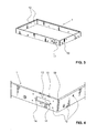
- FIG. 1 and 2 is a housing according to a first embodiment of the invention, shown for receiving a flat screen.
- the housing has a housing interior 8, which is suitable for receiving a flat screen, and which is bounded laterally by a frame 1, forward through a windscreen 4 and to the rear by a rear wall 5.
- a front panel 2 is attached to the frame 1, which has a large, rectangular opening through which the display area or the display of the recorded in the housing screen is visible.
- a plurality of connecting straps 21 are mounted on the back of the front panel 2, which abut in the assembled state of the housing on the outside of the frame 1.
- the connecting straps 21 each have bores which correspond with connecting bores 12 of the frame 1 in order to allow screw connections between the front panel 2 and the frame 1.
- a plurality of bores 22 are provided, which are used for fastening the front panel 2 for example, on or in a vehicle or building.
- the front panel 2 also has recesses 23, which allow the user to view an LED display arranged behind it.
- the LED display whose arrangement is explained in more detail below in the housing, for example, serve to display the operating status or the concern of a mains voltage on the flat screen. Behind the recesses 23 but also sensors can be arranged, which can serve for example for measuring the ambient brightness.
- a control circuit module 6 is mounted in the present embodiment, which has a separate housing with respect to the housing for the flat screen, which, for example, for receiving a Control circuit for controlling the flat screen is used.
- the rear wall 5 and the control circuit module 6 each have at least one corresponding recess, which serves to pass through cable strands or control lines.
- the control circuit module 6 has on its outer side terminals 61 to supply the control circuit module 6, for example, with a mains voltage or to connect to a data communication cable.
- the electronic components for controlling the flat screen are housed in a separate housing of the control circuit module 6, the air spaces, as far as the heat development of the flat panel and the electronic control, are substantially completely separated from each other, so that the respective heat generated independently can be dissipated.
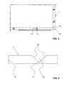
- the design of the frame 1 is particularly in the FIGS. 3 to 6 good to see.
- the frame 1 is made of a simple flat profile element, which in turn can be made by simply extruding a metal, such as aluminum in particular.
- the length of the flat profile element used is chosen such that it is slightly longer than the lateral circumference of the enclosed flat screen.
- a plurality of predetermined bending points are milled into the flat profile element, which serve to fix the corner regions 19 of the frame 1.
- the predetermined bending points are each formed as grooves 15, which extend substantially perpendicular to the longitudinal direction of the flat profile element over its entire width.
- grooves 15 are provided.
- the depth of the grooves 15 is in each case about two thirds to about three quarters of the thickness of the flat profile element.
- the grooves 15 are milled into the flat profile element such that they, as shown in FIG. 6 can be seen, of two flat surfaces 16 and an intermediate, curved surface 17 are limited.
- the flat surfaces 16 enclose an angle of approximately 90 °.
- the flat profile element can then with little effort and in a precise manner in the in FIG. 3 shown, rectangular shape of the frame 1 are brought with well-defined corners 19.
- the flat surfaces 16 of the grooves 15 each extend parallel to each other, and substantially parallel to the bisector predetermined by the respective corner region 19 (see FIG. 5 ).
- connecting holes 12 are formed, which in particular allow the production of screw with the front panel 2, the rear wall 5 and the connection plate 3 explained below.
- the connecting bores 12 may each be provided with an internal thread.
- the connections can also be made by means of screw and nut.
- the compounds of the mentioned components can also be designed, for example, as adhesive or riveted joints.
- the flat profile element used for the production of the frame 1 has two ends in the longitudinal direction, which in the present embodiment after the formation of the frame 1 are arranged directly adjacent to each other or even abut each other to form a joint 13.
- This junction 13 is, as it is in the Figures 5 . 7 and 8 is shown connected by means of a connecting plate 3.
- This connection plate 3 is screwed to the outside of the frame 1 such that it is fixedly attached to both ends of the flat profile element.
- the connection plate 3 and the frame 1 in the region of the connection point 13 each have corresponding holes 31 and 12, respectively.
- the frame 1 has a recess 11. This is formed in the space provided for the preparation of the frame 1 flat profile element in the region of the two ends as a respective outwardly open recess. Due to the recess 11, the two ends of the flat profile element therefore each have a substantially U-shaped configuration. After joining the two ends of the flat profile element at the connection point 13, the recess 11 describes a rectangular shape, which is completely covered by the connection plate 3 downwards.
- the recess 11 serves to receive an electronic component, which in particular can be designed as a printed circuit board or printed circuit board.
- the recess 11 serves to receive a populated with LEDs and sensors printed circuit board.
- the LEDs and sensors are used to display the operating state of the flat screen recorded in the housing or to measure the brightness conditions in the environment.
- the frame 1 has viewing bores 10, which extend from an inner surface of the recess 11 to the forwardly directed surface of the frame 1, and which thus extend substantially parallel to the direction in which a viewer usually on the display surface a recorded in the housing screen looks.
- the sight holes 10 are each arranged such that they are aligned with mounted on the frame 1 front panel 2 with the recesses 23 of the front panel 2. A visual connection from the outside to the LEDs or sensors of the printed circuit board is thus ensured by the sight bores 10 and the recesses 23 therethrough.
- two opposite notches 14 are present at the edge of the recess 11.
- the notches 14 are adapted to receive correspondingly shaped pins which are attached to the printed circuit board and project laterally from this.
- the notches 14 are each formed to the recess 11 and the underside of the frame 1 towards open.
- a printed circuit board can be used in a simple manner from below into the recess 11 and with the laterally projecting pins in the notches 14.
- the connecting plate 3 is attached to the frame 1, the notches 14 are closed at the bottom, so that the printed circuit board is held with their laterally projecting pins in the notches 14.
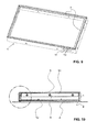
- a circumferential inner groove 18 is formed on the inside of the frame 1.
- This inner groove 18 is disposed in a front portion of the frame 1.
- the inner groove 18 is already milled into the not yet formed into a frame 1 flat profile element.
- the inner groove 18 then extends parallel to the longitudinal direction of the flat profile element and preferably substantially over the entire length of the flat profile element.
- the inner groove 18 but also after bending of the flat profile element to a frame. 1 are milled in the inside.
- the inner groove 18 is used for insertion of heat-dissipating strips 7, which in the Figures 9 and 11 are clearly recognizable.
- a heat dissipating bar 7 is inserted into the inner groove 18, in particular pressed.
- the heat-dissipating strips 7 are made of a good heat-conducting material, in particular a metal sheet.
- the housing is designed such that a flat screen recorded in the housing rests with its forwardly directed edge region directly substantially circumferentially on the respective rearwardly directed side of the heat-dissipating strips 7. In this way, heat, which arises in particular due to the backlighting in the flat screen, be transmitted by means of heat conduction via the heat dissipating strips 7 on the frame 1.
- the rear wall 5 which may be made in particular of a simple aluminum sheet, has vertically protruding connecting straps 51, which are arranged substantially circumferentially around the rear wall 5 around (see FIGS. 10 to 12 ).
- the connecting straps 51 on the one hand serve for fastening the rear wall 5 on the inside of the frame 1 by means of screw connections.
- the connecting straps 51 also serve to produce a thermally conductive connection between the frame 1 and the rear wall 5. Thermal energy arising in the flat screen, which is transmitted from the edge strips 7 to the frame 1, can thereby be conducted on the rear wall 5 via the connecting straps 51 become.
- heat radiating elements such as rib-like structures, may be attached, which radiate the heat energy into the environment. In the present embodiment, however, no such heat radiating elements are provided, since the rear wall 5 already forms a sufficiently large area in order to radiate the heat energy arising in the flat screen outwards.
- the rear wall 5 is preferably screwed to the frame 1 in such a way that a flat screen accommodated in the interior of the housing is held firmly between the heat-dissipating strips 7 and the rear wall 5 and, in particular, is clamped therebetween. A optimal heat transfer from the flat screen to the housing can be ensured.
- screw-nut connections are provided for the connections between the connecting plates 51 and the frame 1, and also the corresponding connection holes 12 are formed such that the screw before tightening the respective screw a certain play in the connecting hole 12, a tight concerns of the rear wall 5 are ensured at the rear of the flat screen even with manufacturing tolerances.
- the windshield 4 is preferably placed on the forwardly facing surfaces of the heat-dissipating strips 7 and in particular adhered thereto.
- FIGS. 10 to 12 an alternative, less preferred embodiment is shown with respect to the arrangement of the windshield 4, in which the windshield 4 is adhered to the rearwardly facing surfaces of the heat dissipating strips 7 instead of to the forwardly facing surfaces.
- the windscreen 4 is thus arranged between the heat-dissipating strips 7 and the flat screen in this alternative embodiment.
- an arrangement in which the heat dissipating strips 7, unlike in the figures, between the windscreen 4 and the flat screen are preferred.
- the invention described herein is not limited to the mentioned embodiment, and a variety of modifications are possible.
- the production of the frame 1 from a flat profile element with a plurality of predetermined bending points on the one hand, and the provision of an inner groove 18 on the frame 1 for insertion of the heat-dissipating elements 7 on the other hand represent two independent inventions.
- a housing with a frame to provide which is made of a flat profile element with a plurality of predetermined bending points, but has no inner groove for heat-dissipating elements. The heat can then be dissipated in another manner known to those skilled in the art.
- a housing with a frame which has on its inner side an inner groove for heat dissipating elements, but is not made of a flat profile element, but for example made of cast aluminum. If heat-dissipating strips are present, they do not necessarily have to be provided peripherally.
- a housing with a frame is conceivable, which, for example, only along its upper side has a heat dissipating bar.
- the heat-dissipating elements do not even have to be designed as strips, but can be configured as any protrusions projecting from the inside of the frame into the housing interior 8, which projections are suitable for contact with the flat-screen.
- the frame does not necessarily have to be designed in such a way that it is completely closed in the circumferential direction.
- the two ends of the flat profile element can also be arranged at a distance from each other in the finished bent frame, and it is not absolutely necessary that they are connected to one another via a connecting plate.
- the front panel 2, the frame 1, the connecting plate 3, the heat-dissipating strips 7, the rear wall 5 and the control circuit module 6 may be interconnected in any manner known to those skilled in the art.
- screw, rivet or adhesive connections are conceivable.
- the predetermined bending points need not necessarily be formed as milled grooves, but can be formed by any material dilutions at the appropriate points, for example, by means of rollers, press, etc., be formed. Also, predetermined bending points based on perforations at the corresponding points of the flat profile element are possible.
- 5 further heat dissipating elements may be attached to the inner surface of the rear wall, which are provided for abutment with the rear wall of the flat panel.
- These heat-dissipating elements can in particular be designed in such a way that, due to their shape, they are at least slightly elastically compressible in a direction perpendicular to the inner surface of the rear wall. The heat-dissipating elements are then clamped like a spring between the two surfaces of the rear wall and the flat screen.
- Such a shape of these additional heat-dissipating elements can be achieved, for example, by having an overall Z-shaped or S-shaped configuration. The compressibility ensures that these heat-dissipating elements, even taking into account manufacturing tolerances at any time abut the flat screen recorded in the housing and thereby derive the resulting heat to the rear wall and thus to the outside.
Landscapes
- Engineering & Computer Science (AREA)
- Theoretical Computer Science (AREA)
- Physics & Mathematics (AREA)
- General Engineering & Computer Science (AREA)
- Microelectronics & Electronic Packaging (AREA)
- Human Computer Interaction (AREA)
- General Physics & Mathematics (AREA)
- Thermal Sciences (AREA)
- Computer Hardware Design (AREA)
- Devices For Indicating Variable Information By Combining Individual Elements (AREA)
Abstract
Description
Die vorliegende Erfindung betrifft ein Gehäuse zur Aufnahme eines Flachbildschirms, ein Verfahren zur Herstellung eines derartigen Gehäuses sowie eine Vorrichtung, welche ein solches Gehäuse sowie einen darin aufgenommenen Flachbildschirm aufweist. Derartige Gehäuse werden üblicherweise bei der Installation von Flachbildschirmen im öffentlichen Raum und insbesondere in Fahrzeugen als Installations- und Schutzvorrichtung für den Flachbildschirm verwendet.The present invention relates to a housing for receiving a flat screen, a method for producing such a housing and a device having such a housing and a flat screen recorded therein. Such housings are commonly used in the installation of flat panel displays in public places and especially in vehicles as installation and protection device for the flat screen.
Im öffentlichen Raum und insbesondere in Fahrzeugen des öffentlichen Verkehrs werden oft Flachbildschirme montiert, um einem entsprechenden Publikum Informationen zukommen zu lassen, oder um die Leute zu unterhalten. Dazu können LCD-, TFT-, FED- oder LED-Bildschirme, aber auch Plasmabildschirme oder andere Typen von Flachbildschirmen eingesetzt werden. Insbesondere in Bussen, Zügen und Flugzeugen sind heutzutage pro Fahrzeug üblicherweise meist mehrere Flachbildschirme vorgesehen, um den Passagieren beispielsweise aktuelle Fahrpläne, Sicherheitshinweise oder Neuigkeiten aus dem Weltgeschehen anzuzeigen. Um die Flachbildschirme zu befestigen und vor äusserer mechanischer Beschädigung zu schützen, sind diese üblicherweise in einem Gehäuse aufgenommen. Das Gehäuse mit dem darin aufgenommenen Flachbildschirm wird dann an einer geeigneten, für das entsprechende Publikum gut sichtbaren Stelle an oder in einem Gebäude bzw. einem Fahrzeug etc. befestigt.In public places, and especially in public transport vehicles, flat panel displays are often installed to provide information to a relevant public or to entertain people. This can be LCD, TFT, FED or LED screens, but also plasma screens or other types of flat screens are used. In particular, in buses, trains and aircraft nowadays usually more flat screens are usually provided per vehicle to display the passengers, for example, current timetables, safety information or news from world events. To attach the flat screens and protect against external mechanical damage, they are usually housed in a housing. The housing with the flat screen received therein is then fastened to or in a building or vehicle, etc., at a suitable location which is easily visible to the corresponding public.
Ein Gehäuse der eingangs beschriebenen Gattung ist beispielsweise in der
Da derartige Gehäuse insbesondere Schutz gegen äussere, vor allem mechanische Einflüsse bieten sollen, sollten sie eine robuste Bauweise aufweisen und derart ausgestaltet sein, dass die darin aufgenommenen Flachbildschirme zu möglichst allen Seiten hin geschützt sind. Im Stand der Technik werden oft Gehäuse verwendet, die aus Guss-Aluminium oder aus gefrästem Aluminium hergestellt sind. Nachteilig sind dabei jedoch das beträchtliche Gewicht sowie die aufwändige und kostspielige Herstellung derartiger gegossener oder gefräster Gehäuse.Since such housing should provide particular protection against external, especially mechanical influences, they should have a robust construction and be designed such that the flat screens housed therein are protected to all sides possible. The prior art often uses housings made of cast aluminum or milled aluminum. The disadvantage here, however, the considerable weight and the complex and costly production of such cast or milled housing.
Da elektronische Geräte im Allgemeinen und Flachbildschirme im Speziellen, hauptsächlich aufgrund von ihrer Hinterleuchtung, während ihrem Betrieb Wärme produzieren, stellt die Wärmeabführung nach aussen hin ein weiteres wichtiges Anforderungskriterium für derartige Gehäuse zur Aufnahme eines Flachbildschirms dar. In den Dokumenten
In vielen Fällen ist die Wärmeabfuhr jedoch trotz allen dafür vorgesehenen Vorkehrungen ungenügend, und es entsteht ein Wärmestau im Inneren des Gehäuses.In many cases, however, the heat dissipation is in spite of all the provisions provided for insufficient, and there is a heat accumulation inside the housing.
Die meisten Gehäuse des Standes der Technik weisen eine verhältnismässig aufwändige und entsprechend kostspielige Bauweise auf. Die Gehäuse sind meist für bestimmte Typen und Grössen von Flachbildschirmen ausgelegt, und der Herstellungsprozess dieser Gehäuse kann nur mit einem verhältnismässigen beträchtlichen Aufwand an anders ausgestaltete Flachbildschirme angepasst werden. Ausserdem ist bei Gehäusen des Standes der Technik der direkte Kontakt der wärmeabführenden Strukturen mit dem Flachbildschirm aufgrund von fertigungstechnischen Toleranzen nicht immer gewährleistet. Es besteht dadurch das Problem, dass die insbesondere im Bereich der Hinterleuchtung im Flachbildschirm entstehende Wärme nicht ausreichend nach aussen hin abgeführt werden kann. Im Extremfall kann dies zu einer irreversiblen Beschädigung des Flachbildschirms führen.Most cases of the prior art have a relatively complex and correspondingly expensive construction. The enclosures are typically designed for specific types and sizes of flat panel displays, and the manufacturing process of these enclosures can only be adapted with a relatively large amount of expense to differently designed flat panel displays. Moreover, in housings of the prior art, the direct contact of the heat dissipating structures with the flat screen due to manufacturing tolerances is not always guaranteed. There is thus the problem that the resulting in particular in the field of backlighting in the flat panel heat is not sufficient outward can be dissipated. In extreme cases, this can lead to irreversible damage to the flat screen.
Es ist also eine Aufgabe der vorliegenden Erfindung, ein Gehäuse zur Aufnahme eines Flachbildschirms anzugeben, dessen Herstellung nicht nur verhältnismässig einfach und kostengünstig ist, sondern auch einfach an beliebige Typen und Grössen von Flachbildschirmen anpassbar ist. Zur Lösung dieser Aufgabe wird ein Gehäuse vorgeschlagen, wie es in Anspruch 1 angegeben ist. Ausserdem wird in Anspruch 12 ein Verfahren zur Herstellung eines derartigen Gehäuses angegeben.It is therefore an object of the present invention to provide a housing for receiving a flat screen, the production of which is not only relatively simple and inexpensive, but also easily adaptable to any types and sizes of flat screens. To solve this problem, a housing is proposed, as indicated in
Eine weitere Aufgabe der vorliegenden Erfindung besteht darin, ein Gehäuse zur Aufnahme eines Flachbildschirms bereitzustellen, bei dem das Abführen der im Flachbildschirm entstehenden Wärme nach aussen hin jederzeit in ausreichendem Masse gewährleistet ist. Zur Lösung dieser Aufgabe wird ein Gehäuse vorgeschlagen, wie es in Anspruch 9 angegeben ist.A further object of the present invention is to provide a housing for receiving a flat screen, in which the dissipation of the heat generated in the flat screen to the outside at any time to a sufficient extent is guaranteed. To solve this problem, a housing is proposed, as indicated in claim 9.
In Anspruch 15 wird zudem eine Vorrichtung angegeben, welche ein Gehäuse sowie einen darin aufgenommenen Flachbildschirm aufweist. Vorteilhafte Ausgestaltungen der Erfindung sind in den abhängigen Ansprüchen angegeben.In
Die vorliegende Erfindung stellt also ein Gehäuse zur Aufnahme eines Flachbildschirms zur Verfügung, mit einem Rahmen, welcher einen Gehäuseinnenraum zur Aufnahme des Flachbildschirms begrenzt. Der Rahmen ist aus einem insbesondere stranggepressten Flachprofilelement hergestellt, welches mehrere Sollbiegestellen aufweist, die zur Festlegung der Eckbereiche des Rahmens dienen.The present invention thus provides a housing for receiving a flat screen, with a frame which limits a housing interior for receiving the flat screen. The frame is made of a particular extruded flat profile element having a plurality of predetermined bending points, which serve to define the corner regions of the frame.
In der Regel umschliesst der Rahmen des Gehäuses den Gehäuseinnenraum seitlich, das heisst zu derjenigen Seite des im Gehäuse aufgenommenen Flachbildschirms hin, welche sich senkrecht zur Anzeigefläche des Bildschirms erstreckt. Dadurch, dass der Rahmen aus einem Flachprofilelement mit entsprechend vorgesehenen Sollbiegestellen hergestellt ist, sind der Rahmen und somit das Gehäuse äusserst einfach und kostengünstig herstellbar und insbesondere bei der Herstellung sehr einfach an beliebige Typen und Grössen von Flachbildschirmen anpassbar. Das in der Regel einstückige Flachprofilelement ist bevorzugt aus einem Metall, und insbesondere bevorzugt aus Aluminium, hergestellt. Das Gewicht des Gehäuses ist dadurch um ca. 40 % geringer im Vergleich zu einem entsprechenden aus Guss-Aluminium hergestellten Gehäuse. Ausserdem ist die Wärmeleitfähigkeit von Aluminiumprofilen und insbesondere von stranggepressten Aluminiumprofilen erheblich besser wie von Guss-Aluminium.As a rule, the frame of the housing surrounds the interior of the housing laterally, that is to say on that side of the flat screen accommodated in the housing, which extends perpendicular to the display surface of the screen. Characterized in that the frame is made of a flat profile element with correspondingly provided predetermined bending points, The frame and thus the housing are extremely simple and inexpensive to produce and especially in the production very easy to adapt to any types and sizes of flat screens. The generally one-piece flat profile element is preferably made of a metal, and particularly preferably made of aluminum. The weight of the housing is thus about 40% lower compared to a corresponding housing made of cast aluminum. In addition, the thermal conductivity of aluminum profiles and in particular of extruded aluminum profiles is considerably better than that of cast aluminum.
Beim Flachbildschirm kann es sich insbesondere um einen LCD-, TFT-, FED- oder LED-Bildschirm oder auch um einen Plasmabildschirm handeln. Je nach Ausgestaltung kann der Flachbildschirm insbesondere auch als ein Anzeigepanel, ein Display oder ein Monitor bezeichnet werden. Grundsätzlich weist der Flachbildschirm im Vergleich zu seinen übrigen Abmessungen eine verhältnismässig wesentlich geringere Dicke auf, gemessen in eine senkrecht zur Anzeigefläche stehende Richtung.The flat screen can in particular be an LCD, TFT, FED or LED screen or even a plasma screen. Depending on the configuration, the flat screen can be referred to in particular as a display panel, a display or a monitor. Basically, the flat screen compared to its other dimensions a relatively much smaller thickness, measured in a direction perpendicular to the display surface direction.
Üblicherweise wird ein Flachprofilelement gewählt, dessen Breite ungefähr gleich gross oder geringfügig grösser als die Dicke des im Gehäuse aufzunehmenden Flachbildschirms ist. Unter der Dicke des Flachbildschirms ist hierbei und im Folgenden jeweils diejenige Dimension gemeint, welche senkrecht zur Anzeigefläche des Bildschirms erstreckt.Usually, a flat profile element is selected whose width is approximately equal to or slightly larger than the thickness of the flat screen to be accommodated in the housing. The thickness of the flat screen here and in the following means in each case that dimension which extends perpendicularly to the display surface of the screen.
Bei der Herstellung des Rahmens wird in der Regel in einem ersten Schritt das Flachprofilelement hinsichtlich seiner Länge an die Umfangslänge des Flachbildschirms angepasst, so dass sich später bevorzugt ein Rahmen ergibt, welcher derart ausgebildet ist, dass er den Flachbildschirm seitlich zu einem grossen Teil, insbesondere bevorzugt im Wesentlichen vollständig, umgibt. Die Länge des Flachprofilelements entspricht somit bevorzugt ungefähr der Umfangslänge des Flachbildschirms. In einem zweiten Schritt werden dann in der Regel entlang der Längsrichtung des Flachprofilelements mehrere, insbesondere genau drei oder genau vier, Sollbiegestellen vorgesehen, um die Positionen der Eckbereiche des späteren Rahmens festzulegen. Die Abstände der verschiedenen Sollbiegestellen zueinander entlang der Längsrichtung des Flachprofilelements entsprechen dabei vorteilhaft ungefähr den Seitenlängen des Flachbildschirms. In einem dritten Schritt kann das Flachprofilelement dann in den Bereichen der Sollbiegestellen bevorzugt um jeweils mehr als 80° und weniger als 100°, insbesondere um ungefähr 90°, gebogen werden, sodass ein vorteilhaft rechteckiger, zur Aufnahme des Flachbildschirms geeigneter Rahmen entsteht. Selbstverständlich können bei der Herstellung des Rahmens weitere Schritte vorgenommen werden. So können am Flachprofilelement insbesondere Bohrungen, Aussparungen und Nuten vorgesehen werden.In the production of the frame is usually adjusted in a first step, the flat profile element with respect to its length to the peripheral length of the flat panel, so that later preferably results in a frame which is designed such that it the flat screen laterally to a large extent, in particular preferably substantially completely surrounds. The length of the flat profile element thus preferably corresponds approximately to the circumferential length of the flat screen. In a second step, a plurality of, in particular exactly three or exactly four, predetermined bending points are then generally provided along the longitudinal direction of the flat profile element in order to determine the positions of the corner regions of the later frame. The distances of the various predetermined bending points to each other along the longitudinal direction of the flat profile element advantageously correspond approximately to the side lengths of the flat screen. In a third step, the flat profile element can then in the areas of the predetermined bending points preferably bent by more than 80 ° and less than 100 °, in particular by approximately 90 °, so that an advantageous rectangular, suitable for receiving the flat screen frame is formed. Of course, further steps may be taken in the manufacture of the frame. Thus, in particular bores, recesses and grooves can be provided on the flat profile element.
Orts- und Richtungsangaben wie oben, unten, vorne, hinten, oberhalb, unterhalb, nach innen und nach aussen beziehen sich im Folgenden jeweils auf ein in bestimmungsgemässer Weise, zum Beispiel an bzw. in einem Fahrzeug oder an bzw. in einem Gebäude montiertes Gehäuse mit einem darin aufgenommen Flachbildschirm, bei welchem die Anzeigefläche nach vorne hin gewandt ist und sich ungefähr parallel zur Schwerkraftrichtung erstreckt, so dass ein aufrecht stehender Beobachter eine optimale Sicht auf den auf Augenhöhe angeordneten Flachbildschirm hat.Location and direction information such as above, below, front, rear, above, below, inward and outward refer in the following each in a proper manner, for example, on or in a vehicle or on or in a building mounted housing with a flat screen received therein, in which the display surface faces forward and extends approximately parallel to the direction of gravity, so that an upright observer has an optimal view of the flat-panel display arranged at eye level.
Bevorzugt sind die Sollbiegestellen jeweils durch eine Materialverdünnung an der entsprechenden Stelle definiert. Die Materialverdünnung kann auf eine beliebige Art und Weise, wie insbesondere mittels eines spanabhebenden Prozesses, also zum Beispiel einer Einfräsung, hergestellt sein und erstreckt sich vorteilhaft, aber nicht zwingend, im Wesentlichen über die gesamte Breite des Flachprofilelements und dabei insbesondere im Wesentlichen in eine relativ zur Längsrichtung senkrecht stehende Richtung. Im Falle, dass die Sollbiegestellen jeweils durch eine Materialverdünnung definiert sind, kann das Biegen des Flachprofilelements zu einem Rahmen auf eine besonders einfache und präzise Art und Weise, mit einem verhältnismässig geringen Kraftaufwand erfolgen. Vorteilhaft sind die Materialverdünnungen jeweils in Form von Vertiefungen auf derjenigen Seite des Flachprofilelements vorgesehen, welche beim fertig hergestellten Rahmen die zum Gehäuseinnenraum hin gewandte Seite bildet.Preferably, the predetermined bending points are each defined by a dilution of material at the appropriate location. The material dilution can be produced in any desired manner, such as, in particular, by means of a machining process, for example milling, and extends advantageously, but not necessarily, essentially over the entire width of the flat profile element and in particular substantially into a relative one to the longitudinal direction perpendicular direction. In the case that the predetermined bending points are each defined by a material dilution, the bending of the flat profile element can be made into a frame in a particularly simple and precise manner, with a relatively small amount of force. The material dilutions are advantageously provided in the form of depressions on that side of the flat profile element, which forms the side facing the housing interior in the finished frame produced.
Falls die Sollbiegestellen durch Materialverdünnungen definiert sind, ist das Flachprofilelement an den entsprechenden Stellen jeweils bevorzugt um zumindest die Hälfte, noch bevorzugter um zumindest zwei Drittel, und am meisten bevorzugt um zumindest drei Viertel der Materialdicke verdünnt.If the predetermined bending points are defined by material dilutions, the flat profile element is in each case preferably diluted by at least half, more preferably by at least two thirds, and most preferably by at least three quarters of the material thickness.
Die Materialverdünnungen sind bevorzugt jeweils durch eine Nut gebildet, welche eine beliebige Form aufweisen kann. So kann die Nut beispielsweise insbesondere V-förmig oder U-förmig ausgestaltet sein. Bevorzugt ist die Nut jedoch als eine Mischform einer V-förmigen und einer U-förmigen Nut ausgestaltet. Eine Nut gemäss einer derartigen Mischform ist von zwei planen Flächen und einer dazwischen angeordneten, gebogenen Fläche begrenzt. Eine derartig ausgestaltete Nut bildet eine klar definierte Sollbiegestelle, welche ein einfaches und präzises Biegen des Flachprofilelements an der entsprechenden Stelle erlaubt. Die Biegung erfolgt dann insbesondere im Bereich der gebogenen Fläche der Nut. Bevorzugt beträgt der Radius der gebogenen Fläche mindestens einen Zwölftel, noch bevorzugter mindestens einen Zehntel, und am meisten bevorzugt mindestens einen Achtel der Dicke des Flachprofilelements.The material dilutions are preferably each formed by a groove, which is a can have any shape. Thus, the groove may for example be designed in particular V-shaped or U-shaped. Preferably, however, the groove is configured as a hybrid of a V-shaped and a U-shaped groove. A groove according to such a hybrid form is bounded by two planar surfaces and a curved surface arranged therebetween. Such a configured groove forms a clearly defined predetermined bending point, which allows a simple and precise bending of the flat profile element at the appropriate location. The bending then takes place in particular in the region of the curved surface of the groove. Preferably, the radius of the arcuate surface is at least one twelfth, more preferably at least one tenth, and most preferably at least one eighth of the thickness of the flat profile element.
Vorteilhaft schliessen die beiden planen Flächen der Nut einen Winkel von mehr als 60° und von weniger als 120°, insbesondere von mehr als 80° und weniger als 100°, ein. Am vorteilhaftesten schliessen sie aber einen Winkel von ungefähr 90° ein. Im fertigen Rahmen erstrecken sich die beiden planen Flächen der Nut dann bevorzugt im Wesentlichen parallel zueinander und liegen insbesondere bevorzugt aneinander an.Advantageously, the two flat surfaces of the groove form an angle of more than 60 ° and less than 120 °, in particular more than 80 ° and less than 100 °. Most advantageously, however, they include an angle of approximately 90 °. In the finished frame, the two planar surfaces of the groove then preferably extend substantially parallel to one another and, in particular, are preferably adjacent to one another.
Der Rahmen bildet vorzugsweise ein im Wesentlichen geschlossenes Rechteck, dessen Seitenlängen vorteilhaft ungefähr in einem Verhältnis von 4:3, 15:9, 16:9 oder 16:10 zueinander stehen. Dabei kann der Rahmen insbesondere eine Verbindungsstelle aufweisen, bei welcher die beiden Enden des Flachprofilelements miteinander verbunden sind. Vorteilhaft ist der Rahmen also derart ausgebildet, dass er einen im Gehäuse aufgenommenen Flachbildschirm seitlich in Umfangsrichtung im Wesentlichen vollständig umschliesst. Im Bereich der Verbindungsstelle kann insbesondere eine Verbindungsplatte vorgesehen sein, mittels welcher die beiden Enden des Flachprofilelements miteinander verbunden sind. Diese Verbindungsplatte ist vorzugsweise auf der Aussenseite des Rahmens befestigt. Die beiden Endflächen des Flachprofilelements in Längsrichtung können aneinander anliegen, müssen es aber nicht. Vorzugsweise sind sie aber in unmittelbarer Nähe zueinander angeordnet. Bevorzugt ist die Verbindungsstelle beabstandet zu den Eckbereichen des Rahmens und insbesondere bevorzugt innerhalb einer der Längsseiten des Rahmens , am meisten bevorzugt innerhalb der unteren Längsseite des Rahmens, angeordnet. Dabei ist die Verbindungsstelle jedoch vorteilhaft in der Nähe von einem der Eckbereiche des Rahmens angeordnet. Alternativ kann die Verbindungsstelle aber insbesondere auch einen der Eckbereiche des Rahmens bilden.The frame preferably forms a substantially closed rectangle whose side lengths are advantageously approximately in a ratio of 4: 3, 15: 9, 16: 9 or 16:10 to each other. In this case, the frame may in particular have a connection point, in which the two ends of the flat profile element are interconnected. Advantageously, the frame is thus designed such that it encloses a flat screen received in the housing substantially completely laterally in the circumferential direction. In the region of the connection point, in particular a connection plate can be provided, by means of which the two ends of the flat profile element are connected to one another. This connection plate is preferably fastened on the outside of the frame. The two end surfaces of the flat profile element in the longitudinal direction can abut each other, but need not. Preferably, however, they are arranged in the immediate vicinity of each other. Preferably, the joint is spaced from the corner regions of the frame, and more preferably within one of the longitudinal sides of the frame, most preferably within the lower longitudinal side of the frame. However, the connection point is advantageously arranged in the vicinity of one of the corner regions of the frame. Alternatively, the connection point but in particular also form one of the corner regions of the frame.
Vorzugsweise weist der Rahmen eine Aussparung auf, welche zur Aufnahme eines Elektronikbauteils dient, und welche insbesondere im Bereich der Verbindungsstelle angeordnet ist. Bevorzugt ist diese Aussparung seitlich vollständig vom Material des Rahmens umgeben. In einer bevorzugten Ausführungsform begrenzen die beiden Enden des Flachprofilelements die Aussparung gemeinsam. Bei einer derartigen Ausführungsform weisen beide Enden des Flachprofilelements vorteilhaft jeweils eine in Längsrichtung des Flachprofilelements nach aussen hin offene Aussparung auf. Beim Elektronikbauteil kann es sich insbesondere um eine Printplatte handeln, welche Anzeigeelemente, wie LED's sowie Sensoren aufweisen kann, die zum Beispiel zur Anzeige des Betriebszustandes des Flachbildschirms sowie zur Messung der Helligkeitsverhältnisse in der Umgebung dienen. Um einen Sichtkontakt von den LED's bzw. den Sensoren der Printplatte nach vorne, zum Betrachter hin herzustellen, kann der Rahmen entsprechend angeordnete Bohrungen aufweisen, welche sich von einer die Aussparung begrenzenden Innenflächen bis zu einer nach vorne hin gewandten Oberfläche des Rahmens hin erstrecken.Preferably, the frame has a recess which serves to receive an electronic component, and which is arranged in particular in the region of the connection point. Preferably, this recess is laterally completely surrounded by the material of the frame. In a preferred embodiment, the two ends of the flat profile element bound the recess together. In such an embodiment, both ends of the flat profile element advantageously each have an opening which is open towards the outside in the longitudinal direction of the flat profile element. The electronic component may in particular be a printed circuit board which may have display elements such as LEDs and sensors which serve, for example, to display the operating state of the flat screen and to measure the brightness conditions in the surroundings. To make a visual contact from the LEDs or the sensors of the printed circuit board to the front, towards the viewer, the frame may have correspondingly arranged bores which extend from an inner surface bounding the recess to a surface of the frame facing towards the front.
Falls eine Aussparung im Rahmen vorhanden ist, können am Rahmen im Bereich der Aussparung zudem Einkerbungen vorgesehen sein, welche zur Halterung der Printplatte in der Aussparung dienen. Entsprechend ausgebildete, seitlich abstehende Vorsprünge der Printplatte, welche insbesondere jeweils die Form eines Stiftes haben, können dann in die Einkerbungen eingelegt werden, um die Printplatte in der Aussparung zu halten. Die Einkerbungen können dabei insbesondere zur Aussparung hin und bevorzugt auch zu derjenigen Seite, auf welcher eine Verbindungsplatte am Rahmen angebracht wird, offen ausgebildet sein. Durch das Anbringen der Verbindungsplatte am Rahmen werden die Einkerbungen dann bevorzugt zu der entsprechenden Seite hin verschlossen, so dass eine mit ihren seitlichen Vorsprüngen in die Einkerbungen eingelegte Printplatte im Gehäuse gehalten ist.If a recess is present in the frame, notches may also be provided on the frame in the region of the recess, which notches serve to hold the printed circuit board in the recess. Correspondingly formed, laterally protruding projections of the printed circuit board, which in particular each have the shape of a pin, can then be inserted into the indentations in order to hold the printed circuit board in the recess. The indentations may be designed to be open, in particular to the recess and preferably also to the side on which a connecting plate is attached to the frame. By attaching the connecting plate to the frame, the indentations are then preferably closed to the corresponding side, so that an inserted with their lateral projections in the notches printed circuit board is held in the housing.
Üblicherweise weist das Gehäuse eine Rückwand auf, welche zum Verschliessen des vom Rahmen seitlich begrenzten Gehäuseinnenraums auf der Rückseite dient. Bevorzugt ist an der Rückwand zumindest eine Verbindungslasche angebracht, die zur Befestigung der Rückwand am Rahmen dient. In einer bevorzugten Ausführungsform sind die eine bzw. die mehreren Verbindungslaschen im Wesentlichen entlang des gesamten Umfangs vorteilhaft derart an der Rückwand angebracht, dass sie im Wesentlichen senkrecht von dieser abstehen. Bevorzugt ist die Rückwand gemeinsam mit den daran angebrachten Verbindungslaschen einstückig aus einem Metallblech, insbesondere einem Aluminiumblech, hergestellt. Die Verbindung der Verbindungslaschen mit dem Rahmen kann insbesondere mittels Schrauben erfolgen, welche vor dem Anziehen vorteilhaft in entsprechenden, dafür vorgesehenen Verbindungsbohrungen des Rahmens ein gewisses Spiel haben. Das Auseinandernehmen und Wiederzusammensetzen des Gehäuses zum Beispiel zur Reparatur kann dann auf einfache Art und Weise erfolgen, und es kann sichergestellt werden, dass die Rückwand jederzeit an der Rückseite des im Gehäuse aufgenommenen Flachbildschirms anliegt.Usually, the housing has a rear wall, which serves for closing the laterally limited by the frame housing interior on the back. Preferably, at least one connecting tab is attached to the rear wall, which is for fastening the Rear wall on the frame is used. In a preferred embodiment, the one or more connecting straps are advantageously attached to the rear wall substantially along the entire circumference such that they protrude substantially perpendicularly therefrom. Preferably, the rear wall, together with the connecting straps attached thereto, is made in one piece from a metal sheet, in particular an aluminum sheet. The connection of the connecting straps to the frame can in particular be effected by means of screws, which advantageously have a certain clearance before being tightened in corresponding connection bores of the frame provided for this purpose. The disassembly and reassembly of the housing, for example, for repair can then be done in a simple manner, and it can be ensured that the rear wall at any time rests against the back of the housed in the housing flat panel.
Die vorliegende Erfindung stellt ausserdem ein Gehäuse zur Verfügung, welches wie oben ausgeführt ausgebildet sein kann, zur Aufnahme eines Flachbildschirms dient und einen Rahmen aufweist, welcher einen Gehäuseinnenraum zur Aufnahme des Flachbildschirms begrenzt, sowie zumindest ein wärmeabführendes Element aufweist, welches an der Innenseite des Rahmens angebracht ist, und welches zum Übertragen von Wärme, die im Gehäuseinnenraum entsteht, auf den Rahmen dient. Der Rahmen weist dabei auf seiner zum Gehäuseinnenraum hin gewandten Seite eine Innenrille auf, in welche das wärmeabführende Element eingesetzt ist.The present invention also provides a housing which can be designed as described above, serves to receive a flat screen and has a frame which delimits a housing interior for receiving the flat screen, and at least one heat-dissipating element, which on the inside of the frame is mounted, and which for transferring heat, which arises in the housing interior, serves on the frame. The frame has on its side facing the housing interior side an inner groove into which the heat dissipating element is inserted.
Bei einer derartigen Ausbildung des Gehäuses kann der darin aufgenommene Flachbildschirm insbesondere zwischen dem wärmeabführenden Element und zum Beispiel einer Rückwand des Gehäuses eingeklemmt sein. Auf diese Weise kann sichergestellt werden, dass der Flachbildschirm jederzeit mit dem wärmeabführenden Element in Kontakt steht, wodurch das Abführen der im Flachbildschirm entstehenden Wärme gewährleistet ist.With such a design of the housing, the flat screen accommodated therein can be clamped in particular between the heat-dissipating element and, for example, a rear wall of the housing. In this way it can be ensured that the flat screen is in contact with the heat-dissipating element at all times, whereby the dissipation of the heat arising in the flat screen is ensured.
Es hat sich gezeigt, dass oft verkannt wird, dass das Hauptproblem der Wärmeabfuhr der Transport der Wärme inwendig vom Flachbildschirm zum Gehäuse und nicht vom Gehäuse an die Umgebung ist. Das Anbringen von aufwendigen Verrippungen auf der Aussenseite des Gehäuses führt in diesen Fällen meist nicht zu einer wesentlichen Verbesserung der Wärmeabfuhr, da meistens die Oberfläche des Gehäuses bereits genug gross ist, um auch ohne Verrippung die Wärme an die Umgebung abzugeben. Mit der vorliegenden Erfindung kann aber die Wärmeübertragung vom Flachbildschirm auf das Gehäuse jederzeit sichergestellt und somit ein Wärmestau verhindert werden.It has been found that it is often misjudged that the main problem of heat dissipation is the transport of heat internally from the flat panel to the enclosure and not from the enclosure to the environment. The attachment of elaborate ribbing on the outside of the housing usually does not lead to a significant in these cases Improvement of heat dissipation, since usually the surface of the housing is already large enough to give the heat to the environment even without ribbing. With the present invention, however, the heat transfer from the flat screen to the housing can be ensured at any time and thus heat accumulation can be prevented.
Beim wärmeabführenden Element kann es sich um ein beliebiges, vom Rahmen in den Gehäuseinnenraum hineinragendes Element handeln, welches bevorzugt aus einem Metall, insbesondere Aluminium, hergestellt ist. Bevorzugt ist das wärmeabführende Element jedoch als eine Leiste ausgebildet, welche entlang einer ihrer Längsseiten in die Innenrille eingesetzt ist. Das wärmeabführende Element kann mittels Presssitz in der Innenrille befestigt sein und/oder mittels eines Klebstoffs oder eines anderen Befestigungsmittels, wie zum Beispiel Schrauben, in der Innenrille fixiert sein.The heat-dissipating element can be any element projecting from the frame into the interior of the housing, which element is preferably made of a metal, in particular aluminum. However, the heat-dissipating element is preferably designed as a strip which is inserted along one of its longitudinal sides into the inner groove. The heat dissipating member may be press-fitted into the inner groove and / or fixed in the inner groove by means of an adhesive or other fastener such as screws.
In einer bevorzugten Ausführungsform erstrecken sich die Innenrille und insbesondere auch das wärmeabführende Element entlang des gesamten Umfangs des durch den Rahmen begrenzten Gehäuseinnenraums. Das wärmeabführende Element kann sich aber auch nur über einen Teil des Umfangs erstrecken und insbesondere nur entlang einer oberen Längsseite des Rahmens vorgesehen sein.In a preferred embodiment, the inner groove and in particular also the heat-dissipating element extend along the entire circumference of the housing interior bounded by the frame. However, the heat-dissipating element may also extend only over a part of the circumference and in particular may be provided only along an upper longitudinal side of the frame.
In einer bevorzugten Ausführungsform weist das Gehäuse zudem eine Frontscheibe auf, welche am wärmeabführenden Element und insbesondere an dessen nach vorne hin gewandten Seite angeklebt sein kann. Das wärmeabführende Element ist dann also vorteilhaft zwischen dem Flachbildschirm und der Frontscheibe, welche in der Regel dazu dient, die Anzeigefläche des Flachbildschirms zu schützen, angeordnet. Das Gehäuse kann ausserdem eine Frontblende aufweisen, welche bevorzugt an den Rahmen anschraubbar ist und vorteilhaft derart ausgestaltet ist, dass sie das wärmeabführende Element nach vorne zum Betrachter hin vollständig überdeckt.In a preferred embodiment, the housing also has a front window, which may be glued to the heat-dissipating element and in particular to its forwardly facing side. The heat dissipating element is then advantageously arranged between the flat screen and the front screen, which is generally used to protect the display surface of the flat screen. The housing may also have a front panel, which is preferably screwed to the frame and is advantageously configured such that it completely covers the heat-dissipating element towards the front of the viewer.
Ein Gehäuse, welches gemäss den obenstehenden Ausführungen ausgebildet ist, ist insgesamt sehr einfach und kostengünstig herstellbar, und die Abführung der im Gehäuse entstehenden Wärme kann jederzeit auf einfache Art und Weise gewährleistet werden.A housing, which is formed according to the above statements, is overall very simple and inexpensive to produce, and the dissipation of heat generated in the housing can be ensured at any time in a simple manner.
Bevorzugte Ausführungsformen der Erfindung werden im Folgenden anhand der Zeichnungen beschrieben, die lediglich zur Erläuterung dienen und nicht einschränkend auszulegen sind. In den Zeichnungen zeigen:
- Fig. 1
- eine perspektivische Ansicht von vorne eines Gehäuses gemäss einer bevorzugten, erfindungsgemässen Ausführungsform, zur Aufnahme eines Flachbildschirms;
- Fig. 2
- eine perspektivische Ansicht des Gehäuses der
Figur 1 von hinten; - Fig. 3
- eine perspektivische Ansicht des Rahmens des Gehäuses der
Figur 1 von vorne; - Fig. 4
- eine perspektivische Teilansicht des Rahmens der
Figur 3 von vorne; - Fig. 5
- eine frontale Teilansicht des Rahmens des Gehäuses der
Figur 1 von hinten, mit daran angebrachter Verbindungsplatte; - Fig. 6
- eine stark vergrösserte, frontale Teilansicht von hinten des Flachprofilelements, welches zur Herstellung des Rahmens des Gehäuses der
Figur 1 dient. - Fig. 7
- eine perspektivische Ansicht von vorne des Rahmens des Gehäuses der
Figur 1 , mit daran angebrachter Verbindungsplatte; - Fig.8
- eine perspektivische Teilansicht des Rahmens des Gehäuses der
Figur 1 von innen, mit daran angebrachter Verbindungsplatte; - Fig. 9
- eine perspektivische Ansicht des Rahmens des Gehäuses der
Figur 1 von vorne, mit daran angebrachten wärmeabführenden Leisten; - Fig. 10
- eine Schnittansicht des Gehäuses der
Figur 1 in der inder Figur 2 gekennzeichneten Ebene X-X; - Fig. 11
- eine vergrösserte Detailansicht des in
der Figur 10 markierten Bereiches; sowie - Fig. 12
- eine Schnittansicht des Gehäuses der
Figur 1 in der inder Figur 2 gekennzeichneten Ebene XII-XII.
- Fig. 1
- a perspective view from the front of a housing according to a preferred, inventive embodiment, for receiving a flat screen;
- Fig. 2
- a perspective view of the housing of
FIG. 1 from the back; - Fig. 3
- a perspective view of the frame of the housing
FIG. 1 from the front; - Fig. 4
- a partial perspective view of the frame of
FIG. 3 from the front; - Fig. 5
- a frontal partial view of the frame of the housing
FIG. 1 from behind, with connecting plate attached; - Fig. 6
- a greatly enlarged, frontal partial view from the rear of the flat profile element, which is used to make the frame of the housing
FIG. 1 serves. - Fig. 7
- a perspective view from the front of the frame of the housing
FIG. 1 with connecting plate attached to it; - Figure 8
- a partial perspective view of the frame of the housing
FIG. 1 from inside, with connecting plate attached; - Fig. 9
- a perspective view of the frame of the housing
FIG. 1 from the front, with attached heat dissipating strips; - Fig. 10
- a sectional view of the housing of
FIG. 1 in the in theFIG. 2 marked level XX; - Fig. 11
- an enlarged detail view of the in the
FIG. 10 marked area; such as - Fig. 12
- a sectional view of the housing of
FIG. 1 in the in theFIG. 2 marked level XII-XII.
In den
Im Bereich der Vorderseite des Gehäuses ist am Rahmen 1 eine Frontblende 2 angebracht, welche eine grosse, rechteckige Öffnung aufweist, durch welche hindurch die Anzeigefläche bzw. das Display des im Gehäuse aufgenommenen Bildschirms einsehbar ist. Zur Verbindung mit dem Rahmen 1 sind auf der Rückseite der Frontblende 2 mehrere Verbindungslaschen 21 angebracht, welche im zusammengebauten Zustand des Gehäuses auf der Aussenseite des Rahmens 1 anliegen. Die Verbindungslaschen 21 weisen jeweils Bohrungen auf, welche mit Verbindungsbohrungen 12 des Rahmens 1 korrespondieren, um Schraubverbindungen zwischen der Frontblende 2 und dem Rahmen 1 zu ermöglichen.In the area of the front of the housing, a
In einem Bereich der Frontblende 2, welcher sich im Wesentlichen parallel zur Frontscheibe 4 und somit zur Sichtseite eines im Gehäuse aufgenommenen Flachbildschirms erstreckt, und welcher zudem den Rahmen 1 seitlich nach aussen hin übersteht, sind mehrere Bohrungen 22 vorgesehen, welche zur Befestigung der Frontblende 2 zum Beispiel an oder in einem Fahrzeug oder Gebäude dienen.In a region of the
Die Frontblende 2 weist zudem Aussparungen 23 auf, welche für den Benutzer die Sicht auf eine dahinter angeordnete LED-Anzeige ermöglichen. Die LED-Anzeige, deren Anordnung im Gehäuse weiter unten noch genauer erklärt wird, kann beispielsweise zur Anzeige des Betriebszustandes oder dem Anliegen einer Netzspannung am Flachbildschirm dienen. Hinter den Aussparungen 23 können aber auch Sensoren angeordnet sein, welche beispielsweise zur Messung der Umgebungshelligkeit dienen können.The
Auf der Aussenseite der Rückwand 5 ist im vorliegenden Ausführungsbeispiel ein Steuerschaltungsmodul 6 angebracht, welches in Bezug auf das Gehäuse für den Flachbildschirm ein separates Gehäuse aufweist, das zum Beispiel zur Aufnahme eines Steuer-Schaltkreises zur Steuerung des Flachbildschirms dient. Im Bereich ihrer beiden aufeinanderliegenden Flächen weisen die Rückwand 5 und das Steuerschaltungsmodul 6 jeweils zumindest eine korrespondierende Aussparung auf, welche zum Durchführen von Kabelsträngen bzw. Steuerleitungen dient. Das Steuerschaltungsmodul 6 weist auf seiner Aussenseite Anschlüsse 61 auf, um das Steuerschaltungsmodul 6 beispielsweise mit einer Netzspannung zu versorgen oder an einem Datenkommunikationskabel anzuschliessen. Dadurch, dass die elektronischen Komponenten zur Steuerung des Flachbildschirms in einem separaten Gehäuse des Steuerschaltungsmoduls 6 untergebracht sind, sind die Lufträume, was die Wärmeentwicklung des Flachbildschirms bzw. der elektronischen Steuerung angeht, im Wesentlichen vollständig voneinander getrennt, so dass die jeweils entstehende Wärme unabhängig voneinander abgeführt werden kann.On the outside of the
Die Ausgestaltung des Rahmens 1 ist insbesondere in den
Die Sollbiegestellen sind dabei jeweils als Nuten 15 ausgebildet, welche sich im Wesentlichen senkrecht zur Längsrichtung des Flachprofilelements über dessen gesamte Breite erstrecken. Im vorliegenden Fall sind genau vier Nuten 15 vorgesehen. Die Tiefe der Nuten 15 beträgt dabei jeweils etwa zwei Drittel bis etwa drei Viertel der Dicke des Flachprofilelements. Mittels eines Kegelfräsers werden die Nuten 15 derart in das Flachprofilelement eingefräst, dass sie, wie aus der
Durch das Vorsehen der Nuten 15 kann das Flachprofilelement anschliessend mit geringem Kraftaufwand und auf eine präzise Art und Weise in die in
Nach dem Biegen des Flachprofilelements zum Rahmen 1 erstrecken sich die planen Flächen 16 der Nuten 15 jeweils parallel zueinander, und im Wesentlichen parallel zu der durch den jeweiligen Eckbereich 19 vorgegebenen Winkelhalbierenden (siehe
Am Rahmen 1 sind ausserdem eine Vielzahl von Verbindungsbohrungen 12 ausgebildet, welche insbesondere das Herstellen von Schraubverbindungen mit der Frontblende 2, der Rückwand 5 sowie der weiter unten erläuterten Verbindungsplatte 3 erlauben. Die Verbindungsbohrungen 12 können jeweils mit einem Innengewinde versehen sein. Die Verbindungen können aber auch mittels Schraube und Mutter erstellt werden. Alternativ können die Verbindungen der genannten Bauteile aber zum Beispiel auch als Kleb- oder Nietverbindungen ausgebildet sein.On the
Das zur Herstellung des Rahmens 1 verwendete Flachprofilelement weist in Längsrichtung zwei Enden auf, welche im vorliegenden Ausführungsbeispiel nach der Formung des Rahmens 1 unmittelbar nebeneinander angeordnet sind oder sogar aneinander anliegen, um eine Verbindungsstelle 13 zu bilden. Diese Verbindungstelle 13 wird, wie es in den
Im Bereich der Verbindungstelle 13 weist der Rahmen 1 eine Aussparung 11 auf. Diese ist in dem zur Herstellung des Rahmens 1 vorgesehenen Flachprofilelement im Bereich der beiden Enden als jeweils eine nach aussen hin offene Aussparung ausgebildet. Aufgrund der Aussparung 11 weisen die beiden Enden des Flachprofilelements daher jeweils eine im Wesentlichen U-förmige Gestalt auf. Nach dem Verbinden der beiden Enden des Flachprofilelements an der Verbindungsstelle 13 beschreibt die Aussparung 11 eine rechteckige Form, welche von der Verbindungsplatte 3 nach unten hin vollständig überdeckt wird.In the region of the
Die Aussparung 11 dient zur Aufnahme eines Elektronik-Bauteils, welches insbesondere als Printplatte bzw. gedruckte Leiterplatine ausgebildet sein kann. Im vorliegenden Ausführungsbeispiel dient die Aussparung 11 zu Aufnahme einer mit LEDs und Sensoren bestückten Printplatte. Die LEDs und Sensoren dienen dazu, den Betriebszustand des im Gehäuse aufgenommenen Flachbildschirms anzuzeigen bzw. die Helligkeitsverhältnisse in der Umgebung zu messen. Der Rahmen 1 weist hierfür Sichtbohrungen 10 auf, welche sich von einer Innenfläche der Aussparung 11 bis zu der nach vorne hin gerichteten Fläche des Rahmens 1 erstrecken, und welche sich somit im Wesentlichen parallel zur derjenigen Richtung erstrecken, in welcher ein Betrachter üblicherweise auf die Anzeigefläche eines im Gehäuse aufgenommenen Bildschirms schaut. Die Sichtbohrungen 10 sind jeweils derart angeordnet, dass sie bei am Rahmen 1 angebrachter Frontblende 2 mit den Aussparungen 23 der Frontblende 2 fluchten. Eine Sichtverbindung von aussen zu den LEDs bzw. Sensoren der Printplatte ist somit durch die Sichtbohrungen 10 und die Aussparungen 23 hindurch gewährleistet.The
Um das Elektronik-Bauteil bzw. die Printplatte mit den LEDs und Sensoren in der Aussparung 11 zu halten, sind am Rand der Aussparung 11 zwei gegenüberliegende Einkerbungen 14 vorhanden. Die Einkerbungen 14 sind dazu ausgebildet, entsprechend geformte Stifte, die an der Printplatte angebracht sind und seitlich von dieser abstehen, aufzunehmen. Die Einkerbungen 14 sind dazu jeweils zur Aussparung 11 sowie zur Unterseite des Rahmens 1 hin offen ausgebildet. Eine Printplatte kann dadurch auf einfache Art und Weise von unten her in die Aussparung 11 und mit den seitlich abstehenden Stiften in die Einkerbungen 14 eingesetzt werden. Indem die Verbindungsplatte 3 am Rahmen 1 angebracht wird, werden die Einkerbungen 14 nach unten hin verschlossen, so dass die Printplatte mit ihren seitlich abstehenden Stiften in den Einkerbungen 14 gehalten ist.In order to hold the electronic component or the printed circuit board with the LEDs and sensors in the
Wie insbesondere in den
Nach dem Einlegen des Flachbildschirms in das Gehäuse von hinten her, wird die Rückseite des Gehäuses mit der Rückwand 5 verschlossen. Die Rückwand 5, welche insbesondere aus einem einfachen Aluminiumblech hergestellt sein kann, weist senkrecht nach vorne ragende Verbindungslaschen 51 auf, welche im Wesentlichen umlaufend um die Rückwand 5 herum angeordnet sind (siehe
Die Rückwand 5 wird bevorzugt derart am Rahmen 1 angeschraubt, dass ein im Innern des Gehäuses aufgenommener Flachbildschirm fest zwischen den wärmeabführenden Leisten 7 und der Rückwand 5 gehalten und insbesondere dazwischen eingeklemmt ist. Eine optimale Wärmeübertragung vom Flachbildschirm auf das Gehäuse kann dadurch sichergestellt werden. Indem für die Verbindungen zwischen den Verbindungslaschen 51 und dem Rahmen 1 Schraube-Mutter-Verbindungen vorgesehen werden, und zudem die entsprechenden Verbindungsbohrungen 12 derart ausgebildet werden, dass die Schraube vor dem Anziehen der jeweiligen Schraubverbindung ein gewisses Spiel in der Verbindungsbohrung 12 hat, kann ein enges Anliegen der Rückwand 5 an der Hinterseite des Flachbildschirms auch bei herstellungsbedingten Toleranzen gewährleistet werden.The
Bei der Herstellung des Gehäuses wird die Frontscheibe 4 bevorzugt auf die nach vorne hin gerichteten Flächen der wärmeabführenden Leisten 7 aufgelegt und insbesondere daran angeklebt. In den
Selbstverständlich ist die hier beschriebene Erfindung nicht auf die erwähnte Ausführungsform beschränkt und eine Vielzahl von Abwandlungen ist möglich. So stellen insbesondere die Herstellung des Rahmens 1 aus einem Flachprofilelement mit mehreren Sollbiegestellen einerseits, sowie das Vorsehen einer Innenrille 18 am Rahmen 1 zum Einsetzen von den wärmeabführenden Elementen 7 andererseits, zwei voneinander unabhängige Erfindungen dar. Es ist durchaus denkbar, ein Gehäuse mit einem Rahmen vorzusehen, der aus einem Flachprofilelement mit mehreren Sollbiegestellen hergestellt ist, aber keine Innenrille für wärmeabführende Elemente aufweist. Die Wärme kann dann auf eine andere, dem Fachmann bekannte Art und Weise abgeführt werden. Genauso ist umgekehrt ein Gehäuse mit einem Rahmen denkbar, der auf seiner Innenseite eine Innenrille für wärmeabführende Elemente aufweist, aber nicht aus einem Flachprofilelement, sondern zum Beispiel aus Guss-Aluminium hergestellt ist. Falls wärmeabführende Leisten vorhanden sind, müssen diese nicht zwingend umlaufend vorgesehen sein. Es ist insbesondere auch ein Gehäuse mit einem Rahmen vorstellbar, welcher zum Beispiel nur entlang seiner oberen Seite eine wärmeabführende Leiste aufweist. Die wärmeabführenden Elemente müssen zudem nicht einmal zwingend als Leisten ausgestaltet sein, sondern können als beliebige von der Innenseite des Rahmens in den Gehäuseinnenraum 8 ragende Vorsprünge, die zum Anliegen an den Flachbildschirm geeignet sind, ausgestaltet sein. Der Rahmen muss zudem nicht zwingend derart ausgestaltet sein, dass er in Umfangsrichtung vollständig geschlossen ist. Die beiden Enden des Flachprofilelements können beim fertig gebogenen Rahmen durchaus auch beabstandet zueinander angeordnet sein, und es ist nicht unbedingt notwendig, dass sie über eine Verbindungsplatte miteinander verbunden sind.Of course, the invention described herein is not limited to the mentioned embodiment, and a variety of modifications are possible. Thus, in particular, the production of the
Selbstverständlich können die Frontblende 2, der Rahmen 1, die Verbindungsplatte 3, die wärmeabführenden Leisten 7, die Rückwand 5 und das Steuerschaltungsmodul 6 auf beliebige, dem Fachmann bekannte Art und Weise miteinander verbunden sein. Vorstellbar sind hierzu insbesondere Schraub-, Niet- oder Klebverbindungen. Weiter müssen die Sollbiegestellen nicht zwingend als eingefräste Nuten ausgebildet sein, sondern können durch beliebige Materialverdünnungen an den entsprechenden Stellen, beispielsweise hergestellt mittels walzen, pressen, etc., ausgebildet sein. Auch Sollbiegestellen basierend auf Perforationen an den entsprechenden Stellen des Flachprofilelements sind möglich.Of course, the
In einer alternativen Ausführungsform können zudem an der Innenfläche der Rückwand 5 weitere wärmeabführenden Elemente angebracht sein, welche zum Anliegen an die Rückwand des Flachbildschirms vorgesehen sind. Diese wärmeabführenden Elemente können insbesondere derart ausgestaltet sein, dass sie aufgrund ihrer Form zumindest geringfügig in eine senkrecht zur Innenfläche der Rückwand stehende Richtung elastisch komprimierbar sind. Die wärmeabführenden Elemente sind dann also ähnlich wie eine Feder zwischen den beiden Oberflächen der Rückwand und des Flachbildschirms eingespannt. Eine derartige Form dieser zusätzlichen wärmeabführenden Elemente kann beispielsweise dadurch erreicht werden, dass sie insgesamt eine Z- oder S-förmige Gestalt aufweisen. Die Komprimierbarkeit stellt sicher, dass diese wärmeabführenden Elemente auch unter Berücksichtigung von fertigungstechnischen Toleranzen jederzeit an dem im Gehäuse aufgenommenen Flachbildschirm anliegen und dadurch die entstehende Wärme zur Rückwand und somit nach aussen hin ableiten.In an alternative embodiment, 5 further heat dissipating elements may be attached to the inner surface of the rear wall, which are provided for abutment with the rear wall of the flat panel. These heat-dissipating elements can in particular be designed in such a way that, due to their shape, they are at least slightly elastically compressible in a direction perpendicular to the inner surface of the rear wall. The heat-dissipating elements are then clamped like a spring between the two surfaces of the rear wall and the flat screen. Such a shape of these additional heat-dissipating elements can be achieved, for example, by having an overall Z-shaped or S-shaped configuration. The compressibility ensures that these heat-dissipating elements, even taking into account manufacturing tolerances at any time abut the flat screen recorded in the housing and thereby derive the resulting heat to the rear wall and thus to the outside.
Eine Vielzahl weiterer Abwandlungen ist denkbar.A variety of other modifications is conceivable.
- 11
- Rahmenframe
- 1010
- Sichtbohrungdetection hole
- 1111
- Aussparungrecess
- 1212
- Verbindungsbohrungconnecting bore
- 1313
- Verbindungsstellejunction
- 1414
- Einkerbungnotch
- 1515
- Nutgroove
- 1616
- Plane FlächePlane surface
- 1717
- Gebogene FlächeCurved surface
- 1818
- Innenrilleinside groove
- 1919
- Eckbereichcorner
- 22
- Frontblendefront panel
- 2121
- Verbindungslascheconnecting strap
- 2222
- Bohrungdrilling
- 2323
- Aussparungrecess
- 33
- Verbindungsplatteconnecting plate
- 3131
- Bohrungdrilling
- 44
- Frontscheibewindscreen
- 55
- Rückwandrear wall
- 5151
- Verbindungslascheconnecting strap
- 66
- SteuerschaltungsmodulControl circuit module
- 6161
- Anschlüsseconnections
- 77
- Wärmeabführende LeisteHeat dissipating bar
- 88th
- GehäuseinnenraumHousing interior
Claims (15)
dadurch gekennzeichnet, dass
der Rahmen (1) aus einem Flachprofilelement hergestellt ist, welches mehrere Sollbiegestellen (15) aufweist, die zur Festlegung der Eckbereiche (19) des Rahmens (1) dienen.Housing for receiving a flat screen, with a frame (1) which limits a housing interior (8) for receiving the flat screen,
characterized in that
the frame (1) is made of a flat profile element which has a plurality of predetermined bending points (15) which serve to fix the corner regions (19) of the frame (1).
dadurch gekennzeichnet, dass
der Rahmen (1) auf seiner zum Gehäuseinnenraum (8) hin gewandten Seite eine Innenrille (18) aufweist, in welche das wärmeabführende Element (7) eingesetzt ist.Housing in particular according to one of the preceding claims, for receiving a flat screen, comprising a frame (1) which delimits a housing interior (8) for receiving the flat screen, and at least one heat dissipating element (7) which on the inside of the frame (1). is attached, and which for transferring heat, which arises in the housing interior (8), on the frame (1),
characterized in that
the frame (1) on its side facing the housing interior (8) side facing an inner groove (18) into which the heat dissipating element (7) is inserted.
dadurch gekennzeichnet, dass bei einem Flachprofilelement mehrere Sollbiegestellen (15) vorgesehen werden, und dass das Flachprofilelement anschliessend in den Bereichen dieser Sollbiegestellen (15) derart gebogen wird, dass jeweils ein Eckbereich (19) des Rahmens (1) geformt wird.Method for producing a housing according to one of the preceding claims for receiving a flat screen, comprising a frame (1) which delimits a housing interior (8) for receiving the flat screen,
characterized in that in a flat profile element a plurality of predetermined bending points (15) are provided, and that the flat profile element is then bent in the areas of these predetermined bending points (15) such that in each case a corner region (19) of the frame (1) is formed.
Priority Applications (4)
| Application Number | Priority Date | Filing Date | Title |
|---|---|---|---|
| EP12181373.7A EP2701475A1 (en) | 2012-08-22 | 2012-08-22 | Housing for holding a flat screen |
| CA2823169A CA2823169A1 (en) | 2012-08-22 | 2013-08-01 | Housing for holding a flat screen |
| CN201310367442.5A CN103635041A (en) | 2012-08-22 | 2013-08-21 | Housing for holding a flat screen |
| US13/973,201 US20140055011A1 (en) | 2012-08-22 | 2013-08-22 | Housing for Holding a Flat Screen |
Applications Claiming Priority (1)
| Application Number | Priority Date | Filing Date | Title |
|---|---|---|---|
| EP12181373.7A EP2701475A1 (en) | 2012-08-22 | 2012-08-22 | Housing for holding a flat screen |
Publications (1)
| Publication Number | Publication Date |
|---|---|
| EP2701475A1 true EP2701475A1 (en) | 2014-02-26 |
Family
ID=46717790
Family Applications (1)
| Application Number | Title | Priority Date | Filing Date |
|---|---|---|---|
| EP12181373.7A Withdrawn EP2701475A1 (en) | 2012-08-22 | 2012-08-22 | Housing for holding a flat screen |
Country Status (4)
| Country | Link |
|---|---|
| US (1) | US20140055011A1 (en) |
| EP (1) | EP2701475A1 (en) |
| CN (1) | CN103635041A (en) |
| CA (1) | CA2823169A1 (en) |
Cited By (1)
| Publication number | Priority date | Publication date | Assignee | Title |
|---|---|---|---|---|
| AT16327U1 (en) * | 2017-10-30 | 2019-07-15 | PAG Solutions GmbH | monitor |
Families Citing this family (4)
| Publication number | Priority date | Publication date | Assignee | Title |
|---|---|---|---|---|
| US20140029170A1 (en) * | 2012-07-24 | 2014-01-30 | Shenzhen China Star Optoelectronics Technology Co. Ltd. | Front Frame, Method for Making The Same, and Liquid Crystal Display Device |
| DE102018119539A1 (en) * | 2018-08-10 | 2020-02-13 | ambigence GmbH & Co. KG | Wall for furniture, method for producing such a wall and furniture body or furniture with such a wall |
| CN112469248A (en) * | 2020-11-27 | 2021-03-09 | 江苏高明安光电有限公司 | Heat radiation structure of bar display screen |
| CN112965280B (en) * | 2021-02-05 | 2022-10-14 | 海信视像科技股份有限公司 | Display device |
Citations (7)
| Publication number | Priority date | Publication date | Assignee | Title |
|---|---|---|---|---|
| US20050168954A1 (en) * | 2004-01-07 | 2005-08-04 | Yong-Il Kim | Chassis and display device having the same |
| US20060227077A1 (en) * | 2005-04-07 | 2006-10-12 | Lim Ji H | Display apparatus with cooling means |
| US7259964B2 (en) | 2004-10-04 | 2007-08-21 | Sony Corporation | Display device |
| US20080174945A1 (en) * | 2007-01-19 | 2008-07-24 | Jeoung-Gwen Lee | Display device and case for the same |
| US7619881B1 (en) | 2007-01-11 | 2009-11-17 | Lockheed Martin Corporation | Display component modules |
| US7876553B2 (en) | 2005-12-19 | 2011-01-25 | Hitachi, Ltd. | Flat-panel display apparatus |
| US20120075802A1 (en) | 2010-09-24 | 2012-03-29 | Pace Plc | Means for heat dissipation for electrical and/or electronic apparatus |
Family Cites Families (17)
| Publication number | Priority date | Publication date | Assignee | Title |
|---|---|---|---|---|
| JP4421963B2 (en) * | 2004-07-15 | 2010-02-24 | Necインフロンティア株式会社 | Electronics |
| KR100598406B1 (en) * | 2004-11-17 | 2006-07-07 | 삼성전자주식회사 | Display apparatus |
| KR100717784B1 (en) * | 2005-02-24 | 2007-05-11 | 삼성에스디아이 주식회사 | Plasma display device |
| KR100747820B1 (en) * | 2005-11-04 | 2007-08-08 | 엘지전자 주식회사 | Cooling apparatus for use in flat display device |
| KR100768229B1 (en) * | 2006-05-02 | 2007-10-18 | 삼성에스디아이 주식회사 | Plasma display panel device |
| KR101315465B1 (en) * | 2006-10-16 | 2013-10-04 | 삼성전자주식회사 | Cooling fan unit and display apparatus having the same |
| KR101273592B1 (en) * | 2007-01-08 | 2013-06-11 | 삼성전자주식회사 | Panel type display device |
| JP4273357B2 (en) * | 2007-03-06 | 2009-06-03 | 船井電機株式会社 | Cooling fan mounting structure for thin display device and plasma television |
| KR101456975B1 (en) * | 2007-09-27 | 2014-10-31 | 삼성전자 주식회사 | Cooling unit and display apparatus having the same |
| KR101407622B1 (en) * | 2007-11-09 | 2014-06-13 | 삼성디스플레이 주식회사 | Display apparatus |
| US20090231808A1 (en) * | 2008-03-11 | 2009-09-17 | Robert Daniel Burgner | Enclosure For Flat Panel Monitors |
| WO2010007827A1 (en) * | 2008-07-15 | 2010-01-21 | シャープ株式会社 | Reinforcement frame, component unit, and display |
| JP2010054718A (en) * | 2008-08-27 | 2010-03-11 | Sony Corp | Display device |
| JP2010081280A (en) * | 2008-09-26 | 2010-04-08 | Hitachi Ltd | Video display apparatus |
| JP2011049367A (en) * | 2009-08-27 | 2011-03-10 | Panasonic Corp | Substrate connecting structure and electronic device |
| CN102033576A (en) * | 2009-09-28 | 2011-04-27 | 鸿富锦精密工业(深圳)有限公司 | Notebook computer |
| JP2012242445A (en) * | 2011-05-16 | 2012-12-10 | Sony Corp | Display device |
-
2012
- 2012-08-22 EP EP12181373.7A patent/EP2701475A1/en not_active Withdrawn
-
2013
- 2013-08-01 CA CA2823169A patent/CA2823169A1/en active Pending
- 2013-08-21 CN CN201310367442.5A patent/CN103635041A/en active Pending
- 2013-08-22 US US13/973,201 patent/US20140055011A1/en not_active Abandoned
Patent Citations (7)
| Publication number | Priority date | Publication date | Assignee | Title |
|---|---|---|---|---|
| US20050168954A1 (en) * | 2004-01-07 | 2005-08-04 | Yong-Il Kim | Chassis and display device having the same |
| US7259964B2 (en) | 2004-10-04 | 2007-08-21 | Sony Corporation | Display device |
| US20060227077A1 (en) * | 2005-04-07 | 2006-10-12 | Lim Ji H | Display apparatus with cooling means |
| US7876553B2 (en) | 2005-12-19 | 2011-01-25 | Hitachi, Ltd. | Flat-panel display apparatus |
| US7619881B1 (en) | 2007-01-11 | 2009-11-17 | Lockheed Martin Corporation | Display component modules |
| US20080174945A1 (en) * | 2007-01-19 | 2008-07-24 | Jeoung-Gwen Lee | Display device and case for the same |
| US20120075802A1 (en) | 2010-09-24 | 2012-03-29 | Pace Plc | Means for heat dissipation for electrical and/or electronic apparatus |
Cited By (1)
| Publication number | Priority date | Publication date | Assignee | Title |
|---|---|---|---|---|
| AT16327U1 (en) * | 2017-10-30 | 2019-07-15 | PAG Solutions GmbH | monitor |
Also Published As
| Publication number | Publication date |
|---|---|
| CA2823169A1 (en) | 2014-02-22 |
| US20140055011A1 (en) | 2014-02-27 |
| CN103635041A (en) | 2014-03-12 |
Similar Documents
| Publication | Publication Date | Title |
|---|---|---|
| EP0927510B1 (en) | Heat-conducting housing to accommodate electrical or electronic components | |
| EP2701475A1 (en) | Housing for holding a flat screen | |
| EP2592525B1 (en) | Monitor and back panel for monitor | |
| DE102017114385B4 (en) | Control cabinet frame with locked base frame | |
| DE202014102461U1 (en) | Curved display device | |
| DE102011120202A1 (en) | Electric control unit | |
| EP1841302B1 (en) | Electronic control device in vehicles | |
| DE102006034777A1 (en) | Combination of an inverter housing and a component acting as a heat sink | |
| DE112013007413T5 (en) | Electronic device | |
| EP2550556B1 (en) | Display arrangement and the mounting thereof | |
| DE112018002422T5 (en) | Circuit arrangement and electrical distribution box | |
| DE102006010064A1 (en) | Mounting for fastening element | |
| DE112014001321T5 (en) | Electronic component assembly structure and electrical connection box | |
| DE102007010465A1 (en) | Fan assembly and mounting assembly for selbige | |
| EP2835042B1 (en) | Extendable housing for electrical components, intermediate housing part for the extendable housing, and method for producing and for fitting the housing | |
| DE60309786T2 (en) | Display device with scoreboard | |
| EP2762901A1 (en) | Electricity meter with a compartment for housing a sign | |
| EP1630643B1 (en) | Double-walled housing for industrial panels and panel-PCs | |
| EP2237998B1 (en) | Gear housing of a wiper system having a plug-in point as a fastening point | |
| DE102013015352B4 (en) | An aperture profile for attaching an end panel to an object, for example a piece of furniture and system, comprising an aperture profile, an object and an end panel | |
| EP1402480B1 (en) | Means for connecting a front panel of a parallelepipedal built-in unit to the built-in housing of the latter | |
| DE202011052516U1 (en) | Fastening device for a surface element in an entertainment electronic device | |
| DE102004028702B4 (en) | Circuit module and method for its production | |
| EP3521969B1 (en) | Housing made of sections made of individual strips detachably joined to one another | |
| DE102006052304B4 (en) | Frames for electric and electronic devices, in particular front frames for display devices |
Legal Events
| Date | Code | Title | Description |
|---|---|---|---|
| PUAI | Public reference made under article 153(3) epc to a published international application that has entered the european phase |
Free format text: ORIGINAL CODE: 0009012 |
|
| AK | Designated contracting states |
Kind code of ref document: A1 Designated state(s): AL AT BE BG CH CY CZ DE DK EE ES FI FR GB GR HR HU IE IS IT LI LT LU LV MC MK MT NL NO PL PT RO RS SE SI SK SM TR |
|
| AX | Request for extension of the european patent |
Extension state: BA ME |
|
| 17P | Request for examination filed |
Effective date: 20140711 |
|
| RBV | Designated contracting states (corrected) |
Designated state(s): AL AT BE BG CH CY CZ DE DK EE ES FI FR GB GR HR HU IE IS IT LI LT LU LV MC MK MT NL NO PL PT RO RS SE SI SK SM TR |
|
| 17Q | First examination report despatched |
Effective date: 20161020 |
|
| STAA | Information on the status of an ep patent application or granted ep patent |
Free format text: STATUS: THE APPLICATION IS DEEMED TO BE WITHDRAWN |
|
| 18D | Application deemed to be withdrawn |
Effective date: 20180301 |