EP2445545B1 - Device for pumping blood in an extracorporeal circuit - Google Patents
Device for pumping blood in an extracorporeal circuit Download PDFInfo
- Publication number
- EP2445545B1 EP2445545B1 EP10718535.7A EP10718535A EP2445545B1 EP 2445545 B1 EP2445545 B1 EP 2445545B1 EP 10718535 A EP10718535 A EP 10718535A EP 2445545 B1 EP2445545 B1 EP 2445545B1
- Authority
- EP
- European Patent Office
- Prior art keywords
- pump
- pressure
- centrifugal pump
- evaluating device
- delivered
- Prior art date
- Legal status (The legal status is an assumption and is not a legal conclusion. Google has not performed a legal analysis and makes no representation as to the accuracy of the status listed.)
- Active
Links
- 239000008280 blood Substances 0.000 title claims description 14
- 210000004369 blood Anatomy 0.000 title claims description 14
- 238000005086 pumping Methods 0.000 title 1
- 238000005259 measurement Methods 0.000 claims description 20
- 230000006870 function Effects 0.000 claims description 4
- 238000011156 evaluation Methods 0.000 description 20
- 230000017531 blood circulation Effects 0.000 description 4
- 238000001514 detection method Methods 0.000 description 2
- 230000001419 dependent effect Effects 0.000 description 1
Images
Classifications
-
- A—HUMAN NECESSITIES
- A61—MEDICAL OR VETERINARY SCIENCE; HYGIENE
- A61M—DEVICES FOR INTRODUCING MEDIA INTO, OR ONTO, THE BODY; DEVICES FOR TRANSDUCING BODY MEDIA OR FOR TAKING MEDIA FROM THE BODY; DEVICES FOR PRODUCING OR ENDING SLEEP OR STUPOR
- A61M1/00—Suction or pumping devices for medical purposes; Devices for carrying-off, for treatment of, or for carrying-over, body-liquids; Drainage systems
- A61M1/36—Other treatment of blood in a by-pass of the natural circulatory system, e.g. temperature adaptation, irradiation ; Extra-corporeal blood circuits
- A61M1/3621—Extra-corporeal blood circuits
- A61M1/3639—Blood pressure control, pressure transducers specially adapted therefor
-
- A—HUMAN NECESSITIES
- A61—MEDICAL OR VETERINARY SCIENCE; HYGIENE
- A61M—DEVICES FOR INTRODUCING MEDIA INTO, OR ONTO, THE BODY; DEVICES FOR TRANSDUCING BODY MEDIA OR FOR TAKING MEDIA FROM THE BODY; DEVICES FOR PRODUCING OR ENDING SLEEP OR STUPOR
- A61M1/00—Suction or pumping devices for medical purposes; Devices for carrying-off, for treatment of, or for carrying-over, body-liquids; Drainage systems
- A61M1/36—Other treatment of blood in a by-pass of the natural circulatory system, e.g. temperature adaptation, irradiation ; Extra-corporeal blood circuits
- A61M1/3621—Extra-corporeal blood circuits
- A61M1/3663—Flow rate transducers; Flow integrators
-
- A—HUMAN NECESSITIES
- A61—MEDICAL OR VETERINARY SCIENCE; HYGIENE
- A61M—DEVICES FOR INTRODUCING MEDIA INTO, OR ONTO, THE BODY; DEVICES FOR TRANSDUCING BODY MEDIA OR FOR TAKING MEDIA FROM THE BODY; DEVICES FOR PRODUCING OR ENDING SLEEP OR STUPOR
- A61M60/00—Blood pumps; Devices for mechanical circulatory actuation; Balloon pumps for circulatory assistance
- A61M60/10—Location thereof with respect to the patient's body
- A61M60/104—Extracorporeal pumps, i.e. the blood being pumped outside the patient's body
- A61M60/117—Extracorporeal pumps, i.e. the blood being pumped outside the patient's body for assisting the heart, e.g. transcutaneous or external ventricular assist devices
-
- A—HUMAN NECESSITIES
- A61—MEDICAL OR VETERINARY SCIENCE; HYGIENE
- A61M—DEVICES FOR INTRODUCING MEDIA INTO, OR ONTO, THE BODY; DEVICES FOR TRANSDUCING BODY MEDIA OR FOR TAKING MEDIA FROM THE BODY; DEVICES FOR PRODUCING OR ENDING SLEEP OR STUPOR
- A61M60/00—Blood pumps; Devices for mechanical circulatory actuation; Balloon pumps for circulatory assistance
- A61M60/10—Location thereof with respect to the patient's body
- A61M60/122—Implantable pumps or pumping devices, i.e. the blood being pumped inside the patient's body
- A61M60/126—Implantable pumps or pumping devices, i.e. the blood being pumped inside the patient's body implantable via, into, inside, in line, branching on, or around a blood vessel
- A61M60/148—Implantable pumps or pumping devices, i.e. the blood being pumped inside the patient's body implantable via, into, inside, in line, branching on, or around a blood vessel in line with a blood vessel using resection or like techniques, e.g. permanent endovascular heart assist devices
-
- A—HUMAN NECESSITIES
- A61—MEDICAL OR VETERINARY SCIENCE; HYGIENE
- A61M—DEVICES FOR INTRODUCING MEDIA INTO, OR ONTO, THE BODY; DEVICES FOR TRANSDUCING BODY MEDIA OR FOR TAKING MEDIA FROM THE BODY; DEVICES FOR PRODUCING OR ENDING SLEEP OR STUPOR
- A61M60/00—Blood pumps; Devices for mechanical circulatory actuation; Balloon pumps for circulatory assistance
- A61M60/20—Type thereof
- A61M60/205—Non-positive displacement blood pumps
- A61M60/216—Non-positive displacement blood pumps including a rotating member acting on the blood, e.g. impeller
- A61M60/226—Non-positive displacement blood pumps including a rotating member acting on the blood, e.g. impeller the blood flow through the rotating member having mainly radial components
- A61M60/232—Centrifugal pumps
-
- A—HUMAN NECESSITIES
- A61—MEDICAL OR VETERINARY SCIENCE; HYGIENE
- A61M—DEVICES FOR INTRODUCING MEDIA INTO, OR ONTO, THE BODY; DEVICES FOR TRANSDUCING BODY MEDIA OR FOR TAKING MEDIA FROM THE BODY; DEVICES FOR PRODUCING OR ENDING SLEEP OR STUPOR
- A61M60/00—Blood pumps; Devices for mechanical circulatory actuation; Balloon pumps for circulatory assistance
- A61M60/40—Details relating to driving
- A61M60/403—Details relating to driving for non-positive displacement blood pumps
- A61M60/405—Details relating to driving for non-positive displacement blood pumps the force acting on the blood contacting member being hydraulic or pneumatic
-
- A—HUMAN NECESSITIES
- A61—MEDICAL OR VETERINARY SCIENCE; HYGIENE
- A61M—DEVICES FOR INTRODUCING MEDIA INTO, OR ONTO, THE BODY; DEVICES FOR TRANSDUCING BODY MEDIA OR FOR TAKING MEDIA FROM THE BODY; DEVICES FOR PRODUCING OR ENDING SLEEP OR STUPOR
- A61M60/00—Blood pumps; Devices for mechanical circulatory actuation; Balloon pumps for circulatory assistance
- A61M60/50—Details relating to control
- A61M60/508—Electronic control means, e.g. for feedback regulation
- A61M60/515—Regulation using real-time patient data
- A61M60/523—Regulation using real-time patient data using blood flow data, e.g. from blood flow transducers
-
- A—HUMAN NECESSITIES
- A61—MEDICAL OR VETERINARY SCIENCE; HYGIENE
- A61M—DEVICES FOR INTRODUCING MEDIA INTO, OR ONTO, THE BODY; DEVICES FOR TRANSDUCING BODY MEDIA OR FOR TAKING MEDIA FROM THE BODY; DEVICES FOR PRODUCING OR ENDING SLEEP OR STUPOR
- A61M60/00—Blood pumps; Devices for mechanical circulatory actuation; Balloon pumps for circulatory assistance
- A61M60/50—Details relating to control
- A61M60/508—Electronic control means, e.g. for feedback regulation
- A61M60/515—Regulation using real-time patient data
- A61M60/531—Regulation using real-time patient data using blood pressure data, e.g. from blood pressure sensors
-
- A—HUMAN NECESSITIES
- A61—MEDICAL OR VETERINARY SCIENCE; HYGIENE
- A61M—DEVICES FOR INTRODUCING MEDIA INTO, OR ONTO, THE BODY; DEVICES FOR TRANSDUCING BODY MEDIA OR FOR TAKING MEDIA FROM THE BODY; DEVICES FOR PRODUCING OR ENDING SLEEP OR STUPOR
- A61M60/00—Blood pumps; Devices for mechanical circulatory actuation; Balloon pumps for circulatory assistance
- A61M60/50—Details relating to control
- A61M60/508—Electronic control means, e.g. for feedback regulation
- A61M60/538—Regulation using real-time blood pump operational parameter data, e.g. motor current
-
- A—HUMAN NECESSITIES
- A61—MEDICAL OR VETERINARY SCIENCE; HYGIENE
- A61M—DEVICES FOR INTRODUCING MEDIA INTO, OR ONTO, THE BODY; DEVICES FOR TRANSDUCING BODY MEDIA OR FOR TAKING MEDIA FROM THE BODY; DEVICES FOR PRODUCING OR ENDING SLEEP OR STUPOR
- A61M2205/00—General characteristics of the apparatus
- A61M2205/33—Controlling, regulating or measuring
- A61M2205/3331—Pressure; Flow
- A61M2205/3351—Controlling upstream pump pressure
-
- A—HUMAN NECESSITIES
- A61—MEDICAL OR VETERINARY SCIENCE; HYGIENE
- A61M—DEVICES FOR INTRODUCING MEDIA INTO, OR ONTO, THE BODY; DEVICES FOR TRANSDUCING BODY MEDIA OR FOR TAKING MEDIA FROM THE BODY; DEVICES FOR PRODUCING OR ENDING SLEEP OR STUPOR
- A61M2205/00—General characteristics of the apparatus
- A61M2205/50—General characteristics of the apparatus with microprocessors or computers
-
- F—MECHANICAL ENGINEERING; LIGHTING; HEATING; WEAPONS; BLASTING
- F04—POSITIVE - DISPLACEMENT MACHINES FOR LIQUIDS; PUMPS FOR LIQUIDS OR ELASTIC FLUIDS
- F04B—POSITIVE-DISPLACEMENT MACHINES FOR LIQUIDS; PUMPS
- F04B2205/00—Fluid parameters
- F04B2205/02—Pressure in the inlet chamber
Definitions
- the invention relates to a device for delivering blood in an extracorporeal circuit with a centrifugal pump.
- a venous tubing leads the blood from the patient to the pump and an arterial tubing away from the pump. Since in these devices, the centrifugal pump is connected directly to the venous supply line, it can lead to excessive suction pressure of the pump to an excessively high negative pressure in the venous tubing, which leads to damage to the blood. To avoid this, on the suction side of the pump, the negative pressure can be detected by means of a sensor to trigger appropriate countermeasures against an excessively high negative pressure when reaching a predetermined value, such as by alerting an operator or an automatic intervention in the pump operation.
- the detection of the negative pressure on the venous side of the pump is problematic because it can come because of the negative pressure prevailing here (with respect to the atmospheric pressure) to the ingress of air into the blood circulation, if leaks occur at the location of the pressure sensor.
- the detection of air ingress due to this problem is practically not feasible; At the same time, air that enters the extracorporeal bloodstream constitutes one significant threat to the patient.
- the problem underlying the invention is to provide a way in which a reliable value, which corresponds to the level of negative pressure on the suction side of the pump, can be obtained without using a pressure sensor on the venous side of the pump.
- a device for delivering blood in an extracorporeal circuit with a centrifugal pump, which sucks the blood to be delivered via a connected to the suction side of the pump venous line and emits a connected to the discharge side of the pump arterial tubing, with a Flow sensor, which is provided for detecting the discharge amount on the discharge side of the pump and which emits a discharge of the corresponding measurement signal, with a pressure sensor which is provided for detecting the pressure on the discharge side of the pump and which emits a pressure corresponding to the measurement signal, and with an evaluation device to which the measurement signal of the flow sensor and the measurement signal of the pressure sensor are supplied and which determines a value corresponding to the pressure on the suction side of the pump by including the two measurement signals and the rotational speed of the centrifugal pump.
- the evaluation device uses a characteristic field of the centrifugal pump in determining the value corresponding to the pressure on the suction side of the pump.
- the characteristic field of the centrifugal pump is stored in a memory in the evaluation device.
- the evaluation device with a display device for the display of at least the negative pressure on the suction side of Pump and / or connected to the alarm of an operator.
- the evaluation device is supplied with a measurement signal of a rotational speed sensor.
- evaluation is supplied to a drive signal of the pump, which determines or represents the speed of the pump.
- the evaluation device performs the function of a control device for the centrifugal pump or is integrated in a control device for the centrifugal pump, so that a rotational speed of the centrifugal pump-determining drive signal of the centrifugal pump can be fed.
- the evaluation device reduces the rotational speed of the pump when a predetermined value for the pressure on the suction side of the pump occurs.
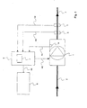
- FIG. 1 shown embodiment of a device according to the invention for the delivery of blood in an extracorporeal circuit comprises a centrifugal pump 1, which sucks the blood to be delivered via a connected to the suction side of the pump venous hose line 2.
- the venous tubing 2 may be directly connected to a patient whose blood is delivered in the extracorporeal blood circulation.
- other components of the circulatory system may be involved in the venous line that may be present in the venous line FIG. 1 but not are shown.
- the centrifugal pump 1 delivers the blood to the arterial section of the extracorporeal blood circulation.
- a flow sensor 5 and a pressure sensor 6 are provided on the arterial side of the pump.
- the flow sensor 5 serves to detect the discharge quantity on the delivery side of the pump 1 and outputs a measurement signal corresponding to the delivery quantity.
- the pressure sensor 6 serves to detect the pressure on the delivery side of the pump 1 and outputs a measurement signal corresponding to the flow rate.
- this point is not critical, since on the arterial side of the pump, an overpressure (compared to the atmospheric pressure) prevails and therefore not to the ingress of air into the arterial tube 3 but possibly to the escape of blood from the Arterial hose 3 may come, if a leak in the area of the measuring point occurs.
- the embodiment of a device according to the invention described here further comprises an evaluation device 4, to which the measurement signal of the flow sensor 5 and the measurement signal of the pressure sensor 6 are supplied.
- the evaluation device is supplied with a further signal, for example the measured value of a rotational speed sensor 1a or the drive signal of the pump, which corresponds to the rotational speed of the centrifugal pump 1.
- FIG. 1 shows, in the embodiment described here, the measurement signals and the further signal of the evaluation device 4 via signal lines 4a to 4c supplied. If the evaluation device 4 is integrated in a control device for controlling the pump, the separate supply of a speed-dependent signal is not required.
- FIG. 1 shows, in the embodiment described here, the measurement signals and the further signal of the evaluation device 4 via signal lines 4a to 4c supplied. If the evaluation device 4 is integrated in a control device for controlling the pump, the separate supply of a speed-dependent signal is not required.
- a drive signal line 4d (shown in dashed lines) is provided, via which the control unit configured in this case as a control device Evaluation device 4 of the pump 1 supplies a drive signal and determined in this way the speed of the pump immediately.
- the evaluation device 4 evaluates the measurement signals and the rotational speed of the centrifugal pump and determines based on the measurement signals and the rotational speed of a value corresponding to the pressure on the suction side of the pump. It is exploited that the pressure rise (gradient outlet pressure inlet pressure) over a centrifugal pump is a function of the speed and the flow, which can be described for example by means of a family of characteristics. Changed resistances on the venous or arterial side of the pump have no influence on this.
- the pressure on the suction side can be determined by first determining the pressure increase across the pump with the help of the characteristic field (and possibly interpolation between support values of the characteristic field) and then the pressure increase determined in this way is subtracted from the pressure on the discharge side of the pump.
- the characteristic curve field must first be determined metrologically for a specific centrifugal pump type.
- the values of the characteristic field are preferably stored in the evaluation device 4 in a memory 7, so that the evaluation devices can access the characteristic field of the centrifugal pump when determining the value corresponding to the pressure on the suction side of the pump, the measurement signals of the sensors on the arterial side and the speed can be used as an access parameter. If a support value for a given parameter combination is not present in the characteristic field, a suitable point in the characteristic field is determined by means of (linear) interpolation.
- an alarm can be issued to an operator via a display device 8, which then takes the appropriate countermeasures to reduce the negative pressure in the venous line.
- the evaluation device 4 is connected to the display device 8 via a signal line 4e. With the help of the display device 8, it is also possible that the evaluation device 4 continuously provides a pressure reading at least for the negative pressure on the venous side of the pump, so that the operator receives an overview of the current pressure conditions during operation.
- the evaluation device 4 also assumes the function of a control device or is integrated in a control device, in the event of excessive negative pressure on the venous side of the centrifugal pump, the pump can intervene directly and the rotational speed can be lowered in order to reduce the negative pressure in the venous Reduce the lead.
- the already mentioned drive signal line 4 d can be used for the supply of a corresponding drive signal to the pump 1.
Landscapes
- Health & Medical Sciences (AREA)
- Heart & Thoracic Surgery (AREA)
- Engineering & Computer Science (AREA)
- Cardiology (AREA)
- Veterinary Medicine (AREA)
- Public Health (AREA)
- Biomedical Technology (AREA)
- Hematology (AREA)
- Life Sciences & Earth Sciences (AREA)
- Animal Behavior & Ethology (AREA)
- General Health & Medical Sciences (AREA)
- Anesthesiology (AREA)
- Mechanical Engineering (AREA)
- Vascular Medicine (AREA)
- Medical Informatics (AREA)
- Physics & Mathematics (AREA)
- Fluid Mechanics (AREA)
- External Artificial Organs (AREA)
Description
Die Erfindung betrifft eine Vorrichtung zur Förderung von Blut in einem extrakorporalen Kreislauf mit einer Zentrifugalpumpe.The invention relates to a device for delivering blood in an extracorporeal circuit with a centrifugal pump.
Die Förderung von Blut in einem extrakorporalen Blutkreislauf mit einer Zentrifugalpumpe ist bekannt, beispielsweise aus
Jedoch ist die Erfassung des Unterdrucks auf der venösen Seite der Pumpe problematisch, da es wegen des hier herrschenden Unterdrucks (gegenüber dem Atmosphärendruck) zum Eindringen von Luft in den Blutkreislauf kommen kann, wenn am Ort des Drucksensors Undichtigkeiten auftreten. Die Erkennung von eindringender Luft aufgrund dieser Problematik ist praktisch nicht durchführbar; gleichzeitig stellt Luft, die in den extrakorporalen Blutkreislauf gelangt, eine erhebliche Bedrohung für den Patienten dar.However, the detection of the negative pressure on the venous side of the pump is problematic because it can come because of the negative pressure prevailing here (with respect to the atmospheric pressure) to the ingress of air into the blood circulation, if leaks occur at the location of the pressure sensor. The detection of air ingress due to this problem is practically not feasible; At the same time, air that enters the extracorporeal bloodstream constitutes one significant threat to the patient.
Das der Erfindung zugrunde liegende Problem besteht vor diesem Hintergrund darin, einen Weg anzugeben, wie ein zuverlässiger Wert, der der Höhe des Unterdrucks auf der Ansaugseite der Pumpe entspricht, erhalten werden kann, ohne dazu einen Drucksensor auf der venösen Seite der Pumpe einzusetzen.Against this background, the problem underlying the invention is to provide a way in which a reliable value, which corresponds to the level of negative pressure on the suction side of the pump, can be obtained without using a pressure sensor on the venous side of the pump.
Gelöst wird dieses Problem durch eine Vorrichtung zur Förderung von Blut in einem extrakorporalen Kreislauf mit einer Zentrifugalpumpe, die das zu fördernde Blut über eine an der Ansaugseite der Pumpe angeschlossene venöse Schlauchleitung ansaugt und über eine an der Abgabeseite der Pumpe angeschlossene arterielle Schlauchleitung abgibt, mit einem Durchflusssensor, der zur Erfassung der Abgabemenge auf der Abgabeseite der Pumpe vorgesehen ist und der ein der Abgabemenge entsprechendes Messsignal abgibt, mit einem Drucksensor, der zur Erfassung des Druckes auf der Abgabeseite der Pumpe vorgesehen ist und der ein dem Druck entsprechendes Messsignal abgibt, und mit einer Auswerteeinrichtung, der das Messsignal des Durchflusssensors und das Messsignal des Drucksensors zugeführt werden und die unter Einbeziehung der beiden Messsignale und der Drehzahl der Zentrifugalpumpe einen dem Druck auf der Ansaugseite der Pumpe entsprechenden Wert ermittelt.This problem is solved by a device for delivering blood in an extracorporeal circuit with a centrifugal pump, which sucks the blood to be delivered via a connected to the suction side of the pump venous line and emits a connected to the discharge side of the pump arterial tubing, with a Flow sensor, which is provided for detecting the discharge amount on the discharge side of the pump and which emits a discharge of the corresponding measurement signal, with a pressure sensor which is provided for detecting the pressure on the discharge side of the pump and which emits a pressure corresponding to the measurement signal, and with an evaluation device to which the measurement signal of the flow sensor and the measurement signal of the pressure sensor are supplied and which determines a value corresponding to the pressure on the suction side of the pump by including the two measurement signals and the rotational speed of the centrifugal pump.
In einer vorteilhaften Ausgestaltung nutzt die Auswerteeinrichtung bei der Ermittlung des dem Druck auf der Ansaugseite der Pumpe entsprechenden Werts ein Kennlinienfeld der Zentrifugalpumpe.In an advantageous embodiment, the evaluation device uses a characteristic field of the centrifugal pump in determining the value corresponding to the pressure on the suction side of the pump.
In einer weiteren vorteilhaften Ausgestaltung ist in der Auswerteeinrichtung das Kennlinienfeld der Zentrifugalpumpe in einem Speicher abgelegt.In a further advantageous embodiment, the characteristic field of the centrifugal pump is stored in a memory in the evaluation device.
In einer weiteren vorteilhaften Ausgestaltung ist die Auswerteeinrichtung mit einer Anzeigeeinrichtung für die Anzeige zumindest des Unterdrucks auf der Ansaugseite der Pumpe und/oder für die Alarmierung einer Bedienperson verbunden.In a further advantageous embodiment, the evaluation device with a display device for the display of at least the negative pressure on the suction side of Pump and / or connected to the alarm of an operator.
In einer weiteren vorteilhaften Ausgestaltung wird der Auswerteeinrichtung ein Messsignal eines Drehzahlsensors zugeführt wird.In a further advantageous embodiment, the evaluation device is supplied with a measurement signal of a rotational speed sensor.
In einer weiteren vorteilhaften Ausgestaltung wird der Auswerteeinrichtung ein Ansteuersignal der Pumpe zugeführt, das die Drehzahl der Pumpe bestimmt bzw. repräsentiert.In a further advantageous embodiment of the evaluation is supplied to a drive signal of the pump, which determines or represents the speed of the pump.
In einer weiteren vorteilhaften Ausgestaltung nimmt die Auswerteeinrichtung die Funktion einer Steuereinrichtung für die Zentrifugalpumpe wahr oder ist in eine Steuereinrichtung für die Zentrifugalpumpe integriert, so dass ein die Drehzahl der Zentrifugalpumpe bestimmendes Ansteuersignal der Zentrifugalpumpe zuführbar ist.In a further advantageous embodiment, the evaluation device performs the function of a control device for the centrifugal pump or is integrated in a control device for the centrifugal pump, so that a rotational speed of the centrifugal pump-determining drive signal of the centrifugal pump can be fed.
In einer weiteren vorteilhaften Ausgestaltung reduziert die Auswerteeinrichtung die Drehzahl der Pumpe beim Auftreten eines vorgegebenen Wertes für den Druck auf der Ansaugseite der Pumpe.In a further advantageous embodiment, the evaluation device reduces the rotational speed of the pump when a predetermined value for the pressure on the suction side of the pump occurs.
Im Folgenden wird ein Ausführungsbeispiel der Erfindung unter Bezugnahme auf die Zeichnung genauer beschrieben.
- Figur 1
- zeigt den Aufbau eines Ausführungsbeispiels einer erfindungsgemäßen Vorrichtung.
- FIG. 1
- shows the structure of an embodiment of a device according to the invention.
Das in
Auf der arteriellen Seite der Pumpe sind ein Durchflusssensor 5 und ein Drucksensor 6 vorgesehen. Der Durchflusssensor 5 dient zur Erfassung der Abgabemenge auf der Abgabeseite der Pumpe 1 und gibt ein der Abgabemenge entsprechendes Messsignal ab. Der Drucksensor 6 dient zur Erfassung des Druckes auf der Abgabeseite der Pumpe 1 und gibt ein der Durchflussmenge entsprechendes Messsignal ab. Bezüglich des Drucksensors 6 ist zu beachten, dass diese Messstelle unkritisch ist, da auf der arteriellen Seite der Pumpe ein Überdruck (gegenüber dem Atmosphärendruck) herrscht und es deshalb nicht zum Eindringen von Luft in die arterielle Schlauchleitung 3 sondern allenfalls zum Austreten von Blut aus der arteriellen Schlauchleitung 3 kommen kann, sofern eine Undichtigkeit im Bereich der Messstelle auftritt.On the arterial side of the pump, a
Wie
In jedem Fall aber wertet die Auswerteeinrichtung 4 die Messsignale und die Drehzahl der Zentrifugalpumpe aus und ermittelt auf der Grundlage der Messsignale und der Drehzahl einen Wert, der dem Druck auf der Ansaugseite der Pumpe entspricht. Dabei wird ausgenutzt, dass der Druckanstieg (Gradient Auslassdruck-Einlassdruck) über einer Zentrifugalpumpe eine Funktion der Drehzahl und des Flusses ist, die zum Beispiel mit Hilfe eines Kennlinienfeldes beschrieben werden kann. Veränderter Widerstände auf der venösen oder der arteriellen Seite der Pumpe haben darauf keinen Einfluss. Somit kann bei bekanntem Druck auf der Abgabeseite, sowie bekanntem Fluss und bekannter Drehzahl der Druck auf der Ansaugseite ermittelt werden, indem zunächst der Druckanstieg über der Pumpe mit Hilfe des Kennlinienfelds (und gegebenenfalls Interpolation zwischen Stützwerten des Kennlinienfelds) bestimmt und danach der so bestimmte Druckanstieg von dem Druck auf der Abgabeseite der Pumpe subtrahiert wird.In any case, the
Das Kennlinienfeld muss für einen bestimmten Zentrifugalpumpentyp zuvor messtechnisch ermittelt werden. Die Werte des Kennlinienfeldes werden in der Auswerteeinrichtung 4 vorzugsweise in einem Speicher 7 abgelegt, so dass die Auswerteeinrichtungen bei der Ermittlung des dem Druck auf der Ansaugseite der Pumpe entsprechenden Werts auf das Kennlinienfeld der Zentrifugalpumpe zugreifen kann, wobei die Messsignale der Sensoren auf der arteriellen Seite und die Drehzahl als Zugriffsparameter verwendet werden können. Sofern ein Stützwert bei einer gegebenen Parameterkombination im Kennlinienfeld nicht vorhanden ist, wird ein geeigneter Punkt im Kennlinienfeld mit Hilfe von (linearer) Interpolation bestimmt.The characteristic curve field must first be determined metrologically for a specific centrifugal pump type. The values of the characteristic field are preferably stored in the
Wenn die Auswerteinrichtung 4 einen übermäßigen Unterdruck auf der venösen Seite der Zentrifugalpumpe ermittelt, kann über eine Anzeigeeinrichtung 8 ein Alarmhinweis an eine Bedienperson ausgegeben werden, die dann die geeigneten Gegenmaßnahmen trifft, um den Unterdruck in der venösen Leitung zu reduzieren. Die Auswerteeinrichtung 4 ist dazu über eine Signalleitung 4e mit der Anzeigeeinrichtung 8 verbunden. Mit Hilfe der Anzeigeeinrichtung 8 ist es ferner möglich, dass die Auswerteeinrichtung 4 kontinuierlich eine Druckanzeige zumindest für den Unterdruck auf der venösen Seite der Pumpe liefert, so dass die Bedienperson im laufenden Betrieb einen Überblick über die aktuellen Druckverhältnisse erhält.If the
Sofern wie oben beschrieben die Auswerteeinrichtung 4 auch die Funktion einer Steuereinrichtung übernimmt oder in eine Steuereinrichtung integriert ist, kann bei einem übermäßigen Unterdruck auf der venösen Seite der Zentrifugalpumpe direkt in den Betrieb der Pumpe eingegriffen und die Drehzahl abgesenkt werden, um den Unterdruck in der venösen Leitung zu verringern. Für die Zuführung eines entsprechenden Ansteuersignals zur Pumpe 1 kann die bereits angesprochene Ansteuersignalleitung 4d verwendet werden.If, as described above, the
Claims (8)
- Apparatus for the transport of blood in an extracorporeal circuit, having- a centrifugal pump which draws in the blood to be transported via a venous tube (2) connected to the intake side of the pump and delivers it via an arterial tube (3) connected to the delivery side of the pump,- a flow sensor (5) which is provided for detecting the delivered quantity on the delivery side of the pump (1) and which emits a measurement signal corresponding to the delivered quantity,- a pressure sensor (6) which is provided for detecting the pressure on the delivery side of the pump (1) and which emits a measurement signal corresponding to the pressure,
characterised by- an evaluating device (4) to which the measurement signal of the flow sensor (5) and the measurement signal of the pressure sensor (6) are delivered, and which, taking into account the two measurement signals and the speed of rotation of the centrifugal pump, determines a value corresponding to the pressure on the intake side of the pump. - Apparatus according to claim 1, in which the evaluating device (4), on determining the value corresponding to the pressure on the intake side of the pump, accesses a family of characteristics of the centrifugal pump.
- Apparatus according to claim 2, in which in the evaluating device (4) the family of characteristics of the centrifugal pump is filed in a memory (7).
- Apparatus according to any of claims 1 to 3, in which the evaluating device (4) is connected to an indicator device (8) for indicating at least the partial pressure on the intake side of the pump (1) and/or for alerting an operator.
- Apparatus according to any of claims 1 to 3, in which a measurement signal of a speed sensor (1a) is delivered to the evaluating device (4).
- Apparatus according to any of claims 1 to 3, in which a drive signal for the pump (1) which corresponds to the speed of the pump is delivered to the evaluating device (4).
- Apparatus according to any of claims 1 to 4, in which the evaluating device (4) performs the function of a control device for the centrifugal pump (1) or is integrated in a control device for the centrifugal pump (1), so that a drive signal which determines the speed of the centrifugal pump (1) can be delivered to the centrifugal pump.
- Apparatus according to claim 7, in which the evaluating device (4) reduces the speed of the pump (1) when a predetermined value for the pressure occurs on the intake side of the pump.
Applications Claiming Priority (2)
| Application Number | Priority Date | Filing Date | Title |
|---|---|---|---|
| DE102009027195A DE102009027195A1 (en) | 2009-06-25 | 2009-06-25 | Device for pumping blood in an extracorporeal circuit |
| PCT/EP2010/055444 WO2010149408A1 (en) | 2009-06-25 | 2010-04-23 | Device for pumping blood in an extracorporeal circuit |
Publications (2)
| Publication Number | Publication Date |
|---|---|
| EP2445545A1 EP2445545A1 (en) | 2012-05-02 |
| EP2445545B1 true EP2445545B1 (en) | 2014-08-13 |
Family
ID=42537527
Family Applications (1)
| Application Number | Title | Priority Date | Filing Date |
|---|---|---|---|
| EP10718535.7A Active EP2445545B1 (en) | 2009-06-25 | 2010-04-23 | Device for pumping blood in an extracorporeal circuit |
Country Status (7)
| Country | Link |
|---|---|
| US (1) | US9452250B2 (en) |
| EP (1) | EP2445545B1 (en) |
| JP (1) | JP5687696B2 (en) |
| CN (1) | CN102458499B (en) |
| BR (1) | BRPI1011644A2 (en) |
| DE (1) | DE102009027195A1 (en) |
| WO (1) | WO2010149408A1 (en) |
Cited By (1)
| Publication number | Priority date | Publication date | Assignee | Title |
|---|---|---|---|---|
| US10220132B2 (en) | 2014-12-19 | 2019-03-05 | Fenwal, Inc. | Biological fluid flow control apparatus and method |
Families Citing this family (12)
| Publication number | Priority date | Publication date | Assignee | Title |
|---|---|---|---|---|
| DE102010011798B4 (en) * | 2010-03-17 | 2017-07-13 | Fresenius Medical Care Deutschland Gmbh | Method and device for determining the pressure or volume flow of medical fluids |
| DE102011112221B4 (en) * | 2011-09-02 | 2017-05-24 | Fresenius Medical Care Deutschland Gmbh | Blood treatment device |
| EP2785392B1 (en) | 2011-12-03 | 2017-04-12 | Indiana University Research and Technology Corporation | Cavopulmonary viscous impeller assist device and method |
| DE102013006562A1 (en) * | 2013-04-16 | 2014-10-16 | Fresenius Medical Care Deutschland Gmbh | Method for determining the pressure in an extracorporeal circuit |
| DE102014000678A1 (en) * | 2014-01-22 | 2015-07-23 | Fresenius Medical Care Deutschland Gmbh | Device and method for regulating and specifying the pumping rate of blood pumps |
| DE102014105473A1 (en) | 2014-04-16 | 2015-10-22 | Fresenius Medical Care Deutschland Gmbh | Method for removing blood from an extracorporeal blood circulation under pressure control as well as devices |
| CN104207857B (en) * | 2014-09-05 | 2016-08-24 | 浙江大学 | Ischemic limb controlling perfusion system |
| WO2016092913A1 (en) * | 2014-12-12 | 2016-06-16 | テルモ株式会社 | Extracorporeal circulation device |
| DE102015005179B4 (en) * | 2015-04-22 | 2022-07-28 | Fresenius Medical Care Deutschland Gmbh | Dialysis machine and method for operating a pneumatic system of a dialysis machine |
| EP3315150B1 (en) * | 2015-06-24 | 2020-12-09 | Nikkiso Co., Ltd. | Blood purifying device |
| DE102016011819A1 (en) * | 2016-10-05 | 2018-04-05 | W.O.M. World Of Medicine Gmbh | Method and device for the intraoperative determination of the resistance coefficients of various medical instruments when using a medical fluid pump |
| JP7236436B2 (en) * | 2018-03-20 | 2023-03-09 | テルモ株式会社 | Measuring system and computing unit |
Family Cites Families (154)
| Publication number | Priority date | Publication date | Assignee | Title |
|---|---|---|---|---|
| NL6811762A (en) | 1968-08-17 | 1970-02-19 | ||
| US3551072A (en) * | 1969-01-31 | 1970-12-29 | Ladish Co | Variable speed motor driven pumping system |
| US3927980A (en) | 1973-08-22 | 1975-12-23 | Baxter Laboratories Inc | Oxygen overpressure protection system for membrane-type blood oxygenators |
| US3851181A (en) | 1973-11-07 | 1974-11-26 | Audronics Inc | Blood level detector |
| DE2455229A1 (en) | 1974-11-21 | 1976-05-26 | Stoeckert Instr Apparatebau Gm | Partial bypass cardiopulmonary machine - has blood reservoir with analog level indicator controlling reservoir level by pump speed control |
| US4170765A (en) | 1975-04-17 | 1979-10-09 | Marvtek, Corporation | Liquid level sensor |
| US4006745A (en) | 1975-05-22 | 1977-02-08 | Sorenson Research Co., Inc. | Autologous transfusion system and method |
| US4177649A (en) * | 1977-11-01 | 1979-12-11 | Borg-Warner Corporation | Surge suppression apparatus for compressor-driven system |
| US4309871A (en) * | 1977-11-01 | 1982-01-12 | Borg-Warner Corporation | Control apparatus for controlling surge in air compressor-driven system |
| DE2754894C2 (en) | 1977-12-09 | 1983-10-13 | Fresenius AG, 6380 Bad Homburg | Device for balancing a fluid withdrawn from a patient with a replacement fluid |
| US4193004A (en) | 1978-06-22 | 1980-03-11 | Cobe Laboratories, Inc. | Fluid level monitoring through fluid cell protrusion |
| US4466804A (en) | 1981-09-25 | 1984-08-21 | Tsunekazu Hino | Extracorporeal circulation of blood |
| US4448207A (en) | 1981-11-03 | 1984-05-15 | Vital Metrics, Inc. | Medical fluid measuring system |
| US4490331A (en) | 1982-02-12 | 1984-12-25 | Steg Jr Robert F | Extracorporeal blood processing system |
| US4599093A (en) | 1982-02-12 | 1986-07-08 | Steg Jr Robert F | Extracorporeal blood processing system |
| US4518318A (en) * | 1983-07-07 | 1985-05-21 | Grundfos A/S | Pumping sets |
| US4678404A (en) * | 1983-10-28 | 1987-07-07 | Hughes Tool Company | Low volume variable rpm submersible well pump |
| DE3485552D1 (en) | 1983-11-11 | 1992-04-09 | Terumo Corp | DEVICE FOR TAKING AND TREATING BLOOD. |
| US4701101A (en) | 1984-03-13 | 1987-10-20 | Catalyst Technology, Inc. | Modular multi-tube catalyst loading funnel |
| US4642089A (en) | 1985-01-29 | 1987-02-10 | Shiley, Inc. | Unitary venous return reservoir with cardiotomy filter |
| JPS61276562A (en) | 1985-05-31 | 1986-12-06 | テルモ株式会社 | Blood storage tank |
| US4828543A (en) | 1986-04-03 | 1989-05-09 | Weiss Paul I | Extracorporeal circulation apparatus |
| US5110549A (en) | 1986-07-14 | 1992-05-05 | Baxter International Inc. | Liquid and gas separation system |
| US4876066A (en) | 1986-07-14 | 1989-10-24 | Baxter International Inc. | Integrated membrane oxygenator, heat exchanger and reservoir |
| JPS6411560A (en) | 1987-07-07 | 1989-01-17 | Terumo Corp | Blood storage tank |
| US5078677A (en) | 1987-09-29 | 1992-01-07 | Conmed Corporation | Apparatus for collecting blood from a chest drainage unit and reinfusion of the blood |
| US4846800A (en) | 1987-10-14 | 1989-07-11 | Kenneth Ouriel | Two chambered autotransfuser device and method of use |
| IT1223470B (en) | 1987-12-15 | 1990-09-19 | Dideco Spa | INTEGRATED UNIT IN EXTRACORPOREAL BLOOD CIRCUIT |
| DE3828441A1 (en) | 1988-08-22 | 1990-03-15 | Heinze Werner | LEVEL MEASUREMENT DEVICE FOR BLOOD RESERVOIRS, IN PARTICULAR OF HUMAN MEDICAL DEVICES |
| US4955874A (en) | 1988-09-27 | 1990-09-11 | Pfizer Hospital Products Group, Inc. | Drainage device |
| EP0371173A1 (en) | 1988-11-03 | 1990-06-06 | BAXTER INTERNATIONAL INC. (a Delaware corporation) | Integral blood defoamer, reservoir, heat exchanger, and cardiotomy filter |
| US5226265A (en) | 1989-03-22 | 1993-07-13 | The Burke Company | Apparatus and method for lifting tilt-up wall constructions |
| US4984462A (en) | 1989-05-30 | 1991-01-15 | Meditor Corporation | Detachable liquid level monitoring apparatus and method |
| US5049146A (en) | 1989-05-31 | 1991-09-17 | Baxter International, Inc. | Blood/gas separator and flow system |
| US4991433A (en) | 1989-09-21 | 1991-02-12 | Applied Acoustic Research | Phase track system for monitoring fluid material within a container |
| US5186431A (en) | 1989-09-22 | 1993-02-16 | Yehuda Tamari | Pressure sensitive valves for extracorporeal circuits |
| DE3935502C2 (en) | 1989-10-25 | 1995-04-13 | Heimes Horst Peter Dr Ing | Encapsulated liquid pump |
| US5039430A (en) | 1989-11-20 | 1991-08-13 | Medtronic, Inc. | Method and apparatus for combining cardiotomy and venous blood |
| JPH0628134Y2 (en) | 1990-01-05 | 1994-08-03 | 泉工医科工業株式会社 | Liquid level control device for blood reservoir |
| US5055198A (en) | 1990-03-07 | 1991-10-08 | Shettigar U Ramakrishna | Autologous blood recovery membrane system and method |
| US5215519A (en) | 1990-03-07 | 1993-06-01 | Shettigar U Ramakrishna | Autotransfusion membrane system with means for providing reverse filtration |
| US5149318A (en) | 1990-03-14 | 1992-09-22 | Minnesota Mining And Manufacturing Company | Quick-changeover blood handling apparatus |
| EP0452827B1 (en) * | 1990-04-16 | 1995-08-02 | Nikkiso Co., Ltd. | Blood pump and extracorporeal blood circulating apparatus |
| US5061236A (en) | 1990-07-16 | 1991-10-29 | Baxter International Inc. | Venous reservoir with improved inlet configuration and integral screen for bubble removal |
| US5178603A (en) | 1990-07-24 | 1993-01-12 | Baxter International, Inc. | Blood extraction and reinfusion flow control system and method |
| US5227049A (en) | 1990-08-20 | 1993-07-13 | Hospal Industrie | Single-needle circuit for circulating blood outside the body in blood treatment apparatus |
| US5270005A (en) | 1990-09-07 | 1993-12-14 | Baxter International Inc. | Extracorporeal blood oxygenation system incorporating integrated reservoir-membrane oxygenerator-heat exchanger and pump assembly |
| CN1052916C (en) | 1990-11-30 | 2000-05-31 | 黎浩钧 | Medical flexible parts and related method and apparatus for controlling curvity |
| US5158533A (en) | 1991-03-26 | 1992-10-27 | Gish Biomedical, Inc. | Combined cardiotomy/venous/pleural drainage autotransfusion unit with filter and integral manometer and water seal |
| US5240380A (en) * | 1991-05-21 | 1993-08-31 | Sundstrand Corporation | Variable speed control for centrifugal pumps |
| US5318510A (en) | 1991-06-11 | 1994-06-07 | Deknatel Technology Corporation, Inc. | Collection device |
| US5586085A (en) | 1991-10-31 | 1996-12-17 | Lichte; Leo J. | Container and adaptor for use with fluid volume sensor |
| US5303585A (en) | 1991-10-31 | 1994-04-19 | Jtl Medical Corporation | Fluid volume sensor |
| US5282783A (en) | 1991-12-17 | 1994-02-01 | Minnesota Mining And Manufacturing Company | Blood reservoir |
| US5403273A (en) | 1991-12-17 | 1995-04-04 | Minnesota Mining And Manufacturing Company | Blood reservoir |
| US5458579A (en) | 1991-12-31 | 1995-10-17 | Technalytics, Inc. | Mechanical trocar insertion apparatus |
| US5399074A (en) * | 1992-09-04 | 1995-03-21 | Kyocera Corporation | Motor driven sealless blood pump |
| US5458566A (en) | 1993-03-24 | 1995-10-17 | Haemonetics, Inc. | Reservoir volume sensing systems for autologous blood recovery |
| KR100344716B1 (en) * | 1993-09-20 | 2002-11-23 | 가부시키 가이샤 에바라 세이사꾸쇼 | Pump operation control device |
| US5411705A (en) | 1994-01-14 | 1995-05-02 | Avecor Cardiovascular Inc. | Combined cardiotomy and venous blood reservoir |
| US5823986A (en) | 1995-02-08 | 1998-10-20 | Medtronic, Inc. | Perfusion system |
| FR2730767B1 (en) * | 1995-02-21 | 1997-04-18 | Inst Francais Du Petrole | METHOD AND DEVICE FOR REGULATING A POLYPHASIC PUMPING ASSEMBLY |
| US5725357A (en) * | 1995-04-03 | 1998-03-10 | Ntn Corporation | Magnetically suspended type pump |
| US6652495B1 (en) | 1995-04-10 | 2003-11-25 | Kenneth Gordon Walker | System for disposal of fluids |
| US5667485A (en) | 1995-05-01 | 1997-09-16 | Minnesota Mining And Manufacturing Company | Blood reservoir with visible inlet tube |
| WO1999015212A1 (en) * | 1997-09-24 | 1999-04-01 | The Cleveland Clinic Foundation | Flow controlled blood pump system |
| CN1147964A (en) | 1995-10-17 | 1997-04-23 | 郭伟 | Composition electrode connecting conduct |
| US5770073A (en) | 1996-03-15 | 1998-06-23 | Minntech Corporation | Combined cardiotomy and venous reservoir |
| IT1283482B1 (en) | 1996-07-22 | 1998-04-21 | Dideco Spa | COMBINED DEVICE INCLUDING VENOUS BLOOD TANK AND CARDIOTOME IN EXTRA-BODY CIRCUIT |
| US5826576A (en) | 1996-08-08 | 1998-10-27 | Medtronic, Inc. | Electrophysiology catheter with multifunction wire and method for making |
| US5800721A (en) | 1996-08-30 | 1998-09-01 | Baxter International Inc. | Combined cardiotomy fluid and venous blood reservoir |
| US5813972A (en) | 1996-09-30 | 1998-09-29 | Minnesota Mining And Manufacturing Company | Medical perfusion system with data communications network |
| US5849186A (en) | 1996-11-15 | 1998-12-15 | C. R. Bard Inc. | Integrated cardiotomy and venous blood reservoir |
| US5955672A (en) | 1997-04-29 | 1999-09-21 | Medtronic, Inc. | Ultrasonic blood volume measurement in soft-shell venous reservoir |
| WO1998048868A1 (en) | 1997-04-29 | 1998-11-05 | Medtronic, Inc. | Ultrasonic blood volume measurement soft-shell venous reservoir |
| US5823045A (en) | 1997-04-29 | 1998-10-20 | Medtronic, Inc. | Measuring blood volume in soft-shell venous resevoirs by displacement |
| US6048363A (en) * | 1997-05-13 | 2000-04-11 | Nagyszalanczy; Lorant | Centrifugal blood pump apparatus |
| US6017493A (en) | 1997-09-26 | 2000-01-25 | Baxter International Inc. | Vacuum-assisted venous drainage reservoir for CPB systems |
| DE69827266T2 (en) | 1997-08-15 | 2005-10-13 | Baxter International Inc., Deerfield | SYSTEM FOR MINIMALLY INVASIVE SURGERY WITH VACUUM-SUPPORTED VENOUS DRAINAGE |
| JP3919896B2 (en) * | 1997-09-05 | 2007-05-30 | テルモ株式会社 | Centrifugal liquid pump device |
| CN1121242C (en) | 1998-01-12 | 2003-09-17 | 周国明 | Bottom-placed blood plane and density dynamic monitoring system for artificial lung |
| JP4051812B2 (en) | 1998-04-13 | 2008-02-27 | 株式会社ジェイ・エム・エス | Extracorporeal circulation device with control function |
| DE19817995C1 (en) | 1998-04-22 | 1999-09-09 | Stoeckert Instr Gmbh | Filling level monitoring device for blood reservoir for medical transfusion apparatus |
| US6592340B1 (en) * | 1998-06-11 | 2003-07-15 | Sulzer Pumpen Ag | Control system for a vacuum pump used for removing liquid and a method of controlling said pump |
| WO1999065413A1 (en) | 1998-06-13 | 1999-12-23 | Pfefferkorn & Co. Gmbh | Pressure element for exerting a pressure on a surface |
| US6337049B1 (en) | 1998-08-28 | 2002-01-08 | Yehuda Tamari | Soft shell venous reservoir |
| DE19841612A1 (en) | 1998-09-11 | 2000-03-16 | Argomedical Ag | Shoulder joint implant, comprising of three main elements, can be infinitely variable moved, in order to create realistic motion of upper arm |
| DK199900119A (en) | 1999-01-29 | 2000-09-04 | Polystan Holding As | Pressure regulator for vacuum assisted drainage |
| AUPP995999A0 (en) * | 1999-04-23 | 1999-05-20 | University Of Technology, Sydney | Non-contact estimation and control system |
| EP1053760A3 (en) | 1999-05-21 | 2001-08-16 | Medtronic, Inc. | Fully constrained soft shell reservoir |
| EP1070509A3 (en) | 1999-07-23 | 2002-04-24 | Medtronic, Inc. | Safety device for vacuum-assisted venous drainage |
| US7225809B1 (en) * | 1999-11-01 | 2007-06-05 | Ric Investments, Llc | Method and apparatus for monitoring and controlling a medical device |
| FR2802799B1 (en) | 1999-12-23 | 2002-08-16 | Depuy France | SHOULDER PROSTHESIS KIT |
| US6347633B1 (en) * | 2000-01-14 | 2002-02-19 | First Circle Medical, Inc. | Treatment of hepatitis C using hyperthermia |
| JP4332969B2 (en) | 2000-01-31 | 2009-09-16 | 株式会社ジェイ・エム・エス | Blood reservoir |
| CA2672076A1 (en) | 2000-03-01 | 2001-09-07 | Caridianbct, Inc. | Extracorporeal blood processing information management system |
| CA2404636A1 (en) * | 2000-03-27 | 2001-10-04 | The Cleveland Clinic Foundation | Chronic performance control system for rotodynamic blood pumps |
| EP1191959A2 (en) | 2000-04-06 | 2002-04-03 | Cobe Cardiovascular, Inc. | Assembly for extracorporeal blood handling and method of use |
| SE515604C2 (en) | 2000-04-28 | 2001-09-10 | Bst Ab | Method and apparatus for suction and transport of liquids, preferably blood |
| EP1322352A4 (en) | 2000-09-27 | 2010-06-16 | Sorin Group Usa Inc | Disposable cartridge for a blood perfusion system |
| US20080027368A1 (en) | 2000-09-27 | 2008-01-31 | Sorin Group Usa, Inc. | Disposable cartridge for a blood perfusion system |
| US6585675B1 (en) | 2000-11-02 | 2003-07-01 | Chf Solutions, Inc. | Method and apparatus for blood withdrawal and infusion using a pressure controller |
| DE50102226D1 (en) | 2000-11-16 | 2004-06-09 | Willi Horber | ENDOPROTHESIS FOR A SHOULDER JOINT |
| ATE285730T1 (en) | 2000-11-16 | 2005-01-15 | Willi Horber | JOINT PROSTHESIS |
| JP2002165878A (en) | 2000-11-30 | 2002-06-11 | Terumo Corp | Blood storage tank |
| EP1210956B1 (en) | 2000-11-30 | 2007-02-14 | Terumo Kabushiki Kaisha | Blood reservoir |
| JP4590161B2 (en) | 2001-05-21 | 2010-12-01 | スコット・ラボラトリーズ・インコーポレイテッド | RF-ID label for medical container |
| EP1284369A1 (en) * | 2001-08-16 | 2003-02-19 | Levitronix LLC | Method for delivering variable amounts of flow, and dosing pumping using this method |
| US6623420B2 (en) * | 2001-08-16 | 2003-09-23 | Apex Medical, Inc. | Physiological heart pump control |
| US6631639B1 (en) | 2001-09-07 | 2003-10-14 | Cosense, Inc | System and method of non-invasive discreet, continuous and multi-point level liquid sensing using flexural waves |
| EP1429823A1 (en) | 2001-09-27 | 2004-06-23 | Gambro, Inc., | Radio frequency or electromagnetic information systems and methods for use in extracorporeal blood processing |
| JP4132777B2 (en) | 2001-10-25 | 2008-08-13 | 川澄化学工業株式会社 | Artificial lung blood reservoir |
| US6564627B1 (en) * | 2002-01-17 | 2003-05-20 | Itt Manufacturing Enterprises, Inc. | Determining centrifugal pump suction conditions using non-traditional method |
| US6694570B2 (en) | 2002-03-11 | 2004-02-24 | Compal Electronics, Inc. | Hinge device |
| ITMI20020526A1 (en) | 2002-03-12 | 2003-09-12 | Dideco Spa | VENOUS BLOOD TANK IN EXTRACORPOREAL CIRCUIT |
| US7284956B2 (en) * | 2002-09-10 | 2007-10-23 | Miwatec Co., Ltd. | Methods and apparatus for controlling a continuous flow rotary blood pump |
| US20040062658A1 (en) * | 2002-09-27 | 2004-04-01 | Beck Thomas L. | Control system for progressing cavity pumps |
| ATE472355T1 (en) | 2002-12-03 | 2010-07-15 | Toagosei Co Ltd | METHOD FOR PRODUCING A SEALING PART ON A FILTRATION ELEMENT |
| AU2003903138A0 (en) * | 2003-06-20 | 2003-07-03 | Resmed Limited | Method and apparatus for improving the comfort of cpap |
| JP2005066013A (en) | 2003-08-25 | 2005-03-17 | Miwatec:Kk | Method and apparatus for controlling continuous flow rotary blood pump |
| US7364563B2 (en) * | 2003-10-02 | 2008-04-29 | Minnetronix, Inc. | Continuous volume detection for a flexible venous reservoir in a cardiopulmonary bypass circuit |
| EP1720585A4 (en) | 2004-01-22 | 2008-12-31 | Yehuda Tamari | A colsed venous -cardiotomy reservoir with improved air handling |
| JP2006025531A (en) | 2004-07-07 | 2006-01-26 | Seiko Instruments Inc | Dc/dc converter circuit |
| DE102004040441A1 (en) | 2004-08-20 | 2006-06-14 | Disetronic Licensing Ag | Apparatus and method for determining the level of an ampoule |
| US7519432B2 (en) | 2004-10-21 | 2009-04-14 | Medtronic, Inc. | Implantable medical lead with helical reinforcement |
| DE102005001779B4 (en) | 2005-01-14 | 2009-12-17 | Fresenius Medical Care Deutschland Gmbh | Disposable for operating a blood treatment device in single-needle or two-needle operation |
| ES2348407T3 (en) * | 2005-05-18 | 2010-12-03 | Gambro Lundia Ab | APPLIANCE TO CONTROL THE BLOOD FLOW IN AN EXTRACORPORE CIRCUIT. |
| JP2006325750A (en) | 2005-05-24 | 2006-12-07 | Senko Medical Instr Mfg Co Ltd | Blood circulation system and its controller |
| US8231749B2 (en) | 2005-06-02 | 2012-07-31 | Automed Technologies, Inc. | Apparatus and methods for dispensing pre-filled containers with precisely-applied patient-specific information |
| DE102005029682A1 (en) | 2005-06-21 | 2006-12-28 | Maquet Cardiopulmonary Ag | Heart/lung bypass, for patients on a heart/lung machine, has a reservoir for priming solution and/or blood |
| RU2293176C1 (en) * | 2005-09-02 | 2007-02-10 | Николай Петрович Кузьмичев | Method for short-term operation of well using immersed pump device with electric drive |
| US20070142923A1 (en) * | 2005-11-04 | 2007-06-21 | Ayre Peter J | Control systems for rotary blood pumps |
| JP4500764B2 (en) | 2005-11-11 | 2010-07-14 | テルモ株式会社 | Extracorporeal circulation device |
| WO2007140481A2 (en) * | 2006-05-31 | 2007-12-06 | Richard Wampler | Heart assist device |
| US8187214B2 (en) | 2006-10-30 | 2012-05-29 | Lifebridge Medizintechnik Ag | Apparatus for making extracorporeal blood circulation available |
| JP4867692B2 (en) | 2007-02-15 | 2012-02-01 | 株式会社ジェイ・エム・エス | Cardiotomy filter and blood reservoir |
| US7694570B1 (en) | 2007-03-30 | 2010-04-13 | Cosense, Inc | Non-invasive dry coupled disposable/reusable ultrasonic sensor |
| GB0706382D0 (en) | 2007-04-02 | 2007-05-09 | Huntleigh Technology Plc | Fluid level sensor |
| JP2008270595A (en) | 2007-04-23 | 2008-11-06 | Texas Instr Japan Ltd | Reaction product peeling preventive structure and manufacturing method thereof, and manufacturing method of semiconductor device using the structure |
| DE102007026010B4 (en) | 2007-06-04 | 2010-11-25 | Fresenius Medical Care Deutschland Gmbh | Device for controlling a device for delivering blood and method for conveying blood in a blood line of an extracorporeal blood circulation of an extracorporeal blood treatment device |
| WO2009049235A2 (en) | 2007-10-12 | 2009-04-16 | Deka Products Limited Partnership | Systems, devices and methods for cardiopulmonary treatment and procedures |
| JP4830064B2 (en) | 2008-03-28 | 2011-12-07 | 静岡県 | Infusion measurement system |
| AU2008357106B2 (en) * | 2008-05-26 | 2013-02-07 | Gambro Lundia Ab | A hemodialysis or hemo(dia)filtration apparatus and a method for controlling a hemodialysis or hemo(dia)filtration apparatus |
| JP5083622B2 (en) | 2008-05-27 | 2012-11-28 | 株式会社ジェイテクト | Tapered roller bearings |
| US8202240B2 (en) | 2008-08-12 | 2012-06-19 | Caridianbct, Inc. | System and method for collecting plasma protein fractions from separated blood components |
| BRPI0920392B8 (en) | 2008-10-09 | 2021-06-22 | Nipro Corp | blood reservoir |
| US8177072B2 (en) | 2008-12-04 | 2012-05-15 | Thermogenesis Corp. | Apparatus and method for separating and isolating components of a biological fluid |
| EP2248935B1 (en) * | 2009-05-04 | 2011-08-10 | Coprecitec, S.L. | Washing household appliance and control method thereof |
| DE102009026592B4 (en) | 2009-05-29 | 2014-08-28 | Sorin Group Deutschland Gmbh | Device for determining the venous inflow to a blood reservoir of an extracorporeal blood circulation |
| JP2011076394A (en) | 2009-09-30 | 2011-04-14 | Seiko Epson Corp | Printer, printing program and printing method |
| US8734376B2 (en) | 2010-04-20 | 2014-05-27 | Sorin Group Italia S.R.L. | Perfusion system with RFID |
| US8506513B2 (en) | 2010-04-20 | 2013-08-13 | Sorin Group Italia S.R.L. | Blood reservoir with ultrasonic volume sensor |
| US8500673B2 (en) | 2010-04-20 | 2013-08-06 | Sorin Group Italia S.R.L. | Blood reservoir with level sensor |
| EP2754458B1 (en) | 2011-07-12 | 2017-02-01 | Sorin Group Italia S.r.l. | Dual chamber blood reservoir |
-
2009
- 2009-06-25 DE DE102009027195A patent/DE102009027195A1/en not_active Ceased
-
2010
- 2010-04-23 US US13/380,165 patent/US9452250B2/en active Active
- 2010-04-23 EP EP10718535.7A patent/EP2445545B1/en active Active
- 2010-04-23 CN CN201080028491.0A patent/CN102458499B/en active Active
- 2010-04-23 JP JP2012516595A patent/JP5687696B2/en active Active
- 2010-04-23 WO PCT/EP2010/055444 patent/WO2010149408A1/en active Application Filing
- 2010-04-23 BR BRPI1011644A patent/BRPI1011644A2/en not_active Application Discontinuation
Cited By (1)
| Publication number | Priority date | Publication date | Assignee | Title |
|---|---|---|---|---|
| US10220132B2 (en) | 2014-12-19 | 2019-03-05 | Fenwal, Inc. | Biological fluid flow control apparatus and method |
Also Published As
| Publication number | Publication date |
|---|---|
| DE102009027195A1 (en) | 2010-12-30 |
| BRPI1011644A2 (en) | 2016-10-25 |
| EP2445545A1 (en) | 2012-05-02 |
| CN102458499A (en) | 2012-05-16 |
| US9452250B2 (en) | 2016-09-27 |
| US20120150089A1 (en) | 2012-06-14 |
| CN102458499B (en) | 2015-06-17 |
| JP5687696B2 (en) | 2015-03-18 |
| WO2010149408A1 (en) | 2010-12-29 |
| JP2012530569A (en) | 2012-12-06 |
Similar Documents
| Publication | Publication Date | Title |
|---|---|---|
| EP2445545B1 (en) | Device for pumping blood in an extracorporeal circuit | |
| EP1749549B1 (en) | System for drainage of cerebrospinal fluid | |
| DE102011112221B4 (en) | Blood treatment device | |
| EP1564411B1 (en) | Method for detecting operation errors of a pump aggregate | |
| DE19840399B4 (en) | A centrifugal fluid pump | |
| EP2178437B1 (en) | Device for monitoring an access to a patient | |
| EP2600917B1 (en) | Device with a peristaltic hose pump | |
| DE2802247C2 (en) | ||
| DE3806248C2 (en) | ||
| EP2893945B1 (en) | Dialysis machine with leakage detection and a method of detecting leaks of dialysis fluid systems | |
| DE102013017828B4 (en) | Method and device for monitoring an in an extracorporeal blood circulation or arranged in a Dialysatkreislauf impeller pump and blood treatment device | |
| DE102013012504B4 (en) | Method for monitoring an extracorporeal blood treatment and device for carrying out the method | |
| DE102011102872B4 (en) | Blood treatment device | |
| EP1960017B1 (en) | Method for blowing free a wetted hydrophobic filter, and device for carrying out the method | |
| EP0943805B1 (en) | Process and sensor for cavitation detection as well as a device comprising such sensor | |
| DE102014102732A1 (en) | System and method for detecting a venous needle disconnection | |
| DE102013221137B3 (en) | Cooling system for a vehicle battery | |
| DE10033192B4 (en) | Method for detecting arterial enema problems during extracorporeal blood treatment and extracorporeal blood treatment device | |
| EP3285823B1 (en) | Method for conveying a medium with a pump and pump comprising a rotor, a housing and a drive | |
| EP3088016A1 (en) | Pump and method for operating a pump for liquids | |
| DE202014101752U1 (en) | Pressure monitoring and alarm device of a medical vacuum wound care system | |
| EP3914314A1 (en) | Method for checking the delivery accuracy of delivery means of a medical treatment system, and systems | |
| EP3543537A1 (en) | Pump unit and method for monitoring the liquid situation in a seal assembly in a pump unit | |
| DE102013020747A1 (en) | Apparatus and method for monitoring venous vascular access in extracorporeal blood treatment | |
| WO2015049056A1 (en) | Medical device and method for detecting the fill level of a bubble chamber |
Legal Events
| Date | Code | Title | Description |
|---|---|---|---|
| PUAI | Public reference made under article 153(3) epc to a published international application that has entered the european phase |
Free format text: ORIGINAL CODE: 0009012 |
|
| 17P | Request for examination filed |
Effective date: 20111213 |
|
| AK | Designated contracting states |
Kind code of ref document: A1 Designated state(s): AT BE BG CH CY CZ DE DK EE ES FI FR GB GR HR HU IE IS IT LI LT LU LV MC MK MT NL NO PL PT RO SE SI SK SM TR |
|
| DAX | Request for extension of the european patent (deleted) | ||
| GRAP | Despatch of communication of intention to grant a patent |
Free format text: ORIGINAL CODE: EPIDOSNIGR1 |
|
| INTG | Intention to grant announced |
Effective date: 20140307 |
|
| GRAS | Grant fee paid |
Free format text: ORIGINAL CODE: EPIDOSNIGR3 |
|
| GRAA | (expected) grant |
Free format text: ORIGINAL CODE: 0009210 |
|
| AK | Designated contracting states |
Kind code of ref document: B1 Designated state(s): AT BE BG CH CY CZ DE DK EE ES FI FR GB GR HR HU IE IS IT LI LT LU LV MC MK MT NL NO PL PT RO SE SI SK SM TR |
|
| REG | Reference to a national code |
Ref country code: GB Ref legal event code: FG4D Free format text: NOT ENGLISH |
|
| REG | Reference to a national code |
Ref country code: AT Ref legal event code: REF Ref document number: 681796 Country of ref document: AT Kind code of ref document: T Effective date: 20140815 Ref country code: CH Ref legal event code: EP |
|
| REG | Reference to a national code |
Ref country code: IE Ref legal event code: FG4D Free format text: LANGUAGE OF EP DOCUMENT: GERMAN |
|
| REG | Reference to a national code |
Ref country code: DE Ref legal event code: R096 Ref document number: 502010007655 Country of ref document: DE Effective date: 20140925 |
|
| REG | Reference to a national code |
Ref country code: NL Ref legal event code: T3 |
|
| REG | Reference to a national code |
Ref country code: LT Ref legal event code: MG4D |
|
| PG25 | Lapsed in a contracting state [announced via postgrant information from national office to epo] |
Ref country code: ES Free format text: LAPSE BECAUSE OF FAILURE TO SUBMIT A TRANSLATION OF THE DESCRIPTION OR TO PAY THE FEE WITHIN THE PRESCRIBED TIME-LIMIT Effective date: 20140813 Ref country code: BG Free format text: LAPSE BECAUSE OF FAILURE TO SUBMIT A TRANSLATION OF THE DESCRIPTION OR TO PAY THE FEE WITHIN THE PRESCRIBED TIME-LIMIT Effective date: 20141113 Ref country code: NO Free format text: LAPSE BECAUSE OF FAILURE TO SUBMIT A TRANSLATION OF THE DESCRIPTION OR TO PAY THE FEE WITHIN THE PRESCRIBED TIME-LIMIT Effective date: 20141113 Ref country code: SE Free format text: LAPSE BECAUSE OF FAILURE TO SUBMIT A TRANSLATION OF THE DESCRIPTION OR TO PAY THE FEE WITHIN THE PRESCRIBED TIME-LIMIT Effective date: 20140813 Ref country code: GR Free format text: LAPSE BECAUSE OF FAILURE TO SUBMIT A TRANSLATION OF THE DESCRIPTION OR TO PAY THE FEE WITHIN THE PRESCRIBED TIME-LIMIT Effective date: 20141114 Ref country code: LT Free format text: LAPSE BECAUSE OF FAILURE TO SUBMIT A TRANSLATION OF THE DESCRIPTION OR TO PAY THE FEE WITHIN THE PRESCRIBED TIME-LIMIT Effective date: 20140813 Ref country code: PT Free format text: LAPSE BECAUSE OF FAILURE TO SUBMIT A TRANSLATION OF THE DESCRIPTION OR TO PAY THE FEE WITHIN THE PRESCRIBED TIME-LIMIT Effective date: 20141215 Ref country code: FI Free format text: LAPSE BECAUSE OF FAILURE TO SUBMIT A TRANSLATION OF THE DESCRIPTION OR TO PAY THE FEE WITHIN THE PRESCRIBED TIME-LIMIT Effective date: 20140813 |
|
| PG25 | Lapsed in a contracting state [announced via postgrant information from national office to epo] |
Ref country code: CY Free format text: LAPSE BECAUSE OF FAILURE TO SUBMIT A TRANSLATION OF THE DESCRIPTION OR TO PAY THE FEE WITHIN THE PRESCRIBED TIME-LIMIT Effective date: 20140813 Ref country code: IS Free format text: LAPSE BECAUSE OF FAILURE TO SUBMIT A TRANSLATION OF THE DESCRIPTION OR TO PAY THE FEE WITHIN THE PRESCRIBED TIME-LIMIT Effective date: 20141213 Ref country code: HR Free format text: LAPSE BECAUSE OF FAILURE TO SUBMIT A TRANSLATION OF THE DESCRIPTION OR TO PAY THE FEE WITHIN THE PRESCRIBED TIME-LIMIT Effective date: 20140813 Ref country code: LV Free format text: LAPSE BECAUSE OF FAILURE TO SUBMIT A TRANSLATION OF THE DESCRIPTION OR TO PAY THE FEE WITHIN THE PRESCRIBED TIME-LIMIT Effective date: 20140813 |
|
| PG25 | Lapsed in a contracting state [announced via postgrant information from national office to epo] |
Ref country code: EE Free format text: LAPSE BECAUSE OF FAILURE TO SUBMIT A TRANSLATION OF THE DESCRIPTION OR TO PAY THE FEE WITHIN THE PRESCRIBED TIME-LIMIT Effective date: 20140813 Ref country code: DK Free format text: LAPSE BECAUSE OF FAILURE TO SUBMIT A TRANSLATION OF THE DESCRIPTION OR TO PAY THE FEE WITHIN THE PRESCRIBED TIME-LIMIT Effective date: 20140813 Ref country code: SK Free format text: LAPSE BECAUSE OF FAILURE TO SUBMIT A TRANSLATION OF THE DESCRIPTION OR TO PAY THE FEE WITHIN THE PRESCRIBED TIME-LIMIT Effective date: 20140813 Ref country code: CZ Free format text: LAPSE BECAUSE OF FAILURE TO SUBMIT A TRANSLATION OF THE DESCRIPTION OR TO PAY THE FEE WITHIN THE PRESCRIBED TIME-LIMIT Effective date: 20140813 Ref country code: RO Free format text: LAPSE BECAUSE OF FAILURE TO SUBMIT A TRANSLATION OF THE DESCRIPTION OR TO PAY THE FEE WITHIN THE PRESCRIBED TIME-LIMIT Effective date: 20140813 |
|
| REG | Reference to a national code |
Ref country code: DE Ref legal event code: R097 Ref document number: 502010007655 Country of ref document: DE |
|
| PG25 | Lapsed in a contracting state [announced via postgrant information from national office to epo] |
Ref country code: PL Free format text: LAPSE BECAUSE OF FAILURE TO SUBMIT A TRANSLATION OF THE DESCRIPTION OR TO PAY THE FEE WITHIN THE PRESCRIBED TIME-LIMIT Effective date: 20140813 |
|
| PLBE | No opposition filed within time limit |
Free format text: ORIGINAL CODE: 0009261 |
|
| STAA | Information on the status of an ep patent application or granted ep patent |
Free format text: STATUS: NO OPPOSITION FILED WITHIN TIME LIMIT |
|
| 26N | No opposition filed |
Effective date: 20150515 |
|
| PG25 | Lapsed in a contracting state [announced via postgrant information from national office to epo] |
Ref country code: LU Free format text: LAPSE BECAUSE OF FAILURE TO SUBMIT A TRANSLATION OF THE DESCRIPTION OR TO PAY THE FEE WITHIN THE PRESCRIBED TIME-LIMIT Effective date: 20150423 Ref country code: MC Free format text: LAPSE BECAUSE OF FAILURE TO SUBMIT A TRANSLATION OF THE DESCRIPTION OR TO PAY THE FEE WITHIN THE PRESCRIBED TIME-LIMIT Effective date: 20140813 Ref country code: SI Free format text: LAPSE BECAUSE OF FAILURE TO SUBMIT A TRANSLATION OF THE DESCRIPTION OR TO PAY THE FEE WITHIN THE PRESCRIBED TIME-LIMIT Effective date: 20140813 |
|
| REG | Reference to a national code |
Ref country code: CH Ref legal event code: PL |
|
| REG | Reference to a national code |
Ref country code: IE Ref legal event code: MM4A |
|
| PG25 | Lapsed in a contracting state [announced via postgrant information from national office to epo] |
Ref country code: LI Free format text: LAPSE BECAUSE OF NON-PAYMENT OF DUE FEES Effective date: 20150430 Ref country code: CH Free format text: LAPSE BECAUSE OF NON-PAYMENT OF DUE FEES Effective date: 20150430 |
|
| REG | Reference to a national code |
Ref country code: FR Ref legal event code: PLFP Year of fee payment: 7 |
|
| PG25 | Lapsed in a contracting state [announced via postgrant information from national office to epo] |
Ref country code: IE Free format text: LAPSE BECAUSE OF NON-PAYMENT OF DUE FEES Effective date: 20150423 |
|
| REG | Reference to a national code |
Ref country code: AT Ref legal event code: MM01 Ref document number: 681796 Country of ref document: AT Kind code of ref document: T Effective date: 20150423 |
|
| PG25 | Lapsed in a contracting state [announced via postgrant information from national office to epo] |
Ref country code: AT Free format text: LAPSE BECAUSE OF NON-PAYMENT OF DUE FEES Effective date: 20150423 |
|
| PG25 | Lapsed in a contracting state [announced via postgrant information from national office to epo] |
Ref country code: MT Free format text: LAPSE BECAUSE OF FAILURE TO SUBMIT A TRANSLATION OF THE DESCRIPTION OR TO PAY THE FEE WITHIN THE PRESCRIBED TIME-LIMIT Effective date: 20140813 |
|
| REG | Reference to a national code |
Ref country code: FR Ref legal event code: PLFP Year of fee payment: 8 |
|
| PG25 | Lapsed in a contracting state [announced via postgrant information from national office to epo] |
Ref country code: HU Free format text: LAPSE BECAUSE OF FAILURE TO SUBMIT A TRANSLATION OF THE DESCRIPTION OR TO PAY THE FEE WITHIN THE PRESCRIBED TIME-LIMIT; INVALID AB INITIO Effective date: 20100423 Ref country code: SM Free format text: LAPSE BECAUSE OF FAILURE TO SUBMIT A TRANSLATION OF THE DESCRIPTION OR TO PAY THE FEE WITHIN THE PRESCRIBED TIME-LIMIT Effective date: 20140813 |
|
| PG25 | Lapsed in a contracting state [announced via postgrant information from national office to epo] |
Ref country code: BE Free format text: LAPSE BECAUSE OF NON-PAYMENT OF DUE FEES Effective date: 20150430 |
|
| PG25 | Lapsed in a contracting state [announced via postgrant information from national office to epo] |
Ref country code: TR Free format text: LAPSE BECAUSE OF FAILURE TO SUBMIT A TRANSLATION OF THE DESCRIPTION OR TO PAY THE FEE WITHIN THE PRESCRIBED TIME-LIMIT Effective date: 20140813 |
|
| REG | Reference to a national code |
Ref country code: FR Ref legal event code: PLFP Year of fee payment: 9 |
|
| PG25 | Lapsed in a contracting state [announced via postgrant information from national office to epo] |
Ref country code: MK Free format text: LAPSE BECAUSE OF FAILURE TO SUBMIT A TRANSLATION OF THE DESCRIPTION OR TO PAY THE FEE WITHIN THE PRESCRIBED TIME-LIMIT Effective date: 20140813 |
|
| REG | Reference to a national code |
Ref country code: DE Ref legal event code: R082 Ref document number: 502010007655 Country of ref document: DE Representative=s name: GRUENECKER PATENT- UND RECHTSANWAELTE PARTG MB, DE |
|
| PGFP | Annual fee paid to national office [announced via postgrant information from national office to epo] |
Ref country code: NL Payment date: 20200417 Year of fee payment: 11 |
|
| REG | Reference to a national code |
Ref country code: DE Ref legal event code: R079 Ref document number: 502010007655 Country of ref document: DE Free format text: PREVIOUS MAIN CLASS: A61M0001100000 Ipc: A61M0060000000 |
|
| REG | Reference to a national code |
Ref country code: NL Ref legal event code: MM Effective date: 20210501 |
|
| PG25 | Lapsed in a contracting state [announced via postgrant information from national office to epo] |
Ref country code: NL Free format text: LAPSE BECAUSE OF NON-PAYMENT OF DUE FEES Effective date: 20210501 |
|
| PGFP | Annual fee paid to national office [announced via postgrant information from national office to epo] |
Ref country code: FR Payment date: 20230309 Year of fee payment: 14 |
|
| PGFP | Annual fee paid to national office [announced via postgrant information from national office to epo] |
Ref country code: IT Payment date: 20230310 Year of fee payment: 14 |
|
| P01 | Opt-out of the competence of the unified patent court (upc) registered |
Effective date: 20230516 |
|
| PGFP | Annual fee paid to national office [announced via postgrant information from national office to epo] |
Ref country code: DE Payment date: 20230307 Year of fee payment: 14 |
|
| PGFP | Annual fee paid to national office [announced via postgrant information from national office to epo] |
Ref country code: GB Payment date: 20240229 Year of fee payment: 15 |