EP1749549B1 - System for drainage of cerebrospinal fluid - Google Patents
System for drainage of cerebrospinal fluid Download PDFInfo
- Publication number
- EP1749549B1 EP1749549B1 EP05016789A EP05016789A EP1749549B1 EP 1749549 B1 EP1749549 B1 EP 1749549B1 EP 05016789 A EP05016789 A EP 05016789A EP 05016789 A EP05016789 A EP 05016789A EP 1749549 B1 EP1749549 B1 EP 1749549B1
- Authority
- EP
- European Patent Office
- Prior art keywords
- liquor
- pressure
- pump
- drainage
- operating
- Prior art date
- Legal status (The legal status is an assumption and is not a legal conclusion. Google has not performed a legal analysis and makes no representation as to the accuracy of the status listed.)
- Active
Links
- 210000001175 cerebrospinal fluid Anatomy 0.000 title claims abstract description 84
- 238000001514 detection method Methods 0.000 claims description 5
- 230000003287 optical effect Effects 0.000 claims description 4
- 238000012544 monitoring process Methods 0.000 claims description 3
- 239000012530 fluid Substances 0.000 abstract description 15
- 238000000034 method Methods 0.000 abstract description 7
- 238000005259 measurement Methods 0.000 abstract description 3
- 210000004556 brain Anatomy 0.000 description 20
- 230000002572 peristaltic effect Effects 0.000 description 14
- 238000005086 pumping Methods 0.000 description 9
- 230000008569 process Effects 0.000 description 6
- 230000002490 cerebral effect Effects 0.000 description 5
- 239000007788 liquid Substances 0.000 description 4
- 210000003625 skull Anatomy 0.000 description 4
- 238000011156 evaluation Methods 0.000 description 3
- 230000008901 benefit Effects 0.000 description 2
- 238000009530 blood pressure measurement Methods 0.000 description 2
- 230000008878 coupling Effects 0.000 description 2
- 238000010168 coupling process Methods 0.000 description 2
- 238000005859 coupling reaction Methods 0.000 description 2
- 208000003906 hydrocephalus Diseases 0.000 description 2
- 230000002706 hydrostatic effect Effects 0.000 description 2
- XLYOFNOQVPJJNP-UHFFFAOYSA-N water Substances O XLYOFNOQVPJJNP-UHFFFAOYSA-N 0.000 description 2
- 206010022773 Intracranial pressure increased Diseases 0.000 description 1
- 208000007536 Thrombosis Diseases 0.000 description 1
- 230000001154 acute effect Effects 0.000 description 1
- 238000011511 automated evaluation Methods 0.000 description 1
- 230000005540 biological transmission Effects 0.000 description 1
- 230000015572 biosynthetic process Effects 0.000 description 1
- 239000008280 blood Substances 0.000 description 1
- 210000004369 blood Anatomy 0.000 description 1
- 230000036772 blood pressure Effects 0.000 description 1
- 238000011109 contamination Methods 0.000 description 1
- 230000002950 deficient Effects 0.000 description 1
- 230000001419 dependent effect Effects 0.000 description 1
- 230000036512 infertility Effects 0.000 description 1
- 238000007917 intracranial administration Methods 0.000 description 1
- 210000004705 lumbosacral region Anatomy 0.000 description 1
- 239000000463 material Substances 0.000 description 1
- 230000000474 nursing effect Effects 0.000 description 1
- 238000010926 purge Methods 0.000 description 1
- 230000001105 regulatory effect Effects 0.000 description 1
- 230000004044 response Effects 0.000 description 1
- 238000005096 rolling process Methods 0.000 description 1
- 230000035945 sensitivity Effects 0.000 description 1
- 230000002123 temporal effect Effects 0.000 description 1
- 238000012546 transfer Methods 0.000 description 1
- 210000003462 vein Anatomy 0.000 description 1
- 230000000007 visual effect Effects 0.000 description 1
Images
Classifications
-
- A—HUMAN NECESSITIES
- A61—MEDICAL OR VETERINARY SCIENCE; HYGIENE
- A61M—DEVICES FOR INTRODUCING MEDIA INTO, OR ONTO, THE BODY; DEVICES FOR TRANSDUCING BODY MEDIA OR FOR TAKING MEDIA FROM THE BODY; DEVICES FOR PRODUCING OR ENDING SLEEP OR STUPOR
- A61M27/00—Drainage appliance for wounds or the like, i.e. wound drains, implanted drains
- A61M27/002—Implant devices for drainage of body fluids from one part of the body to another
- A61M27/006—Cerebrospinal drainage; Accessories therefor, e.g. valves
-
- A—HUMAN NECESSITIES
- A61—MEDICAL OR VETERINARY SCIENCE; HYGIENE
- A61M—DEVICES FOR INTRODUCING MEDIA INTO, OR ONTO, THE BODY; DEVICES FOR TRANSDUCING BODY MEDIA OR FOR TAKING MEDIA FROM THE BODY; DEVICES FOR PRODUCING OR ENDING SLEEP OR STUPOR
- A61M1/00—Suction or pumping devices for medical purposes; Devices for carrying-off, for treatment of, or for carrying-over, body-liquids; Drainage systems
- A61M1/71—Suction drainage systems
- A61M1/73—Suction drainage systems comprising sensors or indicators for physical values
-
- A—HUMAN NECESSITIES
- A61—MEDICAL OR VETERINARY SCIENCE; HYGIENE
- A61M—DEVICES FOR INTRODUCING MEDIA INTO, OR ONTO, THE BODY; DEVICES FOR TRANSDUCING BODY MEDIA OR FOR TAKING MEDIA FROM THE BODY; DEVICES FOR PRODUCING OR ENDING SLEEP OR STUPOR
- A61M1/00—Suction or pumping devices for medical purposes; Devices for carrying-off, for treatment of, or for carrying-over, body-liquids; Drainage systems
- A61M1/71—Suction drainage systems
- A61M1/74—Suction control
-
- F—MECHANICAL ENGINEERING; LIGHTING; HEATING; WEAPONS; BLASTING
- F04—POSITIVE - DISPLACEMENT MACHINES FOR LIQUIDS; PUMPS FOR LIQUIDS OR ELASTIC FLUIDS
- F04B—POSITIVE-DISPLACEMENT MACHINES FOR LIQUIDS; PUMPS
- F04B43/00—Machines, pumps, or pumping installations having flexible working members
- F04B43/12—Machines, pumps, or pumping installations having flexible working members having peristaltic action
- F04B43/1253—Machines, pumps, or pumping installations having flexible working members having peristaltic action by using two or more rollers as squeezing elements, the rollers moving on an arc of a circle during squeezing
-
- A—HUMAN NECESSITIES
- A61—MEDICAL OR VETERINARY SCIENCE; HYGIENE
- A61B—DIAGNOSIS; SURGERY; IDENTIFICATION
- A61B5/00—Measuring for diagnostic purposes; Identification of persons
- A61B5/03—Detecting, measuring or recording fluid pressure within the body other than blood pressure, e.g. cerebral pressure; Measuring pressure in body tissues or organs
- A61B5/031—Intracranial pressure
-
- A—HUMAN NECESSITIES
- A61—MEDICAL OR VETERINARY SCIENCE; HYGIENE
- A61M—DEVICES FOR INTRODUCING MEDIA INTO, OR ONTO, THE BODY; DEVICES FOR TRANSDUCING BODY MEDIA OR FOR TAKING MEDIA FROM THE BODY; DEVICES FOR PRODUCING OR ENDING SLEEP OR STUPOR
- A61M2210/00—Anatomical parts of the body
- A61M2210/06—Head
- A61M2210/0693—Brain, cerebrum
-
- F—MECHANICAL ENGINEERING; LIGHTING; HEATING; WEAPONS; BLASTING
- F04—POSITIVE - DISPLACEMENT MACHINES FOR LIQUIDS; PUMPS FOR LIQUIDS OR ELASTIC FLUIDS
- F04B—POSITIVE-DISPLACEMENT MACHINES FOR LIQUIDS; PUMPS
- F04B2205/00—Fluid parameters
- F04B2205/01—Pressure before the pump inlet
Definitions
- the invention relates generally to a device for drainage of cerebrospinal fluid, and more particularly to a cerebrospinal fluid drainage system according to the preamble of claim 1.
- CSF drainage arrangement normally consists of a brain catheter which is introduced through a skull into the cerebral cavity (ventricle) to be treated and connected to a drainage conduit to the outside or to the desired body cavity or vein.
- cerebral water is about 500 ml / day, with the pressure of the cerebrospinal fluid in the lumbar region of the brain as well as in the brain ventricles a constant value within certain limits.
- a reduced pressure of the brain fluid in the skull of the patient should be produced with the help of the drainage device, wherein the desired during the treatment lower pressure of the cerebrospinal fluid (CSF pressure) should be below the brain blood pressure.
- CSF pressure cerebrospinal fluid
- An external CSF drainage arrangement is for example from DE 296 21 904 U1 in which a so-called balancing chamber is mounted on a height-adjustable stand in which the drained liquid is collected and its volume is determined. Due to the sensitivity of the brain to pressure, it is extremely important for the drainage of cerebrospinal fluid or cerebrospinal fluid to maintain a given drainage pressure. Therefore, the balance chamber of the known CSF drainage assembly must be accurately aligned to a certain height relative to the head of the patient.
- the cerebrospinal fluid line is equipped with a pressure transducer, which measures the current pressure of the cerebrospinal fluid in the cerebrospinal fluid line.
- the drainage pressure and thus the hydrostatic pressure in the drainage line and the balancing chamber should not exceed or fall below certain limit values. If the head position of the patient is changed, for example, by pivoting the back part of the bed, the height of the balancing chamber and the pressure transducer must also be adjusted so that on the one hand the pressure measurement is correct and on the other hand the pressure limits are maintained.
- the DE 103 17 308 describes a CSF drainage assembly, which is also arranged on a height-adjustable stand, with an attached to the stand balancing chamber, connected to the balancing chamber CSF supply line, a pressure transducer in the CSF supply line and a direction finder for adjusting the altitude of the tripod.
- a valve having a certain closing pressure is used to control the process of draining the liquor.
- the operating pressure of the existing valve in the discharge device corresponds to the desired liquor pressure.
- the outflow of cerebral fluid from the ventricles occurs as long as the cerebrospinal fluid pressure is above the switching pressure of the valve.
- the monitoring of the pressure with optical sensor means is disclosed.
- the American patent US6336924 discloses an external fluid drainage system.
- the drainage system comprises a two-part drainage catheter.
- the first part is located near the patient's head and the second part near a drainage bag.
- a pressure sensor is housed between the first and second parts of the catheter.
- One end of the first part is inserted into a ventricle of the patient's head for drainage.
- the other end is connected to the pressure sensor.
- a transparent drainage bag is provided. It is also proposed to detect the drained liquid by means of an optical drop counting system.
- External flow control is provided to control flow through the catheter.
- a pump or a controllable valve are proposed. The flow control is controlled electronically as soon as the measured pressure exceeds a threshold value.
- the object is achieved by the liquor drainage system according to the invention.
- the CSF drainage system includes a CSF supply line and a pressure sensor that detects the pressure in the CSF supply line.
- a pump is provided which evacuates the cerebrospinal fluid in response to predetermined operating parameters and measured operational readings, detection means which detect the volume of drained cerebral fluid.
- the detection means is adapted to calculate the drained liquor volume from the rotation of the pump and the tubing diameter.
- the pump is designed to pump out the brain fluid depending on the volume of drained liquor and depending on the pressure measured in the CSF supply line.
- the measurement of the drained liquor volume based on the pumping processes is inexpensive, because it requires no further measuring device for determining the drained liquor volume.
- the combined use of pressure and drained liquor volume to control the pump is more reliable. Because the sole use of the pressure sensor within the CSF supply line can lead to errors. The control of the pump as a function of the drained liquor volume and the measured pressure therefore allows a more accurate and reliable control of the brain pressure.
- a CSF drainage pumping system that can selectively purge a particular liquor volume with a pressure controlled pump. Since the CSF supply line or the brain catheter is directly connected to the brain cavity (ventricle) to be treated, the same pressure prevails in the CSF supply line and in the brain cavity to be treated, which pressure is determined by the pressure sensor arranged in the CSF supply line. For reasons of safety and the accuracy of the CSF pressure measurement, it is also conceivable to provide a plurality of pressure sensors, so that, for example, incorrect or missing measured values of a defective pressure sensor can be replaced by the measured values of an intact pressure sensor. With several pressure sensors, their measured values can be compared with each other to check or improve the measuring accuracy.
- the pump When the cerebral pressure or pressure of the cerebrospinal fluid (CSF) rises above a defined upper value, the pump is preferably activated automatically and a certain volume of cerebrospinal fluid is pumped off until the desired pressure of the cerebrospinal fluid has been established. This process is actively monitored by the pressure sensor (s) installed in the CSF supply line. Once a sufficient volume of brain fluid has been pumped out and the pressure sensor in the CSF supply line detects that the brain pressure has fallen back to a defined lower value, the pump can be stopped automatically.
- the pressure sensor s
- the pressure sensor is equipped with fastening means which allow an arrangement of the pressure sensor in the head region of the patient.
- the pressure sensor can be fastened by means of a headband in the vicinity of the skull bore or can be arranged via an ear hook or clip on the patient's ear.
- the control of the liquor drainage system is advantageously carried out by an electronic control.
- the electronic control the calculations necessary for the operation of the pump are made on the basis of the given operating parameters and the operating measured values or the measured operating data.
- the electronic control of the CSF drainage system is preferably programmable, so that certain operations can be performed, for example, for different medical applications via appropriate software.
- alarm functions can be set up in the electronic control of the CSF drainage system, which alarms in the event of a deviation of the measured operating data from a predetermined range for the pressure or the pump volume by optical and / or acoustic means. Such an alarm signal is expediently passed on via an appropriate interface and electronically to an external monitoring.
- the CSF drainage system comprises input means via which certain operating parameters, such as predetermined pressure limits of CSF pressure or brain pressure in the ventricle to be treated, may be input to the control electronics.
- control electronics and electronic storage means may be provided in which, for example, certain operations of the CSF drainage system can be stored or kept.
- the CSF drainage system may further comprise controls via which the operation of the Pump can be controlled directly. This gives the possibility to control the pump manually, for example, to generate a short term, higher pumping power to eliminate clogging.
- the pressure sensor in the CSF supply line is preferably designed as an electronic pressure sensor, which forwards the pressure measured in the CSF supply line in the form of electrical signals to the control electronics.
- the control electronics Based on the pressure signals supplied by the pressure sensor and the predetermined pressure limits, the control electronics calculates the required operation of the CSF drainage system or the operation of the CSF pump. In particular, the control electronics performs a comparison between the predetermined CSF pressure limits and the pressure in the CSF supply line determined by the pressure sensor. The control electronics decide on the basis of the calculation whether the pump of the CSF drainage system should be activated or deactivated and / or with which pumping power and, if appropriate, over which period of time the CSF drainage pump should be operated.
- a peristaltic pump is preferably used, which has the merit that the pumped liquid within the tube system does not come in contact with any foreign bodies.
- a piezo-pressure sensor is particularly suitable, which can also detect minimal pressure changes using piezoceramic materials and emits as electrical impulses.
- the liquor drainage system is equipped with a hose system with corresponding branches.
- This tubing system includes a cerebrospinal fluid supply (or brain catheter) leading from the patient's head to the pump, and a CSF drain line leading from the pump to a collection bag for collecting the drained liquor.
- the liquor is pumped out selectively, the pumped volume is controlled pressure controlled.
- the pumped volume is controlled pressure controlled.
- a purely volume-controlled liquor drainage as used e.g. necessary for lumbar permanent drainage.
- the tube system of the liquor drainage system is a closed tube system which allows a simultaneous measurement of the pressure via the pressure sensor during the pumping operation.
- the pressure sensor e.g. Disconnections of the hose connections due to acute pressure drop in the hose system or Schlauchokissesionen or hose closures are recorded by very low or very high pressure values during the pumping process.
- the operating data of the CSF drainage system are detected continuously or at intervals.
- the CSF drainage volume can be calculated continuously from the rotation of the pump and the tubing diameter.
- a recording and documentation of the time course of the determined pumping volume and the pressure in the liquor supply line can be done.
- These data can be forwarded for further evaluation by the control electronics of the liquor drainage system to an evaluation unit. This will result in an automated evaluation of the temporal Brain pressure and cerebro-drainage course allows what was possible in previous systems only by reading the fluid level at the collection bag.
- the operational data of the CSF drainage system e.g. the recording and documentation of the time course of the determined pumping volume or the pressure in the liquor supply line, the running time of the pump, the total volume delivered by the pump, the operating mode or the running time of the pump may conveniently be stored in the electronic storage means of the liquor drainage system according to the invention and be retrieved.
- input means may be provided with which the data stored in the storage means of the CSF drainage system are manually deleted.
- the liquor drainage system according to the invention expediently has a visual display via which set operating parameters and / or current measured values of operating data can be displayed.
- the data transfer from the liquor drainage system to an external evaluation unit takes place via an interface, such as e.g. a cable, infrared, or wireless connection or with the help of a memory card / chip.
- the liquor drainage system according to the invention can also be equipped with an additional output for the transmission of operating data, in particular the CSF pressure signal to external display monitors and with a call button for the nursing staff.
- the liquor drainage system is preferably equipped with an accumulator for electrical energy or an accumulator which ensures the operation independent of the mains for at least a few hours and facilitates transport of the patient to the system.
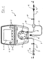
- Figure 1 shows a sketch of the structure of a liquor drainage system according to a preferred embodiment of the present invention.
- the embodiment of the CSF drainage system 1 shown in Fig. 1 comprises, according to the present invention, a main component 2 having a housing 2 in which an electronic control with electronic means for the calculations described above is housed. On the housing 2 input and control elements 3 are arranged, can be entered manually on the required for the operation of the CSF drainage system 1 operating parameters or a desired operating mode of the CSF drainage system. Via a display 4, all entered operating parameters and / or current operating measured values and operating modes of the CSF drainage system 1 can be displayed.
- the main component 2 of the CSF drainage system 1 further comprises a peristaltic pump 5 with connections 6 for hose connections 9 of a hose system.
- the tube connections 9 connected to the peristaltic pump 5 are on the one hand a cerebrospinal fluid supply line (brain catheter) 8 between the peristaltic pump 5 and the patient and on the other hand a hose connection 7 between the peristaltic pump 5 and a discharge bag (not shown) in which collects the pumped cerebrospinal fluid (cerebrospinal fluid).
- the connecting direction of the hose connection 7 to the drainage bag and indicated by the arrow B the connection direction of the hose connection 8 to the patient by the arrow A.
- the hose connections 9 of the hose system have an inner diameter of about 1.0 mm, an outer diameter of about 4.0 mm, a wall thickness of about 1.5 mm and a hardness in the range of 50-55 Shore Have a.
- the peristaltic pump 5 is constructed in a known manner and comprises a flexible circularly arranged pump tube segment.
- the axis of a pump rotor is mounted in the center of the circularly arranged pump tube segment, at the radially outer ends of which rotatably mounted rollers are provided. With the rotation of the pump rotor, the rollers roll on the circular pump tube segment, compressing the pump tube segment.
- a fluid located in the pump hose segment is conveyed in the direction of rotation of the pump rotor.
- Such a peristaltic pump has the advantage that the fluid contained in the tube does not come into contact with foreign bodies and thus contamination of the fluid is excluded.
- a pressure sensor 10 is arranged, which measures the pressure of the liquor in the CSF supply line 8 permanently or at intervals.
- the pressure readings determined by the pressure sensor are converted into electrical signals and forwarded via an electrical line 11 to the electrical control in the main component 2 of the liquor drainage system 1.
- the electrical line 11 is connected by the pressure sensor 10 via a connection 12 to the main component 2 of the liquor drainage system 1 via a corresponding interface (not shown).
- the electrical control of the CSF drainage system 1 uses the operating readings transmitted by the pressure sensor 10 from the pressure in the CSF supply line 8 as a basis for the calculations in the electrical control for controlled operation of the peristaltic pump 5. If, for example, a pressure in the Liquor supply line 8 is detected, which is above a predetermined operating parameter or outside a certain Pressure range is, the electrical control of the CSF drainage system 1, the peristaltic pump 5 can be activated.
- the electrical control can stop the operation of the peristaltic pump 5.
- the CSF drainage system 1 may include detection means which determine the volume of liquor delivered and use the drained liquor volume as the basis for the control of the pump 5. For this purpose, for example, the number of revolutions of the pump rotor can be used, since this is in direct proportion to the funded by the peristaltic pump 5 volume.
- Both the hose connection 7 between the hose pump 5 and the discharge bag and the liquor supply line 8 between the hose pump and the patient can be equipped with a branch, for example in the form of a 3-way valve 17, are connected via the other hose lines to the hose system can.
- the hose connections 9 are respectively connected via suitable hose connection elements 13, 14, 15, 16 to further hose segments or other components of the liquor drainage system 1 which carry liquor liquid.
- the hose connection elements or hose couplings 13, 14, 15, 16 are each designed so that they ensure a pressure-safe connection of the hose connections and thus a closed hose system.
- the hose connection elements or hose couplings 13, 14, 15, 16 may be designed so that they have a disposable use of the hose connections 7, 8 or of the entire Ensure tubing sets, ie that a hose connections 7, 8 can be used only once in the closed-circuit tube to ensure their sterility.
- at least one connecting element 13, 14, 15, 16 may be formed such that the pressure sensor 10 can be received or integrated therein. In this way, the pressure sensor would be placed in direct contact with the liquor in the drainage system and mounted easily replaceable.
- the liquor drainage system 1 is characterized on the one hand by simple operation and on the other hand ensures a controlled liquor drainage process, in which the drained liquor volume regulated as needed and the drainage pressure or the CSF pressure can be reliably maintained within a certain pressure range ,
Abstract
Description
Die Erfindung bezieht sich allgemein auf eine Vorrichtung zur Drainage von Gehirnflüssigkeit und insbesondere auf ein Liquor-Drainagesystem nach dem Oberbegriff des Anspruchs 1.The invention relates generally to a device for drainage of cerebrospinal fluid, and more particularly to a cerebrospinal fluid drainage system according to the preamble of
Bei Patienten mit Hydrocephalus und/oder erhöhtem Hirndruck wird das überschüssige Gehirnwasser (Liquor cerebrospinalis oder kurz: Liquor) entweder mittels internen Drainagevorrichtungen in eine beliebige Körperhöhle oder ins Blut abgeleitet oder mittels externen Drainagevorrichtungen nach außen drainiert. Eine Liquor-Drainageanordnung besteht im Normalfall aus einem Gehirnkatheter, welcher durch eine Schädelbohrung in die zu behandelnde Gehirnhöhle (Ventrikel) eingeführt und an eine Ablaufleitung nach außen oder zu der gewünschten Körperhöhle bzw. Vene angeschlossen wird.In patients with hydrocephalus and / or increased intracranial pressure, the excess cerebrospinal fluid (cerebrospinal fluid, or CSF for short) is either drained into any body cavity or into the blood via internal drainage devices or drained to the outside via external drainage devices. A CSF drainage arrangement normally consists of a brain catheter which is introduced through a skull into the cerebral cavity (ventricle) to be treated and connected to a drainage conduit to the outside or to the desired body cavity or vein.
Die Bildung des Hirnwassers liegt etwa bei 500 ml/Tag, wobei der Druck des Liquors im lumbalen Bereich des Gehirns wie auch in den Gehirnventrikeln einen konstanten Wert innerhalb bestimmter Grenzen aufweist. Bei der Behandlung des Hydrocephalus soll mit Hilfe der Drainagevorrichtung ein reduzierter Druck der Gehirnflüssigkeit im Schädel des Patienten hergestellt werden, wobei der während der Behandlung angestrebte niedrigere Druck der Gehirnflüssigkeit (Liquor-Druck) unterhalb des Hirn-Blutdrucks liegen soll.The formation of cerebral water is about 500 ml / day, with the pressure of the cerebrospinal fluid in the lumbar region of the brain as well as in the brain ventricles a constant value within certain limits. In the treatment of hydrocephalus, a reduced pressure of the brain fluid in the skull of the patient should be produced with the help of the drainage device, wherein the desired during the treatment lower pressure of the cerebrospinal fluid (CSF pressure) should be below the brain blood pressure.
Eine externe Liquor-Drainageanordnung ist beispielsweise aus der
Die
Die
Die bekannten Drainagesysteme arbeiten jedoch trotz der druckabhängigen Regelung des Drainageflusses nicht immer zuverlässig und sind relativ teuer.However, the known drainage systems do not always work reliably despite the pressure-dependent control of the drainage flow and are relatively expensive.
Es ist daher Aufgabe der vorliegenden Erfindung, ein Liquor-Drainagesystem bereizustellen, welches auf zuverlässige und preiswerte Weise für die Drainage von Gehirnflüssigkeit sorgt.It is therefore an object of the present invention to provide a liquor drainage system, which provides in a reliable and inexpensive way for the drainage of cerebrospinal fluid.
Die Aufgabe wird durch das erfindungsgemäße Liquor-Drainagesystem gelöst. Das Liquor-Drainagesystem umfasst eine Liquor-Zulaufleitung und einem Drucksensor, der den Druck in der Liquor-Zulaufleitung ermittelt. Eine Pumpe ist vorgesehen, welche die Gehirnflüssigkeit in Abhängigkeit von vorgegebenen Betriebsparametern und gemessenen Betriebsmesswerten abpumpt, Erfassungsmitteln, die das Volumen der drainierten Gehirnflüssigkeit ermitteln. Das Erfassungsmittel ist dazu ausgebildet, das drainierte Liquor-Volumen aus der Rotation der Pumpe und dem Schlauchdurchmesser zu berechnen. Die Pumpe ist dazu ausgebildet, die Gehirnflüssigkeit in Abhängigkeit von dem drainierten Liquor-Volumen und in Abhängigkeit von dem in der Liquor-Zulaufleitung gemessenen Druck abzupumpen.The object is achieved by the liquor drainage system according to the invention. The CSF drainage system includes a CSF supply line and a pressure sensor that detects the pressure in the CSF supply line. A pump is provided which evacuates the cerebrospinal fluid in response to predetermined operating parameters and measured operational readings, detection means which detect the volume of drained cerebral fluid. The detection means is adapted to calculate the drained liquor volume from the rotation of the pump and the tubing diameter. The pump is designed to pump out the brain fluid depending on the volume of drained liquor and depending on the pressure measured in the CSF supply line.
Die Messung des drainierten Liquorvolumens anhand der Pumprotationen ist preiswert, denn es bedarf keiner weiteren Messvorrichtung zur Ermittlung des drainierten Liquorvolumens. Die kombinierte Verwendung des Drucks und des drainierten Liquor-Volumens zur Steuerung der Pumpe ist zuverlässiger. Denn die alleinige Verwendung des Drucksensors innerhalb der Liquor-Zulaufleitung kann zu Fehlern führen. Die Steuerung der Pumpe in Abhängigkeit von dem drainierten Liquor-Volumen und dem gemessenen Druck erlaubt daher eine genauere und zuverlässigere Regelung des Gehirndrucks.The measurement of the drained liquor volume based on the pumping processes is inexpensive, because it requires no further measuring device for determining the drained liquor volume. The combined use of pressure and drained liquor volume to control the pump is more reliable. Because the sole use of the pressure sensor within the CSF supply line can lead to errors. The control of the pump as a function of the drained liquor volume and the measured pressure therefore allows a more accurate and reliable control of the brain pressure.
Gemäß einer bevorzugten Ausführungsform der vorliegenden Erfindung wird ein Liquor-Drainage-Pumpsystem bereitgestellt, das mit einer druckgesteuerten Pumpe gezielt ein bestimmtes Liquor-Volumen abpumpen kann. Da die Liquor-Zulaufleitung bzw. der Gehirnkatheter direkt mit der zu behandelnden Gehirnhöhle (Ventrikel) verbunden ist, herrscht in der Liquor-Zulaufleitung und in der zu behandelnden Gehirnhöhle der gleiche Druck, der durch den in der Liquor-Zulaufleitung angeordneten Drucksensor ermittelt wird. Aus Gründen der Sicherheit und der Genauigkeit der Liquor-Druckmessung ist es auch denkbar, mehrere Drucksensoren vorzusehen, so dass beispielsweise falsche oder fehlende Messwerte eines defekten Drucksensors durch die Messwerte eines intakten Drucksensors ersetzt werden können. Bei mehreren Drucksensoren können deren Messwerte miteinander abgeglichen werden, um die Messgenauigkeit zu überprüfen oder zu verbessern.According to a preferred embodiment of the present invention, there is provided a CSF drainage pumping system that can selectively purge a particular liquor volume with a pressure controlled pump. Since the CSF supply line or the brain catheter is directly connected to the brain cavity (ventricle) to be treated, the same pressure prevails in the CSF supply line and in the brain cavity to be treated, which pressure is determined by the pressure sensor arranged in the CSF supply line. For reasons of safety and the accuracy of the CSF pressure measurement, it is also conceivable to provide a plurality of pressure sensors, so that, for example, incorrect or missing measured values of a defective pressure sensor can be replaced by the measured values of an intact pressure sensor. With several pressure sensors, their measured values can be compared with each other to check or improve the measuring accuracy.
Wenn der Gehirndruck bzw. der Druck der Gehirnflüssigkeit (Liquor) über einen definierten oberen Wert steigt, wird die Pumpe vorzugsweise automatisch aktiviert und ein bestimmtes Liquor-Volumen abgepumpt bis sich der gewünschte Druck der Gehirnflüssigkeit eingestellt hat. Dieser Vorgang wird aktiv über den/die in der Liquor-Zulaufleitung installierten Drucksensor(en) überwacht. Sobald ein ausreichendes Volumen von Gehirnflüssigkeit abgepumpt wurde und der Drucksensor in der Liquor-Zulaufleitung feststellt, dass der Gehirndruck wieder auf einen definierten unteren Wert gefallen ist, kann die Pumpe automatisch gestoppt werden.When the cerebral pressure or pressure of the cerebrospinal fluid (CSF) rises above a defined upper value, the pump is preferably activated automatically and a certain volume of cerebrospinal fluid is pumped off until the desired pressure of the cerebrospinal fluid has been established. This process is actively monitored by the pressure sensor (s) installed in the CSF supply line. Once a sufficient volume of brain fluid has been pumped out and the pressure sensor in the CSF supply line detects that the brain pressure has fallen back to a defined lower value, the pump can be stopped automatically.
Der Gehirnwasserdruck kann umso besser gemessen werden, je näher der Drucksensor an der Schädelöffnung angeordnet ist. Gemäß einer weiteren vorteilhaften Ausführungsform der vorliegenden Erfindung ist daher der Drucksensor mit Befestigungsmitteln ausgestattet, die eine Anordnung des Drucksensors im Kopfbereich des Patienten ermöglichen. So kann der Drucksensor beispielsweise über ein Stirnband in der Nähe der Schädelbohrung befestigt werden oder über einen Ohrbügel oder Klipp am Ohr des Patienten angeordnet werden.The brain water pressure can be measured the better, the closer the pressure sensor is located at the skull opening. According to a further advantageous embodiment of the present invention, therefore, the pressure sensor is equipped with fastening means which allow an arrangement of the pressure sensor in the head region of the patient. For example, the pressure sensor can be fastened by means of a headband in the vicinity of the skull bore or can be arranged via an ear hook or clip on the patient's ear.
Die Steuerung des Liquor-Drainagesystems erfolgt zweckmäßigerweise durch eine elektronische Steuerung. In der elektronischen Steuerung werden die für den Betrieb der Pumpe erforderlichen Berechnungen aufgrund der vorgegebenen Betriebsparameter und der Betriebsmesswerte bzw. der gemessenen Betriebsdaten vorgenommen. Die elektronische Steuerung des Liquor-Drainagesystems ist vorzugsweise programmierbar, so dass über eine entsprechende Software bestimmte Betriebsabläufe beispielsweise für unterschiedliche medizinische Anwendungen vorgenommen werden können. Ferner können in der elektronischen Steuerung des Liquor-Drainagesystems Alarmfunktionen eingerichtet sein, die bei einer Abweichung der gemessenen Betriebsdaten von einem vorgegebenen Bereich für den Druck oder das Pumpvolumen durch optische und/oder akustische Mittel Alarm geben. Ein solches Alarmsignal wird zweckmäßigerweise über eine entsprechende Schnittstelle auch elektronisch an eine externe Überwachung weitergegeben.The control of the liquor drainage system is advantageously carried out by an electronic control. In the electronic control, the calculations necessary for the operation of the pump are made on the basis of the given operating parameters and the operating measured values or the measured operating data. The electronic control of the CSF drainage system is preferably programmable, so that certain operations can be performed, for example, for different medical applications via appropriate software. Furthermore, alarm functions can be set up in the electronic control of the CSF drainage system, which alarms in the event of a deviation of the measured operating data from a predetermined range for the pressure or the pump volume by optical and / or acoustic means. Such an alarm signal is expediently passed on via an appropriate interface and electronically to an external monitoring.
Gemäß einer bevorzugten Ausführungsform der vorliegenden Erfindung umfasst das Liquor-Drainagesystem Eingabemittel, über die bestimmte Betriebsparameter, wie z.B. vorgegebene Druck-Grenzwerte des Liquor-Drucks bzw. des Gehirndrucks in dem zu behandelnden Ventrikel, in die Steuerungselektronik eingegeben werden können. In der Steuerungselektronik können auch elektronische Speichermittel vorgesehen sein, in denen beispielsweise bestimmte Betriebsabläufe des Liquor-Drainagesystems abgespeichert bzw. vorgehalten werden können. Das Liquor-Drainagesystem kann ferner Bedienungselemente umfassen, über die der Betrieb der Pumpe unmittelbar gesteuert werden kann. Dadurch ist die Möglichkeit gegeben, die Pumpe auch manuell zu steuern, beispielsweise um zur Beseitigung von Verstopfungen kurzfristig eine höhere Pumpleistung zu erzeugen.According to a preferred embodiment of the present invention, the CSF drainage system comprises input means via which certain operating parameters, such as predetermined pressure limits of CSF pressure or brain pressure in the ventricle to be treated, may be input to the control electronics. In the control electronics and electronic storage means may be provided in which, for example, certain operations of the CSF drainage system can be stored or kept. The CSF drainage system may further comprise controls via which the operation of the Pump can be controlled directly. This gives the possibility to control the pump manually, for example, to generate a short term, higher pumping power to eliminate clogging.
Der Drucksensor in der Liquor-Zulaufleitung ist vorzugsweise als elektronischer Drucksensor ausgebildet, der den in der Liquor-Zulaufleitung gemessenen Druck in Form von elektrischen Signalen an die Steuerungselektronik weiterleitet. Aufgrund der vom Drucksensor gelieferten Drucksignale und der vorgegebenen Druck-Grenzwerte berechnet die Steuerungselektronik den erforderlichen Betrieb des Liquor-Drainagesystems bzw. den Betrieb der Liquor-Pumpe. Dabei führt die Steuerungselektronik insbesondere einen Vergleich zwischen den vorgegebenen Liquor-Druckgrenzwerten und dem vom Drucksensor ermittelten Druck in der Liquor-Zulaufleitung durch. Die Steuerungselektronik entscheidet aufgrund der Berechnung, ob die Pumpe des Liquor-Drainagesystems aktiviert oder deaktiviert werden soll und/oder mit welcher Pumpleistung und ggf. über welche Zeitspanne die Liquor-Drainagepumpe betrieben werden soll.The pressure sensor in the CSF supply line is preferably designed as an electronic pressure sensor, which forwards the pressure measured in the CSF supply line in the form of electrical signals to the control electronics. Based on the pressure signals supplied by the pressure sensor and the predetermined pressure limits, the control electronics calculates the required operation of the CSF drainage system or the operation of the CSF pump. In particular, the control electronics performs a comparison between the predetermined CSF pressure limits and the pressure in the CSF supply line determined by the pressure sensor. The control electronics decide on the basis of the calculation whether the pump of the CSF drainage system should be activated or deactivated and / or with which pumping power and, if appropriate, over which period of time the CSF drainage pump should be operated.
Als Pumpe wird zweckmäßigerweise eine Schlauchpumpe verwendet, die den Vorzug hat, dass die gepumpte Flüssigkeit innerhalb des Schlauchssystems nicht mit irgendwelchen Fremdkörpern in Verbindung kommt. Als Drucksensor ist ein Piezo-Drucksensor besonders geeignet, der auch minimale Druckveränderungen mit Hilfe piezokeramischer Materialien ermitteln kann und als elektrische Impulse abgibt.As the pump, a peristaltic pump is preferably used, which has the merit that the pumped liquid within the tube system does not come in contact with any foreign bodies. As a pressure sensor, a piezo-pressure sensor is particularly suitable, which can also detect minimal pressure changes using piezoceramic materials and emits as electrical impulses.
Zur Verbindung der einzelnen flüssigkeitsführenden Komponenten ist das erfindungsgemäße Liquor-Drainagesystem mit einem Schlauchsystem mit entsprechenden Verzweigungen ausgestattet. Dieses Schlauchsystem umfasst eine Liquor-Zulaufleitung bzw. einen Gehirnkatheter, der von dem Kopf des Patienten zur Pumpe führt, sowie eine Liquor-Ablaufleitung, die von der Pumpe zu einem Auffangbeutel zum Auffangen des drainierten Liquors führt.To connect the individual fluid-carrying components, the liquor drainage system according to the invention is equipped with a hose system with corresponding branches. This tubing system includes a cerebrospinal fluid supply (or brain catheter) leading from the patient's head to the pump, and a CSF drain line leading from the pump to a collection bag for collecting the drained liquor.
Im Gegensatz zu den aus dem Stand der Technik bekannten Liquor-Drainageanordnungen, bei denen Liquor nur durch seinen hydrostatischen Eigendruck in einen Auffangbehälter abläuft, wird bei dem erfindungsgemäßen System der Liquor gezielt abgepumpt, wobei das abgepumpte Volumen druckgesteuert geregelt wird. Auf diese Weise ist es möglich, die Liquor-Volumina und die intrakraniellen Druckwerte, über die der Pumpvorgang geregelt wird, frei einzustellen. Zusätzlich ist auch die Generierung eines Druckes im Schlauchsystem unterhalb einer definierten Untergrenze möglich, um z.B. die Durchgängigkeit des Schlauchsystems zu überprüfen oder das Schlauchsystem verschließende Fremdkörper (z.B. Blutkoagel) zu lösen. Dadurch kann mit dem erfindungsgemäßen Liquor-Drainagesystem auch eine rein volumengesteuerte Liquor-Drainage, wie sie z.B. für lumbale Dauerdrainagen notwendig ist, durchgeführt werden.In contrast to the known from the prior art liquor drainage arrangements, in which liquor runs off only by its hydrostatic intrinsic pressure in a collecting container, in the system according to the invention the liquor is pumped out selectively, the pumped volume is controlled pressure controlled. In this way it is possible to freely adjust the CSF volumes and the intracranial pressure values over which the pumping process is controlled. In addition, it is also possible to generate a pressure in the hose system below a defined lower limit in order, for example, to to check the continuity of the tubing system or to loosen the foreign body occluding the tubing (e.g., blood clot). As a result, with the liquor drainage system according to the invention, a purely volume-controlled liquor drainage, as used e.g. necessary for lumbar permanent drainage.
Bei dem Schlauchsystem des erfindungsgemäßen Liquor-Drainagesystems handelt es sich um ein geschlossenes Schlauchsystem, das eine gleichzeitige Messung des Drucks über den Drucksensor während des Pumpvorgangs ermöglicht. Dadurch können mittels des Drucksensors z.B. Diskonnektionen der Schlauchverbindungen aufgrund von akutem Druckabfall im Schlauchsystem oder Schlauchokklusionen bzw. Schlauchverschlüsse durch sehr niedrige oder sehr hohe Druckwerte während des Pumpvorganges erfasst werden.The tube system of the liquor drainage system according to the invention is a closed tube system which allows a simultaneous measurement of the pressure via the pressure sensor during the pumping operation. Thereby, by means of the pressure sensor, e.g. Disconnections of the hose connections due to acute pressure drop in the hose system or Schlauchokklusionen or hose closures are recorded by very low or very high pressure values during the pumping process.
Gemäß einer weiteren bevorzugten Ausführungsform der vorliegenden Erfindung werden die Betriebsdaten des Liquor-Drainagesystems kontinuierlich oder in Intervallen erfasst. Beispielsweise kann das Liquor-Drainagevolumen aus der Rotation der Pumpe und dem Schlauchdurchmesser kontinuierlich berechnet werden. Dabei kann eine Aufzeichnung und Dokumentation des zeitlichen Verlaufes des ermittelten Pumpvolumens und des Drucks in der Liquor-Zulaufleitung erfolgen. Diese Daten können zur weiteren Auswertung von der Steuerungselektronik des Liquor-Drainagesystems an eine Auswerteeinheit weitergeleitet werden. Dadurch wird eine automatisierte Auswertung des zeitlichen Hirndruck- und Liquor-Drainageverlaufs ermöglicht, was bei bisherigen Systemen nur durch Ablesen des Flüssigkeitsstands am Auffangbeutel möglich war.According to another preferred embodiment of the present invention, the operating data of the CSF drainage system are detected continuously or at intervals. For example, the CSF drainage volume can be calculated continuously from the rotation of the pump and the tubing diameter. In this case, a recording and documentation of the time course of the determined pumping volume and the pressure in the liquor supply line can be done. These data can be forwarded for further evaluation by the control electronics of the liquor drainage system to an evaluation unit. This will result in an automated evaluation of the temporal Brain pressure and cerebro-drainage course allows what was possible in previous systems only by reading the fluid level at the collection bag.
Die Betriebsdaten des Liquor-Drainagesystems, wie z.B. die Aufzeichnung und Dokumentation des zeitlichen Verlaufes des ermittelten Pumpvolumens oder des Drucks in der Liquor-Zulaufleitung, die Laufzeit der Pumpe, das von der Pumpe geförderte Gesamtvolumen, der Betriebsmodus oder die Laufzeit der Pumpe können zweckmäßig in den elektronischen Speichermitteln des erfindungsgemäßen Liquor-Drainagesystems gespeichert und abgerufen werden. Zur Gewährleistung der Datensicherheit können Eingabemittel vorgesehen sein, mit denen die in den Speichermitteln des Liquor-Drainagesystems abgelegten Daten manuell gelöscht werden. Das erfindungsgemäße Liquor-Drainagesystem verfügt zweckmäßigerweise über eine optische Anzeige, über die eingestellte Betriebsparameter und/oder aktuelle Messwerte von Betriebsdaten angezeigt werden können.The operational data of the CSF drainage system, e.g. the recording and documentation of the time course of the determined pumping volume or the pressure in the liquor supply line, the running time of the pump, the total volume delivered by the pump, the operating mode or the running time of the pump may conveniently be stored in the electronic storage means of the liquor drainage system according to the invention and be retrieved. To ensure data security, input means may be provided with which the data stored in the storage means of the CSF drainage system are manually deleted. The liquor drainage system according to the invention expediently has a visual display via which set operating parameters and / or current measured values of operating data can be displayed.
Die Datenübertragung vom Liquor-Drainagesystem an eine externe Auswerteeinheit erfolgt über eine Schnittstelle, wie z.B. eine Kabel-, Infrarot-, bzw. Funkverbindung oder mit Hilfe einer Speicherkarte/Chip. Das erfindungsgemäße Liquor-Drainagesystem kann ferner mit einem zusätzlichen Ausgang zur Übertragung von Betriebsdaten, insbesondere des Liquor-Drucksignals an externe Anzeigemonitore sowie mit einem Rufknopf für das Pflegepersonal ausgestattet sein. Um einen netztunabhängigen Betrieb (beispielsweise bei Stromausfällen) zu gewährleisten ist das Liquor-Drainagesystem vorzugsweise mit einem Speicher für elektrische Energie bzw. einem Akkumulator ausgestattet, der den netztunabhängigen Betrieb für mindestens einige Stunden sicherstellt und einen Transport des Patienten mit dem System erleichtert.The data transfer from the liquor drainage system to an external evaluation unit takes place via an interface, such as e.g. a cable, infrared, or wireless connection or with the help of a memory card / chip. The liquor drainage system according to the invention can also be equipped with an additional output for the transmission of operating data, in particular the CSF pressure signal to external display monitors and with a call button for the nursing staff. In order to ensure operation independent of the network (for example in the event of power failures), the liquor drainage system is preferably equipped with an accumulator for electrical energy or an accumulator which ensures the operation independent of the mains for at least a few hours and facilitates transport of the patient to the system.
Weitere Einzelheiten, bevorzugte Ausführungsformen und Vorteile der vorliegenden Erfindung ergeben sich aus der nachfolgenden Beschreibung unter Bezugnahme auf die Zeichnung. Figur 1 zeigt eine Skizze vom Aufbau eines Liquor-Drainagesystems gemäß einer bevorzugten Ausführungsform der vorliegenden Erfindung.Further details, preferred embodiments and advantages of the present invention will become apparent from the following description with reference to the drawing. Figure 1 shows a sketch of the structure of a liquor drainage system according to a preferred embodiment of the present invention.
Die in Fig. 1 gezeigte Ausführungsform des Liquor-Drainagesystems 1 umfasst nach der vorliegenden Erfindung eine Hauptkomponente 2 mit einem Gehäuse 2, in dem eine elektronische Steuerung mit elektronischen Mitteln für die oben beschriebenen Berechnungen untergebracht ist. An dem Gehäuse 2 sind Eingabe- und Bedienungselemente 3 angeordnet, über die für den Betrieb des Liquor-Drainagesystems 1 erforderliche Betriebsparameter oder ein gewünschter Betriebsmodus des Liquor-Drainagesystems 1 manuell eingegeben werden können. Über eine Anzeige 4 können sämtliche eingegebenen Betriebsparameter und/oder aktuelle Betriebsmesswerte und Betriebsmodi des Liquor-Drainagesystems 1 angezeigt werden.The embodiment of the
Die Hauptkomponente 2 des Liquor-Drainagesystems 1 umfasst ferner eine Schlauchpumpe 5 mit Anschlüssen 6 für Schlauchverbindungen 9 eines Schlauchsystems. Bei den an die Schlauchpumpe 5 angeschlossenen Schlauchverbindungen 9 handelt es sich einerseits um eine Liquor-Zulaufleitung (Gehirnkatheter) 8 zwischen der Schlauchpumpe 5 und dem Patienten und andererseits um eine Schlauchverbindung 7 zwischen der Schlauchpumpe 5 und einem Ableitbeutel (nicht gezeigt), in dem sich die abgepumpte Gehirnflüssigkeit (Liquor) sammelt. In der Figur ist durch den Pfeil A die Anschlussrichtung der Schlauchverbindung 7 zum Ableitbeutel und durch den Pfeil B die Anschlussrichtung der Schlauchverbindung 8 zum Patienten angedeutet. Es hat sich als vorteilhaft erwiesen, wenn die Schlauchverbindungen 9 des Schlauchsystems einen Innendurchmesser von etwa 1,0 mm, einen Außendurchmesser von etwa 4,0 mm, eine Wandstärke von etwa 1,5 mm und eine Härte in dem Bereich von 50-55 Shore A haben.The
Die Schlauchpumpe 5 ist in bekannter Weise aufgebaut und umfasst ein flexibles kreisförmig angeordnetes Pumpschlauchsegment. Im Mittelpunkt des kreisförmig angeordneten Pumpschlauchsegments ist die Achse eines Pumpenrotors gelagert, an dessen radial äußeren Enden drehbar gelagerte Rollen vorgesehen sind. Mit der Drehung des Pumpenrotors wälzen sich die Rollen auf dem kreisförmigen Pumpschlauchsegment ab, wobei das Pumpschlauchsegment zusammengedrückt wird. Durch die Drehbewegung des Pumpenrotors mit den auf dem Pumpschlauchsegment abwälzenden Rollen wird ein in dem Pumpschlauchsegment befindliches Fluid in Drehrichtung des Pumpenrotors befördert. Eine solche Schlauchpumpe hat den Vorteil, dass das in dem Schlauch befindliche Fluid nicht mit Fremdkörpern in Kontakt kommt und damit eine Verunreinigung des Fluids ausgeschlossen ist.The
An der Schlauchverbindung (Gehirnkatheter bzw. Liquor-Zulaufleitung) 8 zwischen der Schlauchpumpe 5 und dem Patienten ist ein Drucksensor 10 angeordnet, der den Druck des Liquors in der Liquor-Zulaufleitung 8 permanent oder in Intervallen misst. Die von dem Drucksensor ermittelten Druckmesswerte werden in elektrische Signale umgewandelt und über eine elektrische Leitung 11 an die elektrische Steuerung in der Hauptkomponente 2 des Liquor-Drainagesystems 1 weitergeleitet. Dazu wird die elektrische Leitung 11 vom Drucksensor 10 über einen Anschluss 12 an die Hauptkomponente 2 des Liquor-Drainagesystems 1 über eine entsprechende Schnittstelle (nicht dargestellt) angeschlossen.At the hose connection (brain catheter or liquor supply line) 8 between the
Die elektrische Steuerung des Liquor-Drainagesystems 1 verwendet die von dem Drucksensor 10 übermittelten Betriebsmesswerte vom Druck in der Liquor-Zulaufleitung 8 als Grundlage für die Berechnungen in der elektrischen Steuerung zum geregelten Betrieb der Schlauchpumpe 5. Wenn über den Drucksensor 10 beispielsweise ein Druck in der Liquor-Zulaufleitung 8 festgestellt wird, der oberhalb eines vorgegebenen Betriebsparameters oder außerhalb eines bestimmten Druckbereichs liegt, kann die elektrische Steuerung des Liquor-Drainagesystems 1 die Schlauchpumpe 5 aktivieren.The electrical control of the
Die elektrische Steuerung überwacht während des Pumpvorgangs über den Drucksensor 10 kontinuierlich den Druck in der Liquor-Zulaufleitung 8. Sobald der Druck in der Liquor-Zulaufleitung 8 einen vorgegebenen Betriebsparameter erreicht hat oder einen bestimmten unteren Grenzwert des Drucks in der Liquor-Zulaufleitung 8 erreicht bzw. unterschritten hat, kann die elektrische Steuerung den Betrieb der Schlauchpumpe 5 einstellen. Zusätzlich kann das Liquor-Drainagesystem 1 Erfassungsmittel beinhalten, die das geförderte Volumen des Liquors ermitteln und das drainierte Liquor-Volumen als Grundlage für die Steuerung der Pumpe 5 verwenden. Dazu kann beispielsweise die Anzahl der Umdrehungen des Pumpenrotors herangezogen werden, da diese in einem direktem Verhältnis zu den von der Schlauchpumpe 5 geförderten Volumen steht.As soon as the pressure in the liquor supply line 8 has reached a predetermined operating parameter or reaches or falls below a certain lower limit of the pressure in the liquor feed line 8 ., the electrical control can stop the operation of the
Sowohl die Schlauchverbindung 7 zwischen der Schlauchpumpe 5 und dem Ableitbeutel als auch die Liquor-Zulaufleitung 8 zwischen der Schlauchpumpe und dem Patienten können mit einer Verzweigung beispielsweise in Form eines 3-Wege-Hahns 17 ausgestattet sein, über die weitere Schlauchleitungen an das Schlauchsystem angeschlossen werden können. Die Schlauchverbindungen 9 werden jeweils über geeignete Schlauchanschlusselemente 13, 14, 15, 16 an weitere Schlauchsegmente oder andere Liquor-Flüssigkeit führende Komponenten des Liquor-Drainagesystems 1 angeschlossen.Both the hose connection 7 between the
Die Schlauchanschlusselemente bzw. Schlauchkupplungen 13, 14, 15, 16 sind jeweils so ausgebildet, dass sie einen drucksicheren Anschluss der Schlauchverbindungen und damit ein abgeschlossenes Schlauchsystem gewährleisten. Zusätzlich können die Schlauchanschlusselemente bzw. Schlauchkupplungen 13, 14, 15, 16 so ausgebildet sein, dass sie eine Einmalverwendbarkeit der Schlauchverbindungen 7, 8 bzw. des gesamten Schlauchsets sicherstellen, d.h. dass eine Schlauchverbindungen 7, 8 nur einmal in dem abgeschlossenen Schlauchsystem verwendet werden können, um deren Sterilität zu gewährleisten. Ferner kann zumindest ein Anschlusselement 13, 14, 15, 16 so ausgebildet sein, dass der Drucksensor 10 darin aufgenommen bzw. integriert werden kann. Auf diese Weise wäre der Drucksensor in unmittelbarem Kontakt mit dem Liquor im Drainagesystem untergebracht und leicht austauschbar montiert.The hose connection elements or
Auf diese Weise kann sichergestellt werden, dass der vom Drucksensor 10 gemessene Druck in der Liquor-Zulaufleitung 8 an der Messstelle auch dem Druck in der behandelten Gehirnhöhle entspricht. Das erfindungsgemäße Liquor-Drainagesystem 1 zeichnet sich einerseits durch einfache Bedienbarkeit aus und gewährleistet andererseits einen kontrollierten Liquor-Drainagevorgang, bei dem das drainierte Liquor-Volumen je nach Bedarf geregelt und der Drainagedruck bzw. der Liquor-Druck zuverlässig innerhalb eines bestimmten Druckbereichs gehalten werden kann.In this way it can be ensured that the pressure measured by the
- 11
- Liquor-DrainagesystemLiquor drainage system
- 22
-
Gehäuse der Hauptkomponente des Liquor-Drainagesystems 1Housing of the main component of the
liquor drainage system 1 - 33
- Eingabe- bzw. BedienungselementeInput or operating elements
- 44
- Anzeigedisplay
- 55
- Schlauchpumpeperistaltic pump
- 66
-
Schlauchanschlüsse an die Schlauchpumpe 5Hose connections to the
peristaltic pump 5 - 77
-
Schlauchverbindung zwischen Schlauchpumpe 5 und AbleitbeutelHose connection between
hose pump 5 and drain bag - 88th
- Schlauchverbindung zum Patienten bzw. Liquor-ZulaufleitungHose connection to the patient or CSF supply line
- 99
- Schlauchteile eines geschlossenen SchlauchsystemsHose parts of a closed hose system
- 1010
- Drucksensorpressure sensor
- 1111
-
elektrische Leitung vom Drucksensor 10 zur elektronischen Steuerungelectrical line from the
pressure sensor 10 to the electronic control - 1212
-
elektrischer Anschluss der Leitung 11 an die elektronische Steuerungelectrical connection of the
line 11 to the electronic control - 1313
- SchlauchanschlusselementHose connection element
- 1414
- SchlauchanschlusselementHose connection element
- 1515
- SchlauchanschlusselementHose connection element
- 1616
- SchlauchanschlusselementHose connection element
- 1717
- DreiwegehahnThree-way valve
- AA
- Anschlussrichtung zum AbleitbeutelConnection direction to the discharge bag
- BB
- Anschlussrichtung zum PatientenConnection direction to the patient
Claims (20)
- Liquor drainage system (1) for the drainage of cerebrospinal fluid (liquor), with a liquor feed line (8) and a pressure sensor (10), which determines the pressure in the liquor feed line (8), anda pump (5) which pumps out the cerebrospinal fluid as a function of preset operating parameters and measured operating measured values, detection means which determine the volume of the drained cerebrospinal fluid,
characterized in that
detection means is constructed to calculate the drained volume of liquor from the rotation of the pump and the hose diameter, the pump (5) is constructed to pump out the cerebrospinal fluid as a function of drained volume of liquor and as a function of the pressure measured in the liquor feed line (8). - System according to claim 1, wherein the operating parameters und the operating measured values comprise at least the pressure measured in the liquor feed line (8) or the volume of liquor pumped out.
- System according to one of the preceding claims, wherein the pump (5) is constructed as a hose pump.
- System according to one of the preceding claims, wherein the pressure sensor (10) on the liquor feed line (8) is preferably arranged near the patient.
- System according to one of the preceding claims, wherein the pressure sensor (10) is provided with fastening means which enable the pressure sensor (10) to be arranged in the region of the patient's head, preferably on the patient's ear.
- System according to one of the preceding claims, wherein several pressure sensors (10) are provided, which jointly or alternatively determine the pressure in the liquor feed line (8).
- System according to one of the preceding claims, wherein the pressure sensor (10) is constructed as an electronic pressure sensor, in particular as a piezoresistive pressure sensor which converts changes in pressure in the liquor feed line (8) into electric pulses.
- System according to one of the preceding claims, wherein the liquor drainage system (1) comprises an electronic control unit which carries out calculations required for the operation of the pump (5) on the basis of the preset operating parameters and the measured operating measured values.
- System according to claim 8, wherein the electronic control unit is programmable in such a way that specific operating cycles, e.g. for different medical applications, can be carried out.
- System according to one of claims 8 or 9, wherein the electronic control unit comprises alarm functions which are activated if there is a deviation of a measured operating measured value from the corresponding preset operating parameter.
- System according to one of claims 8 to 10, wherein the electronic control unit comprises at least one interface, such as, e.g. a cable, infrared or radio connection or a removable memory card/chip, via which operating measured values and/or operating parameters can be transmitted to an external monitoring system or an external display device.
- System according to one of claims 8 to 11, wherein the electronic control unit comprises electronic memory means, in which, e.g. preset operating cycles of the liquor drainage system (1) or chronological documentation of the operation of the liquor drainage system (1) can be stored.
- System according to one of the preceding claims, wherein the liquor drainage system (1) has input means via which operating parameters, such as, e.g. preset pressure limit values of the liquor pressure can be input into the electronic control unit.
- System according to one of the preceding claims, wherein the liquor drainage system (1) has operating elements via which, e.g. the operation of the pump (5) can be directly controlled or an alarm function can be manually activated.
- System according to one of the preceding claims, wherein the liquor drainage system (1) has an optical display, via which set operating parameters and/or current operating measured values can be displayed.
- System according to one of the preceding claims, wherein the liquor drainage system (1) is equipped with a store for electric energy or an accumulator for mainsindependent power supply.
- System according to one of the preceding claims, wherein the liquor drainage system (1) comprises a closed hose system (9) with closed hose connections (7, 8) for connecting the fluid-carrying components.
- System according to claim 17, wherein the closed hose system (9) comprises means, in particular connecting elements (13, 14, 15, 16) which ensure that the hose connections (7, 8) can be used once only.
- System according to claim 18, wherein the pressure sensor (10) is integrated into one of the connecting elements (13, 14, 15, 16).
- System according to one of the preceding claims, wherein the liquor drainage system (1) comprises a drainage bag for collecting the drained cerebrospinal fluid.
Priority Applications (10)
| Application Number | Priority Date | Filing Date | Title |
|---|---|---|---|
| AT05016789T ATE385194T1 (en) | 2005-08-02 | 2005-08-02 | CSF DRAINAGE SYSTEM |
| DE502005002730T DE502005002730D1 (en) | 2005-08-02 | 2005-08-02 | Liquor drainage system |
| ES05016789T ES2303159T3 (en) | 2005-08-02 | 2005-08-02 | CEFALORRAQUIDEO LIQUID DRAIN SYSTEM. |
| EP05016789A EP1749549B1 (en) | 2005-08-02 | 2005-08-02 | System for drainage of cerebrospinal fluid |
| PCT/EP2006/002730 WO2007014582A1 (en) | 2005-08-02 | 2006-03-24 | Drainage system for cerebrospinal fluid |
| CA2612440A CA2612440C (en) | 2005-08-02 | 2006-03-24 | Drainage system for cerebrospinal fluid |
| AU2006275211A AU2006275211A1 (en) | 2005-08-02 | 2006-03-24 | Drainage system for cerebrospinal fluid |
| JP2008524367A JP4851520B2 (en) | 2005-08-02 | 2006-03-24 | Cerebrospinal fluid drainage system |
| US11/818,893 US8608716B2 (en) | 2005-08-02 | 2007-06-15 | Drainage system for cerebrospinal fluid |
| US14/076,543 US9717890B2 (en) | 2005-08-02 | 2013-11-11 | Drainage system for cerebrospinal fluid |
Applications Claiming Priority (1)
| Application Number | Priority Date | Filing Date | Title |
|---|---|---|---|
| EP05016789A EP1749549B1 (en) | 2005-08-02 | 2005-08-02 | System for drainage of cerebrospinal fluid |
Publications (2)
| Publication Number | Publication Date |
|---|---|
| EP1749549A1 EP1749549A1 (en) | 2007-02-07 |
| EP1749549B1 true EP1749549B1 (en) | 2008-01-30 |
Family
ID=35406417
Family Applications (1)
| Application Number | Title | Priority Date | Filing Date |
|---|---|---|---|
| EP05016789A Active EP1749549B1 (en) | 2005-08-02 | 2005-08-02 | System for drainage of cerebrospinal fluid |
Country Status (9)
| Country | Link |
|---|---|
| US (2) | US8608716B2 (en) |
| EP (1) | EP1749549B1 (en) |
| JP (1) | JP4851520B2 (en) |
| AT (1) | ATE385194T1 (en) |
| AU (1) | AU2006275211A1 (en) |
| CA (1) | CA2612440C (en) |
| DE (1) | DE502005002730D1 (en) |
| ES (1) | ES2303159T3 (en) |
| WO (1) | WO2007014582A1 (en) |
Families Citing this family (55)
| Publication number | Priority date | Publication date | Assignee | Title |
|---|---|---|---|---|
| IL152950A0 (en) | 2002-11-19 | 2003-06-24 | Biometrix Ltd | A fluid administrating manifold |
| US7585280B2 (en) * | 2004-12-29 | 2009-09-08 | Codman & Shurtleff, Inc. | System and method for measuring the pressure of a fluid system within a patient |
| DE502005002730D1 (en) * | 2005-08-02 | 2008-03-20 | Moeller Medical Gmbh & Co Kg | Liquor drainage system |
| DE602007004546D1 (en) | 2006-09-28 | 2010-03-18 | Tyco Healthcare | Portable wound therapy system |
| CN101605568B (en) * | 2007-02-09 | 2013-07-31 | 凯希特许有限公司 | System and method for managing reduced pressure at a tissue site |
| GB0712763D0 (en) | 2007-07-02 | 2007-08-08 | Smith & Nephew | Apparatus |
| GB0803564D0 (en) | 2008-02-27 | 2008-04-02 | Smith & Nephew | Fluid collection |
| US8414519B2 (en) | 2008-05-21 | 2013-04-09 | Covidien Lp | Wound therapy system with portable container apparatus |
| US8177763B2 (en) | 2008-09-05 | 2012-05-15 | Tyco Healthcare Group Lp | Canister membrane for wound therapy system |
| US10912869B2 (en) | 2008-05-21 | 2021-02-09 | Smith & Nephew, Inc. | Wound therapy system with related methods therefor |
| US8827983B2 (en) | 2008-08-21 | 2014-09-09 | Smith & Nephew, Inc. | Sensor with electrical contact protection for use in fluid collection canister and negative pressure wound therapy systems including same |
| US8679048B2 (en) | 2009-03-31 | 2014-03-25 | Likvor Ab | Optimization of hydrocephalus shunt settings |
| WO2010141458A2 (en) | 2009-06-03 | 2010-12-09 | Biometrix Ltd | Apparatus and method for bedside collection of body fluids and automatic volume level monitoring |
| US9357950B2 (en) | 2009-06-03 | 2016-06-07 | Biometrix Ltd. | Apparatus and method of fluid aspiration |
| US8109899B2 (en) | 2009-07-06 | 2012-02-07 | Likvor Ab | Fully automated method of measuring and regulating cerebrospinal fluid parameters using disposable tube-set |
| EP2547392B1 (en) | 2010-03-19 | 2019-01-30 | University of Washington | Drainage systems for excess body fluids |
| CA140188S (en) | 2010-10-15 | 2011-11-07 | Smith & Nephew | Medical dressing |
| CA140189S (en) | 2010-10-15 | 2011-11-07 | Smith & Nephew | Medical dressing |
| DE102012209405A1 (en) | 2012-06-04 | 2013-12-05 | Spiegelberg GmbH & Co. KG | Device for drainage of body fluids |
| US9084620B2 (en) | 2013-03-14 | 2015-07-21 | DePuy Synthes Products, Inc. | Detection and clearing of occlusions in catheters |
| USD764654S1 (en) | 2014-03-13 | 2016-08-23 | Smith & Nephew, Inc. | Canister for collecting wound exudate |
| US10463264B2 (en) | 2013-10-15 | 2019-11-05 | Aqueduct Critical Care, Inc. | Pressure/force sensors having a flexible membrane, dynamic and static pressure/force sensor calibration methods |
| EP3092029A4 (en) * | 2014-01-07 | 2017-09-20 | Consano, Inc. | Systems, devices and methods for draining and analyzing bodily fluids |
| EP3094242A4 (en) | 2014-01-16 | 2018-03-14 | University Of Washington Through Its Center For Commercialization | Pressure reference assemblies for body fluid drainage systems and associated methods |
| AU2015243960B2 (en) * | 2014-04-07 | 2019-08-01 | Csfrefresh Incorporated | Programmable CSF metering shunt |
| USD764653S1 (en) | 2014-05-28 | 2016-08-23 | Smith & Nephew, Inc. | Canister for collecting wound exudate |
| USD764048S1 (en) | 2014-05-28 | 2016-08-16 | Smith & Nephew, Inc. | Device for applying negative pressure to a wound |
| USD764047S1 (en) | 2014-05-28 | 2016-08-16 | Smith & Nephew, Inc. | Therapy unit assembly |
| USD770173S1 (en) | 2014-06-02 | 2016-11-01 | Smith & Nephew, Inc. | Bag |
| USD765830S1 (en) | 2014-06-02 | 2016-09-06 | Smith & Nephew, Inc. | Therapy unit assembly |
| WO2016018448A1 (en) | 2014-07-31 | 2016-02-04 | Smith & Nephew, Inc. | Systems and methods for applying reduced pressure therapy |
| JP6754354B2 (en) * | 2014-09-28 | 2020-09-16 | ポトレロ メディカル,インコーポレイテッド | Systems, devices, and methods for sensing physiological data, draining and analyzing body fluids |
| PL225073B1 (en) * | 2014-10-24 | 2017-02-28 | Vimex Spółka Z Ograniczoną Odpowiedzialnością | Peristaltic pump |
| WO2016187456A1 (en) | 2015-05-20 | 2016-11-24 | Gravitas Medical, Inc. | Methods and apparatus for guiding medical care based on sensor data from the gastrointestinal tract |
| CN105126186A (en) * | 2015-10-21 | 2015-12-09 | 王学建 | Drainage adjusting device of CSF (cerebrospinal fluid) in-vitro drainage system |
| JP1586116S (en) | 2016-02-29 | 2017-09-19 | ||
| SG10201602099QA (en) * | 2016-03-17 | 2017-10-30 | Changi General Hospital Pte Ltd | A body fluid drainage device |
| CO2016005747A1 (en) * | 2016-12-23 | 2018-07-10 | Univ Eia | Device and method to control the flow of a liquid |
| CA3056201A1 (en) * | 2017-03-17 | 2018-09-20 | Irras Ab | Fluid exchange system and related methods |
| EP3612242A1 (en) | 2017-04-19 | 2020-02-26 | Smith & Nephew, Inc | Negative pressure wound therapy canisters |
| CN107096078A (en) * | 2017-05-12 | 2017-08-29 | 中国人民解放军第二军医大学第二附属医院 | Drainage of cerebrospinal fluid device |
| CN107714188A (en) * | 2017-09-26 | 2018-02-23 | 中国人民解放军总医院 | A kind of operation waste collecting device |
| CA3085776A1 (en) | 2017-12-15 | 2019-06-20 | The Board Of Regents, The University Of Texas System | Systems and methods for evacuating subdural hematomas |
| WO2019183464A1 (en) | 2018-03-22 | 2019-09-26 | Cryolife, Inc. | Central nervous system localized hypothermia apparatus and methods |
| CN112121245A (en) * | 2018-09-28 | 2020-12-25 | 德州飚丰信息技术有限公司 | Medical intelligent hydrops drainage device |
| CN112121244A (en) * | 2018-09-28 | 2020-12-25 | 德州飚丰信息技术有限公司 | Medical intelligent drainage control device |
| KR102201288B1 (en) * | 2019-04-01 | 2021-01-11 | 국립암센터 | System for treating brain disease |
| CN111558125B (en) * | 2019-04-15 | 2022-03-11 | 华中科技大学同济医学院附属协和医院 | Intelligent intracranial cerebrospinal fluid drainage device |
| CN110115779A (en) * | 2019-05-20 | 2019-08-13 | 刘云峰 | A kind of splanchnocoel liquid negative pressure pump means |
| CN110432974A (en) * | 2019-07-04 | 2019-11-12 | 中国人民解放军总医院 | Waste collecting device is used in a kind of operation |
| US11103683B1 (en) | 2020-02-10 | 2021-08-31 | Frederick H. Sklar | Implantable intracranial pulse pressure modulator and system and method for use of same |
| CA3189407A1 (en) | 2020-09-03 | 2022-03-10 | BrainSpace, Inc. | Body fluid management systems for patient care |
| US20230123678A1 (en) * | 2021-10-15 | 2023-04-20 | Wisconsin Alumni Research Foundation | Automatic In Vitro Diagnostic Medical Device for Intraventricular Drainage |
| CN113975480A (en) * | 2021-10-29 | 2022-01-28 | 首都医科大学宣武医院 | Drainage control method and device |
| CN115998388B (en) * | 2023-02-27 | 2024-03-19 | 迈德微创(天津)医疗器械有限责任公司 | Cerebrospinal fluid pressure measuring device and method for lumbar puncture |
Family Cites Families (34)
| Publication number | Priority date | Publication date | Assignee | Title |
|---|---|---|---|---|
| DE3127882A1 (en) | 1981-07-15 | 1983-02-03 | Jean Richard Dr. 3000 Hannover Moringlane | Measurement and recording device for studying and treating hydrocephalus and for monitoring during external drainage of cerebrospinal fluid |
| JPS60220074A (en) * | 1984-04-14 | 1985-11-02 | 株式会社豊田中央研究所 | Drainage tube with monitor |
| US4902277A (en) | 1987-08-26 | 1990-02-20 | Orthoconcept | Circulating a liquid through a joint |
| US5000733A (en) | 1986-05-23 | 1991-03-19 | Orthoconcept S.A. | Circulating a liquid through a joint |
| EP0323535A1 (en) * | 1988-01-05 | 1989-07-12 | Hellige GmbH | Adapter for exchangeable implantation of biosensors in the skull bone |
| US4904237A (en) * | 1988-05-16 | 1990-02-27 | Janese Woodrow W | Apparatus for the exchange of cerebrospinal fluid and a method of treating brain and spinal cord injuries |
| DE69004682T2 (en) | 1990-03-28 | 1994-04-28 | Fms Sa | Hose assembly device in a peristaltic pump. |
| US5195536A (en) * | 1991-09-12 | 1993-03-23 | Axon Medical, Inc. | Self-adhering noninvasive intracorporeal movement detector |
| JPH05300941A (en) * | 1992-04-28 | 1993-11-16 | Japan Medical Dynamic Marketing Inc | Method for checking flow rate of shunt valve in cerebral ventricle shunt |
| DE69331185T2 (en) | 1993-03-26 | 2002-07-18 | Edwards Lifesciences Corp | Intra-cranial pressure monitor and drainage catheter |
| US5492455A (en) * | 1994-06-23 | 1996-02-20 | Lancer Corporation | Pumping apparatus including a quick connect interface |
| DE69526613T2 (en) * | 1994-07-12 | 2002-08-29 | Medrad Inc | Information path control loop for a system that delivers medical fluids |
| US5683357A (en) * | 1995-12-01 | 1997-11-04 | Magram; Gary | External cerebrospinal fluid drain apparatus |
| US5980480A (en) * | 1996-07-11 | 1999-11-09 | Cs Fluids, Inc. | Method and apparatus for treating adult-onset dementia of the alzheimer's type |
| US6689085B1 (en) * | 1996-07-11 | 2004-02-10 | Eunoe, Inc. | Method and apparatus for treating adult-onset dementia of the Alzheimer's type |
| US20030004495A1 (en) * | 1996-07-11 | 2003-01-02 | Eunoe, Inc. | Apparatus and methods for volumetric CSF removal |
| DE29621904U1 (en) | 1996-12-17 | 1997-01-30 | Dispomedica Gmbh | Tripod for use in medicine |
| US6248080B1 (en) * | 1997-09-03 | 2001-06-19 | Medtronic, Inc. | Intracranial monitoring and therapy delivery control device, system and method |
| FR2772278B1 (en) * | 1997-12-17 | 2000-09-22 | Nmt Neurosciences Implants | DEVICE FOR EXTERNAL DRAINAGE OF BIOLOGICAL FLUID |
| EP0982048A1 (en) * | 1998-03-12 | 2000-03-01 | Leonhardt, Steffen, Dr.-Ing. | Implant for controlled drainage of cerebrospinal fluid |
| US6105582A (en) * | 1998-07-28 | 2000-08-22 | Pranevicius; Osvaldas | Cerebral blood outflow maintenance during intracranial hypertension |
| US6533733B1 (en) * | 1999-09-24 | 2003-03-18 | Ut-Battelle, Llc | Implantable device for in-vivo intracranial and cerebrospinal fluid pressure monitoring |
| JP3175742B1 (en) | 1999-10-22 | 2001-06-11 | ライオン株式会社 | Ophthalmic composition for contact lenses |
| US7933780B2 (en) * | 1999-10-22 | 2011-04-26 | Telaric, Llc | Method and apparatus for controlling an infusion pump or the like |
| EP1303212A1 (en) * | 2000-07-21 | 2003-04-23 | Medtronic, Inc. | Measurement and communication of body parameters |
| KR100380180B1 (en) | 2000-09-05 | 2003-04-14 | 한국과학기술연구원 | A Sensor for the Monitoring System of Liner Breakage at Landfill |
| JP2003016357A (en) | 2001-06-28 | 2003-01-17 | Ntt Docomo Inc | Method, device, and system for providing information, method, device, and system for allotting profit of information providing service, and computer program |
| DE10233053B4 (en) | 2002-07-19 | 2005-02-24 | W.O.M. World Of Medicine Ag | Device for flushing a body cavity |
| DE10317308B4 (en) | 2003-04-14 | 2005-09-08 | Smiths Medical Deutschland Gmbh | Liquor drainage arrangement |
| US20050055009A1 (en) * | 2003-09-05 | 2005-03-10 | Codman & Shurtleff, Inc. | Method and apparatus for managing normal pressure hydrocephalus |
| JP2005300941A (en) | 2004-04-13 | 2005-10-27 | Konica Minolta Opto Inc | Imaging apparatus |
| EP1781366B1 (en) * | 2004-07-20 | 2015-04-22 | Medtronic, Inc. | Implantable cerebral spinal fluid drainage device |
| FR2879621B1 (en) | 2004-12-16 | 2007-04-06 | Total France Sa | OIL FOR 4-STROKE MARINE ENGINE |
| DE502005002730D1 (en) * | 2005-08-02 | 2008-03-20 | Moeller Medical Gmbh & Co Kg | Liquor drainage system |
-
2005
- 2005-08-02 DE DE502005002730T patent/DE502005002730D1/en active Active
- 2005-08-02 EP EP05016789A patent/EP1749549B1/en active Active
- 2005-08-02 AT AT05016789T patent/ATE385194T1/en active
- 2005-08-02 ES ES05016789T patent/ES2303159T3/en active Active
-
2006
- 2006-03-24 WO PCT/EP2006/002730 patent/WO2007014582A1/en active Application Filing
- 2006-03-24 AU AU2006275211A patent/AU2006275211A1/en not_active Abandoned
- 2006-03-24 CA CA2612440A patent/CA2612440C/en active Active
- 2006-03-24 JP JP2008524367A patent/JP4851520B2/en active Active
-
2007
- 2007-06-15 US US11/818,893 patent/US8608716B2/en active Active
-
2013
- 2013-11-11 US US14/076,543 patent/US9717890B2/en active Active
Also Published As
| Publication number | Publication date |
|---|---|
| US9717890B2 (en) | 2017-08-01 |
| JP2009502374A (en) | 2009-01-29 |
| US8608716B2 (en) | 2013-12-17 |
| JP4851520B2 (en) | 2012-01-11 |
| AU2006275211A1 (en) | 2007-02-08 |
| EP1749549A1 (en) | 2007-02-07 |
| US20140066903A1 (en) | 2014-03-06 |
| CA2612440C (en) | 2013-11-26 |
| US20080033400A1 (en) | 2008-02-07 |
| ES2303159T3 (en) | 2008-08-01 |
| CA2612440A1 (en) | 2007-02-08 |
| ATE385194T1 (en) | 2008-02-15 |
| WO2007014582A1 (en) | 2007-02-08 |
| DE502005002730D1 (en) | 2008-03-20 |
Similar Documents
| Publication | Publication Date | Title |
|---|---|---|
| EP1749549B1 (en) | System for drainage of cerebrospinal fluid | |
| EP3060805B1 (en) | Method for operating a supply device that supplies a channel with liquid, supply device, hollow catheter and catheter pump | |
| DE102009039336B4 (en) | Vacuum therapy device with pressure sensor | |
| EP3141272B1 (en) | Device for monitoring an extracorporeal blood treatment device and device for extracorporeal blood treatment | |
| EP1382291B1 (en) | Device for irrigation of a body cavity | |
| DE19502305C2 (en) | Apparatus for aspirating lens debris in cataract surgery | |
| DE112009004377T5 (en) | Blood pressure measuring device, which includes a cuff, which is to wrap around the site | |
| EP2411070A1 (en) | Blood treatment device | |
| DE102009022107A1 (en) | Method and device for determining the operating point of a work machine | |
| DE112010004179T5 (en) | Electronic blood pressure monitor | |
| DE102014214359A1 (en) | pump device | |
| EP1960017B1 (en) | Method for blowing free a wetted hydrophobic filter, and device for carrying out the method | |
| EP3108809A1 (en) | Method and device for measuring pressure on a patient's heart | |
| DE69934711T2 (en) | ATRAUMATIC BLOOD SUCTION DEVICE | |
| DE10033192B4 (en) | Method for detecting arterial enema problems during extracorporeal blood treatment and extracorporeal blood treatment device | |
| EP1477238A2 (en) | Apparatus for cleaning and/or desinficting elongated hollow bodies, in particular medical tubes and catheters | |
| DE202005012136U1 (en) | Drainage system for removal of cerebral liquor, comprising pump working according to predetermined parameters | |
| WO2019175021A1 (en) | Device for monitoring the vascular access in an extracorporeal blood treatment | |
| EP3520839A1 (en) | Monitoring device and method for monitoring an extracorporeal blood treatment device | |
| DE102004010843B4 (en) | Adapter and pump interface for pressure measurement for an infusion pump | |
| DE10305036A1 (en) | Medical pump pressure sensor has two pressure measurement elements on single circuit board in membrane coupled housing | |
| DE2949654A1 (en) | Vacuum pump protection - against fluid entry by pressure change timing monitor | |
| EP1041926B1 (en) | Device for measuring blood pressure | |
| EP3501560A1 (en) | Method for operating a suction therapy system | |
| DE102017124927A1 (en) | Vacuum assisted venous drainage system (VAVD) |
Legal Events
| Date | Code | Title | Description |
|---|---|---|---|
| PUAI | Public reference made under article 153(3) epc to a published international application that has entered the european phase |
Free format text: ORIGINAL CODE: 0009012 |
|
| 17P | Request for examination filed |
Effective date: 20060531 |
|
| AK | Designated contracting states |
Kind code of ref document: A1 Designated state(s): AT BE BG CH CY CZ DE DK EE ES FI FR GB GR HU IE IS IT LI LT LU LV MC NL PL PT RO SE SI SK TR |
|
| AX | Request for extension of the european patent |
Extension state: AL BA HR MK YU |
|
| 17Q | First examination report despatched |
Effective date: 20060814 |
|
| RIN1 | Information on inventor provided before grant (corrected) |
Inventor name: HOELPER, BERND M. Inventor name: SCHROETER, WERNER Inventor name: TRAXLER, CHRISTOPH Inventor name: HOELPER, MANFRED Inventor name: MARTENS, DANIELA |
|
| 17Q | First examination report despatched |
Effective date: 20060814 |
|
| GRAP | Despatch of communication of intention to grant a patent |
Free format text: ORIGINAL CODE: EPIDOSNIGR1 |
|
| AKX | Designation fees paid |
Designated state(s): AT BE BG CH CY CZ DE DK EE ES FI FR GB GR HU IE IS IT LI LT LU LV MC NL PL PT RO SE SI SK TR |
|
| RIN1 | Information on inventor provided before grant (corrected) |
Inventor name: HOELPER, BERND M. Inventor name: SCHROETER, WERNER Inventor name: MARTENS, DANIELA Inventor name: TRAXLER, CHRISTOPH Inventor name: HOELPER, MANFRED |
|
| GRAS | Grant fee paid |
Free format text: ORIGINAL CODE: EPIDOSNIGR3 |
|
| GRAA | (expected) grant |
Free format text: ORIGINAL CODE: 0009210 |
|
| AK | Designated contracting states |
Kind code of ref document: B1 Designated state(s): AT BE BG CH CY CZ DE DK EE ES FI FR GB GR HU IE IS IT LI LT LU LV MC NL PL PT RO SE SI SK TR |
|
| REG | Reference to a national code |
Ref country code: GB Ref legal event code: FG4D Free format text: NOT ENGLISH |
|
| REG | Reference to a national code |
Ref country code: CH Ref legal event code: EP |
|
| REG | Reference to a national code |
Ref country code: IE Ref legal event code: FG4D Free format text: LANGUAGE OF EP DOCUMENT: GERMAN |
|
| REF | Corresponds to: |
Ref document number: 502005002730 Country of ref document: DE Date of ref document: 20080320 Kind code of ref document: P |
|
| GBT | Gb: translation of ep patent filed (gb section 77(6)(a)/1977) |
Effective date: 20080429 |
|
| PG25 | Lapsed in a contracting state [announced via postgrant information from national office to epo] |
Ref country code: IS Free format text: LAPSE BECAUSE OF FAILURE TO SUBMIT A TRANSLATION OF THE DESCRIPTION OR TO PAY THE FEE WITHIN THE PRESCRIBED TIME-LIMIT Effective date: 20080530 Ref country code: FI Free format text: LAPSE BECAUSE OF FAILURE TO SUBMIT A TRANSLATION OF THE DESCRIPTION OR TO PAY THE FEE WITHIN THE PRESCRIBED TIME-LIMIT Effective date: 20080130 |
|
| NLV1 | Nl: lapsed or annulled due to failure to fulfill the requirements of art. 29p and 29m of the patents act | ||
| REG | Reference to a national code |
Ref country code: ES Ref legal event code: FG2A Ref document number: 2303159 Country of ref document: ES Kind code of ref document: T3 |
|
| ET | Fr: translation filed | ||
| PG25 | Lapsed in a contracting state [announced via postgrant information from national office to epo] |
Ref country code: PT Free format text: LAPSE BECAUSE OF FAILURE TO SUBMIT A TRANSLATION OF THE DESCRIPTION OR TO PAY THE FEE WITHIN THE PRESCRIBED TIME-LIMIT Effective date: 20080630 Ref country code: LV Free format text: LAPSE BECAUSE OF FAILURE TO SUBMIT A TRANSLATION OF THE DESCRIPTION OR TO PAY THE FEE WITHIN THE PRESCRIBED TIME-LIMIT Effective date: 20080130 Ref country code: SI Free format text: LAPSE BECAUSE OF FAILURE TO SUBMIT A TRANSLATION OF THE DESCRIPTION OR TO PAY THE FEE WITHIN THE PRESCRIBED TIME-LIMIT Effective date: 20080130 Ref country code: PL Free format text: LAPSE BECAUSE OF FAILURE TO SUBMIT A TRANSLATION OF THE DESCRIPTION OR TO PAY THE FEE WITHIN THE PRESCRIBED TIME-LIMIT Effective date: 20080130 |
|
| REG | Reference to a national code |
Ref country code: IE Ref legal event code: FD4D |
|
| PG25 | Lapsed in a contracting state [announced via postgrant information from national office to epo] |
Ref country code: NL Free format text: LAPSE BECAUSE OF FAILURE TO SUBMIT A TRANSLATION OF THE DESCRIPTION OR TO PAY THE FEE WITHIN THE PRESCRIBED TIME-LIMIT Effective date: 20080130 Ref country code: SE Free format text: LAPSE BECAUSE OF FAILURE TO SUBMIT A TRANSLATION OF THE DESCRIPTION OR TO PAY THE FEE WITHIN THE PRESCRIBED TIME-LIMIT Effective date: 20080430 Ref country code: SK Free format text: LAPSE BECAUSE OF FAILURE TO SUBMIT A TRANSLATION OF THE DESCRIPTION OR TO PAY THE FEE WITHIN THE PRESCRIBED TIME-LIMIT Effective date: 20080130 Ref country code: DK Free format text: LAPSE BECAUSE OF FAILURE TO SUBMIT A TRANSLATION OF THE DESCRIPTION OR TO PAY THE FEE WITHIN THE PRESCRIBED TIME-LIMIT Effective date: 20080130 Ref country code: CZ Free format text: LAPSE BECAUSE OF FAILURE TO SUBMIT A TRANSLATION OF THE DESCRIPTION OR TO PAY THE FEE WITHIN THE PRESCRIBED TIME-LIMIT Effective date: 20080130 Ref country code: IE Free format text: LAPSE BECAUSE OF FAILURE TO SUBMIT A TRANSLATION OF THE DESCRIPTION OR TO PAY THE FEE WITHIN THE PRESCRIBED TIME-LIMIT Effective date: 20080130 |
|
| REG | Reference to a national code |
Ref country code: CH Ref legal event code: NV Representative=s name: PATENTANWALTSKANZLEI NUECKEL |
|
| PG25 | Lapsed in a contracting state [announced via postgrant information from national office to epo] |
Ref country code: RO Free format text: LAPSE BECAUSE OF FAILURE TO SUBMIT A TRANSLATION OF THE DESCRIPTION OR TO PAY THE FEE WITHIN THE PRESCRIBED TIME-LIMIT Effective date: 20080130 |
|
| PLBE | No opposition filed within time limit |
Free format text: ORIGINAL CODE: 0009261 |
|
| STAA | Information on the status of an ep patent application or granted ep patent |
Free format text: STATUS: NO OPPOSITION FILED WITHIN TIME LIMIT |
|
| 26N | No opposition filed |
Effective date: 20081031 |
|
| PG25 | Lapsed in a contracting state [announced via postgrant information from national office to epo] |
Ref country code: LT Free format text: LAPSE BECAUSE OF FAILURE TO SUBMIT A TRANSLATION OF THE DESCRIPTION OR TO PAY THE FEE WITHIN THE PRESCRIBED TIME-LIMIT Effective date: 20080130 |
|
| PG25 | Lapsed in a contracting state [announced via postgrant information from national office to epo] |
Ref country code: MC Free format text: LAPSE BECAUSE OF NON-PAYMENT OF DUE FEES Effective date: 20080831 |
|
| PG25 | Lapsed in a contracting state [announced via postgrant information from national office to epo] |
Ref country code: EE Free format text: LAPSE BECAUSE OF FAILURE TO SUBMIT A TRANSLATION OF THE DESCRIPTION OR TO PAY THE FEE WITHIN THE PRESCRIBED TIME-LIMIT Effective date: 20080130 Ref country code: BG Free format text: LAPSE BECAUSE OF FAILURE TO SUBMIT A TRANSLATION OF THE DESCRIPTION OR TO PAY THE FEE WITHIN THE PRESCRIBED TIME-LIMIT Effective date: 20080430 |
|
| PG25 | Lapsed in a contracting state [announced via postgrant information from national office to epo] |
Ref country code: CY Free format text: LAPSE BECAUSE OF FAILURE TO SUBMIT A TRANSLATION OF THE DESCRIPTION OR TO PAY THE FEE WITHIN THE PRESCRIBED TIME-LIMIT Effective date: 20080130 Ref country code: BE Free format text: LAPSE BECAUSE OF NON-PAYMENT OF DUE FEES Effective date: 20080831 |
|
| PG25 | Lapsed in a contracting state [announced via postgrant information from national office to epo] |
Ref country code: HU Free format text: LAPSE BECAUSE OF FAILURE TO SUBMIT A TRANSLATION OF THE DESCRIPTION OR TO PAY THE FEE WITHIN THE PRESCRIBED TIME-LIMIT Effective date: 20080731 Ref country code: LU Free format text: LAPSE BECAUSE OF NON-PAYMENT OF DUE FEES Effective date: 20080802 |
|
| PG25 | Lapsed in a contracting state [announced via postgrant information from national office to epo] |
Ref country code: GR Free format text: LAPSE BECAUSE OF FAILURE TO SUBMIT A TRANSLATION OF THE DESCRIPTION OR TO PAY THE FEE WITHIN THE PRESCRIBED TIME-LIMIT Effective date: 20080501 |
|
| PGFP | Annual fee paid to national office [announced via postgrant information from national office to epo] |
Ref country code: CH Payment date: 20130826 Year of fee payment: 9 Ref country code: AT Payment date: 20130821 Year of fee payment: 9 |
|
| PGFP | Annual fee paid to national office [announced via postgrant information from national office to epo] |
Ref country code: FR Payment date: 20130820 Year of fee payment: 9 |
|
| REG | Reference to a national code |
Ref country code: CH Ref legal event code: PL |
|
| REG | Reference to a national code |
Ref country code: AT Ref legal event code: MM01 Ref document number: 385194 Country of ref document: AT Kind code of ref document: T Effective date: 20140802 |
|
| PG25 | Lapsed in a contracting state [announced via postgrant information from national office to epo] |
Ref country code: CH Free format text: LAPSE BECAUSE OF NON-PAYMENT OF DUE FEES Effective date: 20140831 Ref country code: LI Free format text: LAPSE BECAUSE OF NON-PAYMENT OF DUE FEES Effective date: 20140831 |
|
| PG25 | Lapsed in a contracting state [announced via postgrant information from national office to epo] |
Ref country code: AT Free format text: LAPSE BECAUSE OF NON-PAYMENT OF DUE FEES Effective date: 20140802 |
|
| REG | Reference to a national code |
Ref country code: FR Ref legal event code: ST Effective date: 20150430 |
|
| PG25 | Lapsed in a contracting state [announced via postgrant information from national office to epo] |
Ref country code: FR Free format text: LAPSE BECAUSE OF NON-PAYMENT OF DUE FEES Effective date: 20140901 |
|
| P01 | Opt-out of the competence of the unified patent court (upc) registered |
Effective date: 20230526 |
|
| PGFP | Annual fee paid to national office [announced via postgrant information from national office to epo] |
Ref country code: TR Payment date: 20230829 Year of fee payment: 19 Ref country code: IT Payment date: 20230823 Year of fee payment: 19 Ref country code: GB Payment date: 20230822 Year of fee payment: 19 Ref country code: ES Payment date: 20230918 Year of fee payment: 19 |
|
| PGFP | Annual fee paid to national office [announced via postgrant information from national office to epo] |
Ref country code: DE Payment date: 20230818 Year of fee payment: 19 |