JP4332969B2 - Blood reservoir - Google Patents
Blood reservoir Download PDFInfo
- Publication number
- JP4332969B2 JP4332969B2 JP2000021885A JP2000021885A JP4332969B2 JP 4332969 B2 JP4332969 B2 JP 4332969B2 JP 2000021885 A JP2000021885 A JP 2000021885A JP 2000021885 A JP2000021885 A JP 2000021885A JP 4332969 B2 JP4332969 B2 JP 4332969B2
- Authority
- JP
- Japan
- Prior art keywords
- blood
- layer
- defoaming
- fine
- coarse
- Prior art date
- Legal status (The legal status is an assumption and is not a legal conclusion. Google has not performed a legal analysis and makes no representation as to the accuracy of the status listed.)
- Expired - Fee Related
Links
Images


Landscapes
- External Artificial Organs (AREA)
Description
【0001】
【発明の属する技術分野】
本発明は、体外循環回路に設置され、血液中の気泡等を除去するための貯血槽、更に詳しくは、特に、消泡持続性能に優れた貯血槽に関するものである。
【0002】
【従来の技術】
心臓手術を行なう場合に、その間の心臓や肺の機能の代替手段として、人工肺体外循環用血液回路を使用した体外循環が行われる。この血液回路には、患者の静脈より脱血された静脈血に酸素を付加するための人工肺、静脈より脱血された血液を一次貯留するための貯血槽(「静脈血貯血槽」と呼ばれる)が設けられている。また、心腔内にあふれ出た血液を回収し一時貯留するための貯血槽(「心内血貯血槽」と呼ばれる)が、前記静脈血貯血槽と一体的(「心内血貯血槽一体型静脈血貯血槽」と呼ばれる)にまたは別に設置される。前記心内血貯血槽は、血液を一時的に貯留する貯留部だけではなく、体外循環の術野から吸引等した血液を消泡する消泡部と血液中の異物(微粒子、肉片、脂肪、凝血塊等)を濾過する濾過部とからなる血液処理部を有しており、これら貯血槽内で調製した血液を回路内に戻すことにより、体外循環をより安全にしている。
【0003】
上記静脈血貯血槽、心内血貯血槽、および心内血貯血槽一体型静脈血貯血槽に使用される消泡部は、一般的に、その表面にシリコーン等の消泡剤を担持したウレタンフォーム等の網目状多孔性スポンジ等が使用され、血液が消泡部を通過する際に、血液中に混入した気泡が消泡剤と接触して破泡される構成のものが知られている。その他、消泡部について、微小気泡の通過や血液通過時の圧力上昇による血液の破壊を防止等すべく種々の構成のものが開示されているが、その1例として、特開平2−60657号公報に記載のものがある。
【0004】
該公報に記載の貯血槽では、網目状の三次元立方体(発泡体)とその下流側に近接して設けられた目開き50〜300メッシュの網状体とから構成された消泡材および除泡材が使用されており、比較的大きな気泡は発泡体で消泡し、発泡体を通過した微小気泡は網状体で除泡することができるので、気泡が残ったままの血液が患者に返還されることがない旨記載されている。また、網状体の上部と下部に異なった目開きのものを使用すると、微小気泡は目開きの細かい網状体により主に除去され、目開きの荒い網状物により血液の通過時の圧力損失の上昇を押さえることができるので、目開きの細かい網状物が微小気泡や異物等で目詰まりした場合であっても、目開きの荒い網状物を血液が流れて血液の流れが止まることがない旨記載されている。
【0005】
ところで、消泡部、或いは消泡部および濾過部からなる血液処理部の上部および下部がウレタン等の接着剤によりシールされて設置される貯血槽の場合(一般に「クローズ型」と呼ばれる)、消泡部によって破泡された気泡の気体は、消泡部、消泡部および濾過部の血液によって浸潤されていない箇所を通過し、外部へ流出する。消泡部、濾過部のいずれか一方でも血液によってが完全に浸潤されると、気泡の気体の流出口が無くなり、気体を外部へ流出させることができず、貯血槽の寿命は終了する。すなわち、消泡部あるいは濾過部の浸潤の進行の程度は、貯血槽の寿命を決定する要因の一つである。
【0006】
【発明が解決しようとする課題】
前記公報に記載のものが、上記クローズ型に使用される場合、(1)発泡体と網状体とが近接しているため、発泡体が浸潤すると、そのことによって網状体も直ぐに発泡体の浸潤した箇所と同じ高さまで浸潤してしまう。そのため、気体の流出口が狭くなるのも早く、貯血槽の寿命が終了するのが早いという問題がある。(2)また、発泡体と網状体とが近接しているため、発泡体を通過した血液の気泡が浮力によって液体から分離されるまでの時間が短く、気泡が網状体下部の目開きの荒い網状体を通過し、気泡が残ったままの血液が患者に返還される恐れがある。(3)さらには、気泡と液体が充分に分離されないまま網状体によって除泡されるため、除泡効率も良くない。これらのことは、血液の泡立ちが激しく異物による消泡部の目詰まりが生じやすい心内血の消泡に使用する場合にあっては、より顕著な問題である。
【0007】
現在、市場に提供されている消泡持続性能の比較的高い心内血貯血槽であっても、手術の種類等によっては、大きな異物を含んだ血液を吸引等することによって、直ぐに消泡部が浸潤し機能しなくなることがある。このような事態を想定して、回路には予め交換用の心内血貯血槽を接続するためのポートが設けられ、該ポートに新しい心内血貯血槽を接続して手術を続行している例もあり、より優れた消泡持続性能を有する血貯槽の提供が要請されている。
【0008】
したがって、本発明の目的は、より消泡持続性能の優れた貯血槽を提供することにある。
【0009】
【課題を解決するための手段】
上記課題を解決するために、本発明にかかる貯血槽は、血液流入口と血液流出口を有するハウジング内に血液から気泡を除去する消泡部を少なくとも有する貯血槽において、前記消泡部が目の粗い消泡層と前記目の粗い消泡層よりも目の細かい消泡層とで構成され、血液流入口の近位に目の粗い消泡層が、遠位に目の細かい消泡層が位置するように配置されており、目の粗い消泡層と細かい消泡層の間に、血液が一時貯留され、血液とともに目の粗い消泡層を通過した気泡を、その貯留した血液の液面上部に集めることのできる間隙が設けられ、前記目の粗い消泡層と前記目の細かい消泡層とが円柱状に形成され、前記間隙が両層の間に設けられており、前記両層との間に設けられた間隙が、3〜50mmであり、前記間隙には、前記目の粗い消泡層を通過し前記間隙に貯留された血液中に混入した気泡が浮力により血液の液面側へ上昇する際に前記気泡の上昇を妨げる障害物がないことを特徴とするものである。
【0010】
かかる構成とすることにより、目の粗い消泡層を通過した血液を、該血中の気泡が浮力により上昇し液体と分離されるまでに必要且つ十分な時間、間隙に滞留させることができ、該浮力により上昇した気泡は、液面に集められ、目の細かい消泡層に順次接触し破泡されるので、効率的に消泡を行なうことができる。
【0011】
また、本発明にかかる貯血槽は、目の粗い消泡層と目の細かい消泡層を離して配置したこと、および上述のとおり効率的に消泡を行なうことができることから、目の細かい消泡層の浸潤の進行を遅らせることができる。したがって、血液から分離された気泡の気体が消泡層外へ流出するために必要な浸潤されていない箇所が、従来に比べて、広く且つ長い時間確保することができることから、消泡持続性能を高くすることができる。
【0012】
また、本発明にかかる貯血槽は、前記浮力により上昇した気泡を、目の細かい消泡層に到達するまでの間に、より大きな気泡に成長させ、該気泡を消泡することから、より確実に気泡の消泡を行なうことができる。
【0013】
また、本発明にかかる貯血槽は、貯血槽の血液処理部が消泡層の外側にさらに濾過層を備えるものである場合において、濾過層の浸潤の進行も遅らせることができる。濾過層が完全に浸潤すると気体の流出口が無くなって貯血槽の寿命が終了するが、本発明にかかる貯血槽によれば、気泡は目の細かい消泡層によってより効率的且つ確実に除去されることから、目の細かい消泡層を通過する微小気泡による濾過層の浸潤の進行の程度が低減され、至って、より長寿命の貯血槽を提供することができる。
【0014】
尚、本発明にかかる貯血槽において使用する「浸潤」とは、液体状および気泡状の血液によって、消泡層や濾過層の表面が覆われた状態を意味する。また、「浸潤高さ」とは、消泡層や濾過層の気体の通過不可能となった浸潤された部分までの高さを意味する。
【0015】
また、本発明にかかる貯血槽において使用する「粗い」、「細かい」目とは、2層の消泡層について相対的な意味で使用するものであり、その具体的程度については後述する。
【0016】
【発明の実施の形態】
以下、本発明の実施形態にかかる貯血槽について、図1〜図6を参照しながら説明する。
【0017】
図1及び図2は、本発明の実施形態にかかる貯血槽の血液処理部1の消泡の原理を説明する概念図である。図1は、血液処理部の正面断面図である。尚、本実施態様においては、消泡層と濾過層とが組み合わされた心内血貯血槽用の血液処理部を例に説明するが、本発明の貯血槽は、消泡層のみからなる血液処理部を内蔵する静脈血貯血槽をも包含するものである。
【0018】
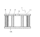
血液処理部1の基本構造は、血液流入口6の周囲を取り囲むように消泡層が配置され、その外側に濾過層が配置される。図1又は図2に示す2は目の粗い消泡層、3は目の細かい消泡層、4は濾過層である。目の粗い消泡層2、目の細かい消泡層3はいずれも中空円柱状である。目の粗い消泡層2と目の細かい消泡層3は、相互に離れて配置されており、両者の間に間隙5Aが形成されている。濾過層4は、複数のひだ(プリーツ)が形成されており、目の細かい消泡層3の外周を被覆するように配置されている。濾過層4のプリーツは、濾過のための表面積を稼ぐとともに、目の細かい除泡層3との間に間隙5Bを形成している。目の粗い消泡層2、目の細かい消泡層3、および濾過層4の上下両端部は、ポリウレタン等の接着剤11によって気密にシールされている。
【0019】
前記目の粗い消泡層2は、孔の開口寸法が300〜1000μm、厚さ5〜15mm程度のものが適当であるが、その材質としては、例えば、発泡ポリウレタン、発泡ポリエチレン、発泡ポリスチレン等の発泡体や、ポリエチレン、ポリエステル、ポリプロピレン等のメッシュ、多孔質セラミック等の焼結体等が挙げられる。より好適には、血液の圧力損失が少なく、且つ血液適合性のある材料を用いるのが好ましい。
【0020】
前記目の細かい消泡層3の材質は、孔の開口寸法が40〜120μm、厚さ1〜10mm程度のものが適当である。その材質、形態としては、前記目の粗い消泡層2と同様のものであっても良いが、好ましくは、消泡層としての機能を有するとともに、プレフィルターとして役割を有する、例えば、織り物状、編み物状(ニット)、不織布状等であるのが好ましい。消泡層の消泡持続性能が優れていても、濾過層4が異物等によって早期に目詰まりすれば、血液処理部の寿命は終わってしまうため、プレフィルターとしての役割をも有する目の細かい消泡層3によって、比較的大きな異物を除去することにより、濾過層4、延いては、血液処理部1の寿命を長くすることができるからである。
【0021】
前記目の粗い消泡層2、および目の細かい消泡層3は消泡剤を担持している。消泡剤は、気泡との表面張力の差により破泡させる機能を有するものであり、例えば、シリコーン等が挙げられる。消泡剤の担持方法は、スプレー塗付、含浸等し、乾燥させることにより行われる。
【0022】
目の粗い消泡層2と目の細かい消泡層3間の間隙5Aは、可能な限り大きいのが好ましいが、後述する実施例中の記載より、3〜50mmであるのが好ましい。50mm以下としたのは、血液処理部1を内蔵する血貯槽が大きくなりすぎない程度の大きさとして適当だからである。
【0023】
また、図1および図2中に記載はないが、間隙5Aに、目の粗い消泡層2と目の細かい消泡層3が内部圧力等によって変形し相互に接触等するのを防止するための位置規制をする部品を設けるのが好ましい。該位置規制をする部品は、例えば、中空円柱状であって、その側壁に、目の粗い消泡層2と目の細かい消泡層3間の血液流路と、目の粗い消泡層2と目の細かい消泡層3間を仕切る隔壁とが交互に形成され、該位置規制をする部品の上下両端が、前記消泡層と濾過層4とともに接着剤11によって気密にシールされるものが挙げられる。
【0024】
前記濾過層4は、孔の開口寸法が20〜40μmのものが好ましく、その材質、形態としては、例えば、ポリエチレン、ポリエステル、ポリプロピレン製の不織布、スクリーンメッシュ等が挙げられる。
【0025】
尚、上記目の粗い消泡層2、目の細かい消泡層3、濾過層4について共通して使用する「孔の開口寸法」とは、孔の最長孔径のことを意味する。
【0026】
図3は、本発明の一実施態様にかかる血貯槽の血液処理部1の使用初期を説明する図である。気泡や異物等が混入した血液は、血液流入口6を通って、目の粗い消泡層の内腔21に入る。血液中に混入した気泡は、浮力により血液の液面上部に集まる。目の粗い消泡層2の孔を通過できない程度の大きな気泡は、消泡剤が塗付等された目の粗い消泡層2の表面に接触して破泡され、該気泡の気体は、目の粗い消泡層の浸潤高さより上部2a、間隙5A、目の細かい消泡層3の浸潤高さより上部3aを経て、濾過層4の浸潤高さより上部4aを通過し、血液処理部外へ流出する。
【0027】
目の粗い消泡層2の孔より小さな気泡は血液とともに目の粗い消泡層2を通過し、間隙5Aに一時貯留され、浮力により血液の液面上部に集められる。該小さな気泡は、目の細かい消泡層3の表面に順次接触して、気泡は破泡され、液体から分離された気体は、細かい目の消泡層3の浸潤高さより上部3a、濾過層4の浸潤高さより上部4aを通過し、血液処理部外へ流出する。以上のようにして、目の粗い消泡層2および目の細かい消泡層3によって、ほとんどすべての気泡が液体から分離されて消泡が行われる。
【0028】
血液中の異物の濾過は、濾過層4によって行われるが、異物の大きさによっては、目の粗い消泡層2、目の細かい消泡層3でも濾過される。
【0029】
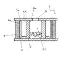
図4は、本発明の一実施態様にかかる貯血槽の血液処理部1の使用中期を説明する図である。目の粗い消泡層2の浸潤高さは、流入時に血液中に混入していた気泡と、目の粗い消泡層内腔21へ落下する時に泡立ち生じる気泡によって、また、目の粗い消泡層を通過できない大きな異物が、目の粗い消泡層2の目を塞ぎ部分的に目づまりを生じるため、経時的に上昇している。目の細かい消泡層3の浸潤高さも経時的に上昇するが、目の粗い消泡層2と目の細かい消泡層3の間に適当な間隙5Aを設けたので、目の粗い消泡層2を通過した血液は一旦間隙5Aに溜まる。したがって、目の細かい消泡層3の浸潤の進行を遅らせることができる。また、間隙5Aに溜まった血中の気泡は、間隙5Aに滞留している間に浮力により上昇し液体と分離され、液面で順次目の細かい消泡層3に接触して破泡されるので、効率的に破泡を行なうことができるとともに、結果、よりいっそう目の細かい消泡層3の浸潤の進行を遅らせることができる。至って、血液から分離された気泡の気体が、消泡層外へ流出するために必要な浸潤されていない箇所が、従来に比べて、広く、長い時間確保されることから、消泡持続性能を高くすることができる。
【0030】
また、消泡部で分離された気泡の気体は、濾過層の浸潤していない部分を通過して血液処理部外へ流出するが、濾過層は消泡剤を担持していないため、目の細かい消泡層を通過した微小気泡が多いと、液体と分離された液面に集められた気泡により濾過層の浸潤が急速に進行する。また分離されない気泡によって濾過層が目詰まりを生じる。至って、濾過層4に気体の流出口が無くなるとともに血液処理部1の内部圧力の上昇により血球が破壊され、貯血槽の寿命が終了する。しかしながら、本発明にかかる貯血槽の血液処理部によれば、上述のとおり、気泡は目の細かい消泡層3によってより効率的且つ確実に除去されることから、目の細かい消泡層を通過する微小気泡の量も少なく、よって濾過層の浸潤の進行の程度も低減され、より長寿命の貯血槽を提供することができる。
【0031】
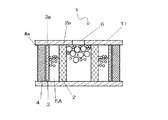
図5は、本発明の一実施態様にかかる貯血槽の血液処理部の使用後期を説明する図である。上述のことにより、目の粗い消泡層2の浸潤がさらに進行し、目の粗い消泡層2の内腔2aの血液流入側内面が、血液と泡によりほぼ全部浸潤された場合、破泡により一旦液体から分離された気体や気泡中の気体は、目の粗い消泡層2の血液流入側内面に気体が流出できる部分がないため、目の粗い消泡層内腔21内の内部圧力が上昇し、前記気体が目の粗い消泡層2のいずれかの箇所から押し出されて粗い目の消泡層の外側に微細な泡を形成する。
【0032】
一方、間隙5Aの液面は、経時的に高くなってはいるが、目の粗い消泡層2の浸潤高さよりも低く、したがって、目の細かい消泡層3の上部には、浸潤されていない部分3aが残されており、目の細かい消泡層3で破泡された気泡の気体は、細かい目の消泡層3の浸潤高さより上部3aを通過し、濾過層4の浸潤高さより上部4aを経て、血液処理部外へ流出する。
【0033】
図6は、本発明の一実施形態にかかる貯血槽の正面断面図を示す図である。図6に示す7はハウジング本体、8は蓋体、1は血液処理部、9は静脈血濾過部である。
【0034】
ハウジング7は、概ね四角形状のハウジング上部と、該ハウジング上部から徐々に縮径して、その終端に血液流出部73が形成されたハウジング下部とを有する。ハウジング上部には、術野から吸引した心内血を消泡および濾過するための血液処理部1が内蔵されている。ハウジング上部からハウジング下部にかけて、静脈血を濾過するめの静脈血濾過部9が内蔵されている。また、ハウジング下部には、血液処理部1によって消泡および濾過された血液と静脈血濾過部9によって濾過された静脈血を一時貯留するための貯血部が形成されている。
【0035】
蓋体8には、静脈血流入用ポート81、複数個の吸引血(心内血)流入用ポート83が形成されており、ハウジング上部の開口と嵌合により連結されている。静脈血入用ポート81は、蓋体8の上方及び内方の双方に向かってそれぞれ管状体が形成されており、静脈血流入用ポート81の上方から流入する血液が、蓋体8の内方に向かって形成された管状体に接続されハウジング下部の貯血部の下方まで伸びた可撓管10によって導かれて、ハウジング下部に流入されるようになっている。
【0036】
また、蓋体8には、複数の吸引血流入用ポート83から吸引される血液の流路を規制し、血液処理部1に血液をスムーズに導くための隔壁(図示せず)を蓋体8と別体或いは一体的に形成するのが好ましい。また、蓋体8には、血液処理部1で破泡され、血液から分離された気体をハウジング外に排出するための気体流出用ポート、その他、施術中に薬液を投与するための混注用ポートが適宜形成されている。
【0037】
前記吸引血流入用ポート83から吸引された心内血は、血液流入口6から、血液処理部1の目の粗い消泡層内腔21へ流入し、順次、目の粗い消泡層2、間隙5A、目の細かい消泡層3、濾過層4を経て、消泡および濾過され、受け皿13内に流入するようになっている。受け皿13は、前記蓋体8と共同して血液処理部1の中空円筒状上下両端部をシールしている。また、受け皿13の下部には、血液処理部1で消泡および濾過された血液をハウジング下部に流入させるための排出口13aが形成されている。
【0038】
前記静脈血を濾過するための静脈血濾過部9は、概ねハウジングと同様な形態のフレームに、スクリーンフィルターが貼着されて形成されており、前記血液処理部1の外側を被嵌するように配置されている。また、静脈血濾過部9には、前記受け皿13の排出口13aから流出する血液が、落下等により再び気泡を形成することが無いよう、ハウジング下部に向かって緩やかな斜面9aを形成している。血液処理部1で消泡および濾過された心内血は、該斜面9a上を流れて、ハウジング下部に貯留された静脈血と合流する。静脈血濾過部9は、前記静脈血流入用ポート81から流入する静脈血を濾過するとともに、前記受け皿13の排出口13aから流出する血液が、落下等により再び気泡を形成した場合の該気泡を除去する。
【0039】
本実施の形態にかかる貯血槽によれば、内蔵される心内血用血液処理部1が、従来のものに比べて、消泡持続性能に優れるため、長寿命の貯血槽を提供することができる。また、従来、高さ方向に大きい血液処理部を採用することによって長寿命化を図った貯血槽もあったが、該貯血槽は、長寿命化の利益が得られる反面、血液処理部の一部が貯留された血液に漬かるため、消泡剤(シリコーン)の血液中への混入による人体への悪影響、消泡剤の血液中への流出による消泡能の低下の懸念があった。本実施形態にかかる貯血槽によれば、貯血槽に内蔵される血液処理部1が、消泡持続性能に優れると同時に、高さ方向への大きさを小さくすることが可能であるため、貯血槽の最大貯血面(貯血槽に血液が最大量貯留されたときの時の血液の液面)より上に血液処理部を配置することにより、消泡剤(シリコーン)の血液中への混入による人体への悪影響、消泡剤の血液中への流出による消泡能の低下の問題が軽減され、且つ高さ方向への大型化を伴うことのない貯血槽の提供が可能である。
【0040】
【実施例】
目の粗い消泡層2として、内径84mm、高さ40mm、厚さ10mm、孔径(開口寸法)13ppiのポリウレタンフォ−ムを、目の細かい消泡層3として、内径124mm、高さ40mm、厚さ2mm、孔径120μmのポリエステルニットを、同心円状に配置し、これら上下をウレタンによりポッティングした血液処理部1(試料1〜6)について、図7に示す実験回路により、消泡持続性能評価試験を行なった。図7中の1は血液処理部、13はポンプである。血液は、ヘマトクリット値35%(25℃)のクエン酸牛血を使用した。
【0041】
消泡持続性能評価試験は、試料1〜6について、それぞれ血液流入口6に血液流量5(l/min)の血液を供給するとともに、この血液に1(l/min)の割合で気泡を混入させ、ポリエステルニットの全面が浸潤し気泡がポリエステルニットの外側に漏出するまでの時間を測定した。通常、血液処理部1には、2l/min程度の血液流量の血液が流入されるが、術野に大量出血があった時には、短時間ではあるが5l/min程度の血液流量で血液が流入されることがあるため、過酷な条件として、血液流量が5l/minの場合の、目標の消泡持続時間を約10分に設定した。
【0042】
【表1】

表1に示すように、目の粗い消泡層2(ポリウレタンフォ−ム)と目の細かい消泡層3(ポリエステルニット)の間に間隙が全く無い場合に比べて、間隙を設けたものは、その間隙が大きくなるにつれて消泡持続時間が長くなっており、間隙が3mm以上のものは、目標の消泡持続能を有していた。
【0044】
【発明の効果】
上記のとおり、本発明にかかる貯血槽は、目の粗い消泡層を通過した血液を、該血中の気泡が浮力により上昇し液体と分離されるまでに必要且つ十分な時間、間隙に滞留させることができ、浮力により上昇し液面に集められた気泡を、目の細かい消泡層に順次接触して効率的に破泡することができる。
【0045】
また、本発明にかかる貯血槽は、目の粗い消泡層と目の細かい消泡層を離して配置したこと、および上述のとおり効率的に消泡を行なうことができることから、目の細かい消泡層の浸潤の進行を遅らせることができる。したがって、血液から分離された気泡の気体が消泡層外へ流出するために必要な浸潤されていない箇所が、従来に比べて、広く且つ長い時間確保することができることから、消泡持続性能を高くすることができる。
【0046】
また、本発明にかかる貯血槽は、前記浮力により上昇した気泡を、目の細かい消泡層に到達するまでの間に、より大きな気泡に成長させ、該気泡を消泡することから、より確実に消泡を行なうことができる。
【0047】
また、本発明にかかる貯血槽は、貯血槽の血液処理部が消泡層の外側にさらに濾過層を備えるものである場合において、上述のとおり、気泡が目の細かい消泡層によって効率的且つ確実に除去されることから、目の細かい消泡層を通過する微小気泡による濾過層の浸潤の進行の程度が低減され、至って、より長寿命の貯血槽を提供することができる。
【0048】
また、貯血槽に内蔵される血液処理部1が、消泡持続性能に優れると同時に、高さ方向への大きさを小さくすることが可能であるため、貯血槽の最大貯血面より上に血液処理部を配置することにより、消泡剤(シリコーン)の血液中への混入による人体への悪影響、消泡剤の血液中への流出による消泡能の低下の問題が軽減され、且つ高さ方向への大型化を伴うことのない貯血槽の提供ができる。
【0049】
【図面の簡単な説明】
【図1】本発明の一実施形態にかかる貯血槽の血液処理部の正面断面図である。
【図2】本発明の一実施形態にかかる貯血槽の血液処理部の平面断面図である。
【図3】本発明の一実施態様にかかる貯血槽の血液処理部の使用初期を説明する図である。
【図4】本発明の一実施態様にかかる貯血槽の血液処理部の使用中期を説明する図である。
【図5】本発明の一実施態様にかかる貯血槽の血液処理部の使用後期を説明する図である。
【図6】本発明の一実施形態にかかる貯血槽の正面断面図である。
【図7】消泡持続性能評価試験の実験回路図である。
【符号の説明】
1 血液処理部
2 目の粗い消泡層
2a 目の粗い消泡層の浸潤高さより上部
21 目の粗い消泡層内腔
3 目の細かい消泡層
3a 目の細かい消泡層の浸潤高さより上部
4 濾過層
4a 濾過層の浸潤高さより上部
5A 間隙
5B 間隙
6 血液流入口
7 ハウジング本体
73 血液流出部
8 蓋体
81 静脈血流入用ポート
83 吸引血流入用ポート
9 静脈血濾過部
9a 緩やかな斜面
10 可撓管
13 受け皿
13a 排出口[0001]
BACKGROUND OF THE INVENTION
The present invention relates to a blood reservoir that is installed in an extracorporeal circuit and removes bubbles and the like in blood, and more particularly to a blood reservoir that is particularly excellent in defoaming performance.
[0002]
[Prior art]
When performing cardiac surgery, extracorporeal circulation using an artificial lung extracorporeal blood circuit is performed as an alternative to the function of the heart and lungs during that time. In this blood circuit, an artificial lung for adding oxygen to venous blood removed from the patient's veins, a blood reservoir for primary storage of blood removed from the veins (called `` venous blood reservoir '') ) Is provided. In addition, a blood reservoir (referred to as “intracardiac blood reservoir”) for collecting and temporarily storing blood overflowing in the heart chamber is integrated with the venous blood reservoir (“intracardiac blood reservoir integrated type”). Called “Venous Blood Reservoir” or separately. The intracardiac blood reservoir is not only a reservoir for temporarily storing blood, but also an antifoaming part for defoaming blood sucked from the surgical field of extracorporeal circulation and foreign substances (fine particles, meat pieces, fat, It has a blood processing part composed of a filtration part for filtering blood clots and the like, and the blood prepared in these blood reservoirs is returned to the circuit to make extracorporeal circulation safer.
[0003]
The antifoaming part used in the venous blood reservoir, intracardiac blood reservoir, and intracardiac blood reservoir-integrated venous blood reservoir is generally a urethane carrying a defoamer such as silicone on its surface. A reticulated porous sponge such as foam is used, and when blood passes through the defoaming part, a structure in which bubbles mixed in the blood are brought into contact with the defoaming agent and broken is known. . In addition, with regard to the defoaming portion, various configurations have been disclosed in order to prevent the destruction of blood due to the passage of microbubbles and the increase in pressure during passage of blood. As an example, JP-A-2-60657 is disclosed. Some are described in the publication.
[0004]
In the blood reservoir described in the publication, a defoaming material and a defoamer composed of a mesh-like three-dimensional cube (foam) and a mesh body having an opening of 50 to 300 mesh provided close to the downstream side thereof. The material is used, and relatively large bubbles can be removed by foaming, and microbubbles that have passed through the foam can be removed by reticulation, so that blood with bubbles remaining is returned to the patient. It is stated that there is no such thing. If different mesh openings are used at the top and bottom of the mesh body, the microbubbles are mainly removed by the mesh body with fine mesh openings, and the pressure loss during the passage of blood is increased by the mesh body with coarse mesh openings. It is described that even if the mesh with fine openings is clogged with microbubbles or foreign matter, blood will not flow and the flow of blood will not stop even if the mesh with fine openings is clogged with foreign matter, etc. Has been.
[0005]
By the way, in the case of a blood reservoir (generally referred to as “closed type”) in which the defoaming part or the upper and lower parts of the blood treatment part composed of the defoaming part and the filtration part are sealed with an adhesive such as urethane is generally used. The bubble gas broken by the foam part passes through the defoamed part, the defoamed part, and the part not infiltrated by the blood of the filter part, and flows out to the outside. When blood is completely infiltrated in any one of the defoaming part and the filtering part, there is no bubble gas outlet, the gas cannot be discharged to the outside, and the life of the blood reservoir is terminated. That is, the progress of infiltration of the defoaming part or the filtration part is one of the factors that determine the life of the blood reservoir.
[0006]
[Problems to be solved by the invention]
When the one described in the above publication is used in the closed mold, (1) since the foam and the mesh body are close to each other, when the foam infiltrates, the mesh body also infiltrates the foam immediately. It will infiltrate to the same height as the part. Therefore, there is a problem that the gas outlet is narrowed quickly, and the life of the blood reservoir is quickly terminated. (2) Further, since the foam and the mesh body are close to each other, the time until the blood bubbles that have passed through the foam are separated from the liquid by buoyancy is short, and the air bubbles have rough openings at the bottom of the mesh body. There is a risk that blood that passes through the reticulate and remains air bubbles may be returned to the patient. (3) Furthermore, since the bubbles are removed by the mesh without sufficiently separating the bubbles and the liquid, the bubble removal efficiency is not good. These are more prominent problems when used for the defoaming of intracardiac blood, in which the foaming of blood is intense and clogging of the defoamed portion due to foreign substances is likely to occur.
[0007]
Even with intracardiac blood reservoirs with relatively high defoaming performance currently available on the market, depending on the type of surgery, the defoaming section May infiltrate and stop functioning. Assuming such a situation, the circuit is provided with a port for connecting a replacement intracardiac blood reservoir in advance, and a new intracardiac blood reservoir is connected to the port to continue the operation. There is also an example, and there is a demand for providing a blood storage tank having better antifoaming performance.
[0008]
Therefore, an object of the present invention is to provide a blood reservoir that is more excellent in antifoaming performance.
[0009]
[Means for Solving the Problems]
In order to solve the above-described problems, a blood reservoir according to the present invention is a blood reservoir having at least a defoaming portion for removing bubbles from blood in a housing having a blood inlet and a blood outlet, and the defoaming portion is an eye. And a fine defoaming layer closer to the blood flow inlet, and a fine defoaming layer distal to the blood inlet. The blood is temporarily stored between the coarse defoaming layer and the fine defoaming layer, and the air bubbles that have passed through the coarse defoaming layer together with the blood are removed from the stored blood. A gap that can be collected at the upper part of the liquid surface is provided, the coarse antifoaming layer and the fine antifoaming layer are formed in a cylindrical shape, and the gap is provided between both layers, The gap provided between the two layers is 3 to 50 mm. In the gap, an obstacle that prevents the bubbles from rising when the bubbles mixed in the blood stored in the gap passing through the coarse defoaming layer rise to the blood surface side by buoyancy. There is no It is characterized by this.
[0010]
By adopting such a configuration, the blood that has passed through the coarse defoaming layer can be retained in the gap for a necessary and sufficient time until the bubbles in the blood rise due to buoyancy and are separated from the liquid, The bubbles that have risen due to the buoyancy are collected on the liquid surface and sequentially contacted with the fine defoaming layer to be broken, so that defoaming can be performed efficiently.
[0011]
Further, the blood reservoir according to the present invention has a fine defoaming layer and a fine defoaming layer that are arranged apart from each other, and the defoaming can be efficiently performed as described above. The progress of infiltration of the foam layer can be delayed. Therefore, the non-infiltrated part necessary for the gas of bubbles separated from the blood to flow out of the defoaming layer can be secured widely and for a long time compared to the conventional case, so that the defoaming performance is improved. Can be high.
[0012]
In addition, the blood reservoir according to the present invention grows bubbles that have risen due to the buoyancy into larger bubbles before reaching the fine defoaming layer, and defoams the bubbles. It is possible to defoam bubbles.
[0013]
In addition, the blood reservoir according to the present invention can also delay the progress of infiltration of the filtration layer when the blood treatment part of the blood reservoir is further provided with a filtration layer outside the antifoaming layer. When the filtration layer is completely infiltrated, there is no gas outlet and the life of the blood reservoir ends, but according to the blood reservoir according to the present invention, bubbles are more efficiently and reliably removed by the fine defoaming layer. Therefore, the progress of the infiltration of the filtration layer due to the fine bubbles passing through the fine defoaming layer is reduced, and a long-life blood reservoir can be provided.
[0014]
The “infiltration” used in the blood reservoir according to the present invention means a state in which the surface of the defoaming layer or the filtration layer is covered with liquid and bubbled blood. The “infiltration height” means the height up to the infiltrated portion where the gas cannot pass through the defoaming layer or the filtration layer.
[0015]
The “coarse” and “fine” eyes used in the blood reservoir according to the present invention are used in a relative meaning with respect to the two antifoam layers, and the specific degree thereof will be described later.
[0016]
DETAILED DESCRIPTION OF THE INVENTION
Hereinafter, a blood reservoir according to an embodiment of the present invention will be described with reference to FIGS.
[0017]
FIG.1 and FIG.2 is a conceptual diagram explaining the defoaming principle of the
[0018]
In the basic structure of the
[0019]
The
[0020]
The
[0021]
The
[0022]
The
[0023]
Although not shown in FIG. 1 and FIG. 2, in order to prevent the
[0024]
The
[0025]
In addition, the "opening dimension of a hole" used in common about the said
[0026]
FIG. 3 is a view for explaining the initial use of the
[0027]
Bubbles smaller than the pores of the
[0028]
The filtration of foreign matter in blood is performed by the
[0029]
FIG. 4 is a diagram for explaining a mid-use period of the
[0030]
In addition, the bubble gas separated in the defoaming part flows out of the blood treatment part through the non-infiltrated part of the filtration layer, but the filtration layer does not carry an antifoaming agent. When there are many micro bubbles that have passed through the fine defoaming layer, the infiltration of the filtration layer proceeds rapidly due to the bubbles collected on the liquid surface separated from the liquid. In addition, the filtration layer is clogged by the bubbles that are not separated. As a result, there is no gas outlet in the
[0031]
FIG. 5 is a diagram for explaining a later stage of use of the blood processing unit of the blood reservoir according to one embodiment of the present invention. By the above, infiltration of the
[0032]
On the other hand, the liquid level of the
[0033]
FIG. 6 is a front sectional view of the blood reservoir according to one embodiment of the present invention. In FIG. 6, 7 is a housing body, 8 is a lid, 1 is a blood treatment unit, and 9 is a venous blood filtration unit.
[0034]
The
[0035]
The lid body 8 is formed with a venous blood
[0036]
Further, the lid body 8 is provided with a partition wall (not shown) for restricting the flow paths of the blood sucked from the plurality of suction
[0037]
The intracardiac blood sucked from the suction
[0038]
The venous
[0039]
According to the blood reservoir according to the present embodiment, the built-in
[0040]
【Example】
The
[0041]
In the defoaming continuous performance evaluation test, blood of a blood flow rate of 5 (l / min) is supplied to the
[0042]
[Table 1]
As shown in Table 1, compared to the case where there is no gap between the coarse defoaming layer 2 (polyurethane foam) and the fine defoaming layer 3 (polyester knit), the one provided with a gap is The defoaming duration was longer as the gap was larger, and those with a gap of 3 mm or more had the target defoaming ability.
[0044]
【The invention's effect】
As described above, the blood reservoir according to the present invention retains the blood that has passed through the coarse defoaming layer in the gap for a sufficient and sufficient time until the bubbles in the blood rise due to buoyancy and are separated from the liquid. The bubbles rising due to the buoyancy and collected on the liquid surface can be brought into efficient contact with the fine defoaming layer in order to break the bubbles efficiently.
[0045]
Further, the blood reservoir according to the present invention has a fine defoaming layer and a fine defoaming layer that are arranged apart from each other, and the defoaming can be efficiently performed as described above. The progress of infiltration of the foam layer can be delayed. Therefore, the non-infiltrated part necessary for the gas of bubbles separated from the blood to flow out of the defoaming layer can be secured widely and for a long time compared to the conventional case, so that the defoaming performance is improved. Can be high.
[0046]
In addition, the blood reservoir according to the present invention grows bubbles that have risen due to the buoyancy into larger bubbles before reaching the fine defoaming layer, and defoams the bubbles. Can be defoamed.
[0047]
Further, in the blood reservoir according to the present invention, in the case where the blood treatment part of the blood reservoir is further provided with a filtration layer outside the antifoaming layer, as described above, the bubbles are efficiently and finely removed by the fine antifoaming layer. Since it is reliably removed, the degree of progress of infiltration of the filtration layer by the fine bubbles passing through the fine defoaming layer is reduced, and a long-life blood reservoir can be provided.
[0048]
In addition, since the
[0049]
[Brief description of the drawings]
FIG. 1 is a front sectional view of a blood processing unit of a blood reservoir according to an embodiment of the present invention.
FIG. 2 is a plan cross-sectional view of a blood processing unit of a blood reservoir according to an embodiment of the present invention.
FIG. 3 is a view for explaining the initial use of the blood processing section of the blood reservoir according to one embodiment of the present invention.
FIG. 4 is a diagram for explaining a middle period of use of the blood processing unit of the blood reservoir according to one embodiment of the present invention.
FIG. 5 is a diagram for explaining a later stage of use of the blood processing unit of the blood reservoir according to one embodiment of the present invention.
FIG. 6 is a front sectional view of a blood reservoir according to one embodiment of the present invention.
FIG. 7 is an experimental circuit diagram of a defoaming continuous performance evaluation test.
[Explanation of symbols]
1 Blood processing department
2 Rough defoaming layer
2a Above the infiltration height of the coarse defoaming layer
21 Antifoam layer lumen with a coarse eye
3 Fine antifoam layer
3a Above the infiltration height of the fine defoaming layer
4 Filtration layer
4a Above the infiltration height of the filtration layer
5A gap
5B gap
6 Blood inlet
7 Housing body
73 Blood outflow part
8 Lid
81 Port for venous blood flow
83 Port for suction blood flow
9 Venous blood filtration unit
9a A gentle slope
10 Flexible tube
13 saucer
13a outlet
Claims (4)
Priority Applications (1)
| Application Number | Priority Date | Filing Date | Title |
|---|---|---|---|
| JP2000021885A JP4332969B2 (en) | 2000-01-31 | 2000-01-31 | Blood reservoir |
Applications Claiming Priority (1)
| Application Number | Priority Date | Filing Date | Title |
|---|---|---|---|
| JP2000021885A JP4332969B2 (en) | 2000-01-31 | 2000-01-31 | Blood reservoir |
Publications (2)
| Publication Number | Publication Date |
|---|---|
| JP2001204815A JP2001204815A (en) | 2001-07-31 |
| JP4332969B2 true JP4332969B2 (en) | 2009-09-16 |
Family
ID=18548240
Family Applications (1)
| Application Number | Title | Priority Date | Filing Date |
|---|---|---|---|
| JP2000021885A Expired - Fee Related JP4332969B2 (en) | 2000-01-31 | 2000-01-31 | Blood reservoir |
Country Status (1)
| Country | Link |
|---|---|
| JP (1) | JP4332969B2 (en) |
Families Citing this family (5)
| Publication number | Priority date | Publication date | Assignee | Title |
|---|---|---|---|---|
| JP4867692B2 (en) * | 2007-02-15 | 2012-02-01 | 株式会社ジェイ・エム・エス | Cardiotomy filter and blood reservoir |
| DE102009026592B4 (en) | 2009-05-29 | 2014-08-28 | Sorin Group Deutschland Gmbh | Device for determining the venous inflow to a blood reservoir of an extracorporeal blood circulation |
| DE102009027195A1 (en) | 2009-06-25 | 2010-12-30 | Sorin Group Deutschland Gmbh | Device for pumping blood in an extracorporeal circuit |
| EP2754458B1 (en) | 2011-07-12 | 2017-02-01 | Sorin Group Italia S.r.l. | Dual chamber blood reservoir |
| WO2015173611A1 (en) | 2014-05-16 | 2015-11-19 | Sorin Group Italia S.R.L. | Blood reservoir with fluid volume measurement based on pressure sensor |
-
2000
- 2000-01-31 JP JP2000021885A patent/JP4332969B2/en not_active Expired - Fee Related
Also Published As
| Publication number | Publication date |
|---|---|
| JP2001204815A (en) | 2001-07-31 |
Similar Documents
| Publication | Publication Date | Title |
|---|---|---|
| US6908446B2 (en) | Blood reservoir | |
| US4743371A (en) | Blood filter | |
| US7621407B2 (en) | Extracorporeal blood filter system | |
| EP0122748B1 (en) | Blood filter | |
| WO2010041604A1 (en) | Blood storage tank | |
| JPH0126704B2 (en) | ||
| JP4164770B2 (en) | Blood filter device and manufacturing method thereof | |
| JP4332969B2 (en) | Blood reservoir | |
| JP2002165878A (en) | Blood storage tank | |
| JP3231077B2 (en) | Blood reservoir | |
| JP5293066B2 (en) | Filter member, blood reservoir | |
| JP4952232B2 (en) | Blood reservoir | |
| JP2007190372A (en) | Blood processing filter apparatus | |
| JP4132777B2 (en) | Artificial lung blood reservoir | |
| JP4485707B2 (en) | Blood reservoir | |
| JPH0126707B2 (en) | ||
| JP3373252B2 (en) | Blood reservoir | |
| JP4162315B2 (en) | Blood reservoir | |
| JPS63102764A (en) | Blood storage tank | |
| JP3373250B2 (en) | Blood reservoir | |
| JPH02124170A (en) | Blood storage vessel | |
| JPS6145770A (en) | Blood storage tank | |
| JPH0117383B2 (en) | ||
| JP3270193B2 (en) | Filtration device | |
| JP2002204827A (en) | Venous blood storage tub with cardiotomy |
Legal Events
| Date | Code | Title | Description |
|---|---|---|---|
| A621 | Written request for application examination |
Free format text: JAPANESE INTERMEDIATE CODE: A621 Effective date: 20070116 |
|
| A977 | Report on retrieval |
Free format text: JAPANESE INTERMEDIATE CODE: A971007 Effective date: 20080922 |
|
| A131 | Notification of reasons for refusal |
Free format text: JAPANESE INTERMEDIATE CODE: A131 Effective date: 20081003 |
|
| A521 | Written amendment |
Free format text: JAPANESE INTERMEDIATE CODE: A523 Effective date: 20081126 |
|
| A02 | Decision of refusal |
Free format text: JAPANESE INTERMEDIATE CODE: A02 Effective date: 20081225 |
|
| A521 | Written amendment |
Free format text: JAPANESE INTERMEDIATE CODE: A523 Effective date: 20090212 |
|
| A911 | Transfer of reconsideration by examiner before appeal (zenchi) |
Free format text: JAPANESE INTERMEDIATE CODE: A911 Effective date: 20090303 |
|
| A131 | Notification of reasons for refusal |
Free format text: JAPANESE INTERMEDIATE CODE: A131 Effective date: 20090407 |
|
| A521 | Written amendment |
Free format text: JAPANESE INTERMEDIATE CODE: A523 Effective date: 20090408 |
|
| TRDD | Decision of grant or rejection written | ||
| A01 | Written decision to grant a patent or to grant a registration (utility model) |
Free format text: JAPANESE INTERMEDIATE CODE: A01 Effective date: 20090602 |
|
| A01 | Written decision to grant a patent or to grant a registration (utility model) |
Free format text: JAPANESE INTERMEDIATE CODE: A01 |
|
| A61 | First payment of annual fees (during grant procedure) |
Free format text: JAPANESE INTERMEDIATE CODE: A61 Effective date: 20090615 |
|
| FPAY | Renewal fee payment (event date is renewal date of database) |
Free format text: PAYMENT UNTIL: 20120703 Year of fee payment: 3 |
|
| R150 | Certificate of patent or registration of utility model |
Free format text: JAPANESE INTERMEDIATE CODE: R150 |
|
| FPAY | Renewal fee payment (event date is renewal date of database) |
Free format text: PAYMENT UNTIL: 20130703 Year of fee payment: 4 |
|
| R250 | Receipt of annual fees |
Free format text: JAPANESE INTERMEDIATE CODE: R250 |
|
| R250 | Receipt of annual fees |
Free format text: JAPANESE INTERMEDIATE CODE: R250 |
|
| R250 | Receipt of annual fees |
Free format text: JAPANESE INTERMEDIATE CODE: R250 |
|
| LAPS | Cancellation because of no payment of annual fees |