EP1115022A2 - Optoelektronische Abtastvorrichtung - Google Patents
Optoelektronische Abtastvorrichtung Download PDFInfo
- Publication number
- EP1115022A2 EP1115022A2 EP00103837A EP00103837A EP1115022A2 EP 1115022 A2 EP1115022 A2 EP 1115022A2 EP 00103837 A EP00103837 A EP 00103837A EP 00103837 A EP00103837 A EP 00103837A EP 1115022 A2 EP1115022 A2 EP 1115022A2
- Authority
- EP
- European Patent Office
- Prior art keywords
- optoelectronic device
- polygon mirror
- coil
- mirror wheel
- magnet
- Prior art date
- Legal status (The legal status is an assumption and is not a legal conclusion. Google has not performed a legal analysis and makes no representation as to the accuracy of the status listed.)
- Granted
Links
Images

Classifications
-
- G—PHYSICS
- G06—COMPUTING; CALCULATING OR COUNTING
- G06K—GRAPHICAL DATA READING; PRESENTATION OF DATA; RECORD CARRIERS; HANDLING RECORD CARRIERS
- G06K7/00—Methods or arrangements for sensing record carriers, e.g. for reading patterns
- G06K7/10—Methods or arrangements for sensing record carriers, e.g. for reading patterns by electromagnetic radiation, e.g. optical sensing; by corpuscular radiation
- G06K7/10544—Methods or arrangements for sensing record carriers, e.g. for reading patterns by electromagnetic radiation, e.g. optical sensing; by corpuscular radiation by scanning of the records by radiation in the optical part of the electromagnetic spectrum
- G06K7/10554—Moving beam scanning
- G06K7/10594—Beam path
- G06K7/10603—Basic scanning using moving elements
- G06K7/10613—Basic scanning using moving elements by rotation, e.g. polygon
-
- G—PHYSICS
- G02—OPTICS
- G02B—OPTICAL ELEMENTS, SYSTEMS OR APPARATUS
- G02B26/00—Optical devices or arrangements for the control of light using movable or deformable optical elements
- G02B26/08—Optical devices or arrangements for the control of light using movable or deformable optical elements for controlling the direction of light
- G02B26/10—Scanning systems
- G02B26/12—Scanning systems using multifaceted mirrors
- G02B26/121—Mechanical drive devices for polygonal mirrors
- G02B26/122—Control of the scanning speed of the polygonal mirror
Definitions
- the invention relates to an optoelectronic device according to the preamble of claim 1.
- Such optoelectronic devices are used to detect marks used, which have defined contrast patterns.
- the optoelectronic device as a barcode reader for reading barcodes be trained.
- the optoelectronic device has a light beam emitting Transmitter and a receiver receiving receiving light rays. There is also a deflection unit with a motor-driven polygon mirror wheel intended. The transmitted light rays and the received light rays are guided over the polygon mirror. By rotating the polygon mirror wheel the transmitted light beams are deflected so that they are periodic paint over an area in which the marks are located.
- the transmitted light beams are over the marks guided. According to the contrast pattern of the brands they point to them received light beams reflect an amplitude modulation.
- the appropriately modulated receive signals at the output of the receiver evaluated in an evaluation unit for the detection of the marks.
- the polygon mirror wheel is driven by a motor, so that the polygon mirror wheel rotates at a predetermined speed.
- motors are usually used for this purpose, in which an engine control is integrated.
- the motor also has a shaft. On the shaft is applied with a mechanical mount on its top the polygon mirror wheel is attached.
- the polygon mirror wheel preferably has For this purpose, a holder on which the receptacle is screwed.
- the motor controller is connected to the evaluation unit via a cable is arranged on a separate circuit board. To contact is at the end of the cable, a connector is provided which in a corresponding socket on the Evaluation unit is inserted.
- deflection unit designed in this way has a large number of electrical and mechanical components.
- the assembly of these components is time consuming and thus represents an undesirably high Cost factor in the manufacture of the optoelectronic device.
- the tolerances of the individually manufactured components mean that Accuracy problems occur with deflection units produced in this way.
- deflection units designed in this way are undesirable large size.
- the invention has for its object a deflection unit for an optoelectronic To create device of the type mentioned, which if possible low manufacturing costs and low manufacturing tolerances has small size.
- the evaluation unit is in the optoelectronic device according to the invention integrated on a printed circuit board, the motor driving the polygon mirror wheel has a shaft opening out on this circuit board which the polygon mirror wheel is rotatably mounted.
- the engine a coil that sits on the circuit board and is connected to it.
- This coil works with one attached to the inside of the polygon mirror wheel Magnets together.
- a major advantage here is that the shaft and the coil of the Motors are attached directly to the circuit board on which the evaluation unit is integrated.
- the motor, in particular the coil, is activated therefore directly via the evaluation unit.
- this can considerably reduce the space required for the deflection unit become. Due to the deflection unit designed in this way, the Size of the entire optoelectronic device can be reduced. In addition, this will also result in a significant reduction in manufacturing costs Device reached.
- the deflection unit has only a small number of Has individual components.
- the manufacturing tolerances in the manufacture of the The deflection unit is accordingly small.
- the deflection unit can be installed quickly and easily.
- the brand 1 shows the basic structure of an optoelectronic device 1 for recognizing marks provided with defined contrast patterns.
- the brands can have any sequence and form of each other adjacent light-dark areas, preferably black and white areas, exhibit.
- the brands of Barcodes 2 formed.
- the barcodes 2 essentially consist of a sequence of black and white line elements 2a, 2b of defined length and width.
- the optoelectronic device 1 is then designed as a barcode reader.
- the optoelectronic device 1 has a transmitting element 3, a receiving element 4 and an evaluation unit 5.
- the transmission element 3 consists of a transmitter 6, preferably a laser diode, and one of the transmitters 6 upstream transmission optics 7 for focusing the transmitted light beams 8. Die focused transmitted light beams 8 are via a rotating polygon mirror wheel 9 deflected and passed over the barcode symbol 2 to be detected.
- the axis of rotation of the polygon mirror wheel 9 is perpendicular to that shown in FIG Equatorial plane of the polygon mirror 9 arranged.
- the transmitted light beams 8 are periodically inside a predetermined angular range within that forming the scanning plane Equatorial level led. You can do this according to the focus of the transmitted light beams 8 bar codes 2 in a predetermined distance range to be read.
- the received light beams 10 reflected by the bar code 2 are transmitted via the Polygon mirror 9 led to the receiving element 4.
- the receiving element 4 consists of a receiver 11, which is formed by a photodiode and in which the received light beams 10 converted into an electrical received signal become.
- An amplifier 12 is connected downstream of the receiver 11.
- the receiving element 4 is receiving optics 13 upstream.
- the received signal at the output of the receiving element 4 becomes supplied to the evaluation unit 5.
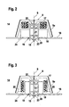
- FIGS. 2 and 3 show two exemplary embodiments of a deflection unit 14, the component of which is the polygon mirror wheel 9 according to FIG. 1. Also includes the deflection unit 14 is a motor by means of which the polygon mirror wheel 9 is driven is so that it rotates at a predetermined speed executes.
- This motor comprises a shaft 15 on which the polygon mirror wheel 9 is rotatably mounted, as well as a coil 16 and one interacting with it Magnet 17.
- the shaft 15 opens out on a circuit board 18 on which the evaluation unit 5 is integrated.
- the longitudinal axis of the shaft 15 is perpendicular to the surface of the circuit board 18.
- the coil 16 is seated on this circuit board 18 on.
- the magnet 17 is attached to the polygon mirror wheel 9 and rotates with it this with.
- a current is fed into the coil 16 via the evaluation unit 5, whereby a magnetic field is generated in the coil 16, through which the magnet 17 and thus the polygon mirror 9 is rotated becomes.
- the electronic components of the evaluation unit are on the printed circuit board 18 5 arranged, these for the sake of clarity in Figures 2 and 3 are not shown.
- a bore 19 is in the center of the printed circuit board 18 intended.
- a tube 20 is mounted, which is from the circuit board 18 protrudes vertically.
- the tube 20 consists of a hollow cylindrical Plastic part, the top and bottom of which are open. Alternatively the tube 20 can consist of metal.
- the shaft 15 runs inside the tube 20, the shaft 15 via bearings 21 is mounted on the inner wall of the tube 20.
- the shaft 15 runs in the longitudinal direction of the tube 20 along its axis of symmetry S.
- the bearings 21 can in particular be designed as a ball bearing, plain bearing or roller bearing.
- the Shaft 15 rotates according to the speed specified above the motor around the axis of symmetry S and the polygon mirror wheel attached to it 9 in a corresponding rotary movement.
- the polygon mirror 9 is in the illustrated embodiments of a molded plastic part.
- This polygon mirror wheel 9 is inclined side walls tapering to a flat ceiling.
- the outside of the side walls of the polygon mirror wheel 9 are coated with a reflective layer and form the mirror surfaces 9a on which the transmitted light beams 8 to get distracted.
- the ceiling and the side walls delimit a cavity inside the polygon mirror wheel 9, which is open at the bottom.
- the tube 20 with the shaft 15 supported therein projects from the underside into the cavity of the polygon mirror wheel 9.
- the shaft 15 protrudes over the upper end of the tube 20.
- the upper free end of the shaft 15 is with the ceiling of the polygon mirror 9th rigidly connected.
- the ceiling of the polygon mirror wheel 9 is in its center widened towards the bottom. In this broadening there is one in the symmetry axis S of the polygon mirror wheel 9 extending and at the bottom of the Cover opening 22 provided in the free end of the shaft 15 is pressed.
- the shaft can also be designed as an insert, which at the production of the molded plastic part is encapsulated with plastic.
- the shaft 15 is fixed with a clamp closure 23.
- the polygon mirror wheel 9 is thus symmetrical to that of the axis of symmetry S formed axis of rotation, in which the shaft 15 is arranged, wherein the side walls of the polygon mirror wheel 9 at a predetermined distance from the tube 20 run.
- the overall heights of the shaft 15 and the tube 20 are based on the overall height of the polygon mirror wheel 9 adjusted so that the lower edges of the side walls of the Polygon mirror 9 run closely above the circuit board 18. It is however, the distance chosen is so large that it rotates when the polygon mirror 9 not arranged for contact with the printed circuit board 18 or thereon Components is coming.
- the coil 16 lies against the outside of the tube 20.
- the coil 16 is there arranged rotationally symmetrical to the axis of rotation of the shaft 15 and sits on a not shown coil core.
- the tube 20 is preferably on the Printed circuit board 18 pressed in while the coil 16 and the coil core for fixation are stuck.
- connection means 24 are formed by wires that run from the Coil 16 are guided to the evaluation unit 5. Via the connection means 24 the evaluation unit 5 feeds the current into the coil 16, which generates the magnetic field that the magnet 17 and the polygon mirror 9 in rotated.
- the magnet 17 on the polygon mirror 9 on the inside of the Ceiling and / or the side walls are provided, preferably in one piece with the plastic injection molding forming the polygon mirror wheel 9 are trained.
- the magnet 17 is expediently attached to the receptacles glued on.
- the magnet 17 and the coil 16 each formed as disks, which have a circular cross section exhibit.
- the coil 16 and the magnet 17 are one above the other arranged lying so that the top of the coil 16 the bottom of the magnet 17 are at a short distance from each other.
- the coil 16 and the magnet 17 each have an axially penetrating them central opening. These openings have approximately the same diameter and run coaxially and symmetrically to the axes of symmetry of the magnet 17 and the coil 16 with the axis of symmetry S of the polygon mirror 9 collapse. Inside the openings, the tube 20 runs with the shaft 15 mounted therein while coil 16 is on the outside of the tube 20 is tight, the distance of the magnet 17 to the outer wall of the tube 20 slightly larger, so that friction of the magnet 17 on the tube 20 during the rotation of the polygon mirror wheel 9 is excluded.
- the outer diameter of the disc-shaped magnet 17 and the correspondingly designed coil 16 are substantially the same size and adapted to the inside diameter of the polygon mirror wheel 9.
- the magnet 17 and the coil 16 thus fill almost the entire space between the inside of the side walls of the polygon mirror wheel 9 and the tube 20 out.
- the magnet 17 is on the ceiling of the polygon mirror wheel 9 attached.
- the magnet 17 is locked.
- the magnet 17 glued to the ceiling of the polygon mirror 9 become.
- the magnet 17 and the coil 16 is each annular.
- the coil 16 is in the form of a formed the first ring which surrounds the tube 20.
- the magnet 17 is in Formed a second ring, coaxial with the first, from the coil 16 formed ring is arranged.
- the outer surface lies of the first ring formed by the coil 16 and the inner surface of the opposite the second ring formed by the magnet 17 at a short distance, so that when the polygon mirror wheel 9 rotates, there is no friction between the magnet 17 and the coil 16 strikes.
- the annular coil 16 extends over almost the entire height of the tube 20.
- the overall height of the annular magnet 17 corresponds essentially the overall height of the annular coil 16, so that almost the entire lateral surfaces of the magnet 17 and the coil 16 are opposite each other.
- the annular magnet 17 is included its outer surface on the inside of the side walls of the polygon mirror 9 attached.
- To attach the magnet 17 are from the inside of the side walls as webs 25 formed recordings which the magnet 17 can be attached by locking means.
- the magnet 17 can be glued to the webs 25.
Landscapes
- Physics & Mathematics (AREA)
- Engineering & Computer Science (AREA)
- Electromagnetism (AREA)
- General Physics & Mathematics (AREA)
- Artificial Intelligence (AREA)
- Toxicology (AREA)
- General Health & Medical Sciences (AREA)
- Computer Vision & Pattern Recognition (AREA)
- Health & Medical Sciences (AREA)
- Theoretical Computer Science (AREA)
- Optics & Photonics (AREA)
- Mechanical Optical Scanning Systems (AREA)
- Laser Beam Printer (AREA)
Abstract
Description
- Figur 1:
- Prinzipaufbau einer als Barcodelesegerät ausgebildeten optoelektronischen Vorrichtung.
- Figur 2:
- Erstes Ausführungsbeispiel einer Ablenkeinheit für die Vorrichtung gemäß Figur 1.
- Figur 3:
- Zweites Ausführungsbeispiel einer Ablenkeinheit für die Vorrichtung gemäß Figur 1.
Claims (21)
- Optoelektronische Vorrichtung zur Erfassung von definierten Kontrastmustern aufweisenden Marken mit einem Sendelichtstrahlen emittierenden Sender, einem Empfangslichtstrahlen empfangenden Empfänger, einer ein motorisch angetriebenes Polygonspiegelrad aufweisenden Ablenkeinheit, wobei die Sendelichtstrahlen und Empfangslichtstrahlen zur Abtastung der Marken über das Polygonspiegelrad geführt sind, und mit einer Auswerteeinheit zur Auswertung der am Empfänger anstehenden Empfangssignale, dadurch gekennzeichnet, dass die Auswerteeinheit (5) auf einer Leiterplatte (18) integriert ist, dass der Motor zum Antrieb des Polygonspiegelrads (9) eine an der Leiterplatte (18) ausmündende Welle (15), an welcher das Polygonspiegelrad (9) drehbar gelagert ist, sowie eine auf der Leiterplatte (18) aufsitzende und an diese angeschlossene Spule (16) aufweist, wobei die Spule (16) mit einem an der Innenseite des Polygonspiegelrads (9) befestigten Magneten (17) zusammenwirkt.
- Optoelektronische Vorrichtung nach Anspruch 1, dadurch gekennzeichnet, dass in der Leiterplatte (18) eine Bohrung (19) vorgesehen ist, in welcher ein senkrecht von der Leiterplatte (18) hervorstehender Tubus (20) gelagert ist, und dass im Innern des Tubus (20) die Welle (15) über Lager (21) geführt umläuft.
- Optoelektronische Vorrichtung nach Anspruch 2, dadurch gekennzeichnet, dass der Tubus (20) von einem hohlzylindrischen Kunststoffteil gebildet ist, in dessen Symmetrieachse (S) die Welle (15) verläuft.
- Optoelektronische Vorrichtung nach einem der Ansprüche 2 oder 3, dadurch gekennzeichnet, dass die Lager (21) von Kugel-, Gleit- oder Rollenlagern gebildet sind.
- Optoelektronische Vorrichtung nach einem der Anspruche 1 - 4, dadurch gekennzeichnet, dass das Polygonspiegelrad (9) von einem Kunststoffspritzteil gebildet ist, welches im Innern einen von dessen Seitenwänden und Decke begrenzten Hohlraum aufweist, in welchem der Tubus (20) mit der Welle (15) verläuft.
- Optoelektronische Vorrichtung nach Anspruch 5, dadurch gekennzeichnet, dass die Welle (15) in einer an der Innenseite der Decke des Polygonspiegelrads (9) ausmündenden Bohrung (22)gelagert ist.
- Optoelektronische Vorrichtung nach Anspruch 5, dadurch gekennzeichnet, dass die Welle (15) als Einlegeteil in dem als Kunststoffspritzteil ausgebildeten Polygonspiegelrad (9) mit Kunststoff umspritzt ist.
- Optoelektronische Vorrichtung nach Anspruch 7, dadurch gekennzeichnet, dass die Welle (15) mit einem Klemmverschluss (23) an der Unterseite des Tubus (20) fixiert ist.
- Optoelektronische Vorrichtung nach einem der Ansprüche 6 - 8, dadurch gekennzeichnet, dass die Bauhöhe der Welle (15) an die Bauhöhe des Polygonspiegelrads (9) angepasst ist, so dass die unteren Ränder der Seitenwände des Polygonspiegelrads (9) dicht oberhalb der Leiterplatte (18) verlaufen.
- Optoelektronische Vorrichtung nach einem der Ansprüche 1 - 9, dadurch gekennzeichnet, dass die Spule (16) auf einem in die Leiterplatte (18) aufgepressten Spulenkern aufsitzt.
- Optoelektronische Vorrichtung nach einem der Ansprüche 1 - 10, dadurch gekennzeichnet, dass die Spule (16) über Anschlussmittel (24) an die Leiterplatte (18) angeschlossen ist.
- Optoelektronische Vorrichtung nach einem der Ansprüche 2 - 11, dadurch gekennzeichnet, dass die Spule (16) an der Außenseite des Tubus (20) anliegt und einen rotationssymmetrischen Querschnitt aufweist.
- Optoelektronische Vorrichtung nach einem der Ansprüche 5 - 12, dadurch gekennzeichnet, dass an den Innenseiten der Decke und/oder den Seitenwänden des Polygonspiegelrads (9) Aufnahmen vorgesehen sind, an welchen der Magnet (17) fixiert ist.
- Optoelektronische Vorrichtung nach Anspruch 13, dadurch gekennzeichnet, dass der Magnet (17) an den Aufnahmen festgeklebt ist.
- Optoelektronische Vorrichtung nach einem der Ansprüche 13 oder 14, dadurch gekennzeichnet, dass der Magnet (17) und die Spule (16) jeweils von Scheiben mit kreisförmigem Querschnitt gebildet sind, die in geringem Abstand zueinander im Hohlraum des Polygonspiegelrads (9) übereinander liegend angeordnet sind.
- Optoelektronische Vorrichtung nach Anspruch 15, dadurch gekennzeichnet, dass die den Magnet (17) und die Spule (16) bildenden Scheiben jeweils eine diese axial durchsetzende zentrale Öffnung mit kreisförmigem Querschnitt aufweisen, wobei in den Öffnungen der Tubus (20) verläuft.
- Optoelektronische Vorrichtung nach einem der Ansprüche 15 oder 16, dadurch gekennzeichnet, dass die Aufnahmen zur Fixierung des Magneten (17) von in der Decke des Polygonspiegelrads (9) verlaufenden Vertiefungen gebildet sind.
- Optoelektronische Vorrichtung nach einem der Ansprüche 15 - 17, dadurch gekennzeichnet, dass die den Magneten (17) und die Spule (16) bildenden Scheiben denselben Durchmesser aufweisen, der an den Durchmesser des Hohlraums des Polygonspiegelrads (9) angepasst ist.
- Optoelektronische Vorrichtung nach einem der Ansprüche 13 oder 14, dadurch gekennzeichnet, dass die Spule (16) in Form eines den Tubus (20) umschließenden ersten Rings ausgebildet ist, und dass der Magnet (17) als zweiter Ring ausgebildet ist, der koaxial zum ersten Ring angeordnet ist und diesen umschließt, wobei die innere Mantelfläche des zweiten Rings der äußeren Mantelfläche des ersten Rings in geringem Abstand gegenüber liegt.
- Optoelektronische Vorrichtung nach Anspruch 19, dadurch gekennzeichnet, dass die Bauhöhen der Ringe im wesentlichen der Bauhöhe des Tubus (20) entsprechen.
- Optoelektronische Vorrichtung nach einem der Ansprüche 19 oder 20, dadurch gekennzeichnet, dass die Aufnahmen zur Fixierung des Magneten (17) von Stegen (25) gebildet sind, die von den Innenseiten der Seitenwände des Polygonspiegelrads (9) hervorstehen.
Applications Claiming Priority (2)
| Application Number | Priority Date | Filing Date | Title |
|---|---|---|---|
| DE2000100445 DE10000445C2 (de) | 2000-01-07 | 2000-01-07 | Optoelektronische Vorrichtung |
| DE10000445 | 2000-01-07 |
Publications (3)
| Publication Number | Publication Date |
|---|---|
| EP1115022A2 true EP1115022A2 (de) | 2001-07-11 |
| EP1115022A3 EP1115022A3 (de) | 2004-06-02 |
| EP1115022B1 EP1115022B1 (de) | 2006-11-22 |
Family
ID=7626936
Family Applications (1)
| Application Number | Title | Priority Date | Filing Date |
|---|---|---|---|
| EP20000103837 Expired - Lifetime EP1115022B1 (de) | 2000-01-07 | 2000-02-24 | Optoelektronische Abtastvorrichtung |
Country Status (2)
| Country | Link |
|---|---|
| EP (1) | EP1115022B1 (de) |
| DE (2) | DE10000445C2 (de) |
Cited By (3)
| Publication number | Priority date | Publication date | Assignee | Title |
|---|---|---|---|---|
| EP1923819A1 (de) | 2006-11-18 | 2008-05-21 | Leuze electronic GmbH + Co. KG | Barcodelesegerät |
| EP3035102A1 (de) * | 2014-12-17 | 2016-06-22 | Shinano Kenshi Kabushiki Kaisha | Drehkörperantriebsvorrichtung |
| US9515533B2 (en) | 2014-11-26 | 2016-12-06 | Shinano Kenshi Kabushiki Kaisha | Rotary body driving apparatus |
Citations (9)
| Publication number | Priority date | Publication date | Assignee | Title |
|---|---|---|---|---|
| JPS59197010A (ja) * | 1983-04-25 | 1984-11-08 | Canon Inc | 情報記録装置 |
| JPS60123819A (ja) * | 1983-12-08 | 1985-07-02 | Copal Denshi Kk | 回転ミラとその加工装置 |
| JPS6227713A (ja) * | 1985-07-30 | 1987-02-05 | Canon Inc | 回転多面鏡走査装置 |
| EP0260156A1 (de) * | 1986-09-12 | 1988-03-16 | Spectra-Physics, Inc. | Strichkodeabtaster mit bürstenlosem Gleichstrommotor |
| EP0294219A2 (de) * | 1987-06-04 | 1988-12-07 | Konica Corporation | Polygonspiegel |
| US4836631A (en) * | 1985-07-23 | 1989-06-06 | Kanegafuchi Chemical Industry Co., Ltd. | Laser scanning motor having a rotating polygonal mirror and method of manufacturing the same |
| US5103335A (en) * | 1989-05-23 | 1992-04-07 | Canon Kabushiki Kaisha | Motor device having a dynamic-pressure fluid bearing |
| US5479201A (en) * | 1990-04-06 | 1995-12-26 | Canon Kabushiki Kaisha | Optical beam scanner with circuit board mounted elements |
| US5999301A (en) * | 1997-07-16 | 1999-12-07 | Microscan Systems Incorporated | Optical scanning device |
-
2000
- 2000-01-07 DE DE2000100445 patent/DE10000445C2/de not_active Expired - Lifetime
- 2000-02-24 DE DE50013771T patent/DE50013771D1/de not_active Expired - Lifetime
- 2000-02-24 EP EP20000103837 patent/EP1115022B1/de not_active Expired - Lifetime
Patent Citations (9)
| Publication number | Priority date | Publication date | Assignee | Title |
|---|---|---|---|---|
| JPS59197010A (ja) * | 1983-04-25 | 1984-11-08 | Canon Inc | 情報記録装置 |
| JPS60123819A (ja) * | 1983-12-08 | 1985-07-02 | Copal Denshi Kk | 回転ミラとその加工装置 |
| US4836631A (en) * | 1985-07-23 | 1989-06-06 | Kanegafuchi Chemical Industry Co., Ltd. | Laser scanning motor having a rotating polygonal mirror and method of manufacturing the same |
| JPS6227713A (ja) * | 1985-07-30 | 1987-02-05 | Canon Inc | 回転多面鏡走査装置 |
| EP0260156A1 (de) * | 1986-09-12 | 1988-03-16 | Spectra-Physics, Inc. | Strichkodeabtaster mit bürstenlosem Gleichstrommotor |
| EP0294219A2 (de) * | 1987-06-04 | 1988-12-07 | Konica Corporation | Polygonspiegel |
| US5103335A (en) * | 1989-05-23 | 1992-04-07 | Canon Kabushiki Kaisha | Motor device having a dynamic-pressure fluid bearing |
| US5479201A (en) * | 1990-04-06 | 1995-12-26 | Canon Kabushiki Kaisha | Optical beam scanner with circuit board mounted elements |
| US5999301A (en) * | 1997-07-16 | 1999-12-07 | Microscan Systems Incorporated | Optical scanning device |
Non-Patent Citations (3)
| Title |
|---|
| PATENT ABSTRACTS OF JAPAN vol. 009, no. 062 (P-342), 19. März 1985 (1985-03-19) -& JP 59 197010 A (CANON KK), 8. November 1984 (1984-11-08) * |
| PATENT ABSTRACTS OF JAPAN vol. 009, no. 281 (P-403), 8. November 1985 (1985-11-08) -& JP 60 123819 A (KOPARU DENSHI KK), 2. Juli 1985 (1985-07-02) * |
| PATENT ABSTRACTS OF JAPAN vol. 011, no. 207 (P-592), 4. Juli 1987 (1987-07-04) -& JP 62 027713 A (CANON INC), 5. Februar 1987 (1987-02-05) * |
Cited By (4)
| Publication number | Priority date | Publication date | Assignee | Title |
|---|---|---|---|---|
| EP1923819A1 (de) | 2006-11-18 | 2008-05-21 | Leuze electronic GmbH + Co. KG | Barcodelesegerät |
| US9515533B2 (en) | 2014-11-26 | 2016-12-06 | Shinano Kenshi Kabushiki Kaisha | Rotary body driving apparatus |
| EP3035102A1 (de) * | 2014-12-17 | 2016-06-22 | Shinano Kenshi Kabushiki Kaisha | Drehkörperantriebsvorrichtung |
| US9391488B1 (en) | 2014-12-17 | 2016-07-12 | Shinano Kenshi Kabushiki Kaisha | Rotary body driving apparatus |
Also Published As
| Publication number | Publication date |
|---|---|
| DE50013771D1 (de) | 2007-01-04 |
| DE10000445C2 (de) | 2002-02-07 |
| EP1115022B1 (de) | 2006-11-22 |
| DE10000445A1 (de) | 2001-07-19 |
| EP1115022A3 (de) | 2004-06-02 |
Similar Documents
| Publication | Publication Date | Title |
|---|---|---|
| EP1058142B1 (de) | Laserscanner mit kugelförmiger Linse | |
| DE19835972C1 (de) | Optoelektronische Positionserfassungseinrichtung zur absoluten Weg- oder Winkelbestimmung sowie Verwendung einer solchen Einrichtung | |
| DE3803529A1 (de) | Optischer sensor | |
| WO1997026506A1 (de) | Aufbau eines lenkwinkelsensormoduls | |
| EP1273957A1 (de) | Optoelektronische Vorrichtung | |
| DE19647705A1 (de) | Vorrichtung zur Ermittlung der Winkelstellung des Lenkrades in einem Kraftfahrzeug | |
| EP1115022A2 (de) | Optoelektronische Abtastvorrichtung | |
| EP1295766A2 (de) | Sensoreinrichtung zur Erfassung der Benetzung einer Scheibe, insbesondere einer Kraftfahrzeugscheibe | |
| EP0123128B1 (de) | Optoelektronische Abtastanordnung | |
| EP1108976A1 (de) | Lenkwinkelsensor | |
| DE10031969C2 (de) | Winkelsensor | |
| WO2009115179A2 (de) | Messeinrichtung und anordnung zur erfassung von lageänderungen | |
| EP0992932B1 (de) | Optoelektronische Vorrichtung | |
| DE19844238C2 (de) | Optoelektronische Vorrichtung | |
| DE19844234C2 (de) | Optoelektronische Vorrichtung | |
| DE19609238A1 (de) | Sensorgehäuse | |
| DE10205294B4 (de) | Optoelektronische Vorrichtung | |
| EP1341118B1 (de) | Optoelektronische Vorrichtung | |
| DE102018215312A1 (de) | LIDAR-Sensor zur optischen Erfassung eines Sichtfeldes | |
| DE19918313A1 (de) | Winkelsensor | |
| EP0255582A2 (de) | Winkelmesseinrichtung | |
| AT519953B1 (de) | Modulares Laserscansystem | |
| DE19845946C1 (de) | Optoelektronische Vorrichtung | |
| EP4303757A1 (de) | Codelesevorrichtung | |
| EP1262904A2 (de) | Optoelektronische Vorrichtung mit Schnittstelle für Niederspannungsschaltgeräte |
Legal Events
| Date | Code | Title | Description |
|---|---|---|---|
| PUAI | Public reference made under article 153(3) epc to a published international application that has entered the european phase |
Free format text: ORIGINAL CODE: 0009012 |
|
| 17P | Request for examination filed |
Effective date: 20000309 |
|
| AK | Designated contracting states |
Kind code of ref document: A2 Designated state(s): AT BE CH CY DE DK ES FI FR GB GR IE IT LI LU MC NL PT SE |
|
| AX | Request for extension of the european patent |
Free format text: AL;LT;LV;MK;RO;SI |
|
| PUAL | Search report despatched |
Free format text: ORIGINAL CODE: 0009013 |
|
| AK | Designated contracting states |
Kind code of ref document: A3 Designated state(s): AT BE CH CY DE DK ES FI FR GB GR IE IT LI LU MC NL PT SE |
|
| AX | Request for extension of the european patent |
Extension state: AL LT LV MK RO SI |
|
| RIC1 | Information provided on ipc code assigned before grant |
Ipc: 7H 02K 29/00 B Ipc: 7G 06K 7/10 B Ipc: 7G 02B 26/12 A |
|
| AKX | Designation fees paid |
Designated state(s): CH DE FR GB IT LI NL |
|
| 17Q | First examination report despatched |
Effective date: 20050317 |
|
| GRAP | Despatch of communication of intention to grant a patent |
Free format text: ORIGINAL CODE: EPIDOSNIGR1 |
|
| RAP1 | Party data changed (applicant data changed or rights of an application transferred) |
Owner name: LEUZE ELECTRONIC GMBH + CO. KG |
|
| GRAS | Grant fee paid |
Free format text: ORIGINAL CODE: EPIDOSNIGR3 |
|
| GRAA | (expected) grant |
Free format text: ORIGINAL CODE: 0009210 |
|
| AK | Designated contracting states |
Kind code of ref document: B1 Designated state(s): CH DE FR GB IT LI NL |
|
| REG | Reference to a national code |
Ref country code: GB Ref legal event code: FG4D Free format text: NOT ENGLISH |
|
| GBT | Gb: translation of ep patent filed (gb section 77(6)(a)/1977) |
Effective date: 20061122 |
|
| REG | Reference to a national code |
Ref country code: CH Ref legal event code: EP Ref country code: CH Ref legal event code: NV Representative=s name: ROTTMANN, ZIMMERMANN + PARTNER AG |
|
| REF | Corresponds to: |
Ref document number: 50013771 Country of ref document: DE Date of ref document: 20070104 Kind code of ref document: P |
|
| ET | Fr: translation filed | ||
| PLBE | No opposition filed within time limit |
Free format text: ORIGINAL CODE: 0009261 |
|
| STAA | Information on the status of an ep patent application or granted ep patent |
Free format text: STATUS: NO OPPOSITION FILED WITHIN TIME LIMIT |
|
| 26N | No opposition filed |
Effective date: 20070823 |
|
| REG | Reference to a national code |
Ref country code: CH Ref legal event code: PFA Owner name: LEUZE ELECTRONIC GMBH + CO. KG Free format text: LEUZE ELECTRONIC GMBH + CO. KG#IN DER BRAIKE 1#73277 OWEN/TECK (DE) -TRANSFER TO- LEUZE ELECTRONIC GMBH + CO. KG#IN DER BRAIKE 1#73277 OWEN/TECK (DE) |
|
| PGFP | Annual fee paid to national office [announced via postgrant information from national office to epo] |
Ref country code: CH Payment date: 20130220 Year of fee payment: 14 Ref country code: FR Payment date: 20130301 Year of fee payment: 14 Ref country code: GB Payment date: 20130218 Year of fee payment: 14 |
|
| PGFP | Annual fee paid to national office [announced via postgrant information from national office to epo] |
Ref country code: NL Payment date: 20130219 Year of fee payment: 14 |
|
| REG | Reference to a national code |
Ref country code: NL Ref legal event code: V1 Effective date: 20140901 |
|
| REG | Reference to a national code |
Ref country code: CH Ref legal event code: PL |
|
| GBPC | Gb: european patent ceased through non-payment of renewal fee |
Effective date: 20140224 |
|
| PG25 | Lapsed in a contracting state [announced via postgrant information from national office to epo] |
Ref country code: LI Free format text: LAPSE BECAUSE OF NON-PAYMENT OF DUE FEES Effective date: 20140228 Ref country code: NL Free format text: LAPSE BECAUSE OF NON-PAYMENT OF DUE FEES Effective date: 20140901 Ref country code: CH Free format text: LAPSE BECAUSE OF NON-PAYMENT OF DUE FEES Effective date: 20140228 |
|
| REG | Reference to a national code |
Ref country code: FR Ref legal event code: ST Effective date: 20141031 |
|
| PG25 | Lapsed in a contracting state [announced via postgrant information from national office to epo] |
Ref country code: GB Free format text: LAPSE BECAUSE OF NON-PAYMENT OF DUE FEES Effective date: 20140224 Ref country code: FR Free format text: LAPSE BECAUSE OF NON-PAYMENT OF DUE FEES Effective date: 20140228 |
|
| PGFP | Annual fee paid to national office [announced via postgrant information from national office to epo] |
Ref country code: DE Payment date: 20190206 Year of fee payment: 20 Ref country code: IT Payment date: 20190225 Year of fee payment: 20 |
|
| REG | Reference to a national code |
Ref country code: DE Ref legal event code: R071 Ref document number: 50013771 Country of ref document: DE |