EP0493514B1 - Method and fixing for joining body modules - Google Patents
Method and fixing for joining body modules Download PDFInfo
- Publication number
- EP0493514B1 EP0493514B1 EP19900915141 EP90915141A EP0493514B1 EP 0493514 B1 EP0493514 B1 EP 0493514B1 EP 19900915141 EP19900915141 EP 19900915141 EP 90915141 A EP90915141 A EP 90915141A EP 0493514 B1 EP0493514 B1 EP 0493514B1
- Authority
- EP
- European Patent Office
- Prior art keywords
- inserts
- plug
- plastics material
- components
- fixing
- Prior art date
- Legal status (The legal status is an assumption and is not a legal conclusion. Google has not performed a legal analysis and makes no representation as to the accuracy of the status listed.)
- Expired - Lifetime
Links
- 238000000034 method Methods 0.000 title claims abstract description 9
- 239000004033 plastic Substances 0.000 claims abstract description 66
- 229920003023 plastic Polymers 0.000 claims abstract description 66
- 239000000463 material Substances 0.000 claims abstract description 32
- 230000013011 mating Effects 0.000 claims abstract description 5
- 238000002347 injection Methods 0.000 claims description 10
- 239000007924 injection Substances 0.000 claims description 10
- 230000003014 reinforcing effect Effects 0.000 claims description 6
- 230000015572 biosynthetic process Effects 0.000 claims description 2
- 238000005755 formation reaction Methods 0.000 claims description 2
- 239000012815 thermoplastic material Substances 0.000 claims description 2
- 229920001187 thermosetting polymer Polymers 0.000 claims description 2
- 239000002344 surface layer Substances 0.000 description 8
- 150000001875 compounds Chemical class 0.000 description 7
- 239000010410 layer Substances 0.000 description 4
- 239000002184 metal Substances 0.000 description 4
- 239000000853 adhesive Substances 0.000 description 3
- 230000001070 adhesive effect Effects 0.000 description 3
- 239000012792 core layer Substances 0.000 description 3
- 101000793686 Homo sapiens Azurocidin Proteins 0.000 description 2
- 238000003780 insertion Methods 0.000 description 2
- 230000037431 insertion Effects 0.000 description 2
- GLGNXYJARSMNGJ-VKTIVEEGSA-N (1s,2s,3r,4r)-3-[[5-chloro-2-[(1-ethyl-6-methoxy-2-oxo-4,5-dihydro-3h-1-benzazepin-7-yl)amino]pyrimidin-4-yl]amino]bicyclo[2.2.1]hept-5-ene-2-carboxamide Chemical compound CCN1C(=O)CCCC2=C(OC)C(NC=3N=C(C(=CN=3)Cl)N[C@H]3[C@H]([C@@]4([H])C[C@@]3(C=C4)[H])C(N)=O)=CC=C21 GLGNXYJARSMNGJ-VKTIVEEGSA-N 0.000 description 1
- TVTJUIAKQFIXCE-HUKYDQBMSA-N 2-amino-9-[(2R,3S,4S,5R)-4-fluoro-3-hydroxy-5-(hydroxymethyl)oxolan-2-yl]-7-prop-2-ynyl-1H-purine-6,8-dione Chemical compound NC=1NC(C=2N(C(N(C=2N=1)[C@@H]1O[C@@H]([C@H]([C@H]1O)F)CO)=O)CC#C)=O TVTJUIAKQFIXCE-HUKYDQBMSA-N 0.000 description 1
- 238000006243 chemical reaction Methods 0.000 description 1
- 229940125758 compound 15 Drugs 0.000 description 1
- 229940125851 compound 27 Drugs 0.000 description 1
- 238000011161 development Methods 0.000 description 1
- 230000018109 developmental process Effects 0.000 description 1
- 239000004744 fabric Substances 0.000 description 1
- 230000035515 penetration Effects 0.000 description 1
- 238000007493 shaping process Methods 0.000 description 1
- 239000007787 solid Substances 0.000 description 1
- 238000003466 welding Methods 0.000 description 1
Images


Classifications
-
- B—PERFORMING OPERATIONS; TRANSPORTING
- B62—LAND VEHICLES FOR TRAVELLING OTHERWISE THAN ON RAILS
- B62D—MOTOR VEHICLES; TRAILERS
- B62D29/00—Superstructures, understructures, or sub-units thereof, characterised by the material thereof
- B62D29/04—Superstructures, understructures, or sub-units thereof, characterised by the material thereof predominantly of synthetic material
- B62D29/048—Connections therefor, e.g. joints
-
- B—PERFORMING OPERATIONS; TRANSPORTING
- B29—WORKING OF PLASTICS; WORKING OF SUBSTANCES IN A PLASTIC STATE IN GENERAL
- B29C—SHAPING OR JOINING OF PLASTICS; SHAPING OF MATERIAL IN A PLASTIC STATE, NOT OTHERWISE PROVIDED FOR; AFTER-TREATMENT OF THE SHAPED PRODUCTS, e.g. REPAIRING
- B29C65/00—Joining or sealing of preformed parts, e.g. welding of plastics materials; Apparatus therefor
- B29C65/48—Joining or sealing of preformed parts, e.g. welding of plastics materials; Apparatus therefor using adhesives, i.e. using supplementary joining material; solvent bonding
- B29C65/52—Joining or sealing of preformed parts, e.g. welding of plastics materials; Apparatus therefor using adhesives, i.e. using supplementary joining material; solvent bonding characterised by the way of applying the adhesive
- B29C65/54—Joining or sealing of preformed parts, e.g. welding of plastics materials; Apparatus therefor using adhesives, i.e. using supplementary joining material; solvent bonding characterised by the way of applying the adhesive between pre-assembled parts
- B29C65/542—Joining or sealing of preformed parts, e.g. welding of plastics materials; Apparatus therefor using adhesives, i.e. using supplementary joining material; solvent bonding characterised by the way of applying the adhesive between pre-assembled parts by injection
-
- B—PERFORMING OPERATIONS; TRANSPORTING
- B29—WORKING OF PLASTICS; WORKING OF SUBSTANCES IN A PLASTIC STATE IN GENERAL
- B29C—SHAPING OR JOINING OF PLASTICS; SHAPING OF MATERIAL IN A PLASTIC STATE, NOT OTHERWISE PROVIDED FOR; AFTER-TREATMENT OF THE SHAPED PRODUCTS, e.g. REPAIRING
- B29C66/00—General aspects of processes or apparatus for joining preformed parts
- B29C66/01—General aspects dealing with the joint area or with the area to be joined
- B29C66/05—Particular design of joint configurations
- B29C66/10—Particular design of joint configurations particular design of the joint cross-sections
- B29C66/12—Joint cross-sections combining only two joint-segments; Tongue and groove joints; Tenon and mortise joints; Stepped joint cross-sections
- B29C66/122—Joint cross-sections combining only two joint-segments, i.e. one of the parts to be joined comprising only two joint-segments in the joint cross-section
- B29C66/1222—Joint cross-sections combining only two joint-segments, i.e. one of the parts to be joined comprising only two joint-segments in the joint cross-section comprising at least a lapped joint-segment
-
- B—PERFORMING OPERATIONS; TRANSPORTING
- B29—WORKING OF PLASTICS; WORKING OF SUBSTANCES IN A PLASTIC STATE IN GENERAL
- B29C—SHAPING OR JOINING OF PLASTICS; SHAPING OF MATERIAL IN A PLASTIC STATE, NOT OTHERWISE PROVIDED FOR; AFTER-TREATMENT OF THE SHAPED PRODUCTS, e.g. REPAIRING
- B29C66/00—General aspects of processes or apparatus for joining preformed parts
- B29C66/01—General aspects dealing with the joint area or with the area to be joined
- B29C66/05—Particular design of joint configurations
- B29C66/10—Particular design of joint configurations particular design of the joint cross-sections
- B29C66/12—Joint cross-sections combining only two joint-segments; Tongue and groove joints; Tenon and mortise joints; Stepped joint cross-sections
- B29C66/122—Joint cross-sections combining only two joint-segments, i.e. one of the parts to be joined comprising only two joint-segments in the joint cross-section
- B29C66/1224—Joint cross-sections combining only two joint-segments, i.e. one of the parts to be joined comprising only two joint-segments in the joint cross-section comprising at least a butt joint-segment
-
- B—PERFORMING OPERATIONS; TRANSPORTING
- B29—WORKING OF PLASTICS; WORKING OF SUBSTANCES IN A PLASTIC STATE IN GENERAL
- B29C—SHAPING OR JOINING OF PLASTICS; SHAPING OF MATERIAL IN A PLASTIC STATE, NOT OTHERWISE PROVIDED FOR; AFTER-TREATMENT OF THE SHAPED PRODUCTS, e.g. REPAIRING
- B29C66/00—General aspects of processes or apparatus for joining preformed parts
- B29C66/01—General aspects dealing with the joint area or with the area to be joined
- B29C66/05—Particular design of joint configurations
- B29C66/10—Particular design of joint configurations particular design of the joint cross-sections
- B29C66/12—Joint cross-sections combining only two joint-segments; Tongue and groove joints; Tenon and mortise joints; Stepped joint cross-sections
- B29C66/128—Stepped joint cross-sections
- B29C66/1282—Stepped joint cross-sections comprising at least one overlap joint-segment
-
- B—PERFORMING OPERATIONS; TRANSPORTING
- B29—WORKING OF PLASTICS; WORKING OF SUBSTANCES IN A PLASTIC STATE IN GENERAL
- B29C—SHAPING OR JOINING OF PLASTICS; SHAPING OF MATERIAL IN A PLASTIC STATE, NOT OTHERWISE PROVIDED FOR; AFTER-TREATMENT OF THE SHAPED PRODUCTS, e.g. REPAIRING
- B29C66/00—General aspects of processes or apparatus for joining preformed parts
- B29C66/01—General aspects dealing with the joint area or with the area to be joined
- B29C66/05—Particular design of joint configurations
- B29C66/10—Particular design of joint configurations particular design of the joint cross-sections
- B29C66/12—Joint cross-sections combining only two joint-segments; Tongue and groove joints; Tenon and mortise joints; Stepped joint cross-sections
- B29C66/128—Stepped joint cross-sections
- B29C66/1284—Stepped joint cross-sections comprising at least one butt joint-segment
- B29C66/12841—Stepped joint cross-sections comprising at least one butt joint-segment comprising at least two butt joint-segments
-
- B—PERFORMING OPERATIONS; TRANSPORTING
- B29—WORKING OF PLASTICS; WORKING OF SUBSTANCES IN A PLASTIC STATE IN GENERAL
- B29C—SHAPING OR JOINING OF PLASTICS; SHAPING OF MATERIAL IN A PLASTIC STATE, NOT OTHERWISE PROVIDED FOR; AFTER-TREATMENT OF THE SHAPED PRODUCTS, e.g. REPAIRING
- B29C66/00—General aspects of processes or apparatus for joining preformed parts
- B29C66/01—General aspects dealing with the joint area or with the area to be joined
- B29C66/05—Particular design of joint configurations
- B29C66/10—Particular design of joint configurations particular design of the joint cross-sections
- B29C66/13—Single flanged joints; Fin-type joints; Single hem joints; Edge joints; Interpenetrating fingered joints; Other specific particular designs of joint cross-sections not provided for in groups B29C66/11 - B29C66/12
- B29C66/131—Single flanged joints, i.e. one of the parts to be joined being rigid and flanged in the joint area
- B29C66/1312—Single flange to flange joints, the parts to be joined being rigid
-
- B—PERFORMING OPERATIONS; TRANSPORTING
- B29—WORKING OF PLASTICS; WORKING OF SUBSTANCES IN A PLASTIC STATE IN GENERAL
- B29C—SHAPING OR JOINING OF PLASTICS; SHAPING OF MATERIAL IN A PLASTIC STATE, NOT OTHERWISE PROVIDED FOR; AFTER-TREATMENT OF THE SHAPED PRODUCTS, e.g. REPAIRING
- B29C66/00—General aspects of processes or apparatus for joining preformed parts
- B29C66/50—General aspects of joining tubular articles; General aspects of joining long products, i.e. bars or profiled elements; General aspects of joining single elements to tubular articles, hollow articles or bars; General aspects of joining several hollow-preforms to form hollow or tubular articles
- B29C66/51—Joining tubular articles, profiled elements or bars; Joining single elements to tubular articles, hollow articles or bars; Joining several hollow-preforms to form hollow or tubular articles
- B29C66/53—Joining single elements to tubular articles, hollow articles or bars
- B29C66/532—Joining single elements to the wall of tubular articles, hollow articles or bars
-
- B—PERFORMING OPERATIONS; TRANSPORTING
- B29—WORKING OF PLASTICS; WORKING OF SUBSTANCES IN A PLASTIC STATE IN GENERAL
- B29C—SHAPING OR JOINING OF PLASTICS; SHAPING OF MATERIAL IN A PLASTIC STATE, NOT OTHERWISE PROVIDED FOR; AFTER-TREATMENT OF THE SHAPED PRODUCTS, e.g. REPAIRING
- B29C66/00—General aspects of processes or apparatus for joining preformed parts
- B29C66/50—General aspects of joining tubular articles; General aspects of joining long products, i.e. bars or profiled elements; General aspects of joining single elements to tubular articles, hollow articles or bars; General aspects of joining several hollow-preforms to form hollow or tubular articles
- B29C66/61—Joining from or joining on the inside
-
- B—PERFORMING OPERATIONS; TRANSPORTING
- B62—LAND VEHICLES FOR TRAVELLING OTHERWISE THAN ON RAILS
- B62D—MOTOR VEHICLES; TRAILERS
- B62D27/00—Connections between superstructure or understructure sub-units
- B62D27/02—Connections between superstructure or understructure sub-units rigid
- B62D27/026—Connections by glue bonding
-
- F—MECHANICAL ENGINEERING; LIGHTING; HEATING; WEAPONS; BLASTING
- F16—ENGINEERING ELEMENTS AND UNITS; GENERAL MEASURES FOR PRODUCING AND MAINTAINING EFFECTIVE FUNCTIONING OF MACHINES OR INSTALLATIONS; THERMAL INSULATION IN GENERAL
- F16B—DEVICES FOR FASTENING OR SECURING CONSTRUCTIONAL ELEMENTS OR MACHINE PARTS TOGETHER, e.g. NAILS, BOLTS, CIRCLIPS, CLAMPS, CLIPS OR WEDGES; JOINTS OR JOINTING
- F16B13/00—Dowels or other devices fastened in walls or the like by inserting them in holes made therein for that purpose
- F16B13/14—Non-metallic plugs or sleeves; Use of liquid, loose solid or kneadable material therefor
- F16B13/141—Fixing plugs in holes by the use of settable material
-
- F—MECHANICAL ENGINEERING; LIGHTING; HEATING; WEAPONS; BLASTING
- F16—ENGINEERING ELEMENTS AND UNITS; GENERAL MEASURES FOR PRODUCING AND MAINTAINING EFFECTIVE FUNCTIONING OF MACHINES OR INSTALLATIONS; THERMAL INSULATION IN GENERAL
- F16B—DEVICES FOR FASTENING OR SECURING CONSTRUCTIONAL ELEMENTS OR MACHINE PARTS TOGETHER, e.g. NAILS, BOLTS, CIRCLIPS, CLAMPS, CLIPS OR WEDGES; JOINTS OR JOINTING
- F16B3/00—Key-type connections; Keys
- F16B3/005—Key-type connections; Keys the key being formed by solidification of injected material
-
- B—PERFORMING OPERATIONS; TRANSPORTING
- B29—WORKING OF PLASTICS; WORKING OF SUBSTANCES IN A PLASTIC STATE IN GENERAL
- B29C—SHAPING OR JOINING OF PLASTICS; SHAPING OF MATERIAL IN A PLASTIC STATE, NOT OTHERWISE PROVIDED FOR; AFTER-TREATMENT OF THE SHAPED PRODUCTS, e.g. REPAIRING
- B29C65/00—Joining or sealing of preformed parts, e.g. welding of plastics materials; Apparatus therefor
- B29C65/48—Joining or sealing of preformed parts, e.g. welding of plastics materials; Apparatus therefor using adhesives, i.e. using supplementary joining material; solvent bonding
- B29C65/4805—Joining or sealing of preformed parts, e.g. welding of plastics materials; Apparatus therefor using adhesives, i.e. using supplementary joining material; solvent bonding characterised by the type of adhesives
- B29C65/481—Non-reactive adhesives, e.g. physically hardening adhesives
- B29C65/4815—Hot melt adhesives, e.g. thermoplastic adhesives
-
- B—PERFORMING OPERATIONS; TRANSPORTING
- B29—WORKING OF PLASTICS; WORKING OF SUBSTANCES IN A PLASTIC STATE IN GENERAL
- B29C—SHAPING OR JOINING OF PLASTICS; SHAPING OF MATERIAL IN A PLASTIC STATE, NOT OTHERWISE PROVIDED FOR; AFTER-TREATMENT OF THE SHAPED PRODUCTS, e.g. REPAIRING
- B29C65/00—Joining or sealing of preformed parts, e.g. welding of plastics materials; Apparatus therefor
- B29C65/48—Joining or sealing of preformed parts, e.g. welding of plastics materials; Apparatus therefor using adhesives, i.e. using supplementary joining material; solvent bonding
- B29C65/4805—Joining or sealing of preformed parts, e.g. welding of plastics materials; Apparatus therefor using adhesives, i.e. using supplementary joining material; solvent bonding characterised by the type of adhesives
- B29C65/483—Reactive adhesives, e.g. chemically curing adhesives
-
- B—PERFORMING OPERATIONS; TRANSPORTING
- B29—WORKING OF PLASTICS; WORKING OF SUBSTANCES IN A PLASTIC STATE IN GENERAL
- B29C—SHAPING OR JOINING OF PLASTICS; SHAPING OF MATERIAL IN A PLASTIC STATE, NOT OTHERWISE PROVIDED FOR; AFTER-TREATMENT OF THE SHAPED PRODUCTS, e.g. REPAIRING
- B29C66/00—General aspects of processes or apparatus for joining preformed parts
- B29C66/01—General aspects dealing with the joint area or with the area to be joined
- B29C66/05—Particular design of joint configurations
- B29C66/10—Particular design of joint configurations particular design of the joint cross-sections
- B29C66/11—Joint cross-sections comprising a single joint-segment, i.e. one of the parts to be joined comprising a single joint-segment in the joint cross-section
- B29C66/112—Single lapped joints
- B29C66/1122—Single lap to lap joints, i.e. overlap joints
Definitions
- the invention relates to a method and a fixing for joining body modules, in particular plastics body modules of a motor vehicle.
- EP-A-0 180 554 It is known from EP-A-0 180 554 that different variants of a vehicle can be manufactured by a modular technique.
- a frame is manufactured, which is common to the variants, and different modules are attached to the frame to form the different variants, for example a hatchback or an estate car version of the same vehicle.
- Such modules can be manufactured from plastics material and joined to one another by means of an adhesive.
- adhesive joints with plastics compounds which are designed to be permanently elastic to avoid noise generation and the like, necessitate suitable fixing of the body modules to be joined together, during the curing time of this plastics compound.
- a fixing for fitting a vehicle door to a body part is known from DE-C-3 340 634, in which a solid plug provided on one component is received with clearance in a socket mounted in the other component.
- the space between the plug and the socket is subsequently filled with a relatively fast curing plastics compound which is injected into the cavity under pressure from the end of the socket opposite to the end from which the plug is introduced into the socket.
- DE-C-2 602 433 described the securing of a wall mounting plug in a wall to enable a screw to be fixed to the wall.
- the plug is placed in a hole pre-drilled into the wall and a curable plastics material is injected through the plug into the gap between the plug and the wall. In this way, the plug is held firmly in the wall and one does not rely on the expansion of the plug, which occurs when a screw is driven into the plug, to grip the wall.
- the invention seeks to provide a method and a fixing which enable plastics body modules of motor vehicles to be joined together more simply and in which it is sufficient to have access to only one side of the modules which are to be joined.
- a method of joining two components characterised by the steps of providing inserts recessed into the mating surfaces between the two components, the inserts being opposite one another when the components are in the position in which they are to be joined, there being in each pair of facing inserts a first insert having the form of a socket open at only one end and a second insert having the form of a sleeve open at both ends, holding the components together in the position in which they are to be joined, inserting into each pair of aligned inserts a hollow plug which is received with clearance in the two inserts, and injecting a curable plastics material through the hollow plug into the space between the plug and the two inserts, the plastics material being injected from the same side of the modules as the plug is introduced into the aligned inserts.
- the latter can readily be position relative to one another, if necessary after the application of a permanently elastic' jointing compound.
- the insertion of the plugs and the injection of the plastics material into the inserts can be carried out in a manner corresponding to tack welding of conventional sheet metal body parts.
- a fixing for joining two components characterised by two inserts to be arranged opposite one another in the two components along the mating surface between the two components, a first insert having the form of a socket open at only one end and the second insert having the form of a sleeve open at both ends, and a hollow plug having an inner end capable of being received with clearance in the two inserts, the outer end of the hollow plug being adapted for connection to a plastics material injection unit to enable a curable plastics material to be injected through the hollow plug into the space between the plug and the two inserts.
- the hollow plug By suitably shaping of the free end of the hollow plug to form a tight fit with an injection unit, the hollow plug can be used directly as an injection nozzle which allows rapid and deep penetration of the plastics material into the inserts and their complete filling.
- the walls of the inserts are provided with annular grooves, thread-like grooves or similar keying formations, not only is the common surface between socket and plastics material increased for better adhesion, but a positive keying is also produced.
- the hollow plug may also be provided with annular grooves, thread-type grooves or transverse openings, to improve the adhesion of the plastics material and its distribution in the inserts.
- the inserts may be formed as tubular inserts of metal or plastics material set into into the plastics body modules. In this case, they can be constructed in a desirable manner without the need for cores in the plastics body modules.
- the curable plastics compound may suitably consist of a reaction plastics material (a multi-component thermosetting plastics material) which hardens in a load-bearing manner after a predetermined short period of time, or can consist of a fusible plastics material (thermoplastic material) which solidifies in a load-bearing manner after a predetermined short period of time.
- a reaction plastics material a multi-component thermosetting plastics material
- a fusible plastics material thermoplastic material
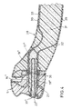
- a plastics roof module 1 is constructed as a sandwich component with an external surface layer 2, an internal surface layer 3 and a filling core 4.
- a plastics side wall module 5 is similarly constructed as a sandwich component with an external surface layer 6, an internal surface layer 7 and a core layer 8.
- the two plastics body modules, the roof module 1 and the side wall module 5, have overlapping 11 and 12 as well as 13 and 14 into which a permanently elastic plastics joining compound 15 requiring a relatively long curing time is introduced.
- plug and socket fixings are formed in two initially separate parts constituted by inserts which are arranged in the plastics modules.
- inserts 18 are formed in the roof module 1 which have through bores defining cavities 16 open at both ends and inserts 19 are formed in the side wall module 5 which define cavities 17 open at only one end.
- the inserts 18 and 19 are additionally formed with annular or thread-like grooves 20 and 21.
- the inserts 18 and 19 can be prefabricated from either metal and plastics material and can be integrally set into the plastics body modules at the strategic points without the need to resort to pull cores in order to prepare the cavities.
- the outer end 25 of the hollow plug 22 is preferably constructed such that it can be covered by superimposed components, for example a blanking cap 37 or a handle 38 (shown in dot-dash lines).
- the fixings at different strategic points between the roof module 1 and the side wall module 5 can have different dimensions in order to allow for the local conditions.
- the cavity 16' in the roof module 1 is relatively short while the cavity 17' in the side wall module 5 is kept larger.
- the corresponding hollow plug 22' is adapted accordingly.
- the plastics floor pan module 28 is again constructed as a sandwich component having an external surface layer 29, an internal surface layer 30 and a core layer 31, reinforcing layers 32 and 33 being in this case added in other areas as required.
- the plastics side wall module 5 still has an external surface layer 6, an internal surface layer 7 and a core layer 8 but is additionally provided with reinforcing layers 34 and 35.
- the reinforcing layers 32 and 33 or 34 and 35 can be formed by corresponding reinforcing fabric inlays or by sheet metal inlays.
- the blind cavity 17'' constructed in the floor pan module 28 is formed in this case by an insert 19'' and the through cavity 16'' provided in the side wall module 5 is formed by a tubular insert 18''.
- the important feature of this arrangement is that these tubular inserts 19'' and 18'' are appropriately surrounded and supported by the corresponding reinforcing layers 32 and 33 or 34 and 35.
- a tubular plug 22'' of suitable length is provided to join together the two inserts. Between the regions of the two plastics body modules hich, under certain circumstances, may fail to lie completely on one another, there can be arranged an annular seal 36 which prevents an undesirable escape of the curable plastics material 27. The free end of the hollow plug 22'' can again be sealed by a blanking cap 37''.
Landscapes
- Engineering & Computer Science (AREA)
- Mechanical Engineering (AREA)
- General Engineering & Computer Science (AREA)
- Chemical & Material Sciences (AREA)
- Combustion & Propulsion (AREA)
- Transportation (AREA)
- Architecture (AREA)
- Structural Engineering (AREA)
- Body Structure For Vehicles (AREA)
- Injection Moulding Of Plastics Or The Like (AREA)
Abstract
Description
- The invention relates to a method and a fixing for joining body modules, in particular plastics body modules of a motor vehicle.
- It is known from EP-A-0 180 554 that different variants of a vehicle can be manufactured by a modular technique. A frame is manufactured, which is common to the variants, and different modules are attached to the frame to form the different variants, for example a hatchback or an estate car version of the same vehicle.
- It is also known that such modules can be manufactured from plastics material and joined to one another by means of an adhesive. Such adhesive joints with plastics compounds, which are designed to be permanently elastic to avoid noise generation and the like, necessitate suitable fixing of the body modules to be joined together, during the curing time of this plastics compound.
- A fixing for fitting a vehicle door to a body part is known from DE-C-3 340 634, in which a solid plug provided on one component is received with clearance in a socket mounted in the other component. The space between the plug and the socket is subsequently filled with a relatively fast curing plastics compound which is injected into the cavity under pressure from the end of the socket opposite to the end from which the plug is introduced into the socket.
- There are two disadvantages with the above proposal. First, access is required to both ends of the socket to allow the plug to be introduced from one end and the curable plastics material to be injected from the other. Second, if a module has several such plug and socket fixings along the adhesive joint, it is difficult to manoeuvre the modules to locate all the plugs at the same time within theirs respective sockets and this difficulty is compounded by the fact that there will inevitably be tolerance errors in the location of the plugs and sockets on their respective modules.
- DE-C-2 602 433 described the securing of a wall mounting plug in a wall to enable a screw to be fixed to the wall. The plug is placed in a hole pre-drilled into the wall and a curable plastics material is injected through the plug into the gap between the plug and the wall. In this way, the plug is held firmly in the wall and one does not rely on the expansion of the plug, which occurs when a screw is driven into the plug, to grip the wall.
- The invention seeks to provide a method and a fixing which enable plastics body modules of motor vehicles to be joined together more simply and in which it is sufficient to have access to only one side of the modules which are to be joined.
- According to one aspect of the invention, there is provided a method of joining two components, such as plastics body modules of a motor vehicle, characterised by the steps of providing inserts recessed into the mating surfaces between the two components, the inserts being opposite one another when the components are in the position in which they are to be joined, there being in each pair of facing inserts a first insert having the form of a socket open at only one end and a second insert having the form of a sleeve open at both ends, holding the components together in the position in which they are to be joined, inserting into each pair of aligned inserts a hollow plug which is received with clearance in the two inserts, and injecting a curable plastics material through the hollow plug into the space between the plug and the two inserts, the plastics material being injected from the same side of the modules as the plug is introduced into the aligned inserts.
- Because there are no protrusions from either of the modules to be joined to one another, the latter can readily be position relative to one another, if necessary after the application of a permanently elastic' jointing compound. The insertion of the plugs and the injection of the plastics material into the inserts can be carried out in a manner corresponding to tack welding of conventional sheet metal body parts.
- According to a second aspect of the invention, there is provided a fixing for joining two components, such as plastics body modules of a motor vehicle, characterised by two inserts to be arranged opposite one another in the two components along the mating surface between the two components, a first insert having the form of a socket open at only one end and the second insert having the form of a sleeve open at both ends, and a hollow plug having an inner end capable of being received with clearance in the two inserts, the outer end of the hollow plug being adapted for connection to a plastics material injection unit to enable a curable plastics material to be injected through the hollow plug into the space between the plug and the two inserts.
- Because here is clearance between the plugs and each of the aligned inserts, a substantial degree of misalignment between the inserts in each pair can be tolerated without impairing the insertion of the plugs and the injection of the fast curing plastics material.
- By suitably shaping of the free end of the hollow plug to form a tight fit with an injection unit, the hollow plug can be used directly as an injection nozzle which allows rapid and deep penetration of the plastics material into the inserts and their complete filling.
- If the walls of the inserts are provided with annular grooves, thread-like grooves or similar keying formations, not only is the common surface between socket and plastics material increased for better adhesion, but a positive keying is also produced.
- Advantageously, the hollow plug may also be provided with annular grooves, thread-type grooves or transverse openings, to improve the adhesion of the plastics material and its distribution in the inserts.
- Conveniently, the inserts may be formed as tubular inserts of metal or plastics material set into into the plastics body modules. In this case, they can be constructed in a desirable manner without the need for cores in the plastics body modules.
- If an annular seal is arranged in the region between the inserts, undesirable escape of the curable plastics material can be avoided.
- The curable plastics compound may suitably consist of a reaction plastics material (a multi-component thermosetting plastics material) which hardens in a load-bearing manner after a predetermined short period of time, or can consist of a fusible plastics material (thermoplastic material) which solidifies in a load-bearing manner after a predetermined short period of time.
- The invention will now be described further, by way of example, with reference to the accompanying drawings, in which:
- Figure 1 shows a partial section through a joint between a plastics roof module and a plastics side wall module at the moment of injection of the curable plastics material,
- Figure 2 shows a similar joint to Figure 1, at a different position and without introduced plastics jointing compound, on completion of injection of the curable plastics material,
- Figure 3 shows an exploded view of a joint between a plastics floor pan module and the door threshold region of a plastics side wall module with the necessary individual parts prior to assembly, and
- Figure 4 shows a partial section through the joint between the plastics floor pan module and the door threshold region of the plastics side wall module.
- In the joint between two plastics body modules, shown in Figures 1 and 2, a
plastics roof module 1 is constructed as a sandwich component with an external surface layer 2, aninternal surface layer 3 and a fillingcore 4. - A plastics
side wall module 5 is similarly constructed as a sandwich component with anexternal surface layer 6, aninternal surface layer 7 and acore layer 8. - A
vehicle door 9, also designed as a plastics component, co-operates with the plasticsside wall module 5 in the usual way via aseal 10. - The two plastics body modules, the
roof module 1 and theside wall module 5, have overlapping 11 and 12 as well as 13 and 14 into which a permanently elastic plastics joining compound 15 requiring a relatively long curing time is introduced. - At strategic points in the
roof module 1 as well as in theside wall module 5 there are provided plug and socket fixings. The sockets of the fixings are formed in two initially separate parts constituted by inserts which are arranged in the plastics modules. In particular,inserts 18 are formed in theroof module 1 which have throughbores defining cavities 16 open at both ends andinserts 19 are formed in theside wall module 5 which definecavities 17 open at only one end. - In the embodiment illustrated in Figure 1, the
inserts like grooves inserts - A
hollow plug 22 with an undulating outer contour 23, anopen tip 24 at its inner end and an openouter end 25, which is preferably constructed such that it can be loaded with the rapidly curingplastics compound 27 directly by aninjection unit 26, is inserted into the mutually alignedcavities outer end 25 of thehollow plug 22 is preferably constructed such that it can be covered by superimposed components, for example ablanking cap 37 or a handle 38 (shown in dot-dash lines). - As shown in Figure 2, the fixings at different strategic points between the
roof module 1 and theside wall module 5 can have different dimensions in order to allow for the local conditions. In the illustrated section through the roof frame of a plastics motor vehicle body, the cavity 16' in theroof module 1 is relatively short while the cavity 17' in theside wall module 5 is kept larger. The corresponding hollow plug 22' is adapted accordingly. - In the joint between a plastics
floor pan module 28 and the door threshold region of theside wall module 5 shown in Figures 3 and 4, other advantageous developments of the invention can be seen. - The plastics
floor pan module 28 is again constructed as a sandwich component having anexternal surface layer 29, aninternal surface layer 30 and acore layer 31, reinforcinglayers - The plastics
side wall module 5 still has anexternal surface layer 6, aninternal surface layer 7 and acore layer 8 but is additionally provided with reinforcinglayers - The reinforcing
layers floor pan module 28 is formed in this case by an insert 19'' and the through cavity 16'' provided in theside wall module 5 is formed by a tubular insert 18''. The important feature of this arrangement, however, is that these tubular inserts 19'' and 18'' are appropriately surrounded and supported by thecorresponding reinforcing layers - A tubular plug 22'' of suitable length is provided to join together the two inserts. Between the regions of the two plastics body modules hich, under certain circumstances, may fail to lie completely on one another, there can be arranged an
annular seal 36 which prevents an undesirable escape of thecurable plastics material 27. The free end of the hollow plug 22'' can again be sealed by a blanking cap 37''. - As shown, in particular, in Figures 2 and 4, it is not absolutely essential for two plastics body modules which are to be joined together also to be joined over broad surface regions by a permanently elastic plastics jointing compound.
Claims (10)
- A method of joining two components, such as body modules of a motor vehicle, characterised by the steps ofa) providing inserts recessed into the mating surface between the two components, the inserts being opposite one another when the components are in the position in which they are to be joined, there being in each pair of facing inserts a first insert having the form of a socket open at only one end and a second insert having the form of a sleeve open at both ends,b) holding the components together in the position in which they are to be joined,c) inserting into each pair of aligned inserts a hollow plug which is received with clearance in the two inserts, andd) injecting a curable plastics material through the hollow plug into the space between the plug and the two inserts, the plastics material being injected from the same side of the modules as the plug is introduced into the aligned inserts.
- A fixing for joining two components, such as plastics body modules of a motor vehicle, characterised bya) two inserts (18,19) to be arranged opposite one another in the two components (1,5) along the mating surface between the two components, a first insert (19) having the form of a socket open at only one end and the second insert (18) having the form of a sleeve open at both ends, andb) a hollow plug (22) having an inner end capable of being received with clearance in the two inserts (18,19), the outer end (25) of the hollow plug (22) being adapted for connection to a plastics material injection unit (26) to enable a curable plastics material to be injected through the hollow plug (22) into the space between the plug and the two inserts (18,19).
- A fixing as claimed in claim 2, characterised in that walls of inserts (18,19) are provided with annular or thread-like grooves (20,21).
- A fixing as claimed in claim 2 or 3, characterised in that the hollow plug (22) is provided with keying formations (23) on its walls.
- A fixing as claimed in any one of claims 2 to 4, characterised in that the inserts (18,19) are integrally set into plastics body modules of a motor vehicle.
- A fixing as claimed in claim 5, characterised in that the inserts (18'',19'') are surrounded by reinforcing layers (32 and 33 or 34 and 35) of the modules.
- A fixing as claimed in any of claims 2 to 6, characterised in that an annular seal (36) is arranged between the inserts to prevent undesired escape of the injected plastics material.
- A fixing as claimed in any of claims 2 to 7, characterised in that a blanking cap (37'') is provided for covering the outer end (25) of the hollow plug (22) after injection of the plastics material.
- A method as claimed in claim 1, characterised in that the plastics material injected into the space between the plug and the two inserts is a multi-component thermosetting plastics material.
- A method as claimed in claim 1, characterised in that the plastics material injected into the space between the plug and the two inserts consists of a fusible thermoplastic material.
Applications Claiming Priority (2)
| Application Number | Priority Date | Filing Date | Title |
|---|---|---|---|
| DE3932196A DE3932196C1 (en) | 1989-09-27 | 1989-09-27 | |
| DE3932196 | 1989-09-27 |
Publications (2)
| Publication Number | Publication Date |
|---|---|
| EP0493514A1 EP0493514A1 (en) | 1992-07-08 |
| EP0493514B1 true EP0493514B1 (en) | 1993-07-21 |
Family
ID=6390280
Family Applications (1)
| Application Number | Title | Priority Date | Filing Date |
|---|---|---|---|
| EP19900915141 Expired - Lifetime EP0493514B1 (en) | 1989-09-27 | 1990-09-26 | Method and fixing for joining body modules |
Country Status (3)
| Country | Link |
|---|---|
| EP (1) | EP0493514B1 (en) |
| DE (2) | DE3932196C1 (en) |
| WO (1) | WO1991004900A1 (en) |
Families Citing this family (13)
| Publication number | Priority date | Publication date | Assignee | Title |
|---|---|---|---|---|
| DE4124627C2 (en) * | 1991-07-25 | 1995-09-21 | Opel Adam Ag | Adhesive connection, in particular glued connection between body parts of motor vehicles |
| DE4142384A1 (en) * | 1991-12-20 | 1993-06-24 | Bayerische Motoren Werke Ag | Plastics component for vehicle e.g. for intakes or trimmings components - comprises threaded section of thermoplastic material with sleeve for plastics insert bonded to plastic component e.g. intake by round or through extrusion |
| DE9202774U1 (en) * | 1992-03-03 | 1992-07-02 | Dethleffs Gmbh, 7972 Isny, De | |
| FR2691200B1 (en) * | 1992-05-18 | 1994-07-29 | Jadot Gerard | HINGE WITH AUTOMATIC ADJUSTMENT OF THE SUPPORTS AND LAYING SYSTEM. |
| FR2696390B1 (en) * | 1992-10-02 | 1994-12-09 | Peugeot | System for attaching an exterior bodywork element to the body of a motor vehicle. |
| DE10135850A1 (en) * | 2001-07-23 | 2003-02-13 | Bayerische Motoren Werke Ag | Power transmission element for adjustment of doors etc. of motor vehicle bodies consists of mandrel and sleeve, with mandrel located and adjusted in sleeve via hardening permanently-elastic adhesive |
| DE10202957A1 (en) | 2002-01-26 | 2003-08-07 | Porsche Ag | Superstructure for motor vehicles |
| DE10202985A1 (en) | 2002-01-26 | 2003-08-07 | Porsche Ag | Superstructure for motor vehicles |
| DE102006026385A1 (en) * | 2006-06-07 | 2007-12-13 | Volkswagen Ag | Frame element e.g. for frame element, has two hollow profile brackets connected to each other by node with carrier provided in opening with first bracket and second carrier arranged in opening of second bracket |
| FR2905664B1 (en) * | 2006-09-13 | 2008-12-12 | Peugeot Citroen Automobiles Sa | CAR PART OF A MOTOR VEHICLE COMPRISING AN ELASTICALLY ELASTICALLY STRESSABLE ELASTIC SOLUTION, A MOTOR VEHICLE AND METHOD OF SOLIDARIZING THE SAME |
| DE102015116840A1 (en) * | 2015-10-05 | 2017-04-06 | Webasto SE | Adhesive method and composite component |
| JP6665846B2 (en) * | 2017-11-01 | 2020-03-13 | マツダ株式会社 | Body structure |
| JP6915600B2 (en) * | 2018-09-28 | 2021-08-04 | マツダ株式会社 | Automotive panel structure |
Family Cites Families (6)
| Publication number | Priority date | Publication date | Assignee | Title |
|---|---|---|---|---|
| DE2602433C2 (en) * | 1976-01-23 | 1984-09-20 | Fischer, Artur, 7244 Waldachtal | Anchoring a fastener |
| DE3248143A1 (en) * | 1982-12-27 | 1984-06-28 | Hilti Ag, Schaan | Dowel which can be fastened by a curable composition |
| DE3322198A1 (en) * | 1983-06-21 | 1985-01-17 | Günter 4930 Detmold Joly | Method for fixing a hollow dowel |
| DE3340634A1 (en) * | 1983-11-10 | 1985-05-30 | Ford-Werke AG, 5000 Köln | METHOD AND DEVICE FOR PRELIMINARY AND / OR FINAL ATTACHMENT OF A VEHICLE DOOR |
| IT1179814B (en) * | 1984-11-02 | 1987-09-16 | Fiat Auto Spa | MOTOR VEHICLE BODY ASSEMBLY METHOD FOR THE PRODUCTION OF DIFFERENT BODYWORKS AND BODYWORK OBTAINED BY TALF METHOD |
| DE3807703C1 (en) * | 1988-03-09 | 1989-08-10 | Huels Troisdorf Ag, 5210 Troisdorf, De | Hinge for vehicles |
-
1989
- 1989-09-27 DE DE3932196A patent/DE3932196C1/de not_active Expired - Lifetime
-
1990
- 1990-09-26 DE DE90915141T patent/DE69002330T2/en not_active Expired - Lifetime
- 1990-09-26 EP EP19900915141 patent/EP0493514B1/en not_active Expired - Lifetime
- 1990-09-26 WO PCT/GB1990/001475 patent/WO1991004900A1/en active IP Right Grant
Also Published As
| Publication number | Publication date |
|---|---|
| WO1991004900A1 (en) | 1991-04-18 |
| EP0493514A1 (en) | 1992-07-08 |
| DE69002330D1 (en) | 1993-08-26 |
| DE69002330T2 (en) | 1994-01-05 |
| DE3932196C1 (en) | 1990-12-13 |
Similar Documents
| Publication | Publication Date | Title |
|---|---|---|
| EP0493514B1 (en) | Method and fixing for joining body modules | |
| US5258157A (en) | Method for joining extruded weather strips and resulting weather strip for motor vehicle | |
| KR20020091276A (en) | Profile composite component and method for the production thereof | |
| US5256077A (en) | Electrical connector shell reinforcement means and method for fabricating same | |
| JP2005315424A (en) | Fastener | |
| MX9504451A (en) | Vehicle assembly method. | |
| KR19980041877A (en) | Press Form Bolt | |
| KR20030001484A (en) | Method and structure for fixing a locking connector to a vehicle member | |
| RU2006108562A (en) | ANGULAR CONNECTION AND METHOD FOR MANUFACTURING THE CONNECTION OF SUCH TYPE | |
| EP3219527A2 (en) | Extruded member corner connection | |
| JP2003231181A (en) | Lap connected board product and method for connecting the same | |
| JPH09504639A (en) | Electromechanical components such as relays with closed casing | |
| US5007761A (en) | Seal arrangement for connecting seals | |
| JPH07238788A (en) | Method for joining shield segment | |
| EP3878719B1 (en) | Systems and methods for joining vehicle components using adhesive | |
| SK134497A3 (en) | Frame for windows, doors, facades or the like | |
| US7090424B2 (en) | Ball-end pin with plastic flange | |
| JPH0357153Y2 (en) | ||
| JP2607050Y2 (en) | Adhesive joints for vehicle roof rails | |
| KR101168817B1 (en) | Insert bolt for fixing garnish used at car tail gate to outer panel of car tail gate | |
| KR0114343Y1 (en) | Rack-valve housing assembly | |
| JPH0736842Y2 (en) | Bonding structure of resin parts | |
| JPH037755Y2 (en) | ||
| WO1999031396A1 (en) | Device and method for fixing the mutual positions of two objects | |
| JPS642076Y2 (en) |
Legal Events
| Date | Code | Title | Description |
|---|---|---|---|
| PUAI | Public reference made under article 153(3) epc to a published international application that has entered the european phase |
Free format text: ORIGINAL CODE: 0009012 |
|
| AK | Designated contracting states |
Kind code of ref document: A1 Designated state(s): DE FR GB |
|
| 17P | Request for examination filed |
Effective date: 19920321 |
|
| 17Q | First examination report despatched |
Effective date: 19921016 |
|
| GRAA | (expected) grant |
Free format text: ORIGINAL CODE: 0009210 |
|
| AK | Designated contracting states |
Kind code of ref document: B1 Designated state(s): DE FR GB |
|
| REF | Corresponds to: |
Ref document number: 69002330 Country of ref document: DE Date of ref document: 19930826 |
|
| ET | Fr: translation filed | ||
| PGFP | Annual fee paid to national office [announced via postgrant information from national office to epo] |
Ref country code: FR Payment date: 19931018 Year of fee payment: 4 |
|
| PLBE | No opposition filed within time limit |
Free format text: ORIGINAL CODE: 0009261 |
|
| STAA | Information on the status of an ep patent application or granted ep patent |
Free format text: STATUS: NO OPPOSITION FILED WITHIN TIME LIMIT |
|
| 26N | No opposition filed | ||
| PGFP | Annual fee paid to national office [announced via postgrant information from national office to epo] |
Ref country code: DE Payment date: 19940913 Year of fee payment: 5 |
|
| PG25 | Lapsed in a contracting state [announced via postgrant information from national office to epo] |
Ref country code: GB Effective date: 19940926 |
|
| PG25 | Lapsed in a contracting state [announced via postgrant information from national office to epo] |
Ref country code: DE Effective date: 19950112 |
|
| GBPC | Gb: european patent ceased through non-payment of renewal fee |
Effective date: 19940926 |
|
| PG25 | Lapsed in a contracting state [announced via postgrant information from national office to epo] |
Ref country code: FR Effective date: 19950531 |
|
| REG | Reference to a national code |
Ref country code: FR Ref legal event code: ST |