EP0034645B1 - Two-step injector for the flue-gas cleaning of dust filters - Google Patents
Two-step injector for the flue-gas cleaning of dust filters Download PDFInfo
- Publication number
- EP0034645B1 EP0034645B1 EP80103529A EP80103529A EP0034645B1 EP 0034645 B1 EP0034645 B1 EP 0034645B1 EP 80103529 A EP80103529 A EP 80103529A EP 80103529 A EP80103529 A EP 80103529A EP 0034645 B1 EP0034645 B1 EP 0034645B1
- Authority
- EP
- European Patent Office
- Prior art keywords
- stage
- filter
- gas
- injector
- filter elements
- Prior art date
- Legal status (The legal status is an assumption and is not a legal conclusion. Google has not performed a legal analysis and makes no representation as to the accuracy of the status listed.)
- Expired
Links
Images

Classifications
-
- B—PERFORMING OPERATIONS; TRANSPORTING
- B01—PHYSICAL OR CHEMICAL PROCESSES OR APPARATUS IN GENERAL
- B01D—SEPARATION
- B01D46/00—Filters or filtering processes specially modified for separating dispersed particles from gases or vapours
- B01D46/02—Particle separators, e.g. dust precipitators, having hollow filters made of flexible material
- B01D46/04—Cleaning filters
-
- B—PERFORMING OPERATIONS; TRANSPORTING
- B01—PHYSICAL OR CHEMICAL PROCESSES OR APPARATUS IN GENERAL
- B01D—SEPARATION
- B01D46/00—Filters or filtering processes specially modified for separating dispersed particles from gases or vapours
- B01D46/42—Auxiliary equipment or operation thereof
- B01D46/4272—Special valve constructions adapted to filters or filter elements
-
- B—PERFORMING OPERATIONS; TRANSPORTING
- B01—PHYSICAL OR CHEMICAL PROCESSES OR APPARATUS IN GENERAL
- B01D—SEPARATION
- B01D46/00—Filters or filtering processes specially modified for separating dispersed particles from gases or vapours
- B01D46/66—Regeneration of the filtering material or filter elements inside the filter
- B01D46/70—Regeneration of the filtering material or filter elements inside the filter by acting counter-currently on the filtering surface, e.g. by flushing on the non-cake side of the filter
- B01D46/71—Regeneration of the filtering material or filter elements inside the filter by acting counter-currently on the filtering surface, e.g. by flushing on the non-cake side of the filter with pressurised gas, e.g. pulsed air
Definitions
- the invention relates to a cleaning device with backwashing device for gas filter elements of dust gas filters, such as filter bags, filter bags or filter cells, in which filter elements for cleaning with the help of flushing gas bursts which are blown into the filter element in counterflow are assigned to two-stage injectors for sucking in clean gas in two stages, one of which is designed as a Coanda annular gap injector and the other as an inlet nozzle.
- a device for cleaning dust separation filters which consists of the following parts: a filter housing with inlet and outlet, filter elements which are connected to the outlet of the filter housing by means of a tubular element outlet, a continuously rotating member and a number connected to a compressed air source and nozzles directed against the element outlets (DE-A-2031011).
- the nozzles consist of ejectors which have an annular gap directed in the intended direction of flow against the element outlets.
- the gap allows the compressed air to flow out around the circumference of a continuous channel that is open at both ends in the ejector.
- the ejectors are connected to the compressed air source by means of a control device in such a way that each ejector emits a momentary compressed air pulse when it passes the relevant element outlet.
- a number, namely four, rows of filter elements arranged concentrically around the central axis are provided in the filter housing.
- the same number, i.e. again four, ejectors is arranged in the carousel.
- Four ejectors are assigned to forty-two filter elements.
- the outlet ends of the ejectors have a substantially smaller cross section than the element outlets and are provided at a distance from them.
- the pressure medium entrains further filtered gas from the collection chamber.
- a conical insert is fitted in the outlet pipe and tapers in the direction of flow of the ejector. This conical insert prevents the cleaning air from flowing back without disturbing the normal flow of the cleaning air into the hose.
- the conical insert should help to increase the pressure in the hose, as well as ensure and improve the cleaning effect.
- a two-stage injector is assigned to each filter element and the inlet nozzle is designed as a cylindrical central injector with a circular cross section that is constant over its length.
- the cross-sectional ratio of the cylindrical outlet pipe of the first stage to the cylindrical inlet nozzle of the second stage can be changed by replacing the cylindrical inlet nozzle.
- the inlet nozzle is integrated in the filter element and has at its inlet a radius which is curved outwards into the clean gas flow and with which it is exchangeably fastened to the support basket for the filter element.
- the outlet end of the first stage is arranged at a distance from the inlet end of the second stage so that the filter stream emerging from the filter elements is discharged via the cylindrical lateral surface between the first and second stages and does not have to pass through the first narrow stage.
- the distance is advantageously one to two times the inner diameter of the outlet pipe of the first stage.
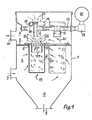
- the device according to the invention consists of a housing 1, which is separated by a partition 2 into a raw gas chamber 3 and a clean gas chamber 4. As many circular openings 5 are provided in the partition 2 as there are filter elements 6.
- the raw gas chamber 3 of the housing 1 is loaded with a raw gas inlet 7 for the dust ne raw gas and provided with a dust discharge 9 for removing the filtered dust.
- the clean gas space 4 has a clean gas outlet 10 for the clean gas.
- Filter elements 6 are suspended in the circular openings 5.
- each inlet nozzle 11 is provided coaxially with the opening of each filter element 6. At its inlet, each inlet nozzle 11 has a radius 12 which points into the clean gas chamber 4 with the curvature outward.
- annular gap injectors 14 with connecting sleeves 15 are attached to the compressed air supply line.
- annular gap injector 14 Arranged on the annular gap injector 14 is an annular channel 16 which opens radially inwardly into an annular gap which is referred to as a “ Coanda” nozzle.
- This gap 17 is smaller than 1 mm and leads radially inwardly to a cylindrical outlet tube 18 of the annular gap injector 14 .
- the cleaned gas is guided through the cylindrical inlet nozzles 11 into the clean gas chamber 4 and from there via the clean gas outlet 10 into the open.
- the filter elements 6 are cleaned at certain intervals of 50 to 300 s by compressed gas during the filtration process.
- the compressed gas is simultaneously blown into the filter elements 6 of a row in the opposite direction to the flow direction of the clean gas 20.
- the compressed gas required for cleaning is generated by a compressed gas compressor (not shown further) and fed to the compressed gas container 21.
- a pressure of 6 bar is present in the compressed gas container 21.
- the compressed gas flow enters the outlet pipes 18 of the first injector stage via the “Coanda” ring gap nozzles 14 and tears secondary gas 23 into the first injector stage.
- the entire purge gas quantity 24, consisting of primary and secondary purge gas quantities, is suddenly pressed into the filter elements 6 via the inlet nozzle 11 and additionally tears a second secondary air quantity 25 suddenly into the filter elements 6.
- a pressure corresponding to the cleaning of the filter elements 6 is built up.
- the dust layer thrown off by the filter elements 6 in this way is collected in the dust collection bunker 8 and discharged from there via the discharge 9. After the magnetically controlled diaphragm valves 22 have closed, the normal filtering flow occurs again for the cleaned filter elements 6.
Abstract
Description
Die Erfindung betrifft eine Reinigungsvorrichtung mit Rückspüleinrichtung für Gasfilterelemente von Staubgasfiltern, wie Filterschläuche, Filtertaschen oder Filterzellen, bei der Filterelementen zum Abreinigen mit Hilfe von Spülgasstössen, die in das Filterelement im Gegenstrom eingeblasen werden, zweistufige Injektoren zum Ansaugen von Reingas in zwei Stufen zugeordnet sind, von denen die eine als Coanda-Ringspaltinjektor und die andere als Einlaufdüse ausgebildet ist.The invention relates to a cleaning device with backwashing device for gas filter elements of dust gas filters, such as filter bags, filter bags or filter cells, in which filter elements for cleaning with the help of flushing gas bursts which are blown into the filter element in counterflow are assigned to two-stage injectors for sucking in clean gas in two stages, one of which is designed as a Coanda annular gap injector and the other as an inlet nozzle.
Es ist eine Vorrichtung zum Reinigen von Staubabscheidefiltern bekannt, die aus folgenden Teilen besteht: einem Filtergehäuse mit Eintritt und Austritt, Filterelementen, die mittels je eines rohrförmigen Elementenaustrittes mit dem Austritt des Filtergehäuses verbunden sind, einem kontinuierlich umlaufenden Glied und einer Anzahl an eine Druckluftquelle angeschlossene und gegen die Elementenaustritte gerichtete Düsen (DE-A-2031011).A device for cleaning dust separation filters is known, which consists of the following parts: a filter housing with inlet and outlet, filter elements which are connected to the outlet of the filter housing by means of a tubular element outlet, a continuously rotating member and a number connected to a compressed air source and nozzles directed against the element outlets (DE-A-2031011).
Die Düsen bestehen aus Ejektoren, die einen in der beabsichtigten Strömungsrichtung gegen die Elementenaustritte gerichteten, ringförmigen Spalt aufweisen. Der Spalt lässt die Druckluft am Umfang eines durchgehenden, an beiden Enden offenen Kanals im Ejektor ausströmen. Dabei sind die Ejektoren mittels einer Steuervorrichtung an die Druckluftquelle derart angeschlossen, dass jeder Ejektor beim Vorbeilauf am betreffenden Elementenaustritt einen momentanen Druckluftstoss abgibt.The nozzles consist of ejectors which have an annular gap directed in the intended direction of flow against the element outlets. The gap allows the compressed air to flow out around the circumference of a continuous channel that is open at both ends in the ejector. The ejectors are connected to the compressed air source by means of a control device in such a way that each ejector emits a momentary compressed air pulse when it passes the relevant element outlet.
Im Filtergehäuse ist eine Anzahl, nämlich vier, konzentrisch um die Mittelachse angeordnete Reihen Filterelemente vorgesehen. Die gleiche Anzahl, also wiederum vier, Ejektoren ist im Karussell angeordnet. Es sind vier Ejektoren zweiundvierzig Filterelemente zugeordnet.A number, namely four, rows of filter elements arranged concentrically around the central axis are provided in the filter housing. The same number, i.e. again four, ejectors is arranged in the carousel. Four ejectors are assigned to forty-two filter elements.
Die Austrittsenden der Ejektoren haben einen wesentlich geringeren Querschnitt als die Elementenaustritte und sind in einigem Abstand von ihnen vorgesehen. Dadurch reisst das Druckmittel weiteres filtriertes Gas aus der Sammelkammer mit. Im Austrittsrohr ist ein kegelförmiger Einsatz angebracht, der sich in Strömungsrichtung des Ejektors verjüngt. Dieser kegelförmige Einsatz verhindert ein Rückströmen der Reinigungsluft, ohne das normale Einströmen der Reinigungsluft in den Schlauch zu stören. Ausserdem soll der kegelförmige Einsatz dazu beitragen, den Druck im Schlauch zu steigern, sowie die Reinigungswirkung sicherzustellen und zu verbessern.The outlet ends of the ejectors have a substantially smaller cross section than the element outlets and are provided at a distance from them. As a result, the pressure medium entrains further filtered gas from the collection chamber. A conical insert is fitted in the outlet pipe and tapers in the direction of flow of the ejector. This conical insert prevents the cleaning air from flowing back without disturbing the normal flow of the cleaning air into the hose. In addition, the conical insert should help to increase the pressure in the hose, as well as ensure and improve the cleaning effect.
Diesem Stand der Technik gegenüber liegt der Erfindung die Aufgabe zugrunde, eine verbesserteReinigungsvorrichtung mit Rückspüleinrichtung für Gasfilterelemente bei Staubgasfiltern zu konzipieren, die
- a) ohne ein kontinuierlich umlaufendes Karussell mit einer Anzahl Düsen auskommt, die mittels einer Steuervorrichtung beim Vorbeilaufen an einem Elementenaustritt einen momentanen Druckstoss abgeben,
- b) einen möglichst geringen Strömungswiderstand für die Druckluft hat und bei der
- c) grosse Spülluftmengen zum Abreinigen der Filterelemente auf engem Raum erzeugt werden.
- a) does not need a continuously rotating carousel with a number of nozzles which, by means of a control device, emit an instantaneous pressure surge when passing an element outlet,
- b) has the lowest possible flow resistance for the compressed air and at
- c) large amounts of purge air for cleaning the filter elements are generated in a small space.
Diese Aufgabe wird mit der Erfindung dadurch gelöst, dass jedem Filterelement ein zweistufiger Injektor zugeordnet ist und die Einlaufdüse als zylindrischer Zentralinjektor mit über seine Länge konstantem Kreisquerschnitt ausgebildet ist.This object is achieved with the invention in that a two-stage injector is assigned to each filter element and the inlet nozzle is designed as a cylindrical central injector with a circular cross section that is constant over its length.
Mit der Erfindung werden der bekannten Reinigungsvorrichtung mit zweistufigen Injektoren, von denen die erste Stufe kontinuierlich umlaufend ausgebildet ist, folgende vorteilhafte Wirkungen zugänglich gemacht:
- 1. eine höhere Spülleistung zum Reinigen der Filterelemente,
- 2. eine geringere Druckluftmenge und damit ein geringerer Energieverbrauch,
- 3. weniger Wartungs-, Instandhaltungs-, Instandsetzungs- und Reparaturarbeiten.
- 1. a higher flushing performance for cleaning the filter elements,
- 2. a lower amount of compressed air and thus lower energy consumption,
- 3. Less maintenance, repair, repair and repair work.
Weitere wesentliche Merkmale der Erfindung sind im folgenden aufgeführt:
- Ein maximaler Volumenstrom mit hoher Austrittsgeschwindigkeit und somit eine höchstmögliche kinetische Energie im Austrittsstrahl der ersten Stufe wird dadurch erzielt bzw. erzeugt, dass der Injektor der ersten Stufe ein Austrittsrohr mit über seine Länge konstantem Querschnitt aufweist.
- A maximum volume flow with a high exit velocity and thus the highest possible kinetic energy in the exit jet of the first stage is achieved or generated in that the injector of the first stage has an outlet pipe with a cross section that is constant over its length.
Um bei unterschiedlichen Filterelementen für die Grösse und Filterfläche eine optimale Druckerhöhung und einen bestmöglichen Volumendurchsatz zu erzielen, ist das Querschnittsverhältnis des zylindrischen Austrittsrohres der ersten Stufe zur zylindrischen Einlaufdüse der zweiten Stufe durch Auswechseln der zylindrischen Einlaufdüse veränderbar.In order to achieve an optimal pressure increase and the best possible volume throughput with different filter elements for the size and filter area, the cross-sectional ratio of the cylindrical outlet pipe of the first stage to the cylindrical inlet nozzle of the second stage can be changed by replacing the cylindrical inlet nozzle.
An Raum wird eingespart dadurch, dass die Einlaufdüse in das Filterelement integriert ist und an ihrem Einlauf einen nach aussen in den Reingasstrom gekrümmten Radius hat, mit dem sie am Stützkorb für das Filterelement auswechselbar befestigt ist.Space is saved by the fact that the inlet nozzle is integrated in the filter element and has at its inlet a radius which is curved outwards into the clean gas flow and with which it is exchangeably fastened to the support basket for the filter element.
Damit der aus den Filterelementen austretende Filterstrom über die zylindrische Mantelfläche zwischen erster und zweiter Stufe abgeführt wird und nicht die erste enge Stufe passieren muss, ist das Austrittsende der ersten Stufe im Abstand zum Eintrittsende der zweiten Stufe angeordnet.The outlet end of the first stage is arranged at a distance from the inlet end of the second stage so that the filter stream emerging from the filter elements is discharged via the cylindrical lateral surface between the first and second stages and does not have to pass through the first narrow stage.
Vorteilhaft beträgt der Abstand das Ein- bis Zweifache des Innendurchmessers des Austrittsrohres der ersten Stufe.The distance is advantageously one to two times the inner diameter of the outlet pipe of the first stage.
Die Erfindung ist in der Zeichnung an einem Ausführungsbeispiel veranschaulicht. Es zeigen:
- Fig. 1 die Vorrichtung von vorn im Längsschnitt und
- Fig. 2 die 1. lnjektorstufe mit Druckluftzuführung.
- Fig. 1 shows the device from the front in longitudinal section and
- Fig. 2 shows the 1st injector stage with compressed air supply.
Die Vorrichtung gemäss der Erfindung besteht aus einem Gehäuse 1, das durch einen Trennboden 2 in eine Rohgaskammer 3 und einen Reingasraum 4 getrennt ist. In dem Trennboden 2 sind soviel kreisförmige Öffnungen 5 vorgesehen wie Filterelemente 6 vorhanden sind.The device according to the invention consists of a
Die Rohgaskammer 3 des Gehäuses 1 ist mit einem Rohgaseinlass 7 für das mit Staub beladene Rohgas und mit einem Staubaustrag 9 zum Abziehen des ausgefilterten Staubes versehen.The
Der Reingasraum 4 hat einen Reingasauslass 10 für das Reingas. In die kreisförmigen Öffnungen 5 sind Filterelemente 6 eingehängt.The
Koaxial zur Öffnung eines jeden Filterelementes 6 ist eine Einlaufdüse 11 vorgesehen. Jede Einlaufdüse 11 hat an ihrem Einlauf einen Radius 12, der mit der Krümmung nach aussen in den Reingasraum 4 weist.An inlet nozzle 11 is provided coaxially with the opening of each filter element 6. At its inlet, each inlet nozzle 11 has a radius 12 which points into the
Im Reingasraum 4 sind an der Druckluftzuführungsleitung 13 Ringspaltinjektoren 14 mit Anschlussmuffen 15 angebracht. Am Ringspaltinjektor 14 ist ein ringförmiger Kanal 16 angeordnet, der nach innen radial in einen Ringspalt mündet, der als "Coanda»-Düse bezeichnet wird. Dieser Spalt 17 ist kleiner als 1 mm und führt radial nach innen zu einem zylindrischen Austrittsrohr 18 des Ringspaltinjektors 14.In the
Die Vorrichtung gemäss der Erfindung arbeitet folgendermassen:
- Das mit Staub
beladene Rohgas 19 wird zur Trennung der Staubanteile vom Rohgas durch den Rohgaseinlass 7 in dieRohgaskammer 3 geführt, strömt dann die Filterelemente 6 von aussen an und tritt durch sie hindurch in sie hinein. Dabei bleiben vor allem die Staubanteile auf den Aussenseiten der Filterelemente 6 haften.
- The
raw gas 19 laden with dust is passed through the raw gas inlet 7 into theraw gas chamber 3 to separate the dust portions from the raw gas, then flows to the filter elements 6 from the outside and passes through them into them. Above all, the dust content sticks to the outside of the filter elements 6.
Das gereinigte Gas wird durch die zylindrischen Einlaufdüsen 11 in die Reingaskammer 4 und von dort aus über den Reingasauslass 10 ins Freie geführt. Die Filterelemente 6 werden in gewissen Intervallabständen von 50 bis 300 s durch Druckgas während des Filtrationsvorganges gereinigt. Hierzu wird das Druckgas in umgekehrter Richtung zur Strömungsrichtung des Reingases 20 gleichzeitig in die Filterelemente 6 einer Reihe eingeblasen.The cleaned gas is guided through the cylindrical inlet nozzles 11 into the
Das für die Reinigung erforderliche Druckgas wird von einem nicht weiter dargestellten Druckgasverdichter erzeugt und dem Druckgasbehälter 21 zugeführt. Im Druckgasbehälter 21 steht ein Druck von 6 bar an. Durch Öffnen der einer zu reinigenden Reihe von Filterelementen 6 zugehörigen magnetgesteuerten Membranventile 22 wird dann für den Bruchteil einer Sekunde ein Druckgasstoss über die in Reihe geschalteten Ringspaltinjektoren 14 in die Injektorrohre 18 gegeben.The compressed gas required for cleaning is generated by a compressed gas compressor (not shown further) and fed to the compressed
Die Druckgasströmung tritt über die «Coanda»-Ringspaltdüsen 14 in die Austrittsrohre 18 der 1. Injektorstufe ein und reisst Sekundärgas 23 in die 1. Injektorstufe. Die gesamte aus Primär- und Sekundärspülgasmenge bestehende Spülgasmenge 24 wird über die Einlaufdüse 11 schlagartig in die Filterelemente 6 gedrückt und reisst zusätzlich eine zweite Sekundärluftmenge 25 schlagartig in die Filterelemente 6. Hier wird ein für die Reinigung der Filterelemente 6 entsprechender Druck aufgebaut.The compressed gas flow enters the
Die Reinigung mittels Druckgas bewirkt hierbei die drei folgenden Funktionen:
- 1. Die normale Filtrationsströmung wird kurzzeitig unterbochen,
- 2. das Filterelement 6 wird durch den Druckgasstrom 24 in Gegenstromrichtung schlagartig aufgeblasen und
- 3. die auf dem Filtermaterial abgelagerte Staubschicht wird durch den primären Druckgasstrom und die zusätzlich zweifach eingezogenen Sekundärspülgasströme 23 und 25 abgeblasen.
- 1. The normal filtration flow is briefly interrupted,
- 2. The filter element 6 is suddenly inflated by the compressed gas flow 24 in the counterflow direction and
- 3. The dust layer deposited on the filter material is blown off by the primary compressed gas stream and the additional double-flushing
gas streams
Die von den Filterelementen 6 auf diese Weise abgeworfene Staubschicht wird im Staubsammelbunker 8 gesammelt und von dort aus über den Austrag 9 abgeführt Nach Schliessen der magnetgesteuerten Membranventile 22 tritt für die gereinigten Filterelemente 6 wieder die normale Filtrierströmung ein.The dust layer thrown off by the filter elements 6 in this way is collected in the
Claims (6)
Priority Applications (1)
| Application Number | Priority Date | Filing Date | Title |
|---|---|---|---|
| AT80103529T ATE9274T1 (en) | 1980-02-07 | 1980-06-24 | TWO-STAGE INJECTOR FOR EXHAUST GAS CLEANING FROM DUST FILTERS. |
Applications Claiming Priority (2)
| Application Number | Priority Date | Filing Date | Title |
|---|---|---|---|
| DE19803004453 DE3004453A1 (en) | 1980-02-07 | 1980-02-07 | TWO-STAGE INJECTOR FOR THE EXHAUST GAS CLEANING OF DUST FILTERS |
| DE3004453 | 1980-02-07 |
Publications (3)
| Publication Number | Publication Date |
|---|---|
| EP0034645A2 EP0034645A2 (en) | 1981-09-02 |
| EP0034645A3 EP0034645A3 (en) | 1982-01-20 |
| EP0034645B1 true EP0034645B1 (en) | 1984-09-12 |
Family
ID=6093959
Family Applications (1)
| Application Number | Title | Priority Date | Filing Date |
|---|---|---|---|
| EP80103529A Expired EP0034645B1 (en) | 1980-02-07 | 1980-06-24 | Two-step injector for the flue-gas cleaning of dust filters |
Country Status (12)
| Country | Link |
|---|---|
| US (1) | US4356010A (en) |
| EP (1) | EP0034645B1 (en) |
| JP (1) | JPS599206B2 (en) |
| AT (1) | ATE9274T1 (en) |
| BR (1) | BR8005233A (en) |
| CS (1) | CS231170B2 (en) |
| DE (1) | DE3004453A1 (en) |
| DK (1) | DK154751C (en) |
| ES (1) | ES8103993A1 (en) |
| HU (1) | HU182167B (en) |
| YU (1) | YU41718B (en) |
| ZA (1) | ZA804275B (en) |
Cited By (2)
| Publication number | Priority date | Publication date | Assignee | Title |
|---|---|---|---|---|
| DE19849639C1 (en) * | 1998-10-28 | 2000-02-10 | Intensiv Filter Gmbh | Airfoil ejector for backwashed filter dust |
| DE102007047276A1 (en) | 2007-10-02 | 2009-04-09 | Intensiv-Filter Gmbh & Co. Kg | Cleaning device for a dust filter |
Families Citing this family (36)
| Publication number | Priority date | Publication date | Assignee | Title |
|---|---|---|---|---|
| US4578092A (en) * | 1983-11-04 | 1986-03-25 | Wehr Corporation | Method and apparatus for improving the operation of a dust collector |
| DE3412758A1 (en) * | 1984-04-05 | 1985-10-17 | Hölter, Heinz, Dipl.-Ing., 4390 Gladbeck | Hot gas filter having a preheating apparatus for flushing gases |
| US4666472A (en) * | 1985-10-15 | 1987-05-19 | Wehr Corporation | Dust collector with deflector means |
| US4759781A (en) * | 1987-03-09 | 1988-07-26 | Olson Robert P | Filtering and dust collecting apparatus |
| US4909813A (en) * | 1989-05-30 | 1990-03-20 | Industrial Filter & Pump Mfg. Co. | Jet pulse extender |
| US5173987A (en) * | 1991-04-12 | 1992-12-29 | Abington, Inc. | Rotary air jet screen cleaning device |
| US5562251A (en) * | 1993-09-03 | 1996-10-08 | Goyen Controls & Co. Pty. Limited | Gas nozzle for bag house cleaning systems |
| DE4334699C1 (en) * | 1993-10-12 | 1994-11-17 | Margraf Adolf | Filtering separator |
| CA2187875A1 (en) * | 1994-04-11 | 1995-10-19 | Jeff Elliott | Components for and methods of operation of bag house filter/cartridge cleaning systems |
| DE19701983C1 (en) * | 1997-01-22 | 1998-06-10 | Matthias Luebbers | Annular ring injector for cleaning dry filter elements in an installation with multiple elements |
| KR100242228B1 (en) * | 1998-03-25 | 2000-02-01 | 최수현 | Apparatus for the high efficiency compact cybagfilter |
| AU8207398A (en) * | 1998-04-24 | 1999-11-16 | Matthias Lubbers | Annular gap injector |
| ATE236701T1 (en) * | 1998-07-16 | 2003-04-15 | Ft Internat B V | ANNUAL GAP INJECTOR |
| EP1029576A1 (en) * | 1999-02-18 | 2000-08-23 | Jetclean GmbH | Apparatus for cleaning a filter |
| AU772518B2 (en) * | 2000-02-02 | 2004-04-29 | Niro A/S | A filter unit for filtering gas |
| DE10041545A1 (en) * | 2000-08-24 | 2002-03-21 | Ft Internat B V | Cleaning device for filter bags in a filter system |
| US7025811B2 (en) * | 2002-08-23 | 2006-04-11 | Cleaire Advanced Emission Controls | Apparatus for cleaning a diesel particulate filter with multiple filtration stages |
| US7799235B2 (en) * | 2004-07-23 | 2010-09-21 | Contech Stormwater Solutions, Inc. | Fluid filter system and related method |
| KR100803721B1 (en) * | 2006-11-01 | 2008-02-15 | 조광섭 | Compressed air supplying device using air amplifier |
| KR100718708B1 (en) * | 2007-02-08 | 2007-05-15 | (주)안성정기 | Injector for bag filter of dust collector |
| KR100730305B1 (en) | 2007-03-09 | 2007-06-19 | 주식회사 삼탑엔지니어링 | A dust collector accelerated pulse air |
| CN100512922C (en) * | 2007-07-05 | 2009-07-15 | 彭志民 | Exterior sieve type bag-type dust remover and its ashing method |
| US8287726B2 (en) | 2007-08-15 | 2012-10-16 | Monteco Ltd | Filter for removing sediment from water |
| TWI360535B (en) * | 2007-08-30 | 2012-03-21 | Univ Nat Sun Yat Sen | Sulfur-containing compound, method of preparation |
| KR100928591B1 (en) * | 2009-03-04 | 2009-11-24 | (주)이진엔지니어링 | Apparatus for jetting compressed air |
| DE102009016145A1 (en) | 2009-04-03 | 2010-10-14 | Intensiv-Filter Gmbh & Co. Kg | Method for cleaning dust-charged gas filter of tubular-filter system, involves removing particulate layer settled on outer surface of filter medium by applying compressed air with specific pressure for specific time period |
| CN102811790B (en) * | 2010-03-24 | 2014-10-15 | 韩国能量技术研究院 | Pulse air injection nozzle with dual columnar slits and bag filter dust removal system using same |
| CN101947083A (en) * | 2010-09-09 | 2011-01-19 | 深圳市康泰健牙科器材有限公司 | Dust collection equipment for dental model workshops and dust collection method thereof |
| JP5574548B2 (en) * | 2011-11-01 | 2014-08-20 | 東北電機鉄工株式会社 | Coanda injector |
| JP2014012234A (en) * | 2012-07-03 | 2014-01-23 | Total Business Solution:Kk | Coanda injector foe cleaning bug filter |
| WO2014136551A1 (en) * | 2013-03-08 | 2014-09-12 | アクロス商事株式会社 | Bag filter air amplification device and bag filter air amplification system using said bag filter air amplification device |
| WO2015104827A1 (en) * | 2014-01-10 | 2015-07-16 | 三菱重工メカトロシステムズ株式会社 | Dust collector device cleaning-use nozzle, and dust collector device |
| JP5722477B2 (en) * | 2014-03-06 | 2015-05-20 | 東北電機鉄工株式会社 | Coanda injector for bag filter cleaning |
| US9976501B2 (en) | 2015-10-26 | 2018-05-22 | Ford Global Technologies, Llc | Methods and systems for rotating an exhaust aftertreatment device |
| KR101942639B1 (en) * | 2017-02-22 | 2019-01-25 | 조광섭 | Bag filter cleaning apparatus for dust collector having large diameter and long length bag filter |
| GB2592267A (en) * | 2020-02-24 | 2021-08-25 | Altair Uk Ltd | Pulse nozzle for filter cleaning systems |
Family Cites Families (15)
| Publication number | Priority date | Publication date | Assignee | Title |
|---|---|---|---|---|
| GB812244A (en) * | 1956-07-09 | 1959-04-22 | Metals Disintegrating Co | A gas filtering apparatus |
| NL250037A (en) * | 1959-04-01 | 1900-01-01 | ||
| DE1407922B2 (en) * | 1963-11-18 | 1973-08-16 | Gebruder Buhler AG, Uzwil (Schweiz) | FILTER SYSTEM FOR DUST SEPARATION FROM AIR |
| US3535852A (en) * | 1967-11-09 | 1970-10-27 | Hydromation Eng Co | High temperature dust collector |
| US3513638A (en) * | 1968-03-08 | 1970-05-26 | Henry T Young | Filter |
| DE2031011A1 (en) * | 1969-06-23 | 1970-12-23 | Kamas Kvarnmaskiner AB., Malmö (Schweden) | Cleaning dust separation filters |
| DE2003908A1 (en) * | 1970-01-29 | 1971-08-05 | Handte Siegfried Dipl Ing | Filter bag backflushing device |
| US3765152A (en) * | 1970-11-04 | 1973-10-16 | Gen Resource Corp | Cleaning of filtering media |
| US3893833A (en) * | 1972-04-26 | 1975-07-08 | Flex Kleen Corp | Compartmented pulse jet dust collector |
| JPS4989961A (en) * | 1972-12-30 | 1974-08-28 | ||
| US3963467A (en) * | 1973-03-08 | 1976-06-15 | Rolschau David W | Dust filter apparatus |
| DE2332031B2 (en) * | 1973-06-23 | 1979-03-22 | Intensiv-Filter Gmbh & Co Kg, 5602 Langenberg | Cleaning device for gas filter elements |
| US3874857A (en) * | 1974-01-07 | 1975-04-01 | Spencer Turbine Co | Apparatus for filtering particulate matter from gas and having reverse flow cleaning means |
| US4073632A (en) * | 1975-07-07 | 1978-02-14 | United States Filter Corporation | Filter bag assembly |
| CH604847A5 (en) * | 1976-01-15 | 1978-09-15 | Ind Patente Anstalt |
-
1980
- 1980-02-07 DE DE19803004453 patent/DE3004453A1/en not_active Ceased
- 1980-06-09 CS CS804060A patent/CS231170B2/en unknown
- 1980-06-19 YU YU1610/80A patent/YU41718B/en unknown
- 1980-06-24 AT AT80103529T patent/ATE9274T1/en active
- 1980-06-24 EP EP80103529A patent/EP0034645B1/en not_active Expired
- 1980-07-07 US US06/166,736 patent/US4356010A/en not_active Expired - Lifetime
- 1980-07-10 HU HU801731A patent/HU182167B/en unknown
- 1980-07-14 DK DK304480A patent/DK154751C/en not_active IP Right Cessation
- 1980-07-15 ZA ZA00804275A patent/ZA804275B/en unknown
- 1980-07-30 ES ES493833A patent/ES8103993A1/en not_active Expired
- 1980-08-19 BR BR8005233A patent/BR8005233A/en unknown
- 1980-09-16 JP JP55127341A patent/JPS599206B2/en not_active Expired
Cited By (2)
| Publication number | Priority date | Publication date | Assignee | Title |
|---|---|---|---|---|
| DE19849639C1 (en) * | 1998-10-28 | 2000-02-10 | Intensiv Filter Gmbh | Airfoil ejector for backwashed filter dust |
| DE102007047276A1 (en) | 2007-10-02 | 2009-04-09 | Intensiv-Filter Gmbh & Co. Kg | Cleaning device for a dust filter |
Also Published As
| Publication number | Publication date |
|---|---|
| BR8005233A (en) | 1981-08-11 |
| ZA804275B (en) | 1981-07-29 |
| EP0034645A2 (en) | 1981-09-02 |
| YU161080A (en) | 1983-02-28 |
| ATE9274T1 (en) | 1984-09-15 |
| US4356010A (en) | 1982-10-26 |
| EP0034645A3 (en) | 1982-01-20 |
| DK154751B (en) | 1988-12-19 |
| CS406080A2 (en) | 1984-02-13 |
| DK304480A (en) | 1981-08-08 |
| ES493833A0 (en) | 1981-04-01 |
| CS231170B2 (en) | 1984-10-15 |
| HU182167B (en) | 1983-12-28 |
| DK154751C (en) | 1989-05-01 |
| ES8103993A1 (en) | 1981-04-01 |
| YU41718B (en) | 1987-12-31 |
| DE3004453A1 (en) | 1981-08-13 |
| JPS56113318A (en) | 1981-09-07 |
| JPS599206B2 (en) | 1984-03-01 |
Similar Documents
| Publication | Publication Date | Title |
|---|---|---|
| EP0034645B1 (en) | Two-step injector for the flue-gas cleaning of dust filters | |
| DE1757370C3 (en) | Gas filter | |
| DE102015006497B4 (en) | Cyclone separator and filter device with cyclone separator | |
| DE2825273A1 (en) | SEPARATOR | |
| DE3125503C2 (en) | Device for classifying spherical elastic solids for cleaning heat exchanger tubes | |
| DE2328220A1 (en) | DEVICE AND METHOD FOR GENERATING A Vortex | |
| EP1177828A2 (en) | Device for separating liquids and /or solid matters or gases from a gas stream having different specific weight | |
| DE2332031B2 (en) | Cleaning device for gas filter elements | |
| WO2015055157A1 (en) | Filter system having a rotary filter | |
| DE2803224C2 (en) | Self-cleaning filter device | |
| DE102013017266A1 (en) | Filter system with a rotary filter | |
| DE202006005677U1 (en) | Filter assembly for dust-laden raw gas has array of hanging bags with base inlets | |
| EP0338314A1 (en) | Installation for recovering powder for powder-coating plants or the like | |
| EP0636049B1 (en) | Device for the uniform distribution of a two-phase stream | |
| EP1009514B1 (en) | Dust filter | |
| EP1095688B1 (en) | Dust filter | |
| DE3341281C2 (en) | ||
| EP1507579B1 (en) | Cleaning device for tubular filter elements | |
| DE2031011A1 (en) | Cleaning dust separation filters | |
| DE202013009217U1 (en) | Filter system with a rotary filter | |
| DE202013009510U1 (en) | Nozzle head and cleaning device with such a nozzle head | |
| DE2652552C3 (en) | Method and device for regenerating a carcass bag filter | |
| AT350591B (en) | DEVICE FOR CLEANING UP FILTER HOSES FROM THE OUTSIDE | |
| DE2905289C2 (en) | Device for cleaning a gas | |
| DE102016004496B4 (en) | Separating device and method for the separation of particles from an intake air of an internal combustion engine |
Legal Events
| Date | Code | Title | Description |
|---|---|---|---|
| PUAI | Public reference made under article 153(3) epc to a published international application that has entered the european phase |
Free format text: ORIGINAL CODE: 0009012 |
|
| AK | Designated contracting states |
Designated state(s): AT BE CH FR GB IT NL SE |
|
| PUAL | Search report despatched |
Free format text: ORIGINAL CODE: 0009013 |
|
| AK | Designated contracting states |
Designated state(s): AT BE CH FR GB IT NL SE |
|
| 17P | Request for examination filed |
Effective date: 19820225 |
|
| ITF | It: translation for a ep patent filed |
Owner name: DR. ING. A. RACHELI & C. |
|
| GRAA | (expected) grant |
Free format text: ORIGINAL CODE: 0009210 |
|
| STAA | Information on the status of an ep patent application or granted ep patent |
Free format text: STATUS: THE PATENT HAS BEEN GRANTED |
|
| AK | Designated contracting states |
Designated state(s): AT BE CH FR GB IT LI NL SE |
|
| REF | Corresponds to: |
Ref document number: 9274 Country of ref document: AT Date of ref document: 19840915 Kind code of ref document: T |
|
| ET | Fr: translation filed | ||
| PLBE | No opposition filed within time limit |
Free format text: ORIGINAL CODE: 0009261 |
|
| 26N | No opposition filed | ||
| ITTA | It: last paid annual fee | ||
| EAL | Se: european patent in force in sweden |
Ref document number: 80103529.6 |
|
| PGFP | Annual fee paid to national office [announced via postgrant information from national office to epo] |
Ref country code: SE Payment date: 19960521 Year of fee payment: 17 |
|
| PG25 | Lapsed in a contracting state [announced via postgrant information from national office to epo] |
Ref country code: SE Effective date: 19970625 |
|
| EUG | Se: european patent has lapsed |
Ref document number: 80103529.6 |
|
| PGFP | Annual fee paid to national office [announced via postgrant information from national office to epo] |
Ref country code: GB Payment date: 19990511 Year of fee payment: 20 |
|
| PGFP | Annual fee paid to national office [announced via postgrant information from national office to epo] |
Ref country code: FR Payment date: 19990512 Year of fee payment: 20 |
|
| PGFP | Annual fee paid to national office [announced via postgrant information from national office to epo] |
Ref country code: CH Payment date: 19990514 Year of fee payment: 20 |
|
| PGFP | Annual fee paid to national office [announced via postgrant information from national office to epo] |
Ref country code: AT Payment date: 19990521 Year of fee payment: 20 |
|
| PGFP | Annual fee paid to national office [announced via postgrant information from national office to epo] |
Ref country code: NL Payment date: 19990527 Year of fee payment: 20 |
|
| PGFP | Annual fee paid to national office [announced via postgrant information from national office to epo] |
Ref country code: BE Payment date: 19990614 Year of fee payment: 20 |
|
| BE20 | Be: patent expired |
Free format text: 20000624 *INTENSIV-FILTER G.M.B.H. & CO K.G. |
|
| PG25 | Lapsed in a contracting state [announced via postgrant information from national office to epo] |
Ref country code: LI Free format text: LAPSE BECAUSE OF NON-PAYMENT OF DUE FEES Effective date: 20000623 Ref country code: GB Free format text: LAPSE BECAUSE OF EXPIRATION OF PROTECTION Effective date: 20000623 Ref country code: CH Free format text: LAPSE BECAUSE OF NON-PAYMENT OF DUE FEES Effective date: 20000623 |
|
| PG25 | Lapsed in a contracting state [announced via postgrant information from national office to epo] |
Ref country code: NL Free format text: LAPSE BECAUSE OF EXPIRATION OF PROTECTION Effective date: 20000624 Ref country code: AT Free format text: LAPSE BECAUSE OF EXPIRATION OF PROTECTION Effective date: 20000624 |
|
| REG | Reference to a national code |
Ref country code: CH Ref legal event code: PL |
|
| REG | Reference to a national code |
Ref country code: GB Ref legal event code: PE20 Effective date: 20000623 |
|
| NLV7 | Nl: ceased due to reaching the maximum lifetime of a patent |
Effective date: 20000624 |