EP0034645A2 - Two-step injector for the flue-gas cleaning of dust filters - Google Patents
Two-step injector for the flue-gas cleaning of dust filters Download PDFInfo
- Publication number
- EP0034645A2 EP0034645A2 EP80103529A EP80103529A EP0034645A2 EP 0034645 A2 EP0034645 A2 EP 0034645A2 EP 80103529 A EP80103529 A EP 80103529A EP 80103529 A EP80103529 A EP 80103529A EP 0034645 A2 EP0034645 A2 EP 0034645A2
- Authority
- EP
- European Patent Office
- Prior art keywords
- stage
- filter
- injector
- gas
- inlet nozzle
- Prior art date
- Legal status (The legal status is an assumption and is not a legal conclusion. Google has not performed a legal analysis and makes no representation as to the accuracy of the status listed.)
- Granted
Links
Images
Classifications
-
- B—PERFORMING OPERATIONS; TRANSPORTING
- B01—PHYSICAL OR CHEMICAL PROCESSES OR APPARATUS IN GENERAL
- B01D—SEPARATION
- B01D46/00—Filters or filtering processes specially modified for separating dispersed particles from gases or vapours
- B01D46/02—Particle separators, e.g. dust precipitators, having hollow filters made of flexible material
- B01D46/04—Cleaning filters
-
- B—PERFORMING OPERATIONS; TRANSPORTING
- B01—PHYSICAL OR CHEMICAL PROCESSES OR APPARATUS IN GENERAL
- B01D—SEPARATION
- B01D46/00—Filters or filtering processes specially modified for separating dispersed particles from gases or vapours
- B01D46/42—Auxiliary equipment or operation thereof
- B01D46/4272—Special valve constructions adapted to filters or filter elements
-
- B—PERFORMING OPERATIONS; TRANSPORTING
- B01—PHYSICAL OR CHEMICAL PROCESSES OR APPARATUS IN GENERAL
- B01D—SEPARATION
- B01D46/00—Filters or filtering processes specially modified for separating dispersed particles from gases or vapours
- B01D46/66—Regeneration of the filtering material or filter elements inside the filter
- B01D46/70—Regeneration of the filtering material or filter elements inside the filter by acting counter-currently on the filtering surface, e.g. by flushing on the non-cake side of the filter
- B01D46/71—Regeneration of the filtering material or filter elements inside the filter by acting counter-currently on the filtering surface, e.g. by flushing on the non-cake side of the filter with pressurised gas, e.g. pulsed air
Definitions
- the invention relates to a cleaning device with backwashing device for gas filter elements of dust gas filters, such as filter bags, filter bags or filter cells, in which each filter element for cleaning with the help of flushing gas bursts that are blown into the filter element in counterflow, a two-stage injector for sucking clean gas in two stages is.
- the invention has for its object to design an improved cleaning device in which large amounts of purge air are generated to clean the filter elements in a confined space.
- the first stage is designed as a "Coanda" annular gap injector known per se and the second stage is designed as an inlet nozzle.
- the two-stage injector achieves a significantly higher flushing performance for cleaning the filter elements. At the same time, the amount of compressed air is reduced and thus energy consumption is reduced.
- the inlet nozzle designed for high throughputs, enables secondary air to be fed into the filter element. This is additionally guided into the filter element between the injector outlet of the first stage and the injector inlet of the second stage. The pressure required to clean the filter elements is only built up in the second stage. Another advantage is that mass flow ratios of 9/8: 1 can be achieved.
- the inlet nozzle of the second stage is designed as a cylindrical central injector with a circular cross-section that is constant over its length.
- the cross-sectional ratio of the cylindrical outlet pipe of the first stage to the cylindrical inlet nozzle of the second stage can be changed by replacing the cylindrical inlet nozzle.
- the inlet nozzle is integrated in the filter element and at its inlet has a radius which is curved outwards into the clean gas space and with which it is exchangeably fastened to the support basket for the filter element.
- the outlet end of the first stage is arranged at a distance from the inlet end of the second stage so that the filtering stream emerging from the filter elements is discharged via the cylindrical lateral surface between the first and second stages and does not have to pass through the narrow first stage.
- the distance is advantageously one to two times the inner diameter of the outlet pipe of the first stage.
- the device according to the invention consists of a housing 1, which is separated by a partition 2 into a raw gas chamber 3 and a clean gas chamber 4. As many circular openings 5 are provided in the partition 2 as there are filter elements 6.
- the raw gas chamber 3 of the housing is provided with a raw gas inlet 7 for the raw gas laden with dust and with a dust discharge 9 for removing the filtered dust.
- the clean gas chamber 4 has a clean gas outlet 10 for the clean gas.
- Filter elements 6 are suspended in the circular openings 5.
- each inlet nozzle 11 Is coaxial to the opening of each filter element 6 an inlet nozzle 11 is provided.
- Each inlet nozzle 11 has a radius 12 at its inlet, which points into the clean gas space 4 with the curvature outward.
- annular gap injectors 14 with connecting sleeves 15 are attached to the compressed air supply line 13.
- annular channel 16 Arranged on the annular gap injector 14 is an annular channel 16 which opens radially inwards into an annular gap which is referred to as a "Coanda" nozzle.
- This gap 17 is smaller than 1 mm and leads radially inwards to a cylindrical outlet tube 18 of the annular gap injector 14.
- the cleaned gas is passed through the cylindrical inlet nozzles 11 into the clean gas chamber 4 and from there via the clean gas outlet 10 into the open.
- the filter elements 6 are cleaned at certain intervals of 50 to 300 s by compressed gas during the filtration process.
- the compressed gas is simultaneously blown into the filter elements 6 of a row in the opposite direction to the flow direction of the clean gas 20.
- the compressed gas required for cleaning is from generated a compressed gas compressor not shown and fed to the compressed gas container 21.
- a pressure of 6 bar is present in the compressed gas container 21.
- a pressure gas surge is then given for a fraction of a second via the annular gap injectors 14 connected in series into the injector tubes 18.
- the compressed gas flow enters the injector tubes 18 of the first injector stage via the “Coanda” annular gap nozzles 14 and tears secondary gas 23 into the first injector stage.
- the total amount of purge gas 24 consisting of primary and secondary purge gas is suddenly pressed into the filter elements 6 via the inlet nozzle 11 and additionally tears a second amount of secondary air 25 suddenly into the filter elements 6.
- a pressure corresponding to the cleaning of the filter elements 6 is built up.
- the dust layer thrown off by the filter elements 6 in this way is collected in the dust collection bunker 6 and discharged from there via the discharge 9. After closing the magnetically controlled diaphragm valves 22, the normal filtering flow occurs again for the cleaned filter elements 6.
Landscapes
- Chemical & Material Sciences (AREA)
- Chemical Kinetics & Catalysis (AREA)
- Filtering Of Dispersed Particles In Gases (AREA)
- Cleaning By Liquid Or Steam (AREA)
- Radiation-Therapy Devices (AREA)
- Physical Vapour Deposition (AREA)
- Filtering Materials (AREA)
Abstract
Description
Die Erfindung betrifft eine Reinigungsvorrichtung mit Rückspüleinrichtung für Gasfilterelemente von Staubgasfiltern, wie Filterschläuche, Filtertaschen oder Filterzellen, bei der jedem Filterelement zum Abreinigen mit Hilfe von Spülgasstößen, die in das Filterelement im Gegenstrom eingeblasen werden, ein zweistufiger Injektor zum Ansaugen von Reingas in zwei Stufen zugeordnet ist.The invention relates to a cleaning device with backwashing device for gas filter elements of dust gas filters, such as filter bags, filter bags or filter cells, in which each filter element for cleaning with the help of flushing gas bursts that are blown into the filter element in counterflow, a two-stage injector for sucking clean gas in two stages is.
Bekannt sind Abreinigungsvorrichtungen für Gasfilterelemente mit einstufigen Injektoren. Diese haben jedoch den Nachteil einer vergleichsweise geringen Spülluftmenge zur Abreinigung der Filterelemente. Weiter sind zweistufige Injektoren zur Abreinigung von Gasfilterelementen bekannt (DE-PS 12 28 130), die jedoch in der ersten und zweiten Stufe Zentralinjektoren verwenden, die auch keine wesentlich höheren Spülluftmengen erzeugen.Cleaning devices for gas filter elements with single-stage injectors are known. However, these have the disadvantage of a comparatively small amount of purge air for cleaning the filter elements. Furthermore, two-stage injectors for cleaning gas filter elements are known (DE-PS 12 28 130), which, however, use central injectors in the first and second stages, which also do not generate much higher amounts of purge air.
Der Erfindung liegt die Aufgabe zugrunde, eine verbesserte Abreinigungsvorrichtung zu konzipieren, bei der große Spülluftmengen zum Abreinigen der Filterelemente auf engem Raum erzeugt werden.The invention has for its object to design an improved cleaning device in which large amounts of purge air are generated to clean the filter elements in a confined space.
Diese Aufgabe wird gemäß der Erfindung dadurch gelöst, daß die erste Stufe als ein an sich bekannter "Coanda"-Ringspaltinjektor und die zweite Stufe als Einlaufdüse ausgebildet ist.This object is achieved according to the invention in that the first stage is designed as a "Coanda" annular gap injector known per se and the second stage is designed as an inlet nozzle.
Der mit der Erfindung erzielbare technische Fortschritt beruht auf mehreren Vorteilen: Bei der "Coanda"-Ringspaltdüse tritt der Primärluftstrom radial aus dem Ringspalt aus, wird an der gekrümmten Wand entlang geführt und in axiale Richtung umgelenkt. Der Primärstrom überträgt hierbei seinen Impuls auf den innen liegenden Sekundärstrom. Dieses Phänomen wird als "Coanda" - Effekt bezeichnet.The technical progress achievable with the invention is based on several advantages: With the "Coanda" annular gap nozzle, the primary air stream emerges radially from the annular gap, is guided along the curved wall and is deflected in the axial direction. The primary current transfers its impulse to the internal secondary current. This phenomenon is called the "Coanda" effect.
Mit dem Zwei-Stufen-Injektor wird eine wesentlich höhere Spülleistung zum Reinigen der Filterlemente erreicht. Gleichzeitig wird die Druckluftmenge reduziert und damit der Energieverbrauch vermindert. Die für große Durchsätze konzipierte Einlaufdüse ermöglicht die weitere Zufuhr von Sekundärluft in das Filterelement. Diese wird zwischen Injektoraustritt der ersten Stufe und Injektoreintritt der zweiten Stufe zusätzlich in das Filterelement geführt. Der erforderliche Druck für die Abreinigung der Filterelemente wird hierbei nur in der zweiten Stufe aufgebaut. Ein weiterer Vorteil besteht darin, daß sich Massenstromverhältnisse von 9/8 : 1 erzielen lassen.The two-stage injector achieves a significantly higher flushing performance for cleaning the filter elements. At the same time, the amount of compressed air is reduced and thus energy consumption is reduced. The inlet nozzle, designed for high throughputs, enables secondary air to be fed into the filter element. This is additionally guided into the filter element between the injector outlet of the first stage and the injector inlet of the second stage. The pressure required to clean the filter elements is only built up in the second stage. Another advantage is that mass flow ratios of 9/8: 1 can be achieved.
Bei geringem Druckluftverbrauch sind hohe Spülluftmengen für die Reinigung der Filterelemente zu verwirklichen. In der Filterphase strömen jedoch die gereinigten Gase über die Einlaufdüse unter Umgehung der ersten Injektorstufe direkt zum Reingas, brauchen also nicht die relativ enge erste Injektorstufe zu durchströmen.With low compressed air consumption, high amounts of purge air can be achieved for cleaning the filter elements. In the filter phase, however, the cleaned ones flow Gases via the inlet nozzle bypassing the first injector stage directly to the clean gas do not need to flow through the relatively narrow first injector stage.
Weitere wesentliche Merkmale der Erfindung sind im folgenden aufgeführt:
- Ein maximaler Volumenstrom mit hoher Austrittsgeschwindigkeit und somit eine höchst mögliche kinetische Energie im Austrittsstrahl der ersten Stufe wird dadurch erzielt bzw. erzeugt, daß das Injektorrohr der ersten Stufe als zylindrisches Austrittsrohr mit über seine Länge konstantem Kreisquerschnitt ausgebildet ist.
- A maximum volume flow with a high exit velocity and thus the highest possible kinetic energy in the exit jet of the first stage is achieved or generated in that the injector tube of the first stage is designed as a cylindrical outlet tube with a circular cross section that is constant over its length.
Um den Druckaufbau in der zweiten Stufe zu intensivieren, ist die Einlaufdüse der zweiten Stufe als zylindrischer Zentralinjektor mit über seine Länge konstantem Kreisquerschnitt ausgebildet.In order to intensify the pressure build-up in the second stage, the inlet nozzle of the second stage is designed as a cylindrical central injector with a circular cross-section that is constant over its length.
Um bei unterschiedlichen Filterelementen für die Größe und Filterfläche eine optimale Druckerhöhung und einen bestmöglichen Volumendurchsatz zu erzielen, ist das Querschnittsverhältnis des zylindrischen Austrittsrohres der ersten Stufe zur zylindrischen Einlaufdüse der zweiten Stufe durch Auswechseln der zylindrischen Einlaufdüse veränderbar.In order to achieve an optimal pressure increase and the best possible volume throughput with different filter elements for the size and filter area, the cross-sectional ratio of the cylindrical outlet pipe of the first stage to the cylindrical inlet nozzle of the second stage can be changed by replacing the cylindrical inlet nozzle.
An Raum wird eingespart dadurch, daß die Einlaufdüse in das Filterelement integiert ist und an ihrem Einlauf einen nach außen in den Reingasraum gekrümmten Radius hat, mit dem sie am Stützkorb für das Filterelement auswechselbar befestigt ist.Space is saved by the fact that the inlet nozzle is integrated in the filter element and at its inlet has a radius which is curved outwards into the clean gas space and with which it is exchangeably fastened to the support basket for the filter element.
Damit der aus den Filterelementen austretende Filtrierstrom über die zylindrische Mantelfläche zwischen erster und zweiter Stufe abgeführt wird und nicht die enge erste Stufe passieren muß, ist das Austrittsende der ersten Stufe im Abstand vom Eintrittsende der zweiten Stufe angeordnet.The outlet end of the first stage is arranged at a distance from the inlet end of the second stage so that the filtering stream emerging from the filter elements is discharged via the cylindrical lateral surface between the first and second stages and does not have to pass through the narrow first stage.
Vorteilhaft beträgt der Abstand das ein- bis zweifache des Innendurchmessers des Austrittsrohres der ersten Stufe.The distance is advantageously one to two times the inner diameter of the outlet pipe of the first stage.
Die Erfindung ist in der Zeichnung an einem Ausführungsbeispiel veranschaulicht. Es zeigen:
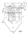
- Fig. 1 die Vorrichtung von vorn im Längsschnitt und
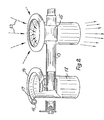
- Fig. 2 die 1. Injektorstufe mit Druckluftzuführung.
- Fig. 1 shows the device from the front in longitudinal section and
- Fig. 2, the 1st injector stage with compressed air supply.
Die Vorrichtung gemäß der Erfindung besteht aus einem Gehäuse 1, das durch einen Trennboden 2 in eine Rohgaskammer 3 und eine Reingaskammer 4 getrennt ist. In dem Trennboden 2 sind soviel kreisförmige Öffnungen 5 vorgesehen, wie Filterelemente 6 vorhanden sind.The device according to the invention consists of a housing 1, which is separated by a
Die Rohgaskammer 3 des Gehäuses ist mit einem Rohgaseinlaß 7 für das mit Staub beladene Rohgas und mit einem Staubaustrag 9 zum Abziehen des ausgefilterten Staubes versehen.The
Die Reingaskammer 4 hat einen Reingasauslaß 10 für das Reingas. In die kreisförmigen Öffnungen 5 sind Filterelemente 6 eingehängt.The clean gas chamber 4 has a
Koaxial zur Öffnung eines jeden Filterelementes 6 ist eine Einlaufdüse 11 vorgesehen. Jede Einlaufdüse 11 hat an ihrem Einlauf einen Radius 12, der mit der Krümmung nach außen in den Reingasraum 4 weist.Is coaxial to the opening of each filter element 6 an
Im Reingasraum 4 sind an der Druckluftzuführungsleitung 13 Ringspaltinjektoren 14 mit Anschlußmuffen 15 angebracht. Am Ringspaltinjektor 14 ist ein ringförmiger Kanal 16 angeordnet, der nach innen radial in einen Ringspalt mündet, der als "Coanda" - Düse bezeichnet wird. Dieser Spalt 17 ist kleiner als 1 mm und führt radial nach innen zu einem zylindrischen Austrittsrohr 18 des Ringspaltinjektors 14.In the clean gas chamber 4,
Die Vorrichtung gemäß der Erfindung arbeitet folgendermaßen:
- Das mit Staub
beladene Rohgas 19 wird zur Trennung der Staubanteile vom Rohgas durch den Rohgaseinlaß 17 in dieRohgaskammer 3 geführt, strömt dann die Filterelemente 6 von außen an und tritt durch sie hindurch in sie hinein. Dabei bleiben vor allem die Staubanteile auf den Außenseiten der Filterelemente 6 haften.
- The
raw gas 19 laden with dust is passed through the raw gas inlet 17 into theraw gas chamber 3 to separate the dust portions from the raw gas, then flows to the filter elements 6 from the outside and passes through them into them. Above all, the dust content sticks to the outside of the filter elements 6.
Das gereinigte Gas wird durch die zylindrischen Einlaufdüsen 11 in die Reingaskammer 4 und von dort aus über den Reingasauslaß 10 ins Freie geführt. Die Filterelemente 6 werden in gewissen Intervallabständen von 50 bis 300 s durch Druckgas während des Filtrationsvorganges gereinigt. Hierzu wird das Druckgas in umgekehrter Richtung zur Strömungsrichtung des Reingases 20 gleichzeitig in die Filterelemente 6 einer Reihe eingeblasen.The cleaned gas is passed through the
Das für die Reinigung erforderliche Druckgas wird von einem nicht weiter dargestellten Druckgasverdichter erzeugt und dem Druckgasbehälter 21 zugeführt. Im Druckgasbehälter 21 steht ein Druck von 6 bar an. Durch Öffnen der einer zu reinigenden Reihe von Filterelementen 6 zugehörigen magnetgesteuerten Membranventile 22 wird dann für den Bruchteil einer Sekunde ein Druckgasstoß über die in Reihe geschalteten Ringspaltinjektoren 14 in die Injektorrohre 18 gegeben.The compressed gas required for cleaning is from generated a compressed gas compressor not shown and fed to the compressed
Die Druckgasströmung tritt über die "Coanda" - Ringspaltdüsen14 in die Injektorrohre 18 der 1. Injektorstufe ein und reißt Sekundärgas 23 in die 1. Injektorstufe. Die gesamte aus Primär- und Sekundärspülgasmenge bestehende Spülgasmenge 24 wird über die Einlaufdüse 11 schlagartig in die Filterelemente 6 gedrückt und reißt zusätzlich eine zweite Sekundärluftmenge 25 schlagartig in die Filterelemente 6. Hier wird ein für die Reinigung der Filterelemente 6 entsprechender Druck aufgebaut.The compressed gas flow enters the
Die Reinigung mittels Druckgas bewirkt hierbei die drei folgenden Funktionen:
- 1. Die normale Filtrationsströmung wird kurzzeitig unterbrochen,
- 2. das Filterelement 6 wird durch den Druckgasstrom 24 in Gegenstromrichtung schlagartig aufgeblasen und
- 3. die auf dem Filtermaterial abgelagerte Staubschicht wird durch den primären Druckgasstrom und die zusätzlich zweifach
eingezogenen Sekundärspülgasströme 23 und 25 abgeblasen.
- 1. The normal filtration flow is briefly interrupted,
- 2. The filter element 6 is suddenly inflated by the compressed gas flow 24 in the counterflow direction and
- 3. The dust layer deposited on the filter material is blown off by the primary compressed gas stream and the additional double-flushing
gas streams
Die von den Filterelementen 6 auf diese Weise abgeworfene Staubschicht wird im Staubsammelbunker 6 gesammelt und von dort aus über den Austrag 9 abgeführt. Nach Schließen der magnetgesteuerten Membranventile 22 tritt für die gereinigten Filterelemente 6 wieder die normale Filtrierströmung ein.The dust layer thrown off by the filter elements 6 in this way is collected in the dust collection bunker 6 and discharged from there via the discharge 9. After closing the magnetically controlled
Claims (7)
dadurch gekennzeichnet,
daß die erste Stufe als ein an sich bekannter "Coanda"-Ringspaltinjektor (14) und die zweite Stufe als Einlaufdüse (11) ausgebildet ist.1.Cleaning device with backwashing device for gas filter elements of dust gas filters, such as filter bags, filter bags or filter cells, in which each filter element is assigned a two-stage injector for sucking in clean gas in two stages for cleaning with the help of flushing gas bursts which are blown into the filter element in counterflow,
characterized,
that the first stage is designed as a known "Coanda" annular gap injector (14) and the second stage as an inlet nozzle (11).
Priority Applications (1)
| Application Number | Priority Date | Filing Date | Title |
|---|---|---|---|
| AT80103529T ATE9274T1 (en) | 1980-02-07 | 1980-06-24 | TWO-STAGE INJECTOR FOR EXHAUST GAS CLEANING FROM DUST FILTERS. |
Applications Claiming Priority (2)
| Application Number | Priority Date | Filing Date | Title |
|---|---|---|---|
| DE3004453 | 1980-02-07 | ||
| DE19803004453 DE3004453A1 (en) | 1980-02-07 | 1980-02-07 | TWO-STAGE INJECTOR FOR THE EXHAUST GAS CLEANING OF DUST FILTERS |
Publications (3)
| Publication Number | Publication Date |
|---|---|
| EP0034645A2 true EP0034645A2 (en) | 1981-09-02 |
| EP0034645A3 EP0034645A3 (en) | 1982-01-20 |
| EP0034645B1 EP0034645B1 (en) | 1984-09-12 |
Family
ID=6093959
Family Applications (1)
| Application Number | Title | Priority Date | Filing Date |
|---|---|---|---|
| EP80103529A Expired EP0034645B1 (en) | 1980-02-07 | 1980-06-24 | Two-step injector for the flue-gas cleaning of dust filters |
Country Status (12)
| Country | Link |
|---|---|
| US (1) | US4356010A (en) |
| EP (1) | EP0034645B1 (en) |
| JP (1) | JPS599206B2 (en) |
| AT (1) | ATE9274T1 (en) |
| BR (1) | BR8005233A (en) |
| CS (1) | CS231170B2 (en) |
| DE (1) | DE3004453A1 (en) |
| DK (1) | DK154751C (en) |
| ES (1) | ES8103993A1 (en) |
| HU (1) | HU182167B (en) |
| YU (1) | YU41718B (en) |
| ZA (1) | ZA804275B (en) |
Cited By (5)
| Publication number | Priority date | Publication date | Assignee | Title |
|---|---|---|---|---|
| EP0647461A1 (en) * | 1993-10-12 | 1995-04-12 | Adolf Dipl.-Ing. Margraf | Filtering separator |
| WO2000024496A1 (en) * | 1998-10-28 | 2000-05-04 | Intensiv-Filter Gmbh & Co. Kg | Coanda injector and compressed gas line for connecting said injector |
| EP1029576A1 (en) * | 1999-02-18 | 2000-08-23 | Jetclean GmbH | Apparatus for cleaning a filter |
| DE102009016145A1 (en) | 2009-04-03 | 2010-10-14 | Intensiv-Filter Gmbh & Co. Kg | Method for cleaning dust-charged gas filter of tubular-filter system, involves removing particulate layer settled on outer surface of filter medium by applying compressed air with specific pressure for specific time period |
| EP2404678A2 (en) * | 2009-03-04 | 2012-01-11 | Ejin Engineering Co., Ltd | Apparatus for jetting compressed air, and method for manufacturing same |
Families Citing this family (33)
| Publication number | Priority date | Publication date | Assignee | Title |
|---|---|---|---|---|
| US4578092A (en) * | 1983-11-04 | 1986-03-25 | Wehr Corporation | Method and apparatus for improving the operation of a dust collector |
| DE3412758A1 (en) * | 1984-04-05 | 1985-10-17 | Hölter, Heinz, Dipl.-Ing., 4390 Gladbeck | Hot gas filter having a preheating apparatus for flushing gases |
| US4666472A (en) * | 1985-10-15 | 1987-05-19 | Wehr Corporation | Dust collector with deflector means |
| US4759781A (en) * | 1987-03-09 | 1988-07-26 | Olson Robert P | Filtering and dust collecting apparatus |
| US4909813A (en) * | 1989-05-30 | 1990-03-20 | Industrial Filter & Pump Mfg. Co. | Jet pulse extender |
| US5173987A (en) * | 1991-04-12 | 1992-12-29 | Abington, Inc. | Rotary air jet screen cleaning device |
| US5562251A (en) * | 1993-09-03 | 1996-10-08 | Goyen Controls & Co. Pty. Limited | Gas nozzle for bag house cleaning systems |
| EP0755215A4 (en) * | 1994-04-11 | 1997-05-02 | Goyen Controls Co | Components for and methods of operation of bag house filter/cartridge cleaning systems |
| DE19701983C1 (en) * | 1997-01-22 | 1998-06-10 | Matthias Luebbers | Annular ring injector for cleaning dry filter elements in an installation with multiple elements |
| KR100242228B1 (en) * | 1998-03-25 | 2000-02-01 | 최수현 | Apparatus for the high efficiency compact cybagfilter |
| WO1999055442A1 (en) * | 1998-04-24 | 1999-11-04 | Luebbers Matthias | Annular gap injector |
| EP1105202B1 (en) * | 1998-07-16 | 2003-04-09 | FT International B.V. | Annular gap injector |
| DE60005406T2 (en) * | 2000-02-02 | 2004-07-01 | Niro A/S | FILTER UNIT FOR GAS FILTRATION |
| DE10041545A1 (en) * | 2000-08-24 | 2002-03-21 | Ft Internat B V | Cleaning device for filter bags in a filter system |
| US7025811B2 (en) * | 2002-08-23 | 2006-04-11 | Cleaire Advanced Emission Controls | Apparatus for cleaning a diesel particulate filter with multiple filtration stages |
| US7799235B2 (en) * | 2004-07-23 | 2010-09-21 | Contech Stormwater Solutions, Inc. | Fluid filter system and related method |
| KR100803721B1 (en) * | 2006-11-01 | 2008-02-15 | 조광섭 | Compressed air supplying device using air amplifier |
| KR100718708B1 (en) * | 2007-02-08 | 2007-05-15 | (주)안성정기 | Injector for bag filter of dust collector |
| KR100730305B1 (en) | 2007-03-09 | 2007-06-19 | 주식회사 삼탑엔지니어링 | A dust collector accelerated pulse air |
| CN100512922C (en) * | 2007-07-05 | 2009-07-15 | 彭志民 | Exterior sieve type bag-type dust remover and its ashing method |
| US8287726B2 (en) | 2007-08-15 | 2012-10-16 | Monteco Ltd | Filter for removing sediment from water |
| TWI360535B (en) * | 2007-08-30 | 2012-03-21 | Univ Nat Sun Yat Sen | Sulfur-containing compound, method of preparation |
| DE102007047276A1 (en) | 2007-10-02 | 2009-04-09 | Intensiv-Filter Gmbh & Co. Kg | Cleaning device for a dust filter |
| CN102811790B (en) * | 2010-03-24 | 2014-10-15 | 韩国能量技术研究院 | Pulse air injection nozzle with dual columnar slits and bag filter dust removal system using same |
| CN101947083A (en) * | 2010-09-09 | 2011-01-19 | 深圳市康泰健牙科器材有限公司 | Dust collection equipment for dental model workshops and dust collection method thereof |
| JP5574548B2 (en) * | 2011-11-01 | 2014-08-20 | 東北電機鉄工株式会社 | Coanda injector |
| JP2014012234A (en) * | 2012-07-03 | 2014-01-23 | Total Business Solution:Kk | Coanda injector foe cleaning bug filter |
| JP5969686B2 (en) * | 2013-03-08 | 2016-08-17 | 株式会社アクロス商事 | Bag filter air amplifying device and bag filter air amplifying system using the bag filter air amplifying device |
| JP6189458B2 (en) * | 2014-01-10 | 2017-08-30 | 三菱日立パワーシステムズ環境ソリューション株式会社 | Dust collector cleaning nozzle and dust collector |
| JP5722477B2 (en) * | 2014-03-06 | 2015-05-20 | 東北電機鉄工株式会社 | Coanda injector for bag filter cleaning |
| US9976501B2 (en) | 2015-10-26 | 2018-05-22 | Ford Global Technologies, Llc | Methods and systems for rotating an exhaust aftertreatment device |
| KR101942639B1 (en) * | 2017-02-22 | 2019-01-25 | 조광섭 | Bag filter cleaning apparatus for dust collector having large diameter and long length bag filter |
| GB2592267A (en) * | 2020-02-24 | 2021-08-25 | Altair Uk Ltd | Pulse nozzle for filter cleaning systems |
Citations (5)
| Publication number | Priority date | Publication date | Assignee | Title |
|---|---|---|---|---|
| DE2031011A1 (en) * | 1969-06-23 | 1970-12-23 | Kamas Kvarnmaskiner AB., Malmö (Schweden) | Cleaning dust separation filters |
| DE2003908A1 (en) * | 1970-01-29 | 1971-08-05 | Handte Siegfried Dipl Ing | Filter bag backflushing device |
| DE1407922A1 (en) * | 1963-11-18 | 1972-04-06 | Buehler Ag Geb | Pneumatic dedusting system |
| DE2332031A1 (en) * | 1973-06-23 | 1975-01-23 | Intensiv Filter Gmbh | CLEANING DEVICE |
| US3874857A (en) * | 1974-01-07 | 1975-04-01 | Spencer Turbine Co | Apparatus for filtering particulate matter from gas and having reverse flow cleaning means |
Family Cites Families (10)
| Publication number | Priority date | Publication date | Assignee | Title |
|---|---|---|---|---|
| GB812244A (en) * | 1956-07-09 | 1959-04-22 | Metals Disintegrating Co | A gas filtering apparatus |
| NL250037A (en) * | 1959-04-01 | 1900-01-01 | ||
| US3535852A (en) * | 1967-11-09 | 1970-10-27 | Hydromation Eng Co | High temperature dust collector |
| US3513638A (en) * | 1968-03-08 | 1970-05-26 | Henry T Young | Filter |
| US3765152A (en) * | 1970-11-04 | 1973-10-16 | Gen Resource Corp | Cleaning of filtering media |
| US3893833A (en) * | 1972-04-26 | 1975-07-08 | Flex Kleen Corp | Compartmented pulse jet dust collector |
| JPS4989961A (en) * | 1972-12-30 | 1974-08-28 | ||
| US3963467A (en) * | 1973-03-08 | 1976-06-15 | Rolschau David W | Dust filter apparatus |
| US4073632A (en) * | 1975-07-07 | 1978-02-14 | United States Filter Corporation | Filter bag assembly |
| CH604847A5 (en) * | 1976-01-15 | 1978-09-15 | Ind Patente Anstalt |
-
1980
- 1980-02-07 DE DE19803004453 patent/DE3004453A1/en not_active Ceased
- 1980-06-09 CS CS804060A patent/CS231170B2/en unknown
- 1980-06-19 YU YU1610/80A patent/YU41718B/en unknown
- 1980-06-24 EP EP80103529A patent/EP0034645B1/en not_active Expired
- 1980-06-24 AT AT80103529T patent/ATE9274T1/en active
- 1980-07-07 US US06/166,736 patent/US4356010A/en not_active Expired - Lifetime
- 1980-07-10 HU HU801731A patent/HU182167B/en unknown
- 1980-07-14 DK DK304480A patent/DK154751C/en not_active IP Right Cessation
- 1980-07-15 ZA ZA00804275A patent/ZA804275B/en unknown
- 1980-07-30 ES ES493833A patent/ES8103993A1/en not_active Expired
- 1980-08-19 BR BR8005233A patent/BR8005233A/en unknown
- 1980-09-16 JP JP55127341A patent/JPS599206B2/en not_active Expired
Patent Citations (5)
| Publication number | Priority date | Publication date | Assignee | Title |
|---|---|---|---|---|
| DE1407922A1 (en) * | 1963-11-18 | 1972-04-06 | Buehler Ag Geb | Pneumatic dedusting system |
| DE2031011A1 (en) * | 1969-06-23 | 1970-12-23 | Kamas Kvarnmaskiner AB., Malmö (Schweden) | Cleaning dust separation filters |
| DE2003908A1 (en) * | 1970-01-29 | 1971-08-05 | Handte Siegfried Dipl Ing | Filter bag backflushing device |
| DE2332031A1 (en) * | 1973-06-23 | 1975-01-23 | Intensiv Filter Gmbh | CLEANING DEVICE |
| US3874857A (en) * | 1974-01-07 | 1975-04-01 | Spencer Turbine Co | Apparatus for filtering particulate matter from gas and having reverse flow cleaning means |
Non-Patent Citations (1)
| Title |
|---|
| AUFBEREITUNGS-TECHNIK, Nr. 5, 1975, H. MEYER ZU RIEMSLOH et al.: "Beschreibung und Beurteilung mechanisch und mittels Druckluft abgereinigter Schlauchfiltersysteme", Seiten 245 bis 254 * |
Cited By (9)
| Publication number | Priority date | Publication date | Assignee | Title |
|---|---|---|---|---|
| EP0647461A1 (en) * | 1993-10-12 | 1995-04-12 | Adolf Dipl.-Ing. Margraf | Filtering separator |
| US5529592A (en) * | 1993-10-12 | 1996-06-25 | Margraf; Adolf | Filtering separator |
| WO2000024496A1 (en) * | 1998-10-28 | 2000-05-04 | Intensiv-Filter Gmbh & Co. Kg | Coanda injector and compressed gas line for connecting said injector |
| US6604694B1 (en) * | 1998-10-28 | 2003-08-12 | Intensiv-Filter Gmbh & Co. | Coanda injector and compressed gas line for connecting same |
| EP1029576A1 (en) * | 1999-02-18 | 2000-08-23 | Jetclean GmbH | Apparatus for cleaning a filter |
| WO2000048708A1 (en) * | 1999-02-18 | 2000-08-24 | Jetclean Gmbh | Device for cleaning a filter |
| EP2404678A2 (en) * | 2009-03-04 | 2012-01-11 | Ejin Engineering Co., Ltd | Apparatus for jetting compressed air, and method for manufacturing same |
| EP2404678A4 (en) * | 2009-03-04 | 2014-01-15 | Ejin Engineering Co Ltd | Apparatus for jetting compressed air, and method for manufacturing same |
| DE102009016145A1 (en) | 2009-04-03 | 2010-10-14 | Intensiv-Filter Gmbh & Co. Kg | Method for cleaning dust-charged gas filter of tubular-filter system, involves removing particulate layer settled on outer surface of filter medium by applying compressed air with specific pressure for specific time period |
Also Published As
| Publication number | Publication date |
|---|---|
| DE3004453A1 (en) | 1981-08-13 |
| US4356010A (en) | 1982-10-26 |
| ZA804275B (en) | 1981-07-29 |
| DK154751C (en) | 1989-05-01 |
| JPS56113318A (en) | 1981-09-07 |
| ES493833A0 (en) | 1981-04-01 |
| YU161080A (en) | 1983-02-28 |
| CS406080A2 (en) | 1984-02-13 |
| DK304480A (en) | 1981-08-08 |
| BR8005233A (en) | 1981-08-11 |
| CS231170B2 (en) | 1984-10-15 |
| YU41718B (en) | 1987-12-31 |
| ES8103993A1 (en) | 1981-04-01 |
| EP0034645A3 (en) | 1982-01-20 |
| EP0034645B1 (en) | 1984-09-12 |
| DK154751B (en) | 1988-12-19 |
| JPS599206B2 (en) | 1984-03-01 |
| ATE9274T1 (en) | 1984-09-15 |
| HU182167B (en) | 1983-12-28 |
Similar Documents
| Publication | Publication Date | Title |
|---|---|---|
| EP0034645A2 (en) | Two-step injector for the flue-gas cleaning of dust filters | |
| DE102015006497B4 (en) | Cyclone separator and filter device with cyclone separator | |
| DE1757370C3 (en) | Gas filter | |
| DE2825273A1 (en) | SEPARATOR | |
| DE2104758A1 (en) | Method for cleaning permeable filters and apparatus for carrying out the method | |
| EP1177828A2 (en) | Device for separating liquids and /or solid matters or gases from a gas stream having different specific weight | |
| DE2332031B2 (en) | Cleaning device for gas filter elements | |
| DE3103842A1 (en) | SWIRL CHAMBER FILTERS FOR SEPARATING SOLIDS FROM A GAS FLOW | |
| DE2803224C2 (en) | Self-cleaning filter device | |
| EP0636049B1 (en) | Device for the uniform distribution of a two-phase stream | |
| DE1239055B (en) | Separator for removing unwanted liquid and / or solid foreign components from flowing pressurized gases | |
| DE1611068C3 (en) | Backwash filter with a cylindrical cage | |
| DE2832097A1 (en) | METHOD AND DEVICE FOR FABRIC SEPARATION BY MEANS OF FLYING FORCE | |
| DD300816A5 (en) | METHOD AND DEVICE FOR SEPARATING SUBSTANCES FROM A MEDIUM | |
| WO1999008774A1 (en) | Dust filter | |
| DE10126048B4 (en) | Device for cleaning dust-laden raw gases | |
| DE3341281C2 (en) | ||
| DE2031011A1 (en) | Cleaning dust separation filters | |
| EP1329252B1 (en) | Apparatus for removing liquid from and filtering compressed gases | |
| DE4019833C2 (en) | Arrangement and method for cleaning at least one filter candle | |
| DE19803094A1 (en) | Cleaning device for separating particles from a gas stream | |
| DE2652552C3 (en) | Method and device for regenerating a carcass bag filter | |
| CH255948A (en) | Method and device for separating foreign bodies from gases. | |
| DE2905289C2 (en) | Device for cleaning a gas | |
| DE3032740A1 (en) | Bag filter for pollution control - has venturis in bags supplied with reverse flow of high pressure clean gas for cleaning bags |
Legal Events
| Date | Code | Title | Description |
|---|---|---|---|
| PUAI | Public reference made under article 153(3) epc to a published international application that has entered the european phase |
Free format text: ORIGINAL CODE: 0009012 |
|
| AK | Designated contracting states |
Designated state(s): AT BE CH FR GB IT NL SE |
|
| PUAL | Search report despatched |
Free format text: ORIGINAL CODE: 0009013 |
|
| AK | Designated contracting states |
Designated state(s): AT BE CH FR GB IT NL SE |
|
| 17P | Request for examination filed |
Effective date: 19820225 |
|
| ITF | It: translation for a ep patent filed |
Owner name: DR. ING. A. RACHELI & C. |
|
| GRAA | (expected) grant |
Free format text: ORIGINAL CODE: 0009210 |
|
| STAA | Information on the status of an ep patent application or granted ep patent |
Free format text: STATUS: THE PATENT HAS BEEN GRANTED |
|
| AK | Designated contracting states |
Designated state(s): AT BE CH FR GB IT LI NL SE |
|
| REF | Corresponds to: |
Ref document number: 9274 Country of ref document: AT Date of ref document: 19840915 Kind code of ref document: T |
|
| ET | Fr: translation filed | ||
| PLBE | No opposition filed within time limit |
Free format text: ORIGINAL CODE: 0009261 |
|
| 26N | No opposition filed | ||
| ITTA | It: last paid annual fee | ||
| EAL | Se: european patent in force in sweden |
Ref document number: 80103529.6 |
|
| PGFP | Annual fee paid to national office [announced via postgrant information from national office to epo] |
Ref country code: SE Payment date: 19960521 Year of fee payment: 17 |
|
| PG25 | Lapsed in a contracting state [announced via postgrant information from national office to epo] |
Ref country code: SE Effective date: 19970625 |
|
| EUG | Se: european patent has lapsed |
Ref document number: 80103529.6 |
|
| PGFP | Annual fee paid to national office [announced via postgrant information from national office to epo] |
Ref country code: GB Payment date: 19990511 Year of fee payment: 20 |
|
| PGFP | Annual fee paid to national office [announced via postgrant information from national office to epo] |
Ref country code: FR Payment date: 19990512 Year of fee payment: 20 |
|
| PGFP | Annual fee paid to national office [announced via postgrant information from national office to epo] |
Ref country code: CH Payment date: 19990514 Year of fee payment: 20 |
|
| PGFP | Annual fee paid to national office [announced via postgrant information from national office to epo] |
Ref country code: AT Payment date: 19990521 Year of fee payment: 20 |
|
| PGFP | Annual fee paid to national office [announced via postgrant information from national office to epo] |
Ref country code: NL Payment date: 19990527 Year of fee payment: 20 |
|
| PGFP | Annual fee paid to national office [announced via postgrant information from national office to epo] |
Ref country code: BE Payment date: 19990614 Year of fee payment: 20 |
|
| BE20 | Be: patent expired |
Free format text: 20000624 *INTENSIV-FILTER G.M.B.H. & CO K.G. |
|
| PG25 | Lapsed in a contracting state [announced via postgrant information from national office to epo] |
Ref country code: LI Free format text: LAPSE BECAUSE OF NON-PAYMENT OF DUE FEES Effective date: 20000623 Ref country code: GB Free format text: LAPSE BECAUSE OF EXPIRATION OF PROTECTION Effective date: 20000623 Ref country code: CH Free format text: LAPSE BECAUSE OF NON-PAYMENT OF DUE FEES Effective date: 20000623 |
|
| PG25 | Lapsed in a contracting state [announced via postgrant information from national office to epo] |
Ref country code: NL Free format text: LAPSE BECAUSE OF EXPIRATION OF PROTECTION Effective date: 20000624 Ref country code: AT Free format text: LAPSE BECAUSE OF EXPIRATION OF PROTECTION Effective date: 20000624 |
|
| REG | Reference to a national code |
Ref country code: CH Ref legal event code: PL |
|
| REG | Reference to a national code |
Ref country code: GB Ref legal event code: PE20 Effective date: 20000623 |
|
| NLV7 | Nl: ceased due to reaching the maximum lifetime of a patent |
Effective date: 20000624 |