WO2025141867A1 - 交流直流変換装置、回転機駆動装置及び冷凍サイクル適用機器 - Google Patents
交流直流変換装置、回転機駆動装置及び冷凍サイクル適用機器 Download PDFInfo
- Publication number
- WO2025141867A1 WO2025141867A1 PCT/JP2023/047278 JP2023047278W WO2025141867A1 WO 2025141867 A1 WO2025141867 A1 WO 2025141867A1 JP 2023047278 W JP2023047278 W JP 2023047278W WO 2025141867 A1 WO2025141867 A1 WO 2025141867A1
- Authority
- WO
- WIPO (PCT)
- Prior art keywords
- power supply
- phase
- voltage
- converter
- supply current
- Prior art date
- Legal status (The legal status is an assumption and is not a legal conclusion. Google has not performed a legal analysis and makes no representation as to the accuracy of the status listed.)
- Pending
Links
Images










Classifications
-
- H—ELECTRICITY
- H02—GENERATION; CONVERSION OR DISTRIBUTION OF ELECTRIC POWER
- H02M—APPARATUS FOR CONVERSION BETWEEN AC AND AC, BETWEEN AC AND DC, OR BETWEEN DC AND DC, AND FOR USE WITH MAINS OR SIMILAR POWER SUPPLY SYSTEMS; CONVERSION OF DC OR AC INPUT POWER INTO SURGE OUTPUT POWER; CONTROL OR REGULATION THEREOF
- H02M7/00—Conversion of AC power input into DC power output; Conversion of DC power input into AC power output
- H02M7/02—Conversion of AC power input into DC power output without possibility of reversal
- H02M7/04—Conversion of AC power input into DC power output without possibility of reversal by static converters
- H02M7/12—Conversion of AC power input into DC power output without possibility of reversal by static converters using discharge tubes with control electrode or semiconductor devices with control electrode
Definitions
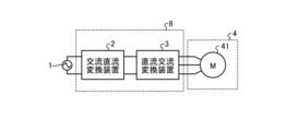
- This disclosure relates to an AC/DC converter that converts AC power into desired DC power, as well as a rotating machine drive device and a refrigeration cycle application device that are equipped with the AC/DC converter.
- a power factor correction circuit When obtaining DC voltage from an AC power source, it is common to use a power factor correction circuit.
- a power factor correction circuit has the functions of controlling the bus voltage at a constant level and controlling the power supply current so as to comply with harmonic standards.
- a power factor correction circuit and one of its control methods is a method in which switching is performed at least once per half cycle of the power supply voltage, which is the voltage of the AC power supply, and has the characteristic of being able to control the bus voltage to be lower than the peak value of the power supply voltage.
- the operating circuit switches from a boost chopper to a capacitor-input type diode rectifier, which creates the problem of distorting the power supply current.
- Patent Document 1 determines whether the combination of reactor capacity and switching timing complies with harmonic standards by repeating the design for each load power.
- Patent Document 1 is a method of checking whether or not compliance with harmonic standard values can be achieved through repeated trials, which poses the problem that the number of trials increases exponentially as the number of pulses increases.
- the AC-DC converter disclosed herein has the effect of shortening the time required for design work and complying with harmonic standards while suppressing an increase in the computational load.
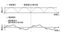
- FIG. 6 is a diagram showing an example of operating waveforms when the AC-DC converter 2 shown in FIG. 2 is operated with a fundamental power factor of 1.
- the waveform of the absolute value of the power supply voltage is shown by a dashed line
- the waveform of the bus voltage is shown by a solid line.
- the waveform of the power supply current is shown by a solid line
- the waveform of the fundamental wave component (command value) of the power supply current is shown by a dashed line.
- V s is the effective value of the power supply voltage v s
- ⁇ is the angular frequency of the power supply voltage v s .
- Section 1 0 ⁇ (0 ⁇ t ⁇ t1)
- Section 2 ⁇ (t1 ⁇ t ⁇ t3)
- Section 3 ⁇ 180° (t3 ⁇ t ⁇ T/2)
- the power supply current iL2 flowing in section 2 can be expressed by the following formula (8).
- phase ⁇ means the amount of phase shift in phase shift control. Therefore, in the following explanation, "phase ⁇ " will also be written as "phase shift amount ⁇ " where appropriate. Note that in this paper, the phase shift amount ⁇ is treated as meaning a lag phase, so a minus sign is added to the right-hand side of equation (19).
- the calculation of the phase shift amount ⁇ requires the value of the conduction start phase ⁇ , which is the intersection point between the power supply voltage v s and the bus voltage V dc , and the value of the conduction end phase ⁇ , where the power supply current i L becomes zero.
- the conduction start phase ⁇ can be obtained by the above-mentioned equation (3).
- FIG. 7 is a diagram for explaining the Newton method used in the first embodiment.
- an arbitrary function f(x) and a straight line f'(x) which is a tangent to the function f(x) at coordinates ( x1 , f( x1 )) are shown on an xy plane.
- the point where the straight line f'(x) intersects with the x-axis is represented as " x2 ".
- the difference between x1 and x2 i.e., the difference in the x-axis direction, is represented as " ⁇ x"
- the difference in the y-axis direction at the y-coordinate f( x1 ) is represented as " ⁇ y”.
- the differential coefficient at the coordinates ( x1 , f( x1 )) is f'( x1 )
- the relationship of the following formula (20) is established.
- the above formula (23) is an approximation obtained by calculating the conduction end phase ⁇ for a plurality of output voltage values using Newton's method and deriving an approximation from the relationship between the conduction end phase ⁇ and the voltage ratio Vr .
- FIG. 8 is a diagram showing an example of a curve showing the conduction end phase ⁇ used in the phase shift control of the first embodiment.
- the above formula (23) is insensitive to the frequency of the power supply voltage v s and the inductance L of the reactor 212. Therefore, the formula (23) can be used even when the circuit parameters of the AC-DC converter 2 are changed.
- the above formula (22) does not include the angular frequency ⁇ and the inductance L.
- the angular frequency ⁇ and the inductance L are also not included in the formula (3) representing the conduction start phase ⁇ . From this, it can be said that the phase at which the power supply current iL becomes zero does not depend on the frequency of the power supply voltage v s and the inductance L of the reactor 212, but is a physical quantity that has the property of changing depending on the voltage ratio Vr .
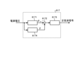
- the phase shift amount calculator 6174 calculates the phase shift amount ⁇ based on the above equation (19).
- the phase shift amount calculator 6174 outputs the calculated phase shift amount ⁇ to the subtractor 6172. If the sine wave phase output from the PLL calculator 6171 is represented as ⁇ vs , then " ⁇ vs - ⁇ " is input to the sine wave calculator 6173. Therefore, the sine wave calculator 6173 outputs a sine wave signal f expressed by the following equation (24).
- the sine wave signal f is a signal that excites the first current command value, and shifting the phase of the sine wave signal f also shifts the phase of the power supply current iL .
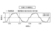
- FIG. 9 is a diagram showing an example of operating waveforms when phase shift control is not performed on the AC-DC converter 2 shown in FIG. 2.
- FIG. 10 is a diagram showing an example of operating waveforms when phase shift control is performed on the AC-DC converter 2 shown in FIG. 2.
- the waveform of the power supply current is shown by a solid line
- the waveform of the fundamental wave component (command value) of the power supply current is shown by a dashed line.
- the power factor of the waveform of the power supply current shown in FIG. 9 is "0.988”
- the THD (Total Harmonic Distortion) of the waveform of the power supply current is "15.6%”.
- the power factor of the waveform of the power supply current shown in FIG. 10 is "0.918", and the THD of the waveform of the power supply current is "4.60%”.
- THD is defined by the following equation (25).
- I1 is the fundamental wave component of the power supply current iL
- I2 , I3 , I4 , I5 , . . . are second or higher harmonic components in the power supply current iL .
- the power factor value in FIG. 9 is closer to 1.
- the power current iL does not follow the fundamental wave component of the power current iL , and the waveform of the power current iL is distorted.
- the waveform of the power current iL itself changes in agreement with the waveform of the fundamental wave component of the power current iL . That is, if the AC-DC converter 2 is operated using the phase shift control of this paper, it is possible to control the power current iL to be sinusoidal. Therefore, if the phase shift control of this paper is used, it is possible to operate the AC-DC converter 2 so as to comply with the harmonic standard value without relying on trial and error adjustments that confirm whether or not it is possible to comply with the harmonic standard value by repeated trials.
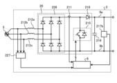
- the AC-DC converter according to the first embodiment includes a rectifier circuit that rectifies the power supply voltage applied from the AC power supply, a capacitor that smoothes the output voltage of the rectifier circuit, a reactor that is disposed closer to the AC power supply side than the capacitor, and a current detection unit that detects the power supply current flowing between the AC power supply and the rectifier circuit.
- the rectifier circuit has at least one switching element that is disposed closer to the AC power supply side than the capacitor. When generating a switching signal for controlling the switching element, the control unit generates the switching signal so as to change the phase of the power supply current. According to the AC-DC converter according to the first embodiment, it is possible to control the power supply current to a sinusoidal wave shape.
- phase shift amount calculator 6174 calculates the phase shift amount ⁇ based on the power supply voltage v s .
- phase shift amount calculator 6174 calculates the THD defined by the following equation (26) by expanding the power supply voltage v s into a Fourier series.
- Embodiment 3 a different example of the AC-DC converter 2 including the control unit 6 described in the first or second embodiment will be described.
- Components having the same or equivalent functions as those of the AC-DC converter 2 described in the first and second embodiments are denoted by the same reference numerals, and description of the overlapping contents will be omitted.
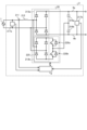
- FIG. 12 is a diagram showing an example of the configuration of an AC-DC converter 2 according to embodiment 3.
- the rectifier circuit 20 is composed of a single-phase H-bridge cell having four switching elements 220a, 220b, 220c, and 220d. Note that the configuration and operation of the rectifier circuit 20 shown in FIG. 12 are publicly known, and further explanation will be omitted here.
- the control unit 6 generates switching signals for the four switching elements 220a, 220b, 220c, and 220d using the control method described in embodiment 1 or embodiment 2 to drive them.
- the AC-DC converter 2 shown in FIG. 12 can achieve the same effects as those of embodiment 1 or embodiment 2.
- the switching elements 220a, 220b, 220c, and 220d are shown as IGBTs, but any elements capable of switching operation may be used.
- the AC-DC converter 2 shown in FIG. 12 is configured as a closed loop, but it may also be configured as an open loop. When the AC-DC converter 2 is configured as an open loop, the detection values of the voltage detectors 217a and 217b and the current detector 211 do not need to be used.
- Embodiment 4 a different example of the AC-DC converter 2 including the control unit 6 described in the first or second embodiment will be described. Components having the same or equivalent functions as those of the AC-DC converter 2 described in the first or second embodiment will be denoted by the same reference numerals, and the description of the overlapping contents will be omitted.
- the control unit 6 generates switching signals for the two switching elements 220c, 220d using the control method described in embodiment 1 or embodiment 2 to drive them. This allows the AC-DC converter 2 shown in FIG. 13 to achieve the same effects as those of embodiment 1 or embodiment 2.
- the switching elements 220c and 220d are shown as IGBTs, but any elements capable of switching operation may be used.
- the AC-DC converter 2 shown in FIG. 13 is configured as a closed loop, but it may also be configured as an open loop. When the AC-DC converter 2 is configured as an open loop, the detection values of the voltage detectors 217a and 217b and the current detector 211 do not need to be used.
- Embodiment 5 a different example of the AC-DC converter 2 including the control unit 6 described in the first or second embodiment will be described. Components having the same or equivalent functions as those of the AC-DC converter 2 described in the first or second embodiment will be denoted by the same reference numerals, and the description of the overlapping contents will be omitted.
- the switching elements 220b and 220d are shown as IGBTs, but any elements capable of switching operation may be used.
- the AC-DC converter 2 shown in FIG. 14 is configured as a closed loop, but it may also be configured as an open loop. When the AC-DC converter 2 is configured as an open loop, the detection values of the voltage detectors 217a and 217b and the current detector 211 do not need to be used.
- Embodiment 6 a different example of the AC-DC converter 2 including the control unit 6 described in the first or second embodiment will be described. Components having the same or equivalent functions as those of the AC-DC converter 2 described in the first or second embodiment will be denoted by the same reference numerals, and the description of the overlapping contents will be omitted.
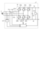
- FIG. 15 is a diagram showing an example of the configuration of an AC-DC converter 2 according to embodiment 6.
- the rectifier circuit 20 is composed of a single-phase H-bridge cell including two diodes 218a and 218b, four switching elements 220a, 220b, 220c, and 220d, a capacitor 216b, and a voltage detector 217c.
- the voltage detector 217c may be provided outside the rectifier circuit 20.
- one leg is composed of a series circuit of diodes 218a and 218b, and the other leg is composed of a series circuit of switching elements 220a, 220b, 220c, and 220d.
- the capacitor 216b is connected between the connection point of the switching elements 220a and 220b and the connection point of the switching elements 220c and 220d.
- the voltage detection unit 217c detects the voltage of the capacitor 216b and outputs the detection value to the control unit 6.
- the control unit 6 generates a switching signal for controlling the switching elements 220a, 220b, 220c, and 220d based on the detection values of the voltage detection units 217a, 217b, and 217c and the current detection unit 211.
- the configuration and operation of the rectifier circuit 20 shown in FIG. 15 are publicly known, and further description will be omitted here.
- the control unit 6 generates switching signals for the four switching elements 220a, 220b, 220c, and 220d using the control method described in embodiment 1 or embodiment 2 to drive them.
- the AC-DC converter 2 shown in FIG. 15 can achieve the same effects as those of embodiment 1 or embodiment 2.
- the switching elements 220a, 220b, 220c, and 220d are shown as IGBTs, but any elements capable of switching operation may be used.
- the AC-DC converter 2 shown in FIG. 15 is configured as a closed loop, but it may also be configured as an open loop. When the AC-DC converter 2 is configured as an open loop, the detection values of the voltage detectors 217a, 217b, and 217c and the current detector 211 do not need to be used.
- Embodiment 7 a different example of the AC-DC converter 2 including the control unit 6 described in the first or second embodiment will be described. Components having the same or equivalent functions as those of the AC-DC converter 2 described in the first or second embodiment will be denoted by the same reference numerals, and the description of the overlapping contents will be omitted.
- FIG. 16 is a diagram showing an example of the configuration of an AC-DC converter 2 according to embodiment 7.
- the rectifier circuit 20 is composed of a single-phase H-bridge cell 221 and a switching cell 222.
- the single-phase H-bridge cell 221 includes two diodes 218a and 218c and two switching elements 220b and 220d.
- the switching cell 222 includes four switching elements 220e, 220f, 220g, and 220h, a capacitor 216c, and a voltage detection unit 217c.
- the voltage detection unit 217c may be provided outside the switching cell 222.
- diodes 218a and 218c are arranged in the upper arms of the two legs, and switching elements 220b and 220d are arranged in the lower arms of the two legs.
- switching cell 222 shown in FIG. 16 four switching elements 220e, 220f, 220g, and 220h are bridge-connected.
- the capacitor 216c is connected in parallel to the first leg consisting of the switching elements 220e and 220f and the second leg consisting of the switching elements 220g and 220h.
- the voltage detection unit 217c detects the voltage of the capacitor 216c and outputs the detection value to the control unit 6.
- the control unit 6 generates switching signals for controlling the switching elements 220b, 220d, 220e, 220f, 220g, and 220h based on the detection values of the voltage detection units 217a, 217b, and 217c and the current detection unit 211. Note that the configuration and operation of the rectifier circuit 20 shown in FIG. 16 are publicly known, and further explanation will be omitted here.
- the control unit 6 generates switching signals for the six switching elements 220b, 220d, 220e, 220f, 220g, and 220h using the control method described in embodiment 1 or embodiment 2 to drive them.
- the AC-DC converter 2 shown in FIG. 16 can achieve the same effects as those of embodiment 1 or embodiment 2.
- switching elements 220b, 220d, 220e, 220f, 220g, and 220h are shown as IGBTs, but any elements capable of switching operation may be used.
- the AC-DC converter 2 shown in FIG. 16 is configured as a closed loop, it may also be configured as an open loop. When the AC-DC converter 2 is configured as an open loop, the detection values of voltage detectors 217a, 217b, and 217c and current detector 211 do not need to be used.
- Embodiment 8 In the eighth embodiment, a different example of the AC-DC converter 2 including the control unit 6 described in the first or second embodiment will be described. Components having the same or equivalent functions as those of the AC-DC converter 2 described in the first and second embodiments are denoted by the same reference numerals, and description of the overlapping contents will be omitted.
- FIG. 17 is a diagram showing an example of the configuration of an AC-DC converter 2 according to embodiment 8.
- the rectifier circuit 20 is composed of a single-phase diode bridge cell 213a and a switching cell 225.
- the switching cell 225 includes a single-phase diode bridge cell 213b and a series circuit made up of two switching elements 220a and 220b.
- the series circuit is connected in parallel to the single-phase diode bridge cell 213b.
- the capacitor 216 in FIG. 2 is replaced with two capacitors 216a and 216b connected in series.
- the series-connected capacitors 216a and 216b are connected between the DC buses 9a and 9b.
- the control unit 6 generates switching signals for controlling the switching elements 220a and 220b based on the detection values of the voltage detection units 217a and 217b and the current detection unit 211. Note that the configuration and operation of the rectifier circuit 20 shown in FIG. 17 are publicly known, and further explanation will be omitted here.
- the control unit 6 generates switching signals for the two switching elements 220a and 220b using the control method described in embodiment 1 or embodiment 2 to drive them. This allows the AC-DC converter 2 shown in FIG. 17 to achieve the same effects as those of embodiment 1 or embodiment 2.
- Embodiment 9 a different example of the AC-DC converter 2 including the control unit 6 described in the first or second embodiment will be described. Components having the same or equivalent functions as those of the AC-DC converter 2 described in the first or second embodiment will be denoted by the same reference numerals, and the description of the overlapping contents will be omitted.
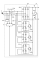
- FIG. 18 is a diagram showing an example of the configuration of an AC-DC converter 2 according to embodiment 9.
- a single-phase AC power source 1 is shown, but in FIG. 18, this is changed to a three-phase AC power source 5.
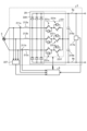
- the rectifier circuit 20 is composed of a three-phase full-bridge cell 226 having six switching elements 220a, 220b, 220c, 220d, 220e, 220f.
- Reactors 212a, 212b, 212c are inserted in each phase between the three-phase AC power source 5 and the rectifier circuit 20, and current detectors 211a, 211b are arranged in any two of the three phases.
- Embodiment 10 In the tenth embodiment, a different example of the AC-DC converter 2 including the control unit 6 described in the first or second embodiment will be described. Components having the same or equivalent functions as those of the AC-DC converter 2 described in the first, second, and ninth embodiments are denoted by the same reference numerals, and description of the overlapping contents will be omitted.
- the rectifier circuit 20 is composed of a three-phase diode bridge cell 228 and a three-phase simplified PAM cell 229.
- the three-phase diode bridge cell 228 has six diodes that are fully bridge-connected.
- the three-phase simplified PAM cell 229 has single-phase diode bridge cells 213a, 213b, 213c and switching elements 215a, 215b, 215c that are connected in parallel to each of the single-phase diode bridge cells 213a, 213b, 213c.
- the switching elements 215a, 215b, and 215c are shown as IGBTs, but any elements capable of switching operation may be used.
- the AC-DC converter 2 shown in FIG. 20 is configured as a closed loop, but it may also be configured as an open loop. When the AC-DC converter 2 is configured as an open loop, the detection values of the voltage detectors 227 and 217b and the current detectors 211a and 211b do not need to be used.
- the control according to embodiment 11 may be performed on ⁇ coordinates or on three-phase coordinates.
Landscapes
- Engineering & Computer Science (AREA)
- Power Engineering (AREA)
- Rectifiers (AREA)
Priority Applications (2)
| Application Number | Priority Date | Filing Date | Title |
|---|---|---|---|
| PCT/JP2023/047278 WO2025141867A1 (ja) | 2023-12-28 | 2023-12-28 | 交流直流変換装置、回転機駆動装置及び冷凍サイクル適用機器 |
| JP2025566163A JPWO2025141867A1 (https=) | 2023-12-28 | 2023-12-28 |
Applications Claiming Priority (1)
| Application Number | Priority Date | Filing Date | Title |
|---|---|---|---|
| PCT/JP2023/047278 WO2025141867A1 (ja) | 2023-12-28 | 2023-12-28 | 交流直流変換装置、回転機駆動装置及び冷凍サイクル適用機器 |
Publications (1)
| Publication Number | Publication Date |
|---|---|
| WO2025141867A1 true WO2025141867A1 (ja) | 2025-07-03 |
Family
ID=96217184
Family Applications (1)
| Application Number | Title | Priority Date | Filing Date |
|---|---|---|---|
| PCT/JP2023/047278 Pending WO2025141867A1 (ja) | 2023-12-28 | 2023-12-28 | 交流直流変換装置、回転機駆動装置及び冷凍サイクル適用機器 |
Country Status (2)
| Country | Link |
|---|---|
| JP (1) | JPWO2025141867A1 (https=) |
| WO (1) | WO2025141867A1 (https=) |
Citations (3)
| Publication number | Priority date | Publication date | Assignee | Title |
|---|---|---|---|---|
| JP2011125147A (ja) * | 2009-12-11 | 2011-06-23 | Hitachi Ltd | 電源回路及びそれを用いたモータ駆動装置並びに冷凍機器 |
| JP2016144323A (ja) * | 2015-02-03 | 2016-08-08 | ジョンソンコントロールズ ヒタチ エア コンディショニング テクノロジー(ホンコン)リミテッド | 直流電源装置およびこれを用いた空気調和機 |
| JP6151034B2 (ja) * | 2013-01-31 | 2017-06-21 | 三菱重工業株式会社 | コンバータ装置及び空気調和機 |
-
2023
- 2023-12-28 WO PCT/JP2023/047278 patent/WO2025141867A1/ja active Pending
- 2023-12-28 JP JP2025566163A patent/JPWO2025141867A1/ja active Pending
Patent Citations (3)
| Publication number | Priority date | Publication date | Assignee | Title |
|---|---|---|---|---|
| JP2011125147A (ja) * | 2009-12-11 | 2011-06-23 | Hitachi Ltd | 電源回路及びそれを用いたモータ駆動装置並びに冷凍機器 |
| JP6151034B2 (ja) * | 2013-01-31 | 2017-06-21 | 三菱重工業株式会社 | コンバータ装置及び空気調和機 |
| JP2016144323A (ja) * | 2015-02-03 | 2016-08-08 | ジョンソンコントロールズ ヒタチ エア コンディショニング テクノロジー(ホンコン)リミテッド | 直流電源装置およびこれを用いた空気調和機 |
Also Published As
| Publication number | Publication date |
|---|---|
| JPWO2025141867A1 (https=) | 2025-07-03 |
Similar Documents
| Publication | Publication Date | Title |
|---|---|---|
| EP3358732B1 (en) | Power conversion device and air-conditioning device using same | |
| JP7459308B2 (ja) | 電力変換装置、モータ駆動装置及び冷凍サイクル適用機器 | |
| WO2016035209A1 (ja) | 電力変換装置及び冷凍サイクル装置 | |
| CN117578903A (zh) | 双有源桥变换器的控制方法、功率变换装置及储能设备 | |
| JP7507894B2 (ja) | 電力変換装置、モータ駆動装置及び冷凍サイクル適用機器 | |
| WO2025141867A1 (ja) | 交流直流変換装置、回転機駆動装置及び冷凍サイクル適用機器 | |
| US20250219559A1 (en) | Power conversion apparatus, motor drive unit, and refrigeration cycle application apparatus | |
| JP7625158B1 (ja) | 交流直流変換装置、回転機駆動装置及び冷凍サイクル適用機器 | |
| EP3419158B1 (en) | Power conversion device and air conditioning device using same | |
| JP7603907B1 (ja) | 交流直流変換装置、回転機駆動装置及び冷凍サイクル適用機器 | |
| JP6805212B2 (ja) | 3組巻線構造モータの駆動装置及び空気調和機 | |
| WO2025141866A1 (ja) | 交流直流変換装置、回転機駆動装置及び冷凍サイクル適用機器 | |
| WO2025141865A1 (ja) | 交流直流変換装置、回転機駆動装置及び冷凍サイクル適用機器 | |
| JP7603906B1 (ja) | 交流直流変換装置、回転機駆動装置及び冷凍サイクル適用機器 | |
| WO2025141870A1 (ja) | 交流直流変換装置、回転機駆動装置及び冷凍サイクル適用機器 | |
| US20240396465A1 (en) | Power conversion device, motor drive device, and refrigeration-cycle application apparatus | |
| WO2025141871A1 (ja) | 交流直流変換装置、回転機駆動装置及び冷凍サイクル適用機器 | |
| WO2025141872A1 (ja) | 交流直流変換装置、回転機駆動装置及び冷凍サイクル適用機器 | |
| JP7551042B1 (ja) | アクティブフィルタ装置、電力変換装置、冷凍サイクル装置及びアクティブフィルタ装置の制御方法 | |
| WO2025141868A1 (ja) | 交流直流変換装置、回転機駆動装置及び冷凍サイクル適用機器 | |
| WO2024190369A1 (ja) | アクティブフィルタ装置、電力変換装置、冷凍サイクル装置及びアクティブフィルタ装置の制御方法 | |
| KR20070077631A (ko) | 역률 보상 기능이 구비된 공기조화기 | |
| JP7183445B2 (ja) | 電力変換装置 | |
| WO2025004328A1 (ja) | 電力変換装置および冷凍サイクル適用機器 | |
| JP6486488B2 (ja) | 電力変換装置、および、それを備えた冷凍サイクル装置 |
Legal Events
| Date | Code | Title | Description |
|---|---|---|---|
| 121 | Ep: the epo has been informed by wipo that ep was designated in this application |
Ref document number: 23963212 Country of ref document: EP Kind code of ref document: A1 |
|
| ENP | Entry into the national phase |
Ref document number: 2025566163 Country of ref document: JP Kind code of ref document: A |
|
| WWE | Wipo information: entry into national phase |
Ref document number: 2025566163 Country of ref document: JP |