WO2025141865A1 - 交流直流変換装置、回転機駆動装置及び冷凍サイクル適用機器 - Google Patents
交流直流変換装置、回転機駆動装置及び冷凍サイクル適用機器 Download PDFInfo
- Publication number
- WO2025141865A1 WO2025141865A1 PCT/JP2023/047276 JP2023047276W WO2025141865A1 WO 2025141865 A1 WO2025141865 A1 WO 2025141865A1 JP 2023047276 W JP2023047276 W JP 2023047276W WO 2025141865 A1 WO2025141865 A1 WO 2025141865A1
- Authority
- WO
- WIPO (PCT)
- Prior art keywords
- voltage
- current
- power supply
- controller
- switching
- Prior art date
- Legal status (The legal status is an assumption and is not a legal conclusion. Google has not performed a legal analysis and makes no representation as to the accuracy of the status listed.)
- Pending
Links
Images













Classifications
-
- H—ELECTRICITY
- H02—GENERATION; CONVERSION OR DISTRIBUTION OF ELECTRIC POWER
- H02M—APPARATUS FOR CONVERSION BETWEEN AC AND AC, BETWEEN AC AND DC, OR BETWEEN DC AND DC, AND FOR USE WITH MAINS OR SIMILAR POWER SUPPLY SYSTEMS; CONVERSION OF DC OR AC INPUT POWER INTO SURGE OUTPUT POWER; CONTROL OR REGULATION THEREOF
- H02M7/00—Conversion of AC power input into DC power output; Conversion of DC power input into AC power output
- H02M7/02—Conversion of AC power input into DC power output without possibility of reversal
- H02M7/04—Conversion of AC power input into DC power output without possibility of reversal by static converters
- H02M7/12—Conversion of AC power input into DC power output without possibility of reversal by static converters using discharge tubes with control electrode or semiconductor devices with control electrode
Definitions
- This disclosure relates to an AC/DC converter that converts AC power into desired DC power, as well as a rotating machine drive device and a refrigeration cycle application device that are equipped with the AC/DC converter.
- a converter circuit When obtaining DC voltage from an AC power source, a converter circuit is generally used.
- the converter circuit has the functions of controlling the bus voltage to a constant value and controlling the power supply current so as to comply with harmonic standards.
- the converter circuit and one of its control methods is a method in which switching is performed at least once per half cycle of the power supply voltage, which is the voltage of the AC power supply, and has the characteristic of being able to control the bus voltage to be lower than the peak value of the power supply voltage.
- the operating circuit switches from a boost chopper to a capacitor-input type diode rectifier, which creates the issue of distorting the power supply current.
- Patent Document 1 determines whether the combination of reactor capacity and switching timing complies with harmonic standards by repeating the design for each load power.
- Patent Document 1 is a method for checking whether or not compliance with harmonic standards can be achieved through repeated trials, which poses the problem that the number of trials increases exponentially as the number of pulses increases.
- the present disclosure has been made in consideration of the above, and aims to obtain an AC/DC conversion device that can comply with harmonic standards while shortening the time required for design work and suppressing an increase in the computational load.
- the AC-DC conversion device includes a rectifier circuit, a capacitor, a reactor, and a control unit.
- the rectifier circuit has at least one switching element and rectifies the power supply voltage applied from the AC power supply.
- the capacitor is connected to the DC bus and smoothes the output voltage of the rectifier circuit.
- the reactor is arranged closer to the AC power supply than the capacitor, and the switching element is arranged closer to the AC power supply than the capacitor.
- the control unit has a repetitive controller that reduces harmonic components contained in the power supply current flowing between the AC power supply and the rectifier circuit, and when generating a switching signal for controlling the switching element, generates the switching signal so that the harmonic components contained in the power supply current comply with the harmonic standard value of the power supply current.
- the AC-DC converter disclosed herein has the effect of shortening the time required for design work and complying with harmonic standards while suppressing an increase in the computational load.
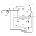
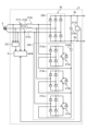
- FIG. 1 is a block diagram showing a configuration example of a rotary machine driving device according to a first embodiment; A circuit diagram showing a configuration example of an AC-DC converter according to a first embodiment.
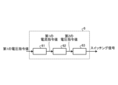
- FIG. 1 is a block diagram showing a configuration example of a control unit according to a first embodiment;
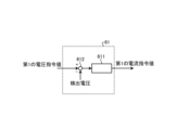
- FIG. 1 is a block diagram showing a configuration example of a voltage control unit according to a first embodiment;
- FIG. 1 is a block diagram showing a configuration example of a current control unit according to a first embodiment;
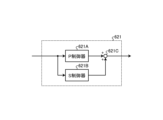
- FIG. 6 is a block diagram showing a configuration example in which the current controller shown in FIG. 5 is configured as a PS controller.
- FIG. 6 is a block diagram showing a configuration example in which a target value filter is introduced into the current control unit shown in FIG.
- FIG. 1 is a block diagram showing a configuration example of a rotary machine driving device according to a first embodiment;
- FIG. 8 is a block diagram for explaining a transfer function of a current control system in an AC-DC converter including the current control unit shown in FIG.
- FIG. 1 is a block diagram showing a configuration example of a switching signal generating unit according to a first embodiment
- FIG. 8 is a diagram showing an example of the operation waveforms of a power supply voltage, a bus voltage, and a power supply current when PI control is applied to the current controller shown in FIG.
- FIG. 8 is a diagram showing an example of the operation waveforms of a power supply voltage, a bus voltage, and a power supply current when PS control is applied to the current controller shown in FIG.
- FIG. 6 is a block diagram showing a first configuration example in which the current controller shown in FIG. 5 is configured with an R controller and a PS controller.
- FIG. 11 is a diagram showing example operating waveforms of the power supply voltage, bus voltage, and power supply current when PS control is applied to the current controller 621 shown in FIG. 7.
- the upper part of FIG. 11 shows the waveforms of the absolute values of the bus voltage and power supply voltage
- the middle part of FIG. 11 shows the waveforms of the detected power supply current, the fundamental wave component of the detected power supply current, and the power supply current command value.
- the lower part of FIG. 11 shows a switching signal for controlling the switching element 215.
- the fundamental wave component of the detected power supply current is almost equal to the power supply current command value.
- the fundamental wave of the detected power supply current can track the power supply current command value even under conditions where the bus voltage is equal to or below the peak value of the absolute value of the power supply voltage.
- Figure 11 shows the results for operating conditions where the bus voltage is equal to or below the peak value of the absolute value of the power supply voltage, but it goes without saying that the fundamental wave of the detected power supply current will track the power supply current command value even under operating conditions where the bus voltage exceeds the peak value of the absolute value of the power supply voltage.
- the control method of the first embodiment proposes using an R (Repetitive) controller in addition to the PS controller.
- T in the above equation (9) represents the dead time in the dead time controller 621D2.
- R control is one of the techniques for reducing harmonics using dead time elements.
- the advantage of R control compared to other harmonic reduction techniques is that a single R controller 621D can reduce multiple harmonics.
- the key point of the technique of embodiment 1 using R control is that control of the power supply frequency component, which is the fundamental wave component, i.e., the primary component of the power supply frequency, is performed by the PS controller consisting of the P controller 621A, S controller 621B, and adder 621C, and harmonic components other than the fundamental wave component are reduced by the R controller 621D.
- this technique of separating the controls realizes control that complies with power supply harmonic standards while suppressing an increase in the amount of calculations.
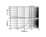
- FIG. 17 is a Bode diagram showing the transfer characteristics of a controller in which the R controller 621D shown in FIG. 16 is applied to the current controller 621 shown in FIG. 12.
- the settings for the dead time T and the like are the same as in FIG. 15.
- the gain diagram in Figure 17 shows that the gain peak in the high frequency range is suppressed. Such characteristics are obtained by applying the low-pass filter 621D3.
- the cutoff frequency that determines the characteristics of the low-pass filter 621D3 can be determined from the harmonic order to be reduced and the response constraints imposed by the control period.
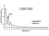
- IEC 61000-3-2 Class A The current harmonics standard used in Figures 18 and 19 is IEC 61000-3-2 Class A. Note that IEC 61000-3-2 Class A is an example of a current harmonics standard, and is not limited to this standard.
- FIG. 18 shows that, of the low-order harmonics from 2nd to 40th, the 5th harmonic component does not meet the standard value.
- another S controller may be configured to be connected in parallel to P controller 621A and S controller 621B.
- the other S controller referred to here is an S controller configured to contribute to reducing the 5th harmonic component.
- the dashed waveform is lower than the solid waveform for the 2nd to 40th orders, and all low-order harmonics from the 2nd to 40th orders meet the standard values. Therefore, when comparing the case where both PS control and R control are applied to the current control unit 62 in FIG. 7 with the case where only PS control is applied, it can be said that the former is easier to control so that the low-order harmonics meet the harmonic standard values of the power supply current.
- Figures 18 and 19 show an example of harmonic components during rated operation, but it goes without saying that the effect of suppressing harmonic components using the method of embodiment 1 can be obtained even during times other than rated operation.
- the R controller 621D operates to reduce harmonic components other than the fundamental component contained in the power supply current.
- the R controller 621D shown in FIG. 20 may be used instead of the R controller 621D shown in FIG. 13.
- FIG. 20 is a block diagram showing a third configuration example of the R controller 621D shown in FIG. 12.
- a band elimination filter 621D4 is inserted in front of the dead time controller 621D2 in the configuration of the R controller 621D shown in FIG. 13.
- the band elimination filter 621D4 operates to block the passage of the fundamental component input to the dead time controller 621D2, so the fundamental component input to the adder 621D1 is also reduced. This makes it possible to reduce the control amount by which the fundamental component is reduced by the R controller 621D compared to the R controller 621D shown in FIG. 13, making it possible to prevent a decrease in the original control performance.
- the AC-DC converter includes a rectifier circuit that rectifies the power supply voltage applied from the AC power supply, a capacitor that smoothes the output voltage of the rectifier circuit, and a reactor that is arranged on the AC power supply side of the capacitor.
- the rectifier circuit has at least one switching element that is arranged on the AC power supply side of the capacitor.
- the control unit has an R controller that reduces harmonic components contained in the power supply current flowing between the AC power supply and the rectifier circuit, and when generating a switching signal for controlling the switching element, generates a switching signal so that the harmonic components contained in the power supply current comply with the harmonic standard value of the power supply current.
- the AC-DC converter according to the first embodiment it is possible to comply with the harmonic standard without relying on a trial-and-error adjustment method that confirms whether or not compliance with the harmonic standard can be achieved by repeated trials. Furthermore, according to the AC-DC converter according to the first embodiment, even under operating conditions in which the bus voltage exceeds the peak value of the absolute value of the power supply voltage, it is possible to comply with the harmonic standard while improving the input power factor. Furthermore, according to the AC-DC converter of the first embodiment, even if there are many order components to be reduced, the R controller operates to reduce many order components. This eliminates the need to take measures such as increasing the number of S controllers connected in parallel, and makes it possible to comply with harmonic standards while suppressing an increase in the computational load.
- the switching signal generating unit prefferably to generate a switching signal so that the number of switching operations in one power supply voltage cycle when the switching element performs switching operation is at least once and is equal to or less than the carrier frequency normalized by the frequency of the power supply voltage. By generating such a switching signal, it is possible to suppress switching losses in the switching cell.
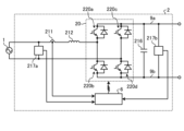
- diodes 218a and 218c are arranged in the upper arms of the two legs, and switching elements 220b and 220d are arranged in the lower arms of the two legs.
- switching cell 222 shown in FIG. 25 four switching elements 220e, 220f, 220g, and 220h are bridge-connected.
- the capacitor 216c is connected in parallel to the first leg consisting of the switching elements 220e and 220f and the second leg consisting of the switching elements 220g and 220h.
- the control unit 6 generates switching signals for the six switching elements 220b, 220d, 220e, 220f, 220g, and 220h using the control method described in embodiment 1 to drive them. This allows the AC-DC converter 2 shown in FIG. 25 to achieve the same effects as in embodiment 1.
- switching elements 220b, 220d, 220e, 220f, 220g, and 220h are shown as IGBTs, but any elements capable of switching operation may be used.
- the AC-DC converter 2 shown in FIG. 25 is configured as a closed loop, it may also be configured as an open loop. When the AC-DC converter 2 is configured as an open loop, the detection values of voltage detectors 217a, 217b, and 217c and current detector 211 do not need to be used.
- Embodiment 7 a different example of the AC-DC converter 2 including the control unit 6 described in the first embodiment will be described. Components having the same or equivalent functions as those of the AC-DC converter 2 described in the first embodiment will be denoted by the same reference numerals, and a description of the overlapping contents will be omitted.
- FIG. 26 is a diagram showing an example of the configuration of an AC-DC converter 2 according to embodiment 7.
- the rectifier circuit 20 is composed of a single-phase diode bridge cell 213a and a switching cell 225.
- the switching cell 225 includes a single-phase diode bridge cell 213b and a series circuit made up of two switching elements 220a and 220b.
- the series circuit is connected in parallel to the single-phase diode bridge cell 213b.
- the capacitor 216 in FIG. 2 is replaced with two capacitors 216a and 216b connected in series.
- the series-connected capacitors 216a and 216b are connected between the DC buses 9a and 9b.
- the control unit 6 generates switching signals for controlling the switching elements 220a and 220b based on the detection values of the voltage detection units 217a and 217b and the current detection unit 211. Note that the configuration and operation of the rectifier circuit 20 shown in FIG. 26 are publicly known, and further description will be omitted here.
- the control unit 6 generates switching signals for the two switching elements 220a and 220b using the control method described in embodiment 1 to drive them. This allows the AC-DC converter 2 shown in FIG. 26 to achieve the same effects as in embodiment 1.
- the switching elements 220a and 220b are shown as IGBTs, but any elements capable of switching operation may be used.
- the AC-DC converter 2 shown in FIG. 26 is configured as a closed loop, but it may also be configured as an open loop. When the AC-DC converter 2 is configured as an open loop, the detection values of the voltage detectors 217a and 217b and the current detector 211 do not need to be used.
- Embodiment 8 In the eighth embodiment, a different example of the AC-DC converter 2 including the control unit 6 described in the first embodiment will be described. Components having the same or equivalent functions as those of the AC-DC converter 2 described in the first embodiment will be denoted by the same reference numerals, and description of the overlapping contents will be omitted.
- FIG. 27 is a diagram showing an example of the configuration of an AC-DC converter 2 according to embodiment 8.
- the rectifier circuit 20 is composed of a three-phase full-bridge cell 226 having six switching elements 220a, 220b, 220c, 220d, 220e, 220f.
- Reactors 212a, 212b, 212c are inserted in each phase between the three-phase AC power source 5 and the rectifier circuit 20, and current detectors 211a, 211b are arranged in any two of the three phases.
- the voltage detection unit 227 detects the voltage of each phase of the three-phase AC power supply 5 and outputs the detection value to the control unit 6.
- the current detection units 211a and 211b detect the current flowing in any two of the three phases and output the detection value to the control unit 6. The current in the remaining phase can be found by calculation inside the control unit 6, taking advantage of the fact that the currents in each phase are three-phase balanced.
- the control unit 6 generates switching signals for controlling the switching elements 220a, 220b, 220c, 220d, 220e, and 220f based on the detection values of the voltage detection units 217b and 227 and the current detection units 211a and 211b. Note that the configuration and operation of the rectifier circuit 20 shown in FIG. 27 are publicly known, and further description will be omitted here.
- the control unit 6 generates switching signals for the six switching elements 220a, 220b, 220c, 220d, 220e, and 220f using the control method described in embodiment 1 to drive them. This allows the AC/DC converter 2 shown in FIG. 27 to achieve the same effects as in embodiment 1.
- the switching elements 220a, 220b, 220c, 220d, 220e, and 220f are shown as IGBTs, but any elements capable of switching operation may be used.
- the AC-DC converter 2 shown in FIG. 27 is configured as a closed loop, but it may also be configured as an open loop. When the AC-DC converter 2 is configured as an open loop, the detection values of the voltage detectors 227 and 217b and the current detectors 211a and 211b do not need to be used.
- the control according to the eighth embodiment may be performed on ⁇ coordinates or on three-phase coordinates.
- Embodiment 9 a different example of the AC-DC converter 2 including the control unit 6 described in the first embodiment will be described. Components having the same or equivalent functions as those of the AC-DC converter 2 described in the first and eighth embodiments will be denoted by the same reference numerals, and description of the overlapping contents will be omitted.
- the rectifier circuit 20 is composed of a three-phase diode bridge cell 228 and a three-phase simplified PAM cell 229.
- the three-phase diode bridge cell 228 has six diodes that are fully bridge-connected.
- the three-phase simplified PAM cell 229 has single-phase diode bridge cells 213a, 213b, 213c and switching elements 215a, 215b, 215c that are connected in parallel to the single-phase diode bridge cells 213a, 213b, 213c, respectively.
- Embodiment 10 In the tenth embodiment, a different example of the AC-DC converter 2 including the control unit 6 described in the first embodiment will be described. Components having the same or equivalent functions as those of the AC-DC converter 2 described in the first, eighth and ninth embodiments will be denoted by the same reference numerals, and description of the overlapping contents will be omitted.
- the control unit 6 generates switching signals for controlling the switching elements 215a, 215b, and 215c based on the detection values of the voltage detection units 227 and 217b and the current detection units 211a and 211b. Note that the configuration and operation of the rectifier circuit 20 shown in FIG. 29 are publicly known, and further description will be omitted here.
- FIG. 31 is a diagram showing an example of the configuration of an AC-DC converter 2 according to embodiment 12.
- the reactors 212a, 212b, and 212c arranged between the three-phase AC power source 5 and the three-phase diode bridge cell 228 in the configuration of the AC-DC converter 2 of FIG. 30 are replaced with a reactor 212.
- the reactor 212 is arranged between the three-phase diode bridge cell 228 and the diode 218. The rest is the same or equivalent to FIG. 30.
- Embodiment 13 In the thirteenth embodiment, a different example of the AC-DC converter 2 including the control unit 6 described in the first embodiment will be described. Components having the same or equivalent functions as those of the AC-DC converter 2 described in the first and eighth embodiments will be denoted by the same reference numerals, and description of the overlapping contents will be omitted.
- FIG. 32 is a diagram showing an example of the configuration of an AC-DC converter 2 according to embodiment 13.
- the rectifier circuit 20 is composed of a three-phase diode bridge cell 228 and a three-phase bidirectional switching cell 231.
- the three-phase bidirectional switching cell 231 has six switching elements 231a, 231b, 231c, 231d, 231e, and 231f.
- the capacitor 216 of FIG. 27 is replaced with two capacitors 216a and 216b connected in series.
- the series-connected capacitors 216a and 216b are connected between the DC buses 9a and 9b.
- the switching elements 231a and 231b, the switching elements 231c and 231d, and the switching elements 231e and 231f are connected in series in pairs. Each series-connected pair is arranged for each phase between the three-phase diode bridge cell 228 and the connection point of the capacitors 216a and 216b. Note that the configuration and operation of the rectifier circuit 20 shown in FIG. 32 are publicly known, and further description here is omitted.
- Embodiment 14 In the fourteenth embodiment, a different example of the AC-DC converter 2 including the control unit 6 described in the first embodiment will be described. Components having the same or equivalent functions as those of the AC-DC converter 2 described in the first embodiment will be denoted by the same reference numerals, and description of the overlapping contents will be omitted.
- FIG. 33 is a diagram showing an example of the configuration of an AC-DC converter 2 according to embodiment 14.
- the rectifier circuit 20 is composed of a single-phase diode bridge cell 213a and an interleave cell 219.
- the interleave cell 219 is a full PAM circuit configuration described in FIG. 12 with two sets of reactor 212, switching element 215, and diode 218.
- the interleave cell 219 includes reactors 2191a and 2191b, diodes 2192a and 2192b, and switching elements 2193a and 2193b.
- the configuration and operation of the rectifier circuit 20 shown in FIG. 33 are publicly known, and further description here is omitted.
- the control unit 6 generates switching signals for the two switching elements 2193a and 2193b using the control method described in embodiment 1 to drive them. This allows the AC-DC converter 2 shown in FIG. 33 to achieve the same effects as in embodiment 1.
- switching elements 2193a and 2193b are shown as IGBTs in FIG. 33, any elements capable of switching operation may be used.
- the AC-DC converter 2 shown in FIG. 33 is configured as a closed loop, it may also be configured as an open loop. When the AC-DC converter 2 is configured as an open loop, the detection values of the voltage detectors 217a and 217b and the current detector 211 do not need to be used.
- the interleaved cells 219 are configured in two stages is shown in FIG. 33, the interleaved cells 219 may also be configured in three or more stages.
- the rectifier circuits 20 shown in the first to fourteenth embodiments may also be configured in an interleaved configuration.
- Embodiment 15. 34 is a diagram showing a configuration example of a refrigeration cycle applied device 900 according to embodiment 15.
- the refrigeration cycle applied device 900 according to embodiment 15 includes the rotating machine drive device 8 described in embodiment 1.
- the refrigeration cycle applied device 900 according to embodiment 15 can be applied to products including a refrigeration cycle, such as air conditioners, refrigerators, freezers, and heat pump water heaters.
- the indoor heat exchanger 906 acts as a condenser to release heat, and the outdoor heat exchanger 910 acts as an evaporator to absorb heat.
- the outdoor heat exchanger 910 acts as a condenser to release heat, and the indoor heat exchanger 906 acts as an evaporator to absorb heat.
- the expansion valve 908 reduces the pressure of the refrigerant and causes it to expand.
Landscapes
- Engineering & Computer Science (AREA)
- Power Engineering (AREA)
- Rectifiers (AREA)
Priority Applications (2)
| Application Number | Priority Date | Filing Date | Title |
|---|---|---|---|
| JP2025566161A JPWO2025141865A1 (https=) | 2023-12-28 | 2023-12-28 | |
| PCT/JP2023/047276 WO2025141865A1 (ja) | 2023-12-28 | 2023-12-28 | 交流直流変換装置、回転機駆動装置及び冷凍サイクル適用機器 |
Applications Claiming Priority (1)
| Application Number | Priority Date | Filing Date | Title |
|---|---|---|---|
| PCT/JP2023/047276 WO2025141865A1 (ja) | 2023-12-28 | 2023-12-28 | 交流直流変換装置、回転機駆動装置及び冷凍サイクル適用機器 |
Publications (1)
| Publication Number | Publication Date |
|---|---|
| WO2025141865A1 true WO2025141865A1 (ja) | 2025-07-03 |
Family
ID=96217182
Family Applications (1)
| Application Number | Title | Priority Date | Filing Date |
|---|---|---|---|
| PCT/JP2023/047276 Pending WO2025141865A1 (ja) | 2023-12-28 | 2023-12-28 | 交流直流変換装置、回転機駆動装置及び冷凍サイクル適用機器 |
Country Status (2)
| Country | Link |
|---|---|
| JP (1) | JPWO2025141865A1 (https=) |
| WO (1) | WO2025141865A1 (https=) |
Citations (7)
| Publication number | Priority date | Publication date | Assignee | Title |
|---|---|---|---|---|
| JPH0720906A (ja) * | 1993-07-06 | 1995-01-24 | Hitachi Ltd | 負帰還制御装置及びそれを用いたシステム |
| JP2012165539A (ja) * | 2011-02-04 | 2012-08-30 | Mitsubishi Electric Corp | 電源変換装置および空気調和機 |
| CN106229991A (zh) * | 2016-09-26 | 2016-12-14 | 国网上海市电力公司 | 一种适用于电网电压出现扰动情况下的Vienna整流器控制方法 |
| KR20180009244A (ko) * | 2016-07-18 | 2018-01-26 | 창원대학교 산학협력단 | 역률 보상 제어 장치 |
| WO2020070814A1 (ja) * | 2018-10-03 | 2020-04-09 | 三菱電機株式会社 | 電力変換器の制御装置及びフィードバック制御装置 |
| CN112019072A (zh) * | 2020-07-09 | 2020-12-01 | 合肥华耀电子工业有限公司 | 一种适用于单相或三相整流器的复合控制器及复合控制方法 |
| JP2022185025A (ja) * | 2020-05-28 | 2022-12-13 | 日立ジョンソンコントロールズ空調株式会社 | 直流電源装置および空気調和機 |
-
2023
- 2023-12-28 WO PCT/JP2023/047276 patent/WO2025141865A1/ja active Pending
- 2023-12-28 JP JP2025566161A patent/JPWO2025141865A1/ja active Pending
Patent Citations (7)
| Publication number | Priority date | Publication date | Assignee | Title |
|---|---|---|---|---|
| JPH0720906A (ja) * | 1993-07-06 | 1995-01-24 | Hitachi Ltd | 負帰還制御装置及びそれを用いたシステム |
| JP2012165539A (ja) * | 2011-02-04 | 2012-08-30 | Mitsubishi Electric Corp | 電源変換装置および空気調和機 |
| KR20180009244A (ko) * | 2016-07-18 | 2018-01-26 | 창원대학교 산학협력단 | 역률 보상 제어 장치 |
| CN106229991A (zh) * | 2016-09-26 | 2016-12-14 | 国网上海市电力公司 | 一种适用于电网电压出现扰动情况下的Vienna整流器控制方法 |
| WO2020070814A1 (ja) * | 2018-10-03 | 2020-04-09 | 三菱電機株式会社 | 電力変換器の制御装置及びフィードバック制御装置 |
| JP2022185025A (ja) * | 2020-05-28 | 2022-12-13 | 日立ジョンソンコントロールズ空調株式会社 | 直流電源装置および空気調和機 |
| CN112019072A (zh) * | 2020-07-09 | 2020-12-01 | 合肥华耀电子工业有限公司 | 一种适用于单相或三相整流器的复合控制器及复合控制方法 |
Also Published As
| Publication number | Publication date |
|---|---|
| JPWO2025141865A1 (https=) | 2025-07-03 |
Similar Documents
| Publication | Publication Date | Title |
|---|---|---|
| US9929670B2 (en) | Power conversion device, motor drive control device equipped with power conversion device, compressor and blower equipped with motor drive control device, and air conditioner equipped with compressor or blower | |
| JP3422218B2 (ja) | コンバータ | |
| WO2016035209A1 (ja) | 電力変換装置及び冷凍サイクル装置 | |
| WO2022091186A1 (ja) | 電力変換装置、モータ駆動装置および冷凍サイクル適用機器 | |
| JP7507894B2 (ja) | 電力変換装置、モータ駆動装置及び冷凍サイクル適用機器 | |
| WO2025141865A1 (ja) | 交流直流変換装置、回転機駆動装置及び冷凍サイクル適用機器 | |
| JP7625158B1 (ja) | 交流直流変換装置、回転機駆動装置及び冷凍サイクル適用機器 | |
| Shin et al. | Active DC-link circuit for single-phase diode rectifier system with small capacitance | |
| Hiraide et al. | Current harmonics reduction method of electrolytic capacitor-less diode rectifier using inverter-controlled IPM motor | |
| Paukner et al. | Dynamic behavior of the PV Grid-connected inverter based on L and LCL filter with active damping control | |
| JP6773169B1 (ja) | 空気調和装置 | |
| WO2025141866A1 (ja) | 交流直流変換装置、回転機駆動装置及び冷凍サイクル適用機器 | |
| Endo et al. | Power electronics technology applied in inverter air conditioners | |
| Osman et al. | Development of active power filter using rectifier boost technique | |
| JP7603906B1 (ja) | 交流直流変換装置、回転機駆動装置及び冷凍サイクル適用機器 | |
| JP6935015B2 (ja) | 高調波電流補償装置および空気調和システム | |
| JPWO2018109805A1 (ja) | 高調波電流補償装置および空気調和システム | |
| KR101905480B1 (ko) | 모터 구동장치 및 이를 구비하는 공기조화기 | |
| WO2025141870A1 (ja) | 交流直流変換装置、回転機駆動装置及び冷凍サイクル適用機器 | |
| WO2025141867A1 (ja) | 交流直流変換装置、回転機駆動装置及び冷凍サイクル適用機器 | |
| JP7603907B1 (ja) | 交流直流変換装置、回転機駆動装置及び冷凍サイクル適用機器 | |
| WO2025141868A1 (ja) | 交流直流変換装置、回転機駆動装置及び冷凍サイクル適用機器 | |
| WO2025141871A1 (ja) | 交流直流変換装置、回転機駆動装置及び冷凍サイクル適用機器 | |
| Zare et al. | A multi-pulse front-end rectifier system with electronic phase-shifting for harmonic mitigation in motor drive applications | |
| WO2022149213A1 (ja) | 電力変換装置、モータ駆動装置および冷凍サイクル適用機器 |
Legal Events
| Date | Code | Title | Description |
|---|---|---|---|
| 121 | Ep: the epo has been informed by wipo that ep was designated in this application |
Ref document number: 23963210 Country of ref document: EP Kind code of ref document: A1 |
|
| ENP | Entry into the national phase |
Ref document number: 2025566161 Country of ref document: JP Kind code of ref document: A |
|
| WWE | Wipo information: entry into national phase |
Ref document number: 2025566161 Country of ref document: JP |