WO2025141634A1 - セキュリティリレー - Google Patents
セキュリティリレー Download PDFInfo
- Publication number
- WO2025141634A1 WO2025141634A1 PCT/JP2023/046369 JP2023046369W WO2025141634A1 WO 2025141634 A1 WO2025141634 A1 WO 2025141634A1 JP 2023046369 W JP2023046369 W JP 2023046369W WO 2025141634 A1 WO2025141634 A1 WO 2025141634A1
- Authority
- WO
- WIPO (PCT)
- Prior art keywords
- unit
- relay
- power supply
- security
- control unit
- Prior art date
- Legal status (The legal status is an assumption and is not a legal conclusion. Google has not performed a legal analysis and makes no representation as to the accuracy of the status listed.)
- Pending
Links
Images


Classifications
-
- H—ELECTRICITY
- H02—GENERATION; CONVERSION OR DISTRIBUTION OF ELECTRIC POWER
- H02J—ELECTRIC POWER NETWORKS; CIRCUIT ARRANGEMENTS OR SYSTEMS FOR SUPPLYING OR DISTRIBUTING ELECTRIC POWER; SYSTEMS FOR STORING ELECTRIC ENERGY
- H02J13/00—Circuit arrangements for providing remote monitoring or remote control of equipment in a power distribution network
- H02J13/18—Circuit arrangements for providing remote monitoring or remote control of equipment in a power distribution network characterised by the remotely-controlled equipment, e.g. converters or transformers
- H02J13/34—Circuit arrangements for providing remote monitoring or remote control of equipment in a power distribution network characterised by the remotely-controlled equipment, e.g. converters or transformers the equipment being switches, relays or circuit breakers
-
- H—ELECTRICITY
- H01—ELECTRIC ELEMENTS
- H01H—ELECTRIC SWITCHES; RELAYS; SELECTORS; EMERGENCY PROTECTIVE DEVICES
- H01H47/00—Circuit arrangements not adapted to a particular application of the relay and designed to obtain desired operating characteristics or to provide energising current
- H01H47/002—Monitoring or fail-safe circuits
-
- H—ELECTRICITY
- H01—ELECTRIC ELEMENTS
- H01H—ELECTRIC SWITCHES; RELAYS; SELECTORS; EMERGENCY PROTECTIVE DEVICES
- H01H47/00—Circuit arrangements not adapted to a particular application of the relay and designed to obtain desired operating characteristics or to provide energising current
- H01H47/22—Circuit arrangements not adapted to a particular application of the relay and designed to obtain desired operating characteristics or to provide energising current for supplying energising current for relay coil
-
- H—ELECTRICITY
- H03—ELECTRONIC CIRCUITRY
- H03K—PULSE TECHNIQUE
- H03K17/00—Electronic switching or gating, i.e. not by contact-making and –breaking
- H03K17/51—Electronic switching or gating, i.e. not by contact-making and –breaking characterised by the components used
- H03K17/56—Electronic switching or gating, i.e. not by contact-making and –breaking characterised by the components used by the use, as active elements, of semiconductor devices
- H03K17/72—Electronic switching or gating, i.e. not by contact-making and –breaking characterised by the components used by the use, as active elements, of semiconductor devices having more than two PN junctions; having more than three electrodes; having more than one electrode connected to the same conductivity region
- H03K17/722—Electronic switching or gating, i.e. not by contact-making and –breaking characterised by the components used by the use, as active elements, of semiconductor devices having more than two PN junctions; having more than three electrodes; having more than one electrode connected to the same conductivity region with galvanic isolation between the control circuit and the output circuit
-
- H—ELECTRICITY
- H03—ELECTRONIC CIRCUITRY
- H03K—PULSE TECHNIQUE
- H03K17/00—Electronic switching or gating, i.e. not by contact-making and –breaking
- H03K17/51—Electronic switching or gating, i.e. not by contact-making and –breaking characterised by the components used
- H03K17/56—Electronic switching or gating, i.e. not by contact-making and –breaking characterised by the components used by the use, as active elements, of semiconductor devices
- H03K17/72—Electronic switching or gating, i.e. not by contact-making and –breaking characterised by the components used by the use, as active elements, of semiconductor devices having more than two PN junctions; having more than three electrodes; having more than one electrode connected to the same conductivity region
- H03K17/722—Electronic switching or gating, i.e. not by contact-making and –breaking characterised by the components used by the use, as active elements, of semiconductor devices having more than two PN junctions; having more than three electrodes; having more than one electrode connected to the same conductivity region with galvanic isolation between the control circuit and the output circuit
- H03K17/723—Electronic switching or gating, i.e. not by contact-making and –breaking characterised by the components used by the use, as active elements, of semiconductor devices having more than two PN junctions; having more than three electrodes; having more than one electrode connected to the same conductivity region with galvanic isolation between the control circuit and the output circuit using transformer coupling
-
- H—ELECTRICITY
- H03—ELECTRONIC CIRCUITRY
- H03K—PULSE TECHNIQUE
- H03K17/00—Electronic switching or gating, i.e. not by contact-making and –breaking
- H03K17/51—Electronic switching or gating, i.e. not by contact-making and –breaking characterised by the components used
- H03K17/78—Electronic switching or gating, i.e. not by contact-making and –breaking characterised by the components used using opto-electronic devices, i.e. light-emitting and photoelectric devices electrically- or optically-coupled
- H03K17/79—Electronic switching or gating, i.e. not by contact-making and –breaking characterised by the components used using opto-electronic devices, i.e. light-emitting and photoelectric devices electrically- or optically-coupled controlling bipolar semiconductor switches with more than two PN-junctions, or more than three electrodes, or more than one electrode connected to the same conductivity region
Definitions
- the present invention relates to a relay, and in particular to a security relay equipped with a security function that allows the flow of current to a connected external circuit to be controlled depending on whether or not an external command to allow the relay to be energized is received.
- a relay is a device that uses the passage of current through one terminal of a device as a trigger to control the flow of current through the other terminals, and is used, for example, to ensure safety when passing large currents and to ensure reliable operation.
- security relays that not only control current flow but also have security functions have also come into existence.
- This technology certainly makes it possible to provide a relay with many functions, but it is difficult to respond to abnormal situations such as unauthorized opening and closing of a contact device, and it is difficult to respond to unauthorized manipulation of an external circuit to which the relay is connected, so it cannot be said to be a sufficient technology from a security standpoint.
- the security function of a relay is important because it makes it possible to cut off the flow of electricity and prevent unauthorized use, and is considered to be an effective function from a crime prevention perspective, as it protects devices that use relays, such as electronic components in automobiles, from unauthorized operation. Therefore, there has been a demand for the development of a security relay equipped with a security function that controls the flow of electricity to an external circuit depending on whether or not there is an external command to allow relay current to flow.
- the security relay of the present invention is a security relay for controlling whether or not to energize an external circuit by an external signal
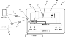
- the security relay includes a control unit that receives a signal from the outside and analyzes the received signal, and determines whether or not to energize the external circuit based on the analysis result, and a power supply unit that supplies power to the control unit
- the control unit includes a receiving unit for receiving a signal from an external device, and the receiving unit receives and analyzes a power permission signal from the external device to determine whether or not to energize the external circuit, and then performs the power supply process.
- the security relay is a contact relay that includes an electromagnetic section having an electromagnet and a contact section that brings a movable contact into contact with or separates a fixed contact as current flows through the electromagnet.
- the control section performs a current flow process that energizes the external circuit and energizes the electromagnetic section by receiving and analyzing a current permission signal from the external device using the receiving section.
- the power supply section is configured to be connected to both the relay terminal on the electromagnetic section side and the relay terminal on the contact section.
- the external circuit 20 is a circuit that controls the flow of electricity using a fuse or a switch. That is, the security relay 1 according to the present invention is configured to control whether electricity flows between the terminals of a fuse or through a switch.
- the security relay 1 according to the present invention is configured to control whether electricity flows between the terminals of a fuse or through a switch.
Landscapes
- Engineering & Computer Science (AREA)
- Power Engineering (AREA)
- Relay Circuits (AREA)
- Remote Monitoring And Control Of Power-Distribution Networks (AREA)
Priority Applications (4)
| Application Number | Priority Date | Filing Date | Title |
|---|---|---|---|
| JP2024513849A JP7555522B1 (ja) | 2023-12-25 | 2023-12-25 | セキュリティリレー |
| PCT/JP2023/046369 WO2025141634A1 (ja) | 2023-12-25 | 2023-12-25 | セキュリティリレー |
| EP23959054.0A EP4611017A4 (en) | 2023-12-25 | 2023-12-25 | SAFETY RELAY |
| CN202380089809.3A CN120548584A (zh) | 2023-12-25 | 2023-12-25 | 安全继电器 |
Applications Claiming Priority (1)
| Application Number | Priority Date | Filing Date | Title |
|---|---|---|---|
| PCT/JP2023/046369 WO2025141634A1 (ja) | 2023-12-25 | 2023-12-25 | セキュリティリレー |
Publications (1)
| Publication Number | Publication Date |
|---|---|
| WO2025141634A1 true WO2025141634A1 (ja) | 2025-07-03 |
Family
ID=92839388
Family Applications (1)
| Application Number | Title | Priority Date | Filing Date |
|---|---|---|---|
| PCT/JP2023/046369 Pending WO2025141634A1 (ja) | 2023-12-25 | 2023-12-25 | セキュリティリレー |
Country Status (4)
| Country | Link |
|---|---|
| EP (1) | EP4611017A4 (https=) |
| JP (1) | JP7555522B1 (https=) |
| CN (1) | CN120548584A (https=) |
| WO (1) | WO2025141634A1 (https=) |
Citations (2)
| Publication number | Priority date | Publication date | Assignee | Title |
|---|---|---|---|---|
| JPH08168162A (ja) | 1994-12-08 | 1996-06-25 | Fuji Electric Co Ltd | 多機能保護リレー |
| US20160358722A1 (en) * | 2015-02-05 | 2016-12-08 | Ramasamy Lakshmanan | Intelligent wireless and wired control of devices |
Family Cites Families (2)
| Publication number | Priority date | Publication date | Assignee | Title |
|---|---|---|---|---|
| US4188547A (en) * | 1976-06-21 | 1980-02-12 | Westinghouse Electric Corp. | Multi-mode control logic circuit for solid state relays |
| JP7300564B1 (ja) * | 2022-02-24 | 2023-06-29 | 株式会社システムデザイン | 電磁継電器 |
-
2023
- 2023-12-25 WO PCT/JP2023/046369 patent/WO2025141634A1/ja active Pending
- 2023-12-25 EP EP23959054.0A patent/EP4611017A4/en active Pending
- 2023-12-25 JP JP2024513849A patent/JP7555522B1/ja active Active
- 2023-12-25 CN CN202380089809.3A patent/CN120548584A/zh active Pending
Patent Citations (2)
| Publication number | Priority date | Publication date | Assignee | Title |
|---|---|---|---|---|
| JPH08168162A (ja) | 1994-12-08 | 1996-06-25 | Fuji Electric Co Ltd | 多機能保護リレー |
| US20160358722A1 (en) * | 2015-02-05 | 2016-12-08 | Ramasamy Lakshmanan | Intelligent wireless and wired control of devices |
Non-Patent Citations (1)
| Title |
|---|
| See also references of EP4611017A4 |
Also Published As
| Publication number | Publication date |
|---|---|
| EP4611017A1 (en) | 2025-09-03 |
| JP7555522B1 (ja) | 2024-09-24 |
| JPWO2025141634A1 (https=) | 2025-07-03 |
| EP4611017A4 (en) | 2026-03-04 |
| CN120548584A (zh) | 2025-08-26 |
Similar Documents
| Publication | Publication Date | Title |
|---|---|---|
| US10460895B2 (en) | Safety switching device for fail-safely disconnecting an electrical load | |
| JP7300564B1 (ja) | 電磁継電器 | |
| JP7049819B2 (ja) | 電気駆動される設備をフェールセーフに停止させる安全回路構成 | |
| CN116859827B (zh) | 一种焊机安全动火的数字授权控制方法及其蓝牙控制模块 | |
| JP7555522B1 (ja) | セキュリティリレー | |
| KR102506922B1 (ko) | 브레이크 모터 감시 장치 | |
| CN104396138A (zh) | 电动机启动器系统及用于使电动机启动器系统工作的方法 | |
| JP5268039B2 (ja) | 回路遮断器 | |
| WO2025027680A1 (ja) | セキュリティリレー | |
| JP7731009B1 (ja) | セキュリティスイッチ | |
| KR20180123334A (ko) | 전류감시보드 | |
| KR101122825B1 (ko) | 누전차단기의 결선오류 방지장치 | |
| KR100685461B1 (ko) | 마이크로프로세서를 이용한 전동기 기동 제어장치 | |
| KR100370104B1 (ko) | 배전 자동화 시스템 | |
| KR200284332Y1 (ko) | 다기능 스위치를 구비한 보조 릴레이 | |
| JP7345986B2 (ja) | リモート入出力装置及び管理システム | |
| CN110058153B (zh) | 继电器监视装置 | |
| CN202917948U (zh) | 电接线保护装置 | |
| KR200272885Y1 (ko) | 전력삽입기의 고장 방지장치 | |
| JP2014157750A (ja) | 回路遮断器 | |
| KR200367006Y1 (ko) | 마이크로프로세서를 이용한 전동기 기동 제어장치 | |
| JPH0597040U (ja) | 電磁石用駆動コイルモニタ回路 | |
| HK1242047A1 (en) | Safety switching device for fail-safe disconnecting of an electrical load | |
| HK1242047B (en) | Safety switching device for fail-safe disconnecting of an electrical load | |
| JPH02204928A (ja) | 光通信機能付電磁開閉器 |
Legal Events
| Date | Code | Title | Description |
|---|---|---|---|
| ENP | Entry into the national phase |
Ref document number: 2024513849 Country of ref document: JP Kind code of ref document: A |
|
| WWE | Wipo information: entry into national phase |
Ref document number: 2024513849 Country of ref document: JP |
|
| WWE | Wipo information: entry into national phase |
Ref document number: 202537043577 Country of ref document: IN |
|
| ENP | Entry into the national phase |
Ref document number: 2023959054 Country of ref document: EP Effective date: 20250527 |
|
| WWE | Wipo information: entry into national phase |
Ref document number: 202380089809.3 Country of ref document: CN |
|
| WWP | Wipo information: published in national office |
Ref document number: 202537043577 Country of ref document: IN |
|
| WWP | Wipo information: published in national office |
Ref document number: 202380089809.3 Country of ref document: CN |
|
| WWP | Wipo information: published in national office |
Ref document number: 2023959054 Country of ref document: EP |