WO2025134497A1 - 遠心圧縮機 - Google Patents
遠心圧縮機 Download PDFInfo
- Publication number
- WO2025134497A1 WO2025134497A1 PCT/JP2024/036498 JP2024036498W WO2025134497A1 WO 2025134497 A1 WO2025134497 A1 WO 2025134497A1 JP 2024036498 W JP2024036498 W JP 2024036498W WO 2025134497 A1 WO2025134497 A1 WO 2025134497A1
- Authority
- WO
- WIPO (PCT)
- Prior art keywords
- axial direction
- casing
- scroll
- radial direction
- discharge
- Prior art date
- Legal status (The legal status is an assumption and is not a legal conclusion. Google has not performed a legal analysis and makes no representation as to the accuracy of the status listed.)
- Pending
Links
Images



Classifications
-
- F—MECHANICAL ENGINEERING; LIGHTING; HEATING; WEAPONS; BLASTING
- F04—POSITIVE - DISPLACEMENT MACHINES FOR LIQUIDS; PUMPS FOR LIQUIDS OR ELASTIC FLUIDS
- F04D—NON-POSITIVE-DISPLACEMENT PUMPS
- F04D29/00—Details, component parts, or accessories
- F04D29/40—Casings; Connections of working fluid
- F04D29/42—Casings; Connections of working fluid for radial or helico-centrifugal pumps
-
- F—MECHANICAL ENGINEERING; LIGHTING; HEATING; WEAPONS; BLASTING
- F04—POSITIVE - DISPLACEMENT MACHINES FOR LIQUIDS; PUMPS FOR LIQUIDS OR ELASTIC FLUIDS
- F04D—NON-POSITIVE-DISPLACEMENT PUMPS
- F04D29/00—Details, component parts, or accessories
- F04D29/40—Casings; Connections of working fluid
- F04D29/42—Casings; Connections of working fluid for radial or helico-centrifugal pumps
- F04D29/44—Fluid-guiding means, e.g. diffusers
Definitions
- the present disclosure relates to centrifugal compressors.
- This application claims priority to Japanese Patent Application No. 2023-213861, filed in Japan on December 19, 2023, the contents of which are incorporated herein by reference.
- a multi-stage centrifugal compressor which has multiple stages of impellers that compress gas, is known as a type of centrifugal rotating machine.
- gas is drawn into a casing from an intake port, compressed sequentially by multiple stages of impellers, and discharged outside the casing from a discharge port.
- a discharge scroll is connected to the discharge port, which keeps the flow rate of the gas discharged from the impeller through the diffuser flow passage constant and reduces the pressure.
- Patent Document 1 describes a discharge volute (discharge scroll) that is formed so that the radial spacing gradually increases toward the downstream side of the circumferential direction of gas flow.
- This discharge volute is formed by fixing volute pieces, whose radial wall thickness gradually decreases toward the downstream side of the circumferential direction of gas flow, to the casing.
- a discharge scroll when forming a discharge scroll, it is formed in a shape that allows the working fluid, such as gas, discharged from the diffuser passage radially outward to flow inward in the radial direction after changing its flow direction in the radial direction, or a shape that allows the working fluid to flow in without changing its flow direction.
- a discharge scroll that allows the working fluid to flow in after changing its flow direction separation is likely to occur when the working fluid flows into the discharge scroll.
- the discharge scroll in a discharge scroll that allows the working fluid to flow in without changing its flow direction, the discharge scroll is formed radially outward from the diffuser passage, and the outer diameter becomes too large for a centrifugal compressor.
- This disclosure provides a centrifugal compressor that can form a compact discharge scroll while suppressing flow separation when the working fluid flows in.
- the centrifugal compressor comprises a rotating shaft extending in an axial direction along which a central axis extends, and a casing having an inlet formed on a first side in the axial direction and an outlet formed on a second side in the axial direction, the rotating shaft being disposed within the casing and having an impeller that compresses and discharges a working fluid supplied from the first side in the axial direction to the outside in a radial direction based on the central axis, the casing comprising a diaphragm formed in a cylindrical shape extending in the axial direction so as to cover the impeller, an outer casing formed in a cylindrical shape extending in the axial direction so as to cover the diaphragm, and a casing having a cylindrical shape extending in the axial direction so as to cover the outer casing.
- the casing has a head that closes the openings at both ends in the axial direction, a diffuser passage that guides the working fluid discharged from the impeller toward the outside in the radial direction, and a discharge scroll that guides the working fluid discharged from the impeller to the discharge port.
- the discharge scroll is connected to the diffuser passage on the outside in the radial direction and extends in the circumferential direction around the central axis.
- the discharge scroll is formed so that the radial spacing is constant when viewed from the axial direction, and the axial spacing gradually narrows as it moves away from the discharge port in the circumferential direction.
- the centrifugal compressor disclosed herein can form a compact discharge scroll while suppressing flow separation when the working fluid flows in.
- FIG. 1 is a cross-sectional view of a centrifugal compressor according to an embodiment of the present disclosure.
- FIG. 2 is an enlarged cross-sectional view showing a configuration around a discharge scroll of the centrifugal compressor.
- 3 is a cross-sectional view taken along line III-III in FIG. 1 , showing the discharge scroll of the centrifugal compressor as viewed from the axial direction.
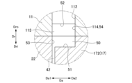
- 4 is an enlarged view of a main part taken along line IV-IV in FIG. 3, showing a change in the axial width of the discharge scroll of the centrifugal compressor.
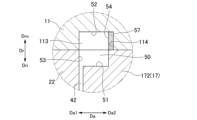
- 4 is an enlarged view of a main part taken along line VV in FIG. 3, showing a change in the axial width of the discharge scroll of the centrifugal compressor.
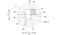
- FIG. 6 is an enlarged view of a main part taken along line VI-VI in FIG. 3, showing a change in the axial width of the discharge scroll of the centrifugal compressor.
- FIG. 7 is an enlarged view of a main part taken along line VII-VII in FIG. 3, showing a change in the axial width of the discharge scroll of the centrifugal compressor.
- the centrifugal compressor 1 in this embodiment is a single-shaft multi-stage centrifugal compressor.
- the centrifugal compressor 1 mainly includes a rotating shaft 2 that rotates around a central axis O, and a casing 10 formed to surround the rotating shaft 2.
- the rotating shaft 2 extends in an axial direction Da.
- the rotating shaft 2 extends so as to penetrate the inside of the casing 10 along a central axis O.
- the rotating shaft 2 has a rotating shaft main body 21 and an impeller 22.
- the direction in which the central axis O extends is defined as the axial direction Da.
- the axial direction Da of the rotating shaft 2 is along a horizontal plane.
- the central axis O extends horizontally.
- the radial direction based on the central axis O is simply defined as the radial direction Dr.
- the direction around the rotating shaft 2 centered on the central axis O is defined as the circumferential direction Dc.
- the rotating shaft body 21 is formed in a cylindrical shape extending in the axial direction Da.
- the end of the rotating shaft body 21 on the first side Da1 in the axial direction Da is supported by the casing 10 by a journal bearing 32A and a thrust bearing 31 so as to be rotatable about the central axis O.
- the end of the rotating shaft body 21 on the second side Da2 in the axial direction Da is supported by the casing 10 by a journal bearing 32B so as to be rotatable about the central axis O.
- the impeller 22 is disposed on the outer side Dro of the rotating shaft body 21 in the radial direction Dr based on the central axis O. Multiple impellers 22 are disposed apart in the axial direction Da within the casing 10. In this embodiment, for example, six impellers 22 are disposed at intervals in the axial direction Da.
- Each impeller 22 compresses and discharges the working fluid (e.g., gas) supplied from the first side Da1 in the axial direction Da to the outside Dro in the radial direction Dr.
- An impeller flow path 23 is formed inside each impeller 22.
- the cross-sectional area of the impeller flow path 23 gradually decreases from the inside Dri in the radial direction Dr to the outside Dro in the radial direction Dr. As a result, the working fluid flowing through the impeller flow path 23 while the impeller 22 is rotating is gradually compressed to a high pressure.
- Each impeller 22 may be a closed impeller having a cover, or an open impeller without a cover.
- the casing 10 is formed to surround the rotating shaft main body 21 and the multiple impellers 22 from the outside Dro in the radial direction Dr.
- the casing 10 includes an outer casing 11, a suction port 111, a discharge port 112, multiple diaphragms 15, and a head 17.
- the external casing 11 is formed in a cylindrical shape extending in the axial direction Da.
- the external casing 11 is formed to cover the rotating shaft 2, the multiple diaphragms 15, and the head 17 from the outside Dro in the radial direction Dr.
- the external casing 11 forms a suction port 111 and a discharge port 112.
- the suction port 111 is formed on the first side Da1 in the axial direction Da of the external casing 11.
- the suction port 111 allows the working fluid to flow into the external casing 11 from the outside.
- the discharge port 112 is formed on the second side Da2 in the axial direction Da of the external casing 11.
- the discharge port 112 discharges the working fluid compressed through all the impellers 22 inside the external casing 11 to the outside of the external casing 11.
- the discharge port 112 is positioned away from the suction port 111 on the second side Da2 in the axial direction Da.
- the multiple diaphragms 15 are arranged on the inner side Dri of the outer casing 11 in the radial direction Dr.
- the multiple diaphragms 15 are formed in a cylindrical shape extending in the axial direction Da as a whole so as to cover the impellers 22 of each stage.
- Each diaphragm 15 is formed in a disk shape centered on the central axis O.
- the multiple diaphragms 15 are stacked in the axial direction Da, and adjacent diaphragms 15 are fixed to each other by welding or bolts.
- the multiple diaphragms 15 are fixed to each other to cover the circumference of the rotating shaft 2 and form a casing flow passage 40 inside that connects the multiple impellers 22.
- the multiple diaphragms 15 also form a bundle together with the rotating shaft 2, the head 17, the journal bearings 32A and 32B, and the thrust bearing 31.
- the bundle is housed in the outer casing 11.
- the multiple diaphragms 15, the rotating shaft 2, the head 17, the journal bearings 32A and 32B, and the thrust bearing 31 are all movable together as a single unit.
- the multiple diaphragms 15 also have a casing flow path 40 that includes an inlet flow path 41, a diffuser flow path 42, and a return flow path 43.
- the inlet flow passage 41 guides the working fluid from the outer side Dro in the radial direction Dr to the inner side Dri in the radial direction Dr.
- the inlet flow passage 41 changes the working fluid heading toward the inner side Dri in the radial direction Dr to a flow toward the second side Da2 in the axial direction Da, and guides it to the impeller 22.
- the inlet flow passage 41 changes the flow direction of the working fluid to the second side Da2 in the axial direction Da, and guides it to the impeller flow passage 23 of the impeller 22.
- the diffuser passage 42 extends from the inner side Dri in the radial direction Dr to the outer side Dro.
- the end of the diffuser passage 42 on the inner side Dri in the radial direction Dr is connected to the end of the impeller passage 23 on the outer side Dro in the radial direction Dr.
- the diffuser passage 42 guides the working fluid compressed by the impeller 22 from the inner side Dri in the radial direction Dr to the outer side Dro in the radial direction Dr.
- the return flow passage 43 reverses the flow direction of the working fluid that has passed through the diffuser flow passage 42 and flowed from the inner side Dri in the radial direction Dr to the outer side Dro in the radial direction Dr.
- the return flow passage 43 guides the working fluid flowing toward the outer side Dro in the radial direction Dr to the inner side Dri in the radial direction Dr.
- One end of the return flow passage 43 (first side Da1 in the axial direction Da), which is upstream in the flow direction of the working fluid, is connected to the diffuser flow passage 42.
- the other end side of the return flow passage 43 (second side Da2 in the axial direction Da), which is downstream in the flow direction of the working fluid, is connected to the next introduction flow passage 41.
- the heads 17 are arranged in pairs to cover the openings at both ends of the cylindrical outer casing 11 in the axial direction Da. They are annular members centered on the central axis O. The pair of heads 17 are arranged inside the outer casing 11. In this embodiment, the heads 17 have a first casing head 171 and a second casing head 172.
- the first casing head 171 is positioned so as to close the opening on the first side Da1 in the axial direction Da of the outer casing 11. In other words, the first casing head 171 is positioned adjacent to the first side Da1 in the axial direction Da relative to the multiple diaphragms 15.
- An intake scroll that takes in external working fluid into the casing flow path 40 via the intake port 111 is formed between the first casing head 171 and the first-stage diaphragm 15 of the multiple diaphragms 15 that is positioned furthest to the first side Da1 in the axial direction Da.
- the first casing head 171 is fixed to the integrated multiple diaphragms 15 by bolts or the like. As a result, the first casing head 171 is integrated with the diaphragm 15.
- the second casing head 172 is positioned so as to close the opening on the second side Da2 in the axial direction Da of the outer casing 11.
- the second casing head 172 is positioned adjacent to the second side Da2 in the axial direction Da relative to the multiple diaphragms 15. Therefore, the second casing head 172 is adjacent to the final stage diaphragm 15, which is positioned furthest on the second side Da2 in the axial direction Da, among the multiple diaphragms 15.
- the second casing head 172 is fixed to the integrated multiple diaphragms 15 by bolts or the like. As a result, the second casing head 172 is integrated with the diaphragms 15.
- the casing 10 of the centrifugal compressor 1 has a discharge scroll 50 and a flow passage forming portion 57.
- the discharge scroll 50 guides the working fluid discharged from the final stage impeller 22 among the multiple impellers 22 to the discharge port 112.
- the discharge scroll 50 is connected to the diffuser flow passage 42 at the outer side Dro in the radial direction Dr.
- the discharge scroll 50 extends in the circumferential direction Dc around the central axis O.
- the discharge scroll 50 is a flow passage formed in a spiral shape over one revolution in the circumferential direction Dc around the central axis O.
- the discharge scroll 50 is connected to the diffuser flow passage 42 at the inner side Dri in the radial direction Dr over the entire circumference.
- the discharge scroll 50 is connected to the discharge port 112 at the outer side Dro in the radial direction Dr in a part of the circumferential direction Dc.
- the discharge scroll 50 is formed with a constant interval in the radial direction Dr when viewed from the axial direction Da.
- the discharge scroll 50 is formed such that the spacing in the axial direction Da gradually narrows as it moves away from the discharge port 112 in the circumferential direction Dc. That is, as shown in Figure 4, the discharge scroll 50 is formed such that the spacing in the axial direction Da is widest at a position closest to the discharge port 112 in the circumferential direction Dc.
- the spacing in the axial direction Da of the discharge scroll 50 gradually narrows as it moves away from the discharge port 112 in the circumferential direction Dc.
- the spacing in the axial direction Da gradually narrows so that the flow speed of the working fluid flowing inside is constant in the circumferential direction Dc.
- the discharge scroll 50 is formed by a space formed in the second casing head 172 and the outer casing 11.
- the discharge scroll 50 is surrounded by a scroll inner circumferential surface 51 on the inner side Dri in the radial direction Dr, a scroll outer circumferential surface 52 on the outer side Dro in the radial direction Dr, a first flow passage forming surface 53 arranged on the second side Da2 in the axial direction Da, and a second flow passage forming surface (flow passage forming surface) 54 arranged on the second side Da2 in the axial direction Da.
- the scroll inner circumferential surface 51 is located at the innermost Dri in the radial direction Dr in the discharge scroll 50.
- the scroll inner circumferential surface 51 is a surface facing the outer side Dro in the radial direction Dr.
- the scroll inner circumferential surface 51 is formed by the second casing head 172.
- the scroll inner circumferential surface 51 is located on the outer side Dro in the radial direction Dr relative to the diffuser flow passage 42.
- the scroll inner circumferential surface 51 is located on the inner side Dri in the radial direction Dr relative to the boundary between the second casing head 172 and the diaphragm 15 and the outer casing 11.
- the scroll outer peripheral surface 52 is located at the outermost Dro in the radial direction Dr in the discharge scroll 50.
- the scroll outer peripheral surface 52 faces the inner peripheral surface Dri in the radial direction Dr.
- the scroll outer peripheral surface 52 faces the scroll inner peripheral surface 51 in the radial direction Dr.
- the distance between the scroll outer peripheral surface 52 and the scroll inner peripheral surface 51 in the radial direction Dr is constant in both the axial direction Da and the circumferential direction Dc.
- the scroll outer peripheral surface 52 is formed by the external casing 11.
- the scroll outer peripheral surface 52 is located on the inner side Dri in the radial direction Dr relative to the outer peripheral surface of the external casing 11 in the radial direction Dr.
- the scroll inner peripheral surface 51 is located on the outer side Dro in the radial direction Dr relative to the boundary between the second casing head 172 and the diaphragm 15 and the external casing 11 when viewed from the circumferential direction Dc.
- the first flow passage forming surface 53 is located at the most first side Da1 in the axial direction Da of the discharge scroll 50.
- the first flow passage forming surface 53 faces the second side Da2 in the axial direction Da.
- the first flow passage forming surface 53 is formed by the outer casing 11 and the diaphragm 15.
- the first flow passage forming surface 53 is formed in a flat shape so as to be integrally connected at the same position in the axial direction Da as the surface that forms the diffuser flow passage 42.
- the second flow passage forming surface 54 is located at the most second side Da2 in the axial direction Da in the discharge scroll 50.
- the second flow passage forming surface 54 faces the first flow passage forming surface 53 in the axial direction Da.
- the distance between the first flow passage forming surface 53 and the second flow passage forming surface 54 in the axial direction Da gradually increases in the circumferential direction Dc as the discharge port 112 approaches.
- the second flow passage forming surface 54 is a surface facing the first side Da1 in the axial direction Da.
- the second flow passage forming surface 54 is formed by the second casing head 172 and a flow passage forming section 57 described later.
- the second flow passage forming surface 54 extends from the scroll inner peripheral surface 51 to the outside Dro in the radial direction Dr.
- the flow passage forming portion 57 forms at least a part of the second flow passage forming surface 54.
- the flow passage forming portion 57 forms a part of the second flow passage forming surface 54 at a position where it overlaps with the external casing 11 in the radial direction Dr.
- the flow passage forming portion 57 forms an area on the outer side Dro of the second flow passage forming surface 54 in the radial direction Dr instead of the external casing 11.
- the area on the inner side Dri of the second flow passage forming surface 54 in the radial direction Dr is formed by the second casing head 172.
- the flow passage forming portion 57 is fixed to the external casing 11 at the outer side Dro of the radial direction Dr relative to the second casing head 172.
- the flow passage forming portion 57 is arranged in a recess 113 formed in the external casing 11.
- the recess 113 is recessed from the inner peripheral surface of the external casing 11 to the outer side Dro of the radial direction Dr.
- the recess 113 also forms a space that forms the discharge scroll 50 in the external casing 11.
- the recess 113 is formed with a constant width in the axial direction Da.
- the flow path forming portion 57 is a surface that forms the recess 113, and is disposed in contact with a space forming surface 114 that faces the first side Da1 in the axial direction Da in the outer casing 11. As shown in Figures 4 to 7, the flow path forming portion 57 is formed so that the spacing in the axial direction Da gradually increases as it moves away from the discharge port 112 in the circumferential direction Dc.
- the flow path forming portion 57 is not positioned at the position closest to the discharge port 112 in the circumferential direction Dc. In other words, the flow path forming portion 57 is formed with the narrowest spacing in the axial direction Da at the position closest to the discharge port 112 in the circumferential direction Dc. Then, as shown in FIGS. 5 to 7, the flow path forming portion 57 has a gradually thicker spacing in the axial direction Da as it moves away from the discharge port 112 in the circumferential direction Dc. In this way, the flow path forming portion 57 forms the second flow path forming surface 54 together with the surface of the second casing head 172 facing the second side Da2 in the axial direction Da.
- the working fluid discharged from the impeller 22 of the final stage passes through the diffuser passage 42 of the final stage and flows into the discharge scroll 50.
- the discharge scroll 50 is connected to the diffuser passage 42 of the final stage at the outer side Dro of the radial direction Dr. Therefore, when the working fluid flows from the diffuser passage 42 into the discharge scroll 50, the flow direction is not changed. As a result, separation of the working fluid when flowing from the diffuser passage 42 into the discharge scroll 50 can be suppressed.
- the discharge scroll 50 has a constant interval in the radial direction Dr when viewed from the axial direction Da.
- the discharge scroll 50 has a constant interval in the radial direction Dr at any position in the circumferential direction Dc. Furthermore, the discharge scroll 50 is formed so that the interval in the axial direction Da gradually narrows as it moves away from the discharge port 112 in the circumferential direction Dc. Therefore, in the discharge scroll 50, by changing the spacing in the axial direction Da, a flow path area for the working fluid to flow from the diffuser flow path 42 to the discharge port 112 can be secured. As a result, the required performance can be secured for the discharge scroll 50 while suppressing expansion of the discharge scroll 50 in the radial direction Dr. In this way, the discharge scroll 50 can be formed compactly while suppressing flow separation when the working fluid flows in.
- the scroll inner circumferential surface 51 is disposed on the outer side Dro of the diffuser passage 42 in the radial direction Dr. Therefore, when the working fluid flows from the diffuser passage 42 into the discharge scroll 50, there is no need to change the flow direction of the working fluid from the outer side Dro to the inner side Dri of the radial direction Dr. Therefore, flow separation when the working fluid flows into the discharge scroll 50 can be suppressed with high precision.
- the spacing of the discharge scroll 50 in the axial direction Da gradually narrows so that the flow speed of the working fluid flowing inside in the circumferential direction Dc is constant. This makes it possible to reduce stall and pressure loss of the working fluid flowing through the discharge scroll 50 while suppressing expansion of the discharge scroll 50 in the radial direction Dr. In this way, stable performance can be ensured even with a compact discharge scroll 50.
- the discharge scroll 50 has an inner scroll surface 51 formed by the second casing head 172 and an outer scroll surface 52 formed by the external casing 11. Therefore, the space on the inner side Dri in the radial direction Dr of the discharge scroll 50 is formed in the second casing head 172. On the other hand, the space on the outer side Dro in the radial direction Dr of the discharge scroll 50 is formed in the external casing 11. In this way, by forming a part of the discharge scroll 50 in the external casing 11, the size of the radial direction Dr of the second casing head 172 can be reduced. As a result, the size of the radial direction Dr of the external casing 11 that covers the second casing head 172 can also be reduced. This makes it possible to form a discharge scroll 50 that can ensure stable performance while reducing the size of the radial direction Dr of the centrifugal compressor 1.
- a part of the second flow passage forming surface 54 is formed by a flow passage forming portion 57.
- the flow passage forming portion 57 is formed so that the spacing in the axial direction Da gradually increases as it moves away from the discharge port 112 in the circumferential direction Dc.
- the flow passage forming part 57 is fixed in the recess 113 of the external casing 11 at the outer side Dro in the radial direction Dr relative to the second casing head 172. Therefore, the flow passage forming part 57 forms the area of the outer side Dro in the radial direction Dr of the second flow passage forming surface 54 at a position where it overlaps with the external casing 11, instead of the external casing 11.
- the external casing 11 is not only larger in the radial direction Dr than the diaphragm 15 and the second casing head 172, but is also a huge and heavy member that is very long in the axial direction Da.
- the area of the inner side Dri in the radial direction Dr of the second flow passage forming surface 54 is formed by the second casing head 172.
- the flow passage forming portion 57 is not arranged in the second casing head 172, and a part of the discharge scroll 50 is formed so as to be recessed from the outer peripheral surface of the second casing head 172.
- the second casing head 172 a smaller member than the outer casing 11, but the machined part is the outer peripheral surface rather than the inner peripheral surface. Therefore, even a three-dimensional recess in which the spacing in the axial direction Da changes in the circumferential direction Dc can be formed relatively easily. Therefore, the size of the flow passage forming portion 57 can be reduced, and the discharge scroll 50 can be produced at reduced cost.
- the centrifugal compressor 1 is not limited to a structure in which the discharge scroll 50 is formed via the flow passage forming portion 57. In other words, the centrifugal compressor 1 does not have to have the flow passage forming portion 57. In that case, the second flow passage forming surface 54 may be formed by the outer casing 11 and the second casing head 172.
- the flow path forming part 57 is not limited to a structure in which it is fixed to the external casing 11 and forms an area on the outer side Dro of the second flow path forming surface 54 in the radial direction Dr in place of the external casing 11.
- the flow path forming part 57 may be fixed to the second casing head 172.
- the flow path forming part 57 may form an area on the inner side Dri of the second flow path forming surface 54 in the radial direction Dr in place of the second casing head 172.
- the flow path forming part 57 may be fixed to both the external casing 11 and the second casing head 172. In that case, the flow path forming part 57 may form the entire area of the second flow path forming surface 54 in place of the external casing 11 and the second casing head 172.
- the flow path forming portion 57 may have any structure as long as it can form at least a part of the second flow path forming surface 54.
- the flow path forming portion 57 may be formed as a block-shaped solid structure, or may be formed as a structure with a hollow interior.
- the flow path forming portion 57 may have a structure including, for example, a plate material that forms a part of the second flow path forming surface 54, and a support member that supports this plate material on the space forming surface 114.
- the discharge scroll 50 is not limited to a structure formed as a space spanning the outer casing 11 and the second casing head 172.
- the discharge scroll 50 may be formed only in the outer casing 11, or only in the second casing head 172.
- the centrifugal compressor 1 according to the embodiment can be understood as follows, for example.
- the centrifugal compressor 1 according to the first aspect comprises a rotating shaft 2 extending in an axial direction Da along which a central axis O extends, and a casing 10 having an intake port 111 formed on a first side Da1 in the axial direction Da and an exhaust port 112 formed on a second side Da2 in the axial direction Da.
- the rotating shaft 2 is disposed within the casing 10 and has an impeller 22 that compresses and exhausts a working fluid supplied from the first side Da1 in the axial direction Da to the outside Dro in a radial direction Dr based on the central axis O.
- the casing 10 includes a diaphragm 15 formed in a cylindrical shape extending in the axial direction Da so as to cover the impeller 22, and an external casing 10 formed in a cylindrical shape extending in the axial direction Da so as to cover the diaphragm 15.
- the outer casing 11 has a head 17 that closes the openings at both ends of the axial direction Da of the outer casing 11, a diffuser passage 42 that guides the working fluid discharged from the impeller 22 toward the outer side Dro of the radial direction Dr, and a discharge scroll 50 that guides the working fluid discharged from the impeller 22 to the discharge port 112.
- the discharge scroll 50 is connected to the diffuser passage 42 at the outer side Dro of the radial direction Dr, extends in the circumferential direction Dc around the central axis O, and is formed so that the interval in the radial direction Dr when viewed from the axial direction Da is constant, and the interval in the axial direction Da gradually narrows as it moves away from the discharge port 112 in the circumferential direction Dc.
- the discharge scroll 50 has a constant radial distance Dr when viewed from the axial direction Da.
- the discharge scroll 50 has a constant radial distance Dr regardless of the position in the circumferential direction Dc.
- the discharge scroll 50 is formed so that the distance in the axial direction Da gradually narrows as it moves away from the discharge port 112 in the circumferential direction Dc.
- the flow path area through which the working fluid flows from the diffuser passage 42 to the discharge port 112 can be secured by changing the distance in the axial direction Da.
- the required performance can be secured for the discharge scroll 50 while suppressing the expansion of the discharge scroll 50 in the radial direction Dr.
- the discharge scroll 50 can be made compact while suppressing flow separation when the working fluid flows in.
- the centrifugal compressor 1 according to the second aspect is the centrifugal compressor 1 according to (1), in which the spacing of the discharge scroll 50 in the axial direction Da gradually narrows so that the flow velocity of the working fluid flowing inside the discharge scroll 50 in the circumferential direction Dc is constant.
- This configuration makes it possible to reduce stall and pressure loss of the working fluid flowing through the discharge scroll 50 while suppressing expansion of the discharge scroll 50 in the radial direction Dr. In this way, stable performance can be ensured even with a compact discharge scroll 50.
- the centrifugal compressor 1 according to the third aspect is the centrifugal compressor 1 according to (1) or (2), in which the discharge scroll 50 has a scroll inner circumferential surface 51 on the inner side Dri in the radial direction Dr formed by the head 17, and a scroll outer circumferential surface 52 on the outer side Dro in the radial direction Dr that faces the scroll inner circumferential surface 51 in the radial direction Dr formed by the outer casing 11.
- the space on the inner side Dri in the radial direction Dr of the discharge scroll 50 is formed in the head 17.
- the space on the outer side Dro in the radial direction Dr of the discharge scroll 50 is formed in the external casing 11.
- the size of the radial direction Dr of the head 17 can be reduced.
- the size of the radial direction Dr of the external casing 11 that covers the head 17 can also be reduced. This makes it possible to form a discharge scroll 50 that can ensure stable performance while reducing the size of the radial direction Dr of the centrifugal compressor 1.
- the centrifugal compressor 1 according to the fourth aspect is a centrifugal compressor 1 according to any one of (1) to (3), in which the casing 10 has a flow passage forming portion 57 arranged on the second side Da2 of the axial direction Da in the discharge scroll 50 and forming at least a part of a flow passage forming surface facing the first side Da1 of the axial direction Da, and the flow passage forming portion 57 is formed so that the spacing in the axial direction Da gradually increases as it moves away from the discharge port 112 in the circumferential direction Dc.
- the centrifugal compressor 1 according to the fifth aspect is the centrifugal compressor 1 according to (4), in which the flow passage forming portion 57 is fixed to the external casing 11 on the outer side Dro of the radial direction Dr relative to the head 17, and forms a part of the flow passage forming surface at a position overlapping with the external casing 11 in the radial direction Dr.
- the flow passage forming portion 57 forms the area of the outer side Dro in the radial direction Dr of the second flow passage forming surface 54 at a position where it overlaps with the external casing 11, instead of the external casing 11.
- the external casing 11 is not only larger in the radial direction Dr than the diaphragm 15 and the head 17, but is also a huge and heavy member that is very long in the axial direction Da. It is very difficult to machine a three-dimensional recess 113 on the inner surface of such an external casing 11, in which the spacing in the axial direction Da changes in the circumferential direction Dc.
- the width of the recess 113 itself in the external casing 11 in the axial direction Da can be made constant. This makes it easier to machine the external casing 11, and makes it easier to create the discharge scroll 50.
- the centrifugal compressor disclosed herein can form a compact discharge scroll while suppressing flow separation when the working fluid flows in.
Landscapes
- Engineering & Computer Science (AREA)
- Mechanical Engineering (AREA)
- General Engineering & Computer Science (AREA)
- Structures Of Non-Positive Displacement Pumps (AREA)
Applications Claiming Priority (2)
| Application Number | Priority Date | Filing Date | Title |
|---|---|---|---|
| JP2023-213861 | 2023-12-19 | ||
| JP2023213861A JP2025097596A (ja) | 2023-12-19 | 2023-12-19 | 遠心圧縮機 |
Publications (1)
| Publication Number | Publication Date |
|---|---|
| WO2025134497A1 true WO2025134497A1 (ja) | 2025-06-26 |
Family
ID=96136785
Family Applications (1)
| Application Number | Title | Priority Date | Filing Date |
|---|---|---|---|
| PCT/JP2024/036498 Pending WO2025134497A1 (ja) | 2023-12-19 | 2024-10-11 | 遠心圧縮機 |
Country Status (2)
| Country | Link |
|---|---|
| JP (1) | JP2025097596A (https=) |
| WO (1) | WO2025134497A1 (https=) |
Citations (4)
| Publication number | Priority date | Publication date | Assignee | Title |
|---|---|---|---|---|
| JPS5632099A (en) * | 1979-08-24 | 1981-04-01 | Borg Warner | Enlarged scroll diffuser for radial flow impeller |
| JPH08232893A (ja) * | 1995-02-22 | 1996-09-10 | Mitsubishi Heavy Ind Ltd | 遠心圧縮機 |
| WO2020012185A1 (en) * | 2018-07-11 | 2020-01-16 | Dyson Technology Limited | A centrifugal compressor |
| JP2023119272A (ja) * | 2022-02-16 | 2023-08-28 | 三菱重工コンプレッサ株式会社 | 遠心圧縮機 |
-
2023
- 2023-12-19 JP JP2023213861A patent/JP2025097596A/ja active Pending
-
2024
- 2024-10-11 WO PCT/JP2024/036498 patent/WO2025134497A1/ja active Pending
Patent Citations (4)
| Publication number | Priority date | Publication date | Assignee | Title |
|---|---|---|---|---|
| JPS5632099A (en) * | 1979-08-24 | 1981-04-01 | Borg Warner | Enlarged scroll diffuser for radial flow impeller |
| JPH08232893A (ja) * | 1995-02-22 | 1996-09-10 | Mitsubishi Heavy Ind Ltd | 遠心圧縮機 |
| WO2020012185A1 (en) * | 2018-07-11 | 2020-01-16 | Dyson Technology Limited | A centrifugal compressor |
| JP2023119272A (ja) * | 2022-02-16 | 2023-08-28 | 三菱重工コンプレッサ株式会社 | 遠心圧縮機 |
Also Published As
| Publication number | Publication date |
|---|---|
| JP2025097596A (ja) | 2025-07-01 |
Similar Documents
| Publication | Publication Date | Title |
|---|---|---|
| JP4875644B2 (ja) | タービンおよびこれを備えるターボチャージャ | |
| JP5709898B2 (ja) | 回転機械 | |
| CN113446260B (zh) | 叶轮以及离心压缩机 | |
| JP6583933B2 (ja) | 多段遠心圧縮機 | |
| JP5727881B2 (ja) | 輪切形多段ポンプ | |
| WO2018155546A1 (ja) | 遠心圧縮機 | |
| WO2017170083A1 (ja) | 遠心圧縮機 | |
| CN111608952B (zh) | 叶轮以及旋转机械 | |
| WO2025134497A1 (ja) | 遠心圧縮機 | |
| JP7774670B2 (ja) | インペラ、及び遠心圧縮機 | |
| CN115362310A (zh) | 涡轮以及增压器 | |
| JP7763679B2 (ja) | 遠心圧縮機 | |
| JP6963471B2 (ja) | 回転機械 | |
| CN113544369B (zh) | 涡轮机 | |
| JP2011231780A (ja) | タービンおよびこれを備えるターボチャージャ | |
| JP2025117889A (ja) | 遠心圧縮機 | |
| JP7348831B2 (ja) | インペラ及び回転機械 | |
| US12480416B2 (en) | Inlet guide vane and rotary machine | |
| US20250198310A1 (en) | Turbine | |
| JP2020159281A (ja) | 圧縮機 | |
| JP7351784B2 (ja) | 遠心回転機械 | |
| JP7350521B2 (ja) | 回転機械 | |
| JP2020067074A (ja) | 遠心圧縮機及びシールユニット | |
| WO2024053148A1 (ja) | タービン | |
| WO2022259625A1 (ja) | 遠心圧縮機および過給機 |
Legal Events
| Date | Code | Title | Description |
|---|---|---|---|
| 121 | Ep: the epo has been informed by wipo that ep was designated in this application |
Ref document number: 24906885 Country of ref document: EP Kind code of ref document: A1 |