WO2025134350A1 - ヒートプロテクタ構造 - Google Patents
ヒートプロテクタ構造 Download PDFInfo
- Publication number
- WO2025134350A1 WO2025134350A1 PCT/JP2023/046108 JP2023046108W WO2025134350A1 WO 2025134350 A1 WO2025134350 A1 WO 2025134350A1 JP 2023046108 W JP2023046108 W JP 2023046108W WO 2025134350 A1 WO2025134350 A1 WO 2025134350A1
- Authority
- WO
- WIPO (PCT)
- Prior art keywords
- heat protector
- plate
- harness
- purification device
- exhaust purification
- Prior art date
- Legal status (The legal status is an assumption and is not a legal conclusion. Google has not performed a legal analysis and makes no representation as to the accuracy of the status listed.)
- Pending
Links
Images

Classifications
-
- B—PERFORMING OPERATIONS; TRANSPORTING
- B60—VEHICLES IN GENERAL
- B60K—ARRANGEMENT OR MOUNTING OF PROPULSION UNITS OR OF TRANSMISSIONS IN VEHICLES; ARRANGEMENT OR MOUNTING OF PLURAL DIVERSE PRIME-MOVERS IN VEHICLES; AUXILIARY DRIVES FOR VEHICLES; INSTRUMENTATION OR DASHBOARDS FOR VEHICLES; ARRANGEMENTS IN CONNECTION WITH COOLING, AIR INTAKE, GAS EXHAUST OR FUEL SUPPLY OF PROPULSION UNITS IN VEHICLES
- B60K13/00—Arrangement in connection with combustion air intake or gas exhaust of propulsion units
- B60K13/04—Arrangement in connection with combustion air intake or gas exhaust of propulsion units concerning exhaust
Definitions
- This disclosure relates to a heat protector structure for an exhaust purification device.
- Patent Document 1 discloses a heat protector that can be simply fixed to the exhaust pipe.
- Such exhaust pipes are fitted with exhaust purification devices that purify harmful substances contained in the exhaust.
- exhaust purification devices have multiple sensors.
- the sensors are connected to harnesses that transmit the values detected by the sensors to an ECU (Electronic Control Unit). Harnesses extending from such sensors are also required to suppress the heat they receive from the exhaust purification device.
- the objective of this disclosure is to provide a heat protector structure that can suppress the heat absorption of the harness.
- the heat protector structure disclosed herein is a heat protector structure that covers an exhaust purification device, and includes a first heat protector that covers a first region of the surface of the exhaust purification device, and a second heat protector that covers a second region of the surface that is different from the first region, and the second heat protector has a harness fixing portion that fixes a harness connected to a sensor fixed to the exhaust purification device.
- This heat protector structure allows the second heat protector to cover the second area of the surface of the exhaust purification device that cannot be covered by the first heat protector. By fixing the harness extending from the sensor to the second heat protector, it is possible to prevent the harness from receiving heat.
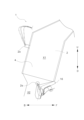
- FIG. 2 is a rear view showing a heat protector structure according to an embodiment of the present disclosure.
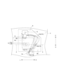
- FIG. 2 is a side view illustrating a heat protector structure according to an embodiment of the present disclosure.
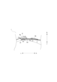
- FIG. 13 is a rear view illustrating a mid-sensor heat protector according to an embodiment of the present disclosure.
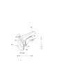
- AA cross-sectional view of FIG. 3. 1 illustrates an outlet sensor heat protector according to an embodiment of the present disclosure.
- the heat protector structure 1 of this embodiment is mounted on a vehicle. Therefore, in the drawings, the front side of the vehicle is marked as F, the rear side as B, the right side as R, the left side as L, the top side as U, and the bottom side as D, with the vehicle as the reference point.
- the heat protector structure 1 covers the surface of an exhaust purification device 2 that purifies the exhaust gas discharged from an engine E.
- the heat protector structure 1 includes a main heat protector (an example of a first heat protector) 4, an intermediate sensor heat protector (an example of a second heat protector) 6, and an outlet sensor heat protector (an example of a second heat protector) 16.
- the exhaust purification device 2 is a device that purifies the exhaust gas discharged from the engine E.
- the exhaust purification device 2 is a diesel particulate filter that purifies the exhaust gas from a diesel engine.
- the exhaust purification device 2 is disposed on the right side of the engine, tilted vertically.
- the exhaust purification device 2 has multiple sensors 2a fixed to it.
- the sensors 2a are temperature sensors that detect the temperature of the exhaust gas passing through the exhaust purification device 2.
- a total of three sensors 2a are arranged, one each at the inlet portion, middle portion, and outlet portion of the exhaust purification device 2.
- the sensors 2a arranged at the middle portion and outlet portion are visible in Figures 1 and 2.
- the main heat protector 4 covers a first area X1 on the surface of the exhaust purification device 2, and has the function of suppressing the transfer of heat from the exhaust purification device 2 to the surroundings.
- the main heat protector 4 is formed along the surface of the cylindrical exhaust purification device 2.
- the main heat protector 4 mainly covers the surface of the exhaust purification device 2 opposite the engine E, and notches are provided in areas where it is difficult to attach the main heat protector 4, such as the surface 2b facing the engine E and around the sensors. Therefore, the first area X1 is an area of the surface of the exhaust purification device 2 that can be covered by the main heat protector 4.
- the main heat protector 4 is formed from a sheet metal member.
- the intermediate sensor heat protector 6 covers a second area X2 different from the first area X1 on the surface of the exhaust purification device 2.
- the second area X2 is an area on the surface of the exhaust purification device 2 that cannot be covered by the main heat protector 4.
- the intermediate sensor heat protector 6 of this embodiment covers the periphery of the sensor 2a fixed to the surface 2b facing the engine E in the second area X2.
- This sensor 2a is a sensor provided in the middle part of the exhaust purification device 2 (hereinafter referred to as the middle sensor in the specification).
- the intermediate sensor heat protector 6 has a harness fixing part 8 that fixes the harness 10 connected to the intermediate sensor.
- the intermediate sensor heat protector 6 functions as a harness bracket and as a heat protector that suppresses the transfer of heat from the exhaust purification device 2 to the harness. In this way, rationalization can be achieved by giving the intermediate sensor heat protector 6 two functions.
- the intermediate sensor heat protector 6 has a first plate 6a and a second plate 6b.
- the intermediate sensor heat protector 6 has a double structure in which the first plate 6a and the second plate 6b are both made of metal sheet and are two sheets of metal stacked on top of each other.
- the second plate 6b is arranged stacked on top of the first plate 6a in a direction away from the exhaust purification device 2. Parts of the first plate 6a and the second plate 6b overlap with the main heat protector 4, and the second plate 6b has a larger area than the first plate 6a, and the area that overlaps with the main heat protector 4 is greater than that of the first plate 6a.
- the second plate 6b covers the second region X2 and extends to the first region X1. As a result, the second plate 6b overlaps with the main heat protector 4 in the vertical direction.
- the first plate 6a extends to a range where the second plate 6b and the main heat protector 4 do not overlap.
- the first plate 6a is arranged with its end portion overlapping the main heat protector 4. However, the first plate 6a does not necessarily have to be arranged overlapping the main heat protector 4.
- the intermediate sensor heat protector 6 has a heat protector fixing portion 12.
- the heat protector fixing portion 12 includes a through hole 12a penetrating the first plate 6a and the second plate 6b, and a flat surface 12b along the pedestal 2c described below.
- the exhaust purification device 2 has a pedestal 2c to which the intermediate sensor heat protector 6 is fixed, and a weld nut 2d is provided on the pedestal 2c.
- the heat protector fixing portion 12 fixes the first plate 6a and the second plate 6b of the intermediate sensor heat protector 6 together by inserting a bolt 12c through the through hole 12a and fixing it to the weld nut 2d.
- the first plate 6a and the second plate 6b are further fixed to each other by spot welding or the like near the heat protector fixing portion 12.
- the intermediate sensor heat protector 6 has such a structure that a gap is provided between the exhaust purification device 2 and the second plate 6b, making it difficult for the temperature of the second plate 6b to rise. Furthermore, by spot welding the first plate 6a and the second plate 6b around the heat protector fixing part 12, heat transfer between the first plate 6a and the second plate 6b occurs only around the heat protector fixing part 12, suppressing heat transfer from the first plate 6a to the second plate 6b.
- the intermediate sensor heat protector 6 has heat protector fixing parts 12 in two locations: near the front end (upper end) of the intermediate sensor heat protector 6 and in the center in the vertical direction. However, there may be at least one heat protector fixing part 12.
- the intermediate sensor heat protector 6 has a harness fixing portion 8.
- the harness fixing portion 8 has the function of fixing the harness 10.
- the tip of the harness fixing portion 8 formed from sheet metal is folded back into a semicircular shape, and the harness 10 fits into the folded back portion.
- the harness fixing portion 8 is fixed to the second plate 6b. More specifically, as shown in FIG. 4, the harness fixing portion 8 is spot welded to the bracket base 8a.
- the bracket base 8a is formed by the second plate 6b protruding rearward in a truncated pyramid shape.
- the bracket base 8a is formed between the two heat protector fixing parts 12 in the vertical direction. This allows the harness fixing part 8 to be positioned away from the heat protector fixing part 12. By positioning the harness fixing part 8 away from the heat protector fixing part 12 in this manner, heat from the exhaust purification device 2 is prevented from being directly transmitted to the harness fixing part 8 via the heat protector fixing part 12.
- the harness 10 passes through the area where the main heat protector 4 and the intermediate sensor heat protector 6 overlap.
- the three harnesses 10 shown in Figure 3 indicate the maximum and minimum values of the allowable range of variation in the position of the harness 10 due to the mounting angle of the sensor 2a.
- the orientation of the sensor 2a changes depending on the magnitude of the tightening torque used to mount the sensor 2a, and the position of the harness changes.
- the harness 10 shown by the leftmost imaginary line indicates the route where the harness 10 passes through the leftmost part of the allowable range (small tightening torque of the sensor 2a)
- the harness 10 shown by the rightmost imaginary line indicates the route where the harness 10 passes through the leftmost part of the allowable range (large tightening torque of the sensor 2a).
- the harness 10 passes through the area where the main heat protector 4 and the intermediate sensor heat protector 6 overlap.
- a part of the harness 10 passes through the area where the first plate 6a and the second plate 6b of the intermediate sensor heat protector 6 overlap.
- the harness 10 passes through the area where the main heat protector 4 and the second plate 6b overlap, or the area where the first plate 6a and the second plate 6b overlap, thereby preventing the harness 10 from receiving heat from the exhaust purification device 2.
- the harness fixing portion 8 is provided in the part of the intermediate sensor heat protector 6 that overlaps with the main heat protector 4, so the harness 10 around the harness fixing portion 8 also passes through the area where the main heat protector 4 and the intermediate sensor heat protector 6 overlap.
- the intermediate sensor heat protector 6 has a rib 14 that indicates the direction in which the harness 10 (sensor 2a) should be pointed when the worker attaches the harness 10.
- the rib 14 also functions as a reinforcing member for the intermediate sensor heat protector 6.
- the intermediate sensor heat protector 6 has a first rib 14a that indicates the route through which the harness 10 passes at the leftmost side of the allowable range, and a second rib 14b that indicates the route through which the harness 10 passes at the rightmost side of the allowable range.
- the exit sensor heat protector 16 has a heat protector fixing portion 22.
- one heat protector fixing portion 22 is provided at each of the front and rear ends of the second plate 16b.
- the method of fixing the exit sensor heat protector 16 is similar to that of the intermediate sensor heat protector 6, so a description thereof will be omitted.
- this disclosure provides a heat protector structure 1 that can suppress heat reception by the harnesses 10, 18.
- the exhaust purification device 2 is disposed on the right side of the engine E at an up-down incline, but the present disclosure is not limited to this.
- the exhaust purification device 2 may be disposed, for example, in front of, behind, or on the left side of the engine E.
- the exhaust purification device 2 may be disposed along the up-down direction, the front-rear direction, or the left-right direction. In this case, the arrangement and shapes of the main heat protector 4, intermediate sensor heat protector 6, and outlet sensor heat protector 16 may be appropriately changed to match the exhaust purification device 2.
Landscapes
- Engineering & Computer Science (AREA)
- Chemical & Material Sciences (AREA)
- Combustion & Propulsion (AREA)
- Transportation (AREA)
- Mechanical Engineering (AREA)
- Exhaust Silencers (AREA)
Priority Applications (2)
| Application Number | Priority Date | Filing Date | Title |
|---|---|---|---|
| JP2025564762A JPWO2025134350A1 (cg-RX-API-DMAC7.html) | 2023-12-22 | 2023-12-22 | |
| PCT/JP2023/046108 WO2025134350A1 (ja) | 2023-12-22 | 2023-12-22 | ヒートプロテクタ構造 |
Applications Claiming Priority (1)
| Application Number | Priority Date | Filing Date | Title |
|---|---|---|---|
| PCT/JP2023/046108 WO2025134350A1 (ja) | 2023-12-22 | 2023-12-22 | ヒートプロテクタ構造 |
Publications (1)
| Publication Number | Publication Date |
|---|---|
| WO2025134350A1 true WO2025134350A1 (ja) | 2025-06-26 |
Family
ID=96136610
Family Applications (1)
| Application Number | Title | Priority Date | Filing Date |
|---|---|---|---|
| PCT/JP2023/046108 Pending WO2025134350A1 (ja) | 2023-12-22 | 2023-12-22 | ヒートプロテクタ構造 |
Country Status (2)
| Country | Link |
|---|---|
| JP (1) | JPWO2025134350A1 (cg-RX-API-DMAC7.html) |
| WO (1) | WO2025134350A1 (cg-RX-API-DMAC7.html) |
Citations (3)
| Publication number | Priority date | Publication date | Assignee | Title |
|---|---|---|---|---|
| JPH11304084A (ja) * | 1998-04-22 | 1999-11-05 | Sanwa Packing Kogyo Co Ltd | 断熱材の基材への保持方法とこれを用いた断熱パネル |
| CN215804784U (zh) * | 2021-09-13 | 2022-02-11 | 重庆市渝北区绍先机械配件加工厂 | 一种三元催化器 |
| CN218598253U (zh) * | 2022-11-11 | 2023-03-10 | 湖北洛特福环保设备有限公司 | 一种用于收割机的尾气后处理系统 |
-
2023
- 2023-12-22 JP JP2025564762A patent/JPWO2025134350A1/ja active Pending
- 2023-12-22 WO PCT/JP2023/046108 patent/WO2025134350A1/ja active Pending
Patent Citations (3)
| Publication number | Priority date | Publication date | Assignee | Title |
|---|---|---|---|---|
| JPH11304084A (ja) * | 1998-04-22 | 1999-11-05 | Sanwa Packing Kogyo Co Ltd | 断熱材の基材への保持方法とこれを用いた断熱パネル |
| CN215804784U (zh) * | 2021-09-13 | 2022-02-11 | 重庆市渝北区绍先机械配件加工厂 | 一种三元催化器 |
| CN218598253U (zh) * | 2022-11-11 | 2023-03-10 | 湖北洛特福环保设备有限公司 | 一种用于收割机的尾气后处理系统 |
Also Published As
| Publication number | Publication date |
|---|---|
| JPWO2025134350A1 (cg-RX-API-DMAC7.html) | 2025-06-26 |
Similar Documents
| Publication | Publication Date | Title |
|---|---|---|
| US8141670B2 (en) | Radiator attachment structure for saddle-ride type vehicle | |
| JP4582836B2 (ja) | 遮熱板の取付構造 | |
| CN103502087B (zh) | 跨乘式车辆 | |
| JP5827595B2 (ja) | 鞍乗型車両のマフラー装置 | |
| JP4165588B2 (ja) | 車両のカバー | |
| JP2009051323A (ja) | 自動二輪車 | |
| US7484361B2 (en) | Exhaust gas purifying apparatus of motorcycle | |
| JP4577649B2 (ja) | パワートレイン | |
| JP4526016B2 (ja) | 制御ボックス取付ブラケット | |
| US10724420B2 (en) | Exhaust device for utility vehicle | |
| US8950178B2 (en) | Exhaust device of multi-cylinder engine | |
| JP2008094160A (ja) | 自動二輪車 | |
| CN105422235B (zh) | 排气管 | |
| JP7444188B2 (ja) | 排気管の遮熱構造 | |
| JP2002371841A (ja) | 車両用エンジン排気装置 | |
| JP7095279B2 (ja) | 車両の排気装置 | |
| JP6126202B2 (ja) | エンジンコンパートメント部品のためのブラケット組立体 | |
| JP7319159B2 (ja) | 自動車用内燃機関の触媒ケース | |
| JP6292095B2 (ja) | 鞍乗型車両の排気装置 | |
| JP2019120122A (ja) | エンジン | |
| US20020185332A1 (en) | Mountable discharge pipe for an end muffler as well as an end muffler for motor vehicle | |
| JP4486522B2 (ja) | 排気管共振抑止装置 | |
| JP4212442B2 (ja) | 排気管共振抑止装置 | |
| JP2002160673A (ja) | 車輌用フロア構造 | |
| US20190072021A1 (en) | Sound generating assembly for an exhaust system |
Legal Events
| Date | Code | Title | Description |
|---|---|---|---|
| 121 | Ep: the epo has been informed by wipo that ep was designated in this application |
Ref document number: 23962270 Country of ref document: EP Kind code of ref document: A1 |
|
| ENP | Entry into the national phase |
Ref document number: 2025564762 Country of ref document: JP Kind code of ref document: A |