WO2025126554A1 - 回転電機 - Google Patents
回転電機 Download PDFInfo
- Publication number
- WO2025126554A1 WO2025126554A1 PCT/JP2024/027651 JP2024027651W WO2025126554A1 WO 2025126554 A1 WO2025126554 A1 WO 2025126554A1 JP 2024027651 W JP2024027651 W JP 2024027651W WO 2025126554 A1 WO2025126554 A1 WO 2025126554A1
- Authority
- WO
- WIPO (PCT)
- Prior art keywords
- magnet
- layer
- rotation side
- counter
- electric machine
- Prior art date
- Legal status (The legal status is an assumption and is not a legal conclusion. Google has not performed a legal analysis and makes no representation as to the accuracy of the status listed.)
- Pending
Links
Images












Classifications
-
- H—ELECTRICITY
- H02—GENERATION; CONVERSION OR DISTRIBUTION OF ELECTRIC POWER
- H02K—DYNAMO-ELECTRIC MACHINES
- H02K1/00—Details of the magnetic circuit
- H02K1/06—Details of the magnetic circuit characterised by the shape, form or construction
- H02K1/22—Rotating parts of the magnetic circuit
- H02K1/27—Rotor cores with permanent magnets
- H02K1/2706—Inner rotors
- H02K1/272—Inner rotors the magnetisation axis of the magnets being perpendicular to the rotor axis
- H02K1/274—Inner rotors the magnetisation axis of the magnets being perpendicular to the rotor axis the rotor consisting of two or more circumferentially positioned magnets
- H02K1/2753—Inner rotors the magnetisation axis of the magnets being perpendicular to the rotor axis the rotor consisting of two or more circumferentially positioned magnets the rotor consisting of magnets or groups of magnets arranged with alternating polarity
- H02K1/276—Magnets embedded in the magnetic core, e.g. interior permanent magnets [IPM]
-
- Y—GENERAL TAGGING OF NEW TECHNOLOGICAL DEVELOPMENTS; GENERAL TAGGING OF CROSS-SECTIONAL TECHNOLOGIES SPANNING OVER SEVERAL SECTIONS OF THE IPC; TECHNICAL SUBJECTS COVERED BY FORMER USPC CROSS-REFERENCE ART COLLECTIONS [XRACs] AND DIGESTS
- Y02—TECHNOLOGIES OR APPLICATIONS FOR MITIGATION OR ADAPTATION AGAINST CLIMATE CHANGE
- Y02T—CLIMATE CHANGE MITIGATION TECHNOLOGIES RELATED TO TRANSPORTATION
- Y02T10/00—Road transport of goods or passengers
- Y02T10/60—Other road transportation technologies with climate change mitigation effect
- Y02T10/64—Electric machine technologies in electromobility
Definitions
- This disclosure relates to rotating electrical machines.
- Permanent magnet rotating electric machines which are small and have the advantage of being able to produce high output, are used for rotating electric machines for industrial equipment and electric vehicles.
- permanent magnet rotating electric machines permanent magnet synchronous rotating electric machines, in which permanent magnets are embedded inside the rotor core, are widely used.
- a rotor In these rotating electric machines, a rotor is used that has two or more layers of slots inside the rotor core that open in a V shape toward the outer diameter side, and in which permanent magnets are embedded. In rotating electric machines configured in this way, reluctance torque can be actively used in addition to magnet torque.
- a rotating electric machine having a rotor with multiple layers of permanent magnets embedded
- a rotating electric machine has been proposed in which the spacing between the layers of the end of the permanent magnet located on the rotating side is made larger than the spacing between the layers of the permanent magnets in other parts in order to efficiently utilize the magnet torque and reluctance torque (see, for example, Patent Document 1).
- Another rotating electric machine has been proposed in which the shape of the permanent magnet located on the rotating side and the shape of the permanent magnet located on the counter-rotating side are asymmetrical and a notch is provided on the outer circumferential surface of the rotor core on the counter-rotating side in order to improve the peak value of the combined torque of the magnet torque and the reluctance torque (see, for example, Patent Document 2).
- the present disclosure has been made to solve the above-mentioned problems, and aims to provide a rotating electric machine that can suppress torque reduction due to magnetic saturation in the center of the magnetic pole and improve peak torque.
- the rotating electric machine disclosed herein has a stator having a stator core and a stator coil, and a rotor arranged with a gap on the inner diameter side of the stator, and the rotor is driven to rotate around the rotation axis by alternating current, the rotor has a rotor core and a plurality of magnets inserted into magnet slots provided in the rotor core, and in a cross section perpendicular to the rotation axis, the magnet slots have a structure in which V-shaped slots whose spacing increases toward the outer diameter side are arranged in multiple layers in the radial direction, and each of the multiple layers of magnet slots has a counter-rotation side magnet and a rotating side magnet inserted therein to form one pole, and the length along the magnet slot of the counter-rotation side magnet inserted in the magnet slot of the first layer is shorter than the length along the magnet slot of the rotating side magnet, and the counter-rotation side magnet inserted in the magnet slot of the first layer
- the length along the magnet slot of the counter-rotation side magnet inserted into the magnet slot of the first layer is shorter than the length along the magnet slot of the rotating side magnet, and the line segment connecting the intersection of the line extending the outer diameter side edge along the magnet slot of the counter-rotation side magnet inserted into the magnet slot of the first layer with the line extending the outer diameter side edge along the magnet slot of the rotating side magnet, and the intersection of the line extending the inner diameter side edge along the magnet slot of the counter-rotation side magnet with the line extending the inner diameter side edge along the magnet slot of the rotating side magnet, is longer than the dimensional center line of one pole.
- the shortest distance between the rotating side magnet inserted in the first layer magnet slot and the rotating side magnet inserted in the second layer magnet slot, which is located on the counter-rotation side, is greater than the shortest distance between the counter-rotation side magnet inserted in the first layer magnet slot and the counter-rotation side magnet inserted in the second layer magnet slot, and the spacing between the rotating side magnet inserted in the first layer magnet slot and the rotating side magnet inserted in the second layer magnet slot is set to be greater toward the inner diameter side, thereby suppressing torque reduction due to magnetic saturation in the center of the magnetic pole and improving peak torque.
- FIG. 1 is a cross-sectional view of a rotating electric machine according to a first embodiment.
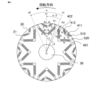
- 2 is a cross-sectional view of a rotor in the rotating electric machine according to the first embodiment.
- FIG. 2 is an enlarged cross-sectional view of a rotor in the rotating electric machine according to the first embodiment;
- 4 is a diagram showing magnetic flux vectors in the rotating electric machine according to the first embodiment;
- FIG. 4 is a diagram showing a no-load phase voltage waveform in the rotating electric machine according to the first embodiment;
- FIG. 4 is a diagram showing magnetic flux vectors in the rotating electric machine according to the first embodiment;
- FIG. 4 is a diagram showing magnetic flux vectors in the rotating electric machine according to the first embodiment;
- FIG. 4 is a diagram showing magnetic flux vectors in the rotating electric machine according to the first embodiment;
- FIG. 4 is a diagram showing magnetic flux vectors in the rotating electric machine according to the first embodiment;
- FIG. 5 is a diagram showing the characteristics of a composite torque in the rotating electric machine according to the first embodiment.
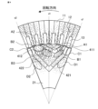
- FIG. 11 is an enlarged cross-sectional view of a rotor in a rotating electric machine according to a second embodiment.
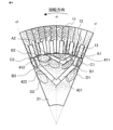
- FIG. 11 is an enlarged cross-sectional view of a rotor in a rotating electric machine according to a third embodiment.
- FIG. 13 is a diagram showing magnetic flux vectors in a rotating electric machine according to Embodiment 3.
- FIG. 13 is a diagram showing magnetic flux vectors in a rotating electric machine according to Embodiment 3.
- FIG. 13 is a diagram showing magnetic flux vectors in a rotating electric machine according to Embodiment 3.
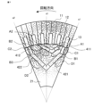
- FIG. 13 is an enlarged cross-sectional view of a rotor in a rotating electric machine according to a fourth embodiment.
- FIG. 13 is an enlarged cross-sectional view of a rotor in a rotating electric machine according to a fifth embodiment.
- FIG. 13 is an enlarged cross-sectional view of a rotor in a rotating electric machine according to a sixth embodiment.
- FIG. 13 is an enlarged cross-sectional view of a rotor in a rotating electric machine according to a seventh embodiment of the present invention.
- 13 is an enlarged cross-sectional view of a rotor in a rotating electric machine according to an eighth embodiment of the present invention.
- 13 is an enlarged cross-sectional view of a rotor in a rotating electric machine according to a ninth embodiment of the present invention.
- FIG. 13 is an enlarged cross-sectional view of a rotor in a rotating electric machine according to a tenth embodiment.
- FIG. 23 is an enlarged cross-sectional view of a rotor in a rotating electric machine according to an eleventh embodiment of the present invention.
- 23 is an enlarged cross-sectional view of a rotor in a rotating electric machine according to embodiment 12.
- FIG. 23 is an enlarged cross-sectional view of a rotor in a rotating electric machine according to embodiment 13.
- 23 is an enlarged cross-sectional view of a rotor in a rotating electric machine according to embodiment 15.
- FIG. 1 is a cross-sectional view of a rotating electric machine according to the first embodiment.
- FIG. 1 is a cross-sectional view in a direction perpendicular to a rotation axis described later.
- the rotating electric machine 1 according to the present embodiment is composed of a ring-shaped stator 10 and a ring-shaped rotor 20 arranged on the inner diameter side of the stator 10 with a gap therebetween.
- a cylindrical rotating shaft 30 is fixed to the center of the rotor 20.
- the stator 10 and the rotor 20 are arranged coaxially with the rotating shaft 30 as a common axis.
- the rotating electric machine according to the specification of the present disclosure will be described as rotating counterclockwise.
- the counterclockwise direction is referred to as the rotation side
- the clockwise direction is referred to as the counter-rotation side.
- the rotating electric machine according to the specification of the present disclosure is mainly rotated counterclockwise around the rotation axis, but may also be rotated clockwise depending on the application.
- the direction parallel to the rotating shaft 30 is called the axial direction
- the direction perpendicular to the rotating shaft 30 is called the radial direction
- the direction rotating around the rotating shaft 30 is called the circumferential direction.
- the inner diameter side is the direction approaching the rotating shaft 30 in the radial direction
- the outer diameter side is the direction moving away from the rotating shaft 30 in the radial direction.
- the stator 10 is composed of a circular ring-shaped back core 11, teeth 12 extending from the back core 11 toward the inner diameter side, and stator coils 13 arranged in slots surrounded by adjacent teeth 12 and the back core 11.
- the back core 11 and teeth 12 together form the stator core.
- 48 teeth 12 are evenly arranged in the circumferential direction, and a stator coil 13 is arranged in each of the 48 slots formed between the teeth 12.
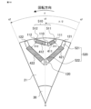
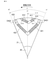
- FIG. 2 is a cross-sectional view of a rotor in a rotating electric machine according to this embodiment.
- FIG. 2 is a cross-sectional view in a direction perpendicular to the rotating shaft 30.
- the rotor 20 of this embodiment is composed of a ring-shaped rotor core 21 and magnets.
- the rotating shaft 30 is fixed to the center of the rotor core 21.
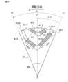
- the rotor core 21 is provided with a first layer magnet slot 510 formed in a V-shape with the spacing increasing toward the outer diameter side, and a second layer magnet slot 520 formed on the inner diameter side of the first layer magnet slot 510.
- the second layer magnet slot 520 is also formed in a V-shape like the first layer magnet slot 510.
- the first layer magnet 411 is inserted into the slot on the counter-rotation side of the first layer magnet slot 510, and the first layer magnet 412 is inserted into the slot on the rotation side.
- the second layer magnet 421 is inserted into the slot on the counter-rotation side of the second layer magnet slot 520, and the second layer magnet 422 is inserted into the slot on the rotation side.
- the first layer magnets 411, 412 and the second layer magnets 421, 422 are flat permanent magnets, oriented parallel to the short sides and all magnetized in the same direction. These four permanent magnets form one pole, and eight of these poles are arranged at equal intervals around the circumference. As shown in Figure 2, the magnetization directions of adjacent poles are set to be opposite to each other in the radial direction.
- the center of rotation of the rotor 20 is defined as point O.
- the point on the inner diameter side of one pole where the distance between the adjacent poles on the counter-rotation side is the shortest is defined as point P1
- the point on the inner diameter side of one pole where the distance between the adjacent poles on the rotation side is the shortest is defined as point P2.
- the points where the distance between the second layer magnets 421 and 422 is the smallest are points P1 and P2, respectively.
- the line segment connecting point P1 and point O is defined as line segment L1
- the line segment connecting point P2 and point O is defined as line segment L2.
- the bisector of line segments L1 and L2 is defined as line q1.
- the line that has an electrical angle of ⁇ from line q1 to the rotation side centered on point O is defined as line q2.
- One pole of the rotor 20 is the part surrounded by lines q1 and q2.
- the line that has an electrical angle of ⁇ /2 from line q1 to the rotation side centered on point O is defined as line d1.
- Straight line d1 is the dimensional centerline of one pole of rotor 20.
- FIG. 3 is an enlarged cross-sectional view of the rotor in the rotating electric machine according to this embodiment.
- FIG. 3 is an enlarged cross-sectional view of one pole of the rotor 20.
- the length of the first layer magnet 411 on the counter-rotation side along the magnet slot 510 is W411, and the length of the first layer magnet 412 on the rotation side along the magnet slot 510 is W412. In the rotating electric machine of this embodiment, W411 is shorter than W412.
- the point where the line extending the long side of the outer diameter of the first layer magnet 411 on the counter-rotation side intersects with the line extending the long side of the outer diameter of the first layer magnet 412 on the rotation side is defined as point P3, and the point where the line extending the long side of the inner diameter of the first layer magnet 411 on the counter-rotation side intersects with the line extending the long side of the inner diameter of the first layer magnet 412 on the rotation side is defined as point P4.
- the line segment connecting points P3 and P4 is defined as line segment L3. In the rotating electric machine of this embodiment, line segment L3 is located on the counter-rotation side of line d1.
- the shortest distance between the first layer magnet 411 on the counter-rotation side and the second layer magnet 421 on the counter-rotation side is D11
- the shortest distance between the first layer magnet 412 on the rotation side and the second layer magnet 422 on the rotation side is D12.
- the shortest circumferential distance between the first layer magnet slot 510 and the second layer magnet slot 520 on the counter-rotation side is D21
- the shortest circumferential distance between the first layer magnet slot 510 and the second layer magnet slot 520 on the rotation side is D22.
- at least one of the conditions that D12 is larger than D11 and D22 is larger than D21 is satisfied.
- the distance between the first layer magnet 411 and the second layer magnet 421 on the counter-rotation side becomes larger toward the inner diameter side
- the distance between the first layer magnet 411 and the second layer magnet 422 on the rotation side also becomes larger toward the inner diameter side.
- the angle of the first layer magnet slot 510 formed in a V shape is larger than the angle of the second layer magnet slot 520 formed in a V shape.
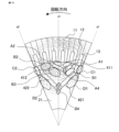
- FIG. 4 is a diagram showing magnetic flux vectors in a rotating electric machine according to this embodiment.
- FIG. 4 shows magnetic flux vectors under no-load conditions analyzed using the finite element method. Magnetic flux generated on the outer diameter side from the first layer magnet 411 on the counter-rotation side flows into the teeth 12 without changing direction in the region A1 between the first layer magnet 411 and the gap. Magnetic flux generated on the outer diameter side from the first layer magnet 412 on the rotation side also flows into the teeth 12 without changing direction in the region A2 between the first layer magnet 412 and the gap.
- region B1 the magnetic path of the rotor core 21 between the first-layer magnet 411 and the second-layer magnet 421, which have low permeance, is narrow, so the magnetic flux flows in the direction along the long side of the first-layer magnet 411. The magnetic flux then flows from there into the first-layer magnet 411 and the opposing teeth 12. Magnetic flux flows into the second layer magnet 421 on the counter-rotation side from the rotor core 21 that constitutes the adjacent pole on the counter-rotation side, via region D1 on the inner diameter side of the second layer magnet 421, in the direction of line q1. On the other hand, the magnetic flux vector passing through region C1 close to line q1 near the surface of the rotor core 21 is small.
- the magnetic flux vector that passes through region C2 close to line q2 near the surface of the rotor core 21 is small. Magnetic flux generated by both the second layer magnets 421 and 422 flows into region B3, and the magnetic flux that passes through region B3 flows into the first layer magnet 412 on the rotating side and region B2.
- FIG. 5 is a diagram showing the no-load phase voltage waveform in the rotating electric machine according to this embodiment.
- FIG. 5 shows the no-load phase voltage waveform analyzed using the finite element method.
- the horizontal axis is the rotor position shown in electrical angle
- the vertical axis is the relative value of the no-load phase voltage.
- the no-load phase voltage waveform has two asymmetric peaks with low voltage on the lagging side with respect to the pole center at rotor positions of approximately 120 degrees and 300 degrees electrical angle. This is because, as shown in FIG.
- Fig. 6 is a diagram showing magnetic flux vectors in a rotating electric machine according to this embodiment.
- Fig. 6 shows magnetic flux vectors obtained by analyzing, using the finite element method, the conditions under which an armature magnetomotive force of a current phase that maximizes the composite torque is applied to the stator coil, while no magnetomotive force is applied to the rotor magnet.
- the magnetic flux generated in the stator coil 13 flows from the teeth 12 into areas A1, B1, and C1 of the opposing rotor core 21.
- the magnetic flux that flows into area A1 passes through areas A2 and B2 and returns to the teeth 12.
- the direction of the magnetic flux in area A1 shown in Figure 6 is opposite to the direction of the magnetic flux in area A1 shown in Figure 4, and the two directions cancel each other out.
- the direction of the magnetic flux in area A2 shown in Figure 6 intersects with the direction of the magnetic flux in area A2 shown in Figure 4.
- the magnetic flux that flows into region B1 passes through regions B3 and B2 and returns to tooth 12.
- the direction of the magnetic flux in region B1 shown in FIG. 6 is opposite to the direction of the magnetic flux in region B1 shown in FIG. 4, and the directions cancel each other out.
- the direction of the magnetic flux in regions B2 and B3 shown in FIG. 6 is the same as the direction of the magnetic flux in regions B2 and B3 shown in FIG. 4, and the directions reinforce each other.
- the magnetic flux that flows into region C1 passes through regions D1, D2, and C2 and returns to tooth 12. While the magnetic flux vectors of regions C1 and C2 shown in FIG. 4 are small, the magnetic flux vectors of regions C1 and C2 shown in FIG. 6 are magnetic flux vectors that point in opposite directions, and regions C1 and C2 are effectively used as magnetic paths. The direction of the magnetic flux in regions D1 and D2 shown in FIG. 6 intersects with the direction of the magnetic flux in regions D1 and D2 shown in FIG. 4.
- FIG. 7 is a diagram showing magnetic flux vectors in a rotating electric machine according to this embodiment.
- FIG. 7 shows magnetic flux vectors obtained by analyzing the conditions under which the combined torque of the rotating electric machine is maximized using the finite element method.
- regions A1 and B1 the direction of the magnetic flux due to the magnet magnetomotive force and the direction of the magnetic flux due to the armature magnetomotive force are opposite to each other, so the amount of magnetic flux is small.
- regions A2, B2, and B3 the direction of the magnetic flux due to the magnet magnetomotive force and the direction of the magnetic flux due to the armature magnetomotive force are the same, so the amount of magnetic flux is large.
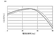
- Figure 8 is a diagram showing the characteristics of the composite torque in the rotating electric machine according to this embodiment.
- Figure 8 shows the results of an analysis using the finite element method of the change in the composite torque with respect to the current phase angle when the current value is constant in the rotating electric machine according to this embodiment.
- the horizontal axis is the current phase angle
- the vertical axis is the relative value of the composite torque.
- the composite torque is a torque obtained by combining the magnet torque and the reluctance torque.
- the solid line shows the composite torque of the rotating electric machine according to this embodiment
- the dashed line shows the composite torque of the rotating electric machine according to the comparative example.
- the comparative example rotating electric machine is a rotating electric machine having a rotor in which the shape of the first layer magnet slot 510 and the shapes of the first layer magnets 411, 421 are symmetrical with respect to the line d1 in the rotor of the rotating electric machine shown in Figure 3.
- the current phase angle at which the composite torque of the rotating electric machine of this embodiment reaches its peak is smaller than the current phase angle at which the composite torque of the rotating electric machine of the comparative example reaches its peak.
- the peak value of the composite torque of the rotating electric machine of this embodiment is greater than the peak value of the composite torque of the rotating electric machine of the comparative example.
- the magnet torque reaches a positive peak value when the current phase angle is 0 degrees.
- the positional relationship between the stator and rotor is such that the magnetic resistance from the q-axis is at a minimum, so the reluctance torque is zero (the d-axis current is zero).
- the positional relationship between the stator and rotor is such that the magnetic resistance from the d-axis is at a minimum, so the reluctance torque is zero (the q-axis current is zero).
- the arrangement of the magnets in the rotor can be made asymmetric and the current phase angle at which the magnetic resistance is maximum or minimum can be shifted from the current phase angle of 0 degrees or 90 degrees defined in the rotating electric machine of the comparative example, the peak position of the reluctance torque can be changed.
- a reluctance torque equal to or greater than that of the rotating electric machine of the comparative example is generated when the current phase angle is 0 degrees, and a negative reluctance torque is generated when the current phase angle is 90 degrees, so that the reluctance torque can be advanced relative to the current phase angle.
- the positive peak value of the composite torque becomes larger because the current phase angle when the magnet torque reaches its positive peak value and the current phase angle when the reluctance torque reaches its positive peak value approach each other.
- the first layer magnets are arranged asymmetrically toward the counter-rotation side, and the length W411 of the long side of the first layer magnet 411 on the counter-rotation side is made shorter than the length W412 of the long side of the first layer magnet 412 on the rotating side.
- D12 which relates to the width of region B2 where the magnet magnetomotive force and the armature magnetomotive force reinforce each other, is made larger than D11, which relates to the width of region B1 where the magnet magnetomotive force and the armature magnetomotive force weaken each other.
- the rotating electric machine of this embodiment can suppress torque reduction due to magnetic saturation in the center of the magnetic pole and improve peak torque.
- the magnet slots formed in a V shape are connected between the magnet slots on the counter-rotation side and the magnet slots on the rotation side, but the magnet slots on the counter-rotation side and the magnet slots on the rotation side may be separated on the inner diameter side.
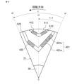
- Fig. 9 is an enlarged cross-sectional view of a rotor in a rotating electric machine according to embodiment 2.
- Fig. 9 is an enlarged cross-sectional view of one pole of the rotor.
- the configuration of the rotating electric machine according to this embodiment is similar to the configuration of the rotating electric machine described in embodiment 1, except for the structure of the rotor shown in Fig. 9.
- the rotor of this embodiment has three layers of magnet slots.
- the rotor core 21 of this embodiment has a first layer magnet slot 510 formed in a V-shape with the spacing increasing toward the outer diameter side, a second layer magnet slot 520 formed on the inner diameter side of the first layer magnet slot 510, and a third layer magnet slot 530 formed on the inner diameter side of the second layer magnet slot 520.
- the second layer magnet slot 520 and the third layer magnet slot 530 are also formed in a V-shape like the first layer magnet slot 510.
- the first layer magnet 411 is inserted in the slot on the counter-rotation side of the first layer magnet slot 510, and the first layer magnet 412 is inserted in the slot on the rotation side.
- first-layer magnets 411, 412, second-layer magnets 421, 422, and third-layer magnets 431, 432 are flat permanent magnets oriented parallel to their short sides and all magnetized in the same direction. These six permanent magnets form one pole, and eight of these poles are arranged at equal intervals in the circumferential direction. The magnetization directions of adjacent poles are set to be opposite to each other in the radial direction.
- the center of rotation of the rotor 20 is defined as point O.
- the point on the inner diameter side of the pole 1 where the distance between the adjacent poles on the counter-rotation side is the shortest is defined as point P1
- the point on the inner diameter side of the pole 1 where the distance between the adjacent poles on the rotation side is the shortest is defined as point P2.
- the points where the distance between the third layer magnets 431 and 432 is the smallest are points P1 and P2, respectively.
- the line segment connecting point P1 and point O is defined as line segment L1
- the line segment connecting point P2 and point O is defined as line segment L2.
- the bisector of line segments L1 and L2 is defined as line q1.
- the line that has an electrical angle of ⁇ from line q1 toward the rotation side centered on point O is defined as line q2.
- One pole of the rotor 20 is the part surrounded by lines q1 and q2.
- the line that has an electrical angle of ⁇ /2 from line q1 toward the rotation side centered on point O is defined as line d1.
- Straight line d1 is the dimensional centerline of one pole of rotor 20.
- the point where the line extending the long side of the outer diameter of the first layer magnet 411 on the counter-rotation side intersects with the line extending the long side of the outer diameter of the first layer magnet 412 on the rotation side is defined as point P3, and the point where the line extending the long side of the inner diameter of the first layer magnet 411 on the rotation side intersects with the line extending the long side of the inner diameter of the first layer magnet 412 on the counter-rotation side is defined as point P4.
- the line segment connecting points P3 and P4 is defined as line segment L3. In the rotating electric machine of this embodiment, line segment L3 is located on the counter-rotation side of line d1.
- the length of the long side of the first layer magnet 411 on the rotating side is W411, and the length of the long side of the first layer magnet 412 on the counter-rotating side is W412. In the rotating electric machine of this embodiment, W411 is shorter than W412.
- the shortest distance between the first layer magnet 411 on the counter-rotation side and the second layer magnet 421 on the counter-rotation side is D11
- the shortest distance between the first layer magnet 412 on the rotation side and the second layer magnet 422 on the rotation side is D12.
- the shortest circumferential distance between the first layer magnet slot 510 and the second layer magnet slot 520 on the counter-rotation side is D21
- the shortest circumferential distance between the first layer magnet slot 510 and the second layer magnet slot 520 on the rotation side is D22.
- at least one of the conditions that D12 is larger than D11 and D22 is larger than D21 is satisfied.
- the distance between the first layer magnet 411 and the second layer magnet 421 on the counter-rotation side becomes larger toward the inner diameter side
- the distance between the first layer magnet 411 and the second layer magnet 422 on the rotation side also becomes larger toward the inner diameter side.
- the angle of the first layer magnet slot 510 formed in a V shape is larger than the angle of the second layer magnet slot 520 formed in a V shape.
- the angle of the third layer magnet slot 530 formed in a V shape is the same as the angle of the second layer magnet slot 520 formed in a V shape.
- the angle of the first layer magnet slot formed in a V shape is larger than the angles of the magnet slots of the other layers formed in a V shape.
- the first layer magnets are arranged asymmetrically toward the counter-rotation side, and the length W411 of the long side of the first layer magnet 411 on the counter-rotation side is made shorter than the length W412 of the long side of the first layer magnet 412 on the rotating side, and D12, which relates to the width of the region where the magnet magnetomotive force and the armature magnetomotive force reinforce each other, is made larger than D11, which relates to the width of the region where the magnet magnetomotive force and the armature magnetomotive force weaken each other, and further, the distance between the first layer magnet 412 on the rotating side and the second layer magnet 422 on the rotating side, which is the region where the magnet magnetomotive force and the armature magnetomotive force reinforce each other, is made larger toward the inner diameter side.
- the rotating electric machine of this embodiment can suppress torque reduction due to magnetic saturation in the center of the magnetic pole and improve peak torque.
- Fig. 10 is an enlarged cross-sectional view of a rotor in a rotating electric machine according to embodiment 3.
- Fig. 10 is an enlarged cross-sectional view of one pole of the rotor.
- the configuration of the rotating electric machine according to this embodiment is similar to the configuration of the rotating electric machine described in embodiment 1, except for the structure of the rotor shown in Fig. 10.
- the first layer magnet slot 510 which is formed in a V-shape with the spacing increasing toward the outer diameter side, is composed of the first layer anti-rotation side magnet slot 511 and the rotation side magnet slot 512.
- a central bridge 110 which is part of the rotor core 21, is provided between the anti-rotation side magnet slot 511 and the rotation side magnet slot 512.
- the second layer magnet slot 520 which is formed in a V-shape with the spacing increasing toward the outer diameter side, is composed of the second layer anti-rotation side magnet slot 521 and the rotation side magnet slot 522.
- a central bridge 120 which is part of the rotor core 21, is provided between the anti-rotation side magnet slot 521 and the rotation side magnet slot 522.
- peripheral bridges 111, 112 which are part of the rotor core 21, are provided on the outer periphery of the counter-rotation side magnet slot 511 and the rotating side magnet slot 512 of the first layer, respectively, and peripheral bridges 121, 122, which are part of the rotor core 21, are provided on the outer periphery of the counter-rotation side magnet slot 521 and the rotating side magnet slot 522 of the second layer, respectively.
- the configuration of the rotating electric machine of this embodiment is the same as that of embodiment 1, except for the shape of the magnet slot. That is, in the rotating electric machine of this embodiment, the arrangement of the first layer magnets is asymmetrical and is closer to the counter-rotation side, the length of the long side of the first layer magnet 411 on the counter-rotation side is shorter than the length of the long side of the first layer magnet 412 on the rotating side, D12, which relates to the width of the region where the magnet magnetomotive force and the armature magnetomotive force reinforce each other, is made larger than D11, which relates to the width of the region where the magnet magnetomotive force and the armature magnetomotive force weaken each other, and further, the distance between the first layer magnet 412 on the rotating side and the second layer magnet 422 on the rotating side, which are the regions where the magnet magnetomotive force and the armature magnetomotive force reinforce each other, is made larger toward the inner diameter side.
- the rotating electric machine of this embodiment can suppress torque
- the rotor is provided with an outer bridge and a center bridge, which reduces the stress concentration on the outer bridge caused by centrifugal force during rotation, thereby increasing the allowable rotation speed.
- FIG. 11 is a diagram showing magnetic flux vectors in a rotating electric machine according to this embodiment.
- FIG. 11 shows magnetic flux vectors under no-load conditions analyzed using the finite element method.
- a portion of the magnetic flux generated on the outer diameter side from the first layer magnet 411 on the counter-rotation side flows into region A4 of the central bridge 110.
- a portion of the magnetic flux generated on the outer diameter side from the first layer magnet 412 on the rotation side also flows into region A4 of the central bridge 110.
- a portion of the magnetic flux generated on the outer diameter side from the second layer magnet 421 on the counter-rotation side flows into region B4 of the central bridge 120.
- a portion of the magnetic flux generated on the outer diameter side from the second layer magnet 422 on the rotation side also flows into region B4 of the central bridge 120.
- the magnetic flux flowing in regions A1, A2, B1, B2, and B3 is reduced compared to FIG. 4 shown in embodiment 1.
- Fig. 12 is a diagram showing magnetic flux vectors in a rotating electric machine according to this embodiment.
- Fig. 12 shows magnetic flux vectors obtained by analyzing, using the finite element method, the conditions under which an armature magnetomotive force of a current phase that maximizes the composite torque is applied to the stator coil, while no magnetomotive force is applied to the rotor magnet.
- the magnetic flux generated in the stator coil 13 flows from the teeth 12 into areas A1, A4, B1, and C1 of the opposing rotor core 21.
- a portion of the magnetic flux that flows into areas A1 and A4 passes through areas B4, D2, and C2, and returns to the teeth 12.
- the magnetic flux flowing in areas A2, B2, and B3 is reduced compared to FIG. 6 shown in embodiment 1.
- FIG. 13 is a diagram showing magnetic flux vectors in a rotating electric machine according to this embodiment.
- FIG. 13 shows magnetic flux vectors obtained by analyzing the conditions under which the combined torque of the rotating electric machine is maximized using the finite element method.
- the leakage magnetic flux mentioned above does not contribute to torque, but the magnetic flux increases further in the center of the rotor where areas A4 and B4 are located.
- This increased magnetic flux increases the magnetic flux density in the center of the rotor, and when this increases in combination with the effective magnetic flux and causes magnetic saturation, the effective magnetic flux decreases, leading to a decrease in torque.
- the arrangement of areas A4 and B4 makes it easier for magnetic saturation to occur in the center of the rotor, so it is also effective in the rotating electric machine of this embodiment to increase the distance between the first layer magnet 412 and the second layer magnet 422 on the rotating side as it moves toward the inner diameter side.
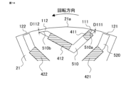
- Fig. 14 is an enlarged cross-sectional view of a rotor in a rotating electric machine according to embodiment 4.
- Fig. 14 is an enlarged cross-sectional view of the outer periphery of one pole of the rotor.
- the configuration of the rotating electric machine according to this embodiment is the same as the configuration of the rotating electric machine described in embodiment 1, except for the rotor structure shown in Fig. 14.
- the arrangement of the first layer magnets is asymmetrical and closer to the counter-rotation side, the length of the long side of the first layer magnet on the counter-rotation side is shorter than the length of the long side of the first layer magnet on the rotating side, the width of the region where the magnet magnetomotive force and the armature magnetomotive force strengthen each other is made larger than the width of the region where the magnet magnetomotive force and the armature magnetomotive force weaken each other, and further, the gap between the first layer magnet on the rotating side and the second layer magnet on the rotating side is made larger toward the inner diameter side.
- the outer bridge 111 on the counter-rotation side is between the outermost surface 510a on the counter-rotation side of the first layer magnet slot 510 and the outer surface 21a of the rotor core 21 that faces it.
- the outer bridge 112 on the rotation side is between the outermost surface 510b on the rotation side of the first layer magnet slot 510 and the outer surface 21a of the rotor core 21 that faces it.
- the radial width D111 of the outer bridge 111 on the counter-rotation side is set smaller than the radial width D112 of the outer bridge 112 on the rotation side. Since the length of the long side of the first layer magnet 411 on the counter-rotation side is shorter than the length of the long side of the first layer magnet 412 on the rotation side, the mass of the first layer magnet 411 on the counter-rotation side is smaller than the mass of the first layer magnet 412 on the rotation side. Therefore, the stress applied to the outer bridge 111 by the centrifugal force during rotation is smaller than the stress applied to the outer bridge 112.
- the radial width D111 of the outer bridge 111 on the counter-rotation side is made smaller than the radial width D112 of the outer bridge 112 on the rotation side, thereby reducing the leakage magnetic flux of the outer bridge.
- Fig. 15 is an enlarged cross-sectional view of a rotor in a rotating electric machine according to embodiment 5.
- Fig. 15 is an enlarged cross-sectional view of one pole of the rotor.
- the configuration of the rotating electric machine according to this embodiment is the same as the configuration of the rotating electric machine described in embodiment 1, except for the rotor structure shown in Fig. 15.
- the arrangement of the first layer magnets is asymmetrical and closer to the counter-rotation side, the length of the long side of the first layer magnet on the counter-rotation side is shorter than the length of the long side of the first layer magnet on the rotating side, the width of the region where the magnet magnetomotive force and the armature magnetomotive force strengthen each other is made larger than the width of the region where the magnet magnetomotive force and the armature magnetomotive force weaken each other, and further, the gap between the first layer magnet on the rotating side and the second layer magnet on the rotating side is made larger toward the inner diameter side.
- the thickness D411 of the short side of the first layer magnet 411 on the counter-rotation side is set to be greater than the thickness D412 of the short side of the first layer magnet 412 on the rotation side.
- Increasing the amount of magnets is an effective way to increase torque, but increasing the amount of magnets reduces the area with low magnetic resistance and increases the magnet magnetomotive force, which causes magnetic saturation and inhibits torque increase. Therefore, making the thickness D411 of the short side of the first layer magnet 411 on the counter-rotation side, which is the area where the magnet magnetomotive force and the armature magnetomotive force weaken each other, larger than the thickness D412 of the short side of the first layer magnet 412 on the rotating side, which is the area where the magnet magnetomotive force and the armature magnetomotive force strengthen each other, can alleviate the inhibition of torque increase caused by magnetic saturation.
- the effect of weakening the magnet magnetic flux by the armature magnetic flux can be more effectively utilized.
- a similar effect can be obtained by making the thicknesses of the first layer magnets 411 and 412 the same and using a magnetic material with a higher residual magnetic flux density for the magnetic material of the first layer magnet 411 on the counter-rotation side than the magnetic material of the first layer magnet 412 on the rotating side.
- Fig. 16 is an enlarged cross-sectional view of a rotor in a rotating electric machine according to embodiment 6.
- Fig. 16 is an enlarged cross-sectional view of one pole of the rotor.
- the configuration of the rotating electric machine according to this embodiment is the same as the configuration of the rotating electric machine described in embodiment 1, except for the rotor structure shown in Fig. 16.
- the arrangement of the first layer magnets is asymmetrical and closer to the counter-rotation side, the length of the long side of the first layer magnet on the counter-rotation side is shorter than the length of the long side of the first layer magnet on the rotating side, the width of the region where the magnet magnetomotive force and the armature magnetomotive force strengthen each other is made larger than the width of the region where the magnet magnetomotive force and the armature magnetomotive force weaken each other, and further, the gap between the first layer magnet on the rotating side and the second layer magnet on the rotating side is made larger toward the inner diameter side.
- the thickness D421 of the short side of the second layer magnet 421 on the counter-rotation side is set to be greater than the thickness D422 of the short side of the second layer magnet 422 on the rotation side.
- Increasing the amount of magnets is an effective way to increase torque, but increasing the amount of magnets reduces the area with low magnetic resistance and increases the magnet magnetomotive force, which causes magnetic saturation and inhibits torque increase. Therefore, making the thickness D421 of the short side of the second layer magnet 421 on the counter-rotation side, which is the area where the magnet magnetomotive force and the armature magnetomotive force weaken each other, larger than the thickness D422 of the short side of the second layer magnet 422 on the rotating side, which is the area where the magnet magnetomotive force and the armature magnetomotive force strengthen each other, can alleviate the inhibition of torque increase caused by magnetic saturation.
- the effect of weakening the magnet magnetic flux by the armature magnetic flux can be more effectively utilized.
- the same effect can be obtained by making the thicknesses of the second layer magnets 421 and 422 the same and using a magnetic material with a higher residual magnetic flux density for the magnetic material of the second layer magnet 421 on the counter-rotation side than for the magnetic material of the second layer magnet 422 on the rotating side.
- Fig. 17 is an enlarged cross-sectional view of a rotor in a rotating electric machine according to embodiment 7.
- Fig. 17 is an enlarged cross-sectional view of one pole of the rotor.
- the configuration of the rotating electric machine according to this embodiment is the same as the configuration of the rotating electric machine described in embodiment 1, except for the rotor structure shown in Fig. 17.
- the arrangement of the first layer magnets is asymmetrical and closer to the counter-rotation side, the length of the long side of the first layer magnets on the counter-rotation side is shorter than the length of the long side of the first layer magnets on the rotation side, the width of the region where the magnet magnetomotive force and the armature magnetomotive force strengthen each other is made larger than the width of the region where the magnet magnetomotive force and the armature magnetomotive force weaken each other, and further, the gap between the first layer magnets on the rotation side and the second layer magnets on the rotation side is made larger toward the inner diameter side.
- the first layer magnet 412 on the rotating side is composed of two split magnets 412a and 412b.
- the shapes of the split magnets 412a and 412b are the same as the shape of the first layer magnet 411 on the counter-rotating side.
- magnets of the same shape can be used as the first layer magnets, allowing magnets to be manufactured efficiently. Also, compared to when magnets of different shapes are used as the first layer magnets, the complexity of identifying magnets and the risk of handling errors can be reduced. Furthermore, by configuring the first layer magnet on the rotating side from two split magnets, the path of the eddy currents becomes longer and the magnetic resistance becomes higher, reducing the losses generated in the first layer magnet on the rotating side.
- Fig. 18 is an enlarged cross-sectional view of a rotor in a rotating electric machine according to embodiment 8.
- Fig. 18 is an enlarged cross-sectional view of one pole of the rotor.
- the configuration of the rotating electric machine according to this embodiment is the same as the configuration of the rotating electric machine described in embodiment 1, except for the rotor structure shown in Fig. 18.
- the arrangement of the first layer magnets is asymmetrical and closer to the counter-rotation side, the length of the long side of the first layer magnets on the counter-rotation side is shorter than the length of the long side of the first layer magnets on the rotating side, the width of the region where the magnet magnetomotive force and the armature magnetomotive force strengthen each other is made larger than the width of the region where the magnet magnetomotive force and the armature magnetomotive force weaken each other, and further, the gap between the first layer magnets on the rotating side and the second layer magnets on the rotating side is made larger toward the inner diameter side.
- the first layer magnet 411 on the counter-rotation side is composed of two split magnets 411a and 411b
- the first layer magnet 412 on the rotation side is composed of three split magnets 412a, 412b, and 412c.
- the split magnets 411a, 411b, 412a, 412b, and 412c all have the same shape.
- the first layer magnet 411 on the counter-rotation side and the first layer magnet 412 on the rotation side may be composed of four or more split magnets of the same shape, other than as shown in FIG. 18. In this case, the number of split magnets constituting the first layer magnet 411 on the counter-rotation side should be less than the number of split magnets constituting the first layer magnet 412 on the rotation side.
- the first layer magnets In a rotating electric machine configured in this way, multiple magnets of the same shape can be used as the first layer magnets, allowing magnets to be manufactured efficiently. Also, compared to using magnets of different shapes as the first layer magnets, the complexity of identifying magnets and the risk of handling errors can be reduced. Furthermore, by configuring the first layer magnet from multiple split magnets, the path of eddy currents becomes longer and the magnetic resistance becomes higher, allowing the loss generated in the first layer magnet to be reduced.
- Fig. 19 is an enlarged cross-sectional view of a rotor in a rotating electric machine according to embodiment 9.
- Fig. 19 is an enlarged cross-sectional view of one pole of the rotor.
- the configuration of the rotating electric machine according to this embodiment is the same as the configuration of the rotating electric machine described in embodiment 1, except for the rotor structure shown in Fig. 19.
- the arrangement of the first layer magnets is asymmetrical and closer to the counter-rotation side, the length of the long side of the first layer magnets on the counter-rotation side is shorter than the length of the long side of the first layer magnets on the rotation side, the width of the region where the magnet magnetomotive force and the armature magnetomotive force strengthen each other is made larger than the width of the region where the magnet magnetomotive force and the armature magnetomotive force weaken each other, and further, the gap between the first layer magnets on the rotation side and the second layer magnets on the rotation side is made larger toward the inner diameter side.
- the second layer magnet 421 on the counter-rotation side is composed of two split magnets 421a and 421b.
- the shapes of the split magnets 421a and 421b are the same as the shape of the second layer magnet 422 on the rotation side.
- magnets of the same shape can be used as the second-layer magnets, allowing magnets to be manufactured efficiently. Also, compared to when magnets of different shapes are used as the second-layer magnets, the complexity of identifying magnets and the risk of handling errors can be reduced. Furthermore, by configuring the second-layer magnet on the counter-rotation side from two split magnets, the path of the eddy currents becomes longer and the magnetic resistance becomes higher, allowing the loss generated in the second-layer magnet on the counter-rotation side to be reduced.
- Fig. 20 is an enlarged cross-sectional view of a rotor in a rotating electric machine according to embodiment 10.
- Fig. 20 is an enlarged cross-sectional view of one pole of the rotor.
- the configuration of the rotating electric machine according to this embodiment is the same as the configuration of the rotating electric machine described in embodiment 1, except for the rotor structure shown in Fig. 20.
- the arrangement of the first layer magnets is asymmetrical and closer to the counter-rotation side, the length of the long side of the first layer magnets on the counter-rotation side is shorter than the length of the long side of the first layer magnets on the rotating side, the width of the region where the magnetomotive force of the magnet and the armature magnetomotive force strengthen each other is made larger than the width of the region where the magnetomotive force of the magnet and the armature magnetomotive force weaken each other, and further, the gap between the first layer magnets on the rotating side and the second layer magnets on the rotating side is made larger toward the inner diameter side.
- the first layer magnet 412 on the rotating side is composed of two divided magnets 412a and 412b.
- the second layer magnet 421 on the counter-rotating side is composed of four divided magnets 421a, 421b, 421c, and 421d.
- the second layer magnet 422 on the rotating side is composed of four divided magnets 422a, 422b, 422c, and 422d.
- the shapes of two or more of the divided magnets are set to the same shape.
- the shapes of the magnets that are different are set to shapes that are easily distinguishable. In the example shown in Figure 20, the shapes of all the magnets other than divided magnet 412b are set to the same shape.
- the first layer magnet 411 and the divided magnets 412a, 421a, 421b, 421c, 421d, 422a, 422b, 422c, and 422d all have the same shape.
- the first layer magnet 412 and the second layer magnets 421 and 422 on the rotating side may be composed of five or more divided magnets of the same shape, other than those shown in FIG. 20.
- first and second layer magnets In a rotating electric machine configured in this manner, multiple magnets of the same shape can be used as the first and second layer magnets, allowing magnets to be manufactured efficiently. In addition, because magnets of different shapes are shaped to be easily distinguished, the complexity of distinguishing magnets and handling errors can be reduced. Furthermore, by configuring the first and second layer magnets from multiple split magnets, the path of eddy currents becomes longer and the magnetic resistance increases, allowing losses generated in the first and second layer magnets to be reduced.
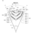
- Fig. 21 is an enlarged cross-sectional view of a rotor in a rotating electric machine according to an eleventh embodiment.
- Fig. 21 is an enlarged cross-sectional view of one pole of the rotor.
- the configuration of the rotating electric machine according to this embodiment is the same as the configuration of the rotating electric machine described in the first embodiment, except for the structure of the rotor shown in Fig. 21.
- the arrangement of the first layer magnets is asymmetric and closer to the counter-rotation side, the length of the long side of the first layer magnets on the counter-rotation side is shorter than the length of the long side of the first layer magnets on the rotation side, the width of the region where the magnet magnetomotive force and the armature magnetomotive force strengthen each other is made larger than the width of the region where the magnet magnetomotive force and the armature magnetomotive force weaken each other, and further, the gap between the first layer magnets on the rotation side and the second layer magnets on the rotation side is made larger toward the inner diameter side.
- the rotating electric machine of this embodiment has a first layer magnet slot 510 formed in a V-shape with the spacing increasing toward the outer diameter side, a second layer magnet slot 520 formed on the inner diameter side of the first layer magnet slot 510, and a third layer magnet slot 530 formed on the inner diameter side of the second layer magnet slot 520.
- the third layer magnet slot 530 has a bent slot on the counter-rotation side.
- a third layer magnet 431 is inserted into the slot on the counter-rotation side of the third layer magnet slot 530, and a third layer magnet 432 is inserted into the slot on the rotation side.
- the first layer magnet 412 on the rotating side is composed of two divided magnets 412a and 412b.
- the second layer magnet 421 on the counter-rotation side is composed of three divided magnets 421a, 421b, and 421c.
- the second layer magnet 422 on the rotating side is composed of two divided magnets 422a and 422b.
- the third layer magnet 431 on the counter-rotation side is composed of seven divided magnets 431a, 431b, 431c, 431d, 431e, 431f, and 431g.
- the third layer magnet 432 on the rotating side is composed of four divided magnets 432a, 432b, 432c, and 432d.
- the first layer magnet, second layer magnet, and third layer magnet may be composed of five or more divided magnets in addition to those shown in FIG. 21.
- the number of split magnets that make up the magnet on the counter-rotation side can be configured to be different from the number of split magnets that make up the magnet on the rotation side.
- the shapes of two or more magnets are set to be the same.
- the shapes of the magnets that are different are set to be easily distinguishable.
- first, second and third layer magnets In a rotating electric machine configured in this manner, multiple magnets of the same shape can be used as the first, second and third layer magnets, allowing magnets to be manufactured efficiently. In addition, because magnets of different shapes are easily distinguishable, the complexity of distinguishing magnets and handling errors can be reduced. Furthermore, by configuring the first, second and third layer magnets from multiple split magnets, the path of eddy currents becomes longer and the magnetic resistance increases, allowing the losses generated in the first, second and third layer magnets to be reduced.
- Fig. 22 is an enlarged cross-sectional view of a rotor in a rotating electric machine according to embodiment 12.
- Fig. 22 is an enlarged cross-sectional view of one pole of the rotor.
- the configuration of the rotating electric machine according to this embodiment is the same as the configuration of the rotating electric machine described in embodiment 1, except for the rotor structure shown in Fig. 22.
- the arrangement of the first layer magnets is asymmetrical and closer to the counter-rotation side, the length of the long side of the first layer magnets on the counter-rotation side is shorter than the length of the long side of the first layer magnets on the rotation side, the width of the region where the magnetomotive force of the magnet and the armature magnetomotive force strengthen each other is made larger than the width of the region where the magnetomotive force of the magnet and the armature magnetomotive force weaken each other, and further, the distance between the first layer magnets on the rotation side and the second layer magnets on the rotation side is made larger toward the inner diameter side.
- the length of the long side of the second layer magnet 421 on the counter-rotation side is W421, and the length of the long side of the second layer magnet 422 on the rotation side is W422.
- W422 is shorter than W421.
- the shortest distance between the first layer magnet 411 on the counter-rotation side and the second layer magnet 421 on the counter-rotation side is D11
- the shortest distance between the first layer magnet 412 on the rotation side and the second layer magnet 422 on the rotation side is D12.
- D12 is larger than D11.
- the distance between the first layer magnet 412 on the rotation side and the second layer magnet 422 on the rotation side becomes larger as it goes toward the inner diameter side.
- Increasing the amount of magnets is an effective way to increase torque, but increasing the amount of magnets reduces the area of low magnetic resistance and increases the magnet magnetomotive force, which causes magnetic saturation and inhibits torque increase. Therefore, in order to increase the amount of magnets on the counter-rotation side, where the magnet magnetomotive force and armature magnetomotive force weaken each other, compared to the amount of magnets on the rotation side, where the magnet magnetomotive force and armature magnetomotive force strengthen each other, making the length W422 of the long side of the second layer magnet 422 on the rotation side shorter than the length W421 of the long side of the second layer magnet 421 on the counter-rotation side can alleviate the inhibition of torque increase caused by magnetic saturation. Therefore, in a rotating electric machine configured in this way, the effect of weakening the magnet magnetic flux by the armature magnetic flux can be more effectively utilized.
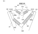
- Fig. 23 is an enlarged cross-sectional view of a rotor in a rotating electric machine according to embodiment 13.
- Fig. 23 is an enlarged cross-sectional view of the outer periphery of one pole of the rotor.
- the configuration of the rotating electric machine according to this embodiment is the same as the configuration of the rotating electric machine described in embodiment 1, except for the rotor structure shown in Fig. 23.
- the arrangement of the first layer magnets is asymmetrical and closer to the counter-rotation side, the length of the long side of the first layer magnet on the counter-rotation side is shorter than the length of the long side of the first layer magnet on the rotating side, the width of the region where the magnet magnetomotive force and the armature magnetomotive force strengthen each other is made larger than the width of the region where the magnet magnetomotive force and the armature magnetomotive force weaken each other, and further, the gap between the first layer magnet on the rotating side and the second layer magnet on the rotating side is made larger toward the inner diameter side.
- the outermost surface 520a of the second-layer magnet slot 520 on the counter-rotation side and the outermost surface 21a of the rotor core 21 facing it form the counter-rotation side outer bridge 121.
- the outermost surface 520b of the second-layer magnet slot 520 on the rotation side and the outermost surface 21a of the rotor core 21 facing it form the rotation side outer bridge 122.
- the length of the long side of the second-layer magnet 421 on the counter-rotation side is longer than the length of the long side of the second-layer magnet 422 on the rotation side, so the mass of the second-layer magnet 421 on the counter-rotation side is heavier than the mass of the second-layer magnet 422 on the rotation side.
- the stress applied to the outer bridge 122 by the centrifugal force during rotation is smaller than the stress applied to the outer bridge 121.
- the radial width D122 of the outer bridge 122 on the rotation side is set smaller than the radial width D121 of the outer bridge 121 on the counter-rotation side.
- the radial width D121 of the outer periphery bridge 121 on the counter-rotation side is set smaller than the radial width D122 of the outer periphery bridge 122 on the rotation side, so that leakage magnetic flux of the outer periphery bridge can be reduced.
- Fig. 24 is an enlarged cross-sectional view of a rotor in a rotating electric machine according to embodiment 14.
- Fig. 24 is an enlarged cross-sectional view of one pole of the rotor.
- the configuration of the rotating electric machine according to this embodiment is the same as the configuration of the rotating electric machine described in embodiment 1, except for the rotor structure shown in Fig. 24.
- the arrangement of the first layer magnets is asymmetrical and closer to the counter-rotation side, the length of the long side of the first layer magnet on the counter-rotation side is shorter than the length of the long side of the first layer magnet on the rotating side, the width of the region where the magnet magnetomotive force and the armature magnetomotive force strengthen each other is made larger than the width of the region where the magnet magnetomotive force and the armature magnetomotive force weaken each other, and further, the gap between the first layer magnet on the rotating side and the second layer magnet on the rotating side is made larger toward the inner diameter side.
- the thickness D411 of the short side of the first layer magnet 411 on the counter-rotation side is set to be larger than the thickness D412 of the short side of the first layer magnet 412 on the rotation side.
- the length W422 of the long side of the second layer magnet 422 on the rotation side is set to be shorter than the length W421 of the long side of the second layer magnet 421 on the counter-rotation side.
- the shortest distance D11 between the first layer magnet 411 and the second layer magnet 421 on the counter-rotation side is set to be smaller than the shortest distance D12 between the first layer magnet 412 and the second layer magnet 422 on the rotation side.
- Increasing the amount of magnets is an effective way to increase torque, but increasing the amount of magnets reduces the area of low magnetic resistance and increases the magnet magnetomotive force, which causes magnetic saturation and inhibits torque increase. Therefore, making the thickness D411 of the short side of the first layer magnet 411 on the counter-rotation side, which is the area where the magnet magnetomotive force and the armature magnetomotive force weaken each other, larger than the thickness D412 of the short side of the first layer magnet 412 on the rotation side, which is the area where the magnet magnetomotive force and the armature magnetomotive force strengthen each other, and making the length W422 of the long side of the second layer magnet 422 on the rotation side shorter than the length W421 of the long side of the second layer magnet 421 on the counter-rotation side, can alleviate the inhibition of torque increase caused by magnetic saturation.
- the effect of weakening the magnet magnetic flux by the armature magnetic flux can be more effectively utilized.
- the same effect can be achieved by making the first layer magnets 411 and 412 the same thickness and using a magnetic material for the first layer magnet 411 on the counter-rotation side that has a higher residual magnetic flux density than the magnetic material for the first layer magnet 412 on the rotation side.
- the arrangement of the first layer magnets is asymmetrical and closer to the counter-rotation side, the length of the long side of the first layer magnet on the counter-rotation side is shorter than the length of the long side of the first layer magnet on the rotating side, the width of the region where the magnet magnetomotive force and the armature magnetomotive force strengthen each other is made larger than the width of the region where the magnet magnetomotive force and the armature magnetomotive force weaken each other, and further, the gap between the first layer magnet on the rotating side and the second layer magnet on the rotating side is made larger toward the inner diameter side.
- the thickness D421 of the short side of the second layer magnet 421 on the counter-rotation side is set to be larger than the thickness D422 of the short side of the second layer magnet 422 on the rotation side.
- the length W422 of the long side of the second layer magnet 422 on the rotation side is set to be shorter than the length W421 of the long side of the second layer magnet 421 on the counter-rotation side.
- the shortest distance D11 between the first layer magnet 411 on the counter-rotation side and the second layer magnet 421 on the counter-rotation side is set to be smaller than the shortest distance D12 between the first layer magnet 412 on the rotation side and the second layer magnet 422 on the rotation side.
- the thickness D421 of the short side of the second layer magnet 421 on the counter-rotation side is made larger than the thickness D422 of the short side of the second layer magnet 422 on the rotation side, and the length W422 of the long side of the second layer magnet 422 on the rotation side is made shorter than the length W421 of the long side of the second layer magnet 421 on the counter-rotation side, which can alleviate the inhibition of torque increase caused by magnetic saturation.
- the effect of weakening the magnet magnetic flux by the armature magnetic flux can be more effectively utilized.
- the same effect can be achieved by making the second-layer magnets 421 and 422 the same thickness and using a magnetic material for the second-layer magnet 421 on the counter-rotation side that has a higher residual magnetic flux density than the magnetic material for the second-layer magnet 422 on the rotation side.
- a rotating electric machine including a stator having a stator core and a stator coil, and a rotor disposed on an inner diameter side of the stator via a gap, the rotor being driven to rotate in one direction about a rotation axis by an alternating current
- the rotor has a rotor core and a plurality of magnets inserted into magnet slots provided in the rotor core, In a cross section perpendicular to the rotation axis,
- the magnet slots have a structure in which V-shaped slots whose spacing increases toward the outer diameter side are arranged in multiple layers in the radial direction, and a counter-rotation side magnet and a rotation side magnet are inserted into each of the multiple-layered magnet slots to form one pole, a length of the counter-rotation side magnet inserted into the magnet slot of the first layer along the magnet slot is shorter than a length of the rotation side magnet along the magnet slot, a line segment connecting an intersection point between
- Appendix 3 A rotating electric motor as described in Appendix 1 or 2, characterized in that the length along the magnet slot of the counter-rotation side magnet inserted into at least one of the magnet slots arranged in multiple layers is different from the length along the magnet slot of the rotating side magnet, at least one of the counter-rotation side magnet and the rotating side magnet is composed of a plurality of split magnets, and at least two or more of the multiple split magnets have the same shape.
- Appendix 4 A rotating electric machine as described in any one of appendix 1 to 3, characterized in that the length along the magnet slot of the rotating side magnet inserted into the magnet slot of the second layer is shorter than the length along the magnet slot of the counter-rotating side magnet.
- (Appendix 5) A rotating electric machine as described in any one of appendix 1 to 4, characterized in that the shortest distance between the outermost surface of the counter-rotation side of the magnet slot in the second layer and the outer peripheral surface of the rotor core is greater than the shortest distance between the outermost surface of the rotation side of the magnet slot in the second layer and the outer peripheral surface of the rotor core.
- (Appendix 6) A rotating electric machine as described in any one of appendix 1 to 5, characterized in that the thickness of the magnet on the counter-rotation side inserted into at least one of the magnet slots arranged in multiple layers is greater than the thickness of the magnet on the rotation side.
Landscapes
- Engineering & Computer Science (AREA)
- Power Engineering (AREA)
- Permanent Field Magnets Of Synchronous Machinery (AREA)
Abstract
磁石スロット(510、520)は、V字形状のスロットが径方向に多層に配置された構造を有し、磁石スロットにはそれぞれ反回転側の磁石(411、421)と回転側の磁石(412、422)とが挿入されて1極が構成されており、反回転側の1層目磁石の長さW411は、回転側の1層目磁石の長さW412よりも短く、2つの1層目磁石の外径側の長辺の延長線の交点P3と内径側の長辺の延長線の交点P4とを結んだ線分L3はd1よりも反回転側に位置し、回転側の2つの磁石間の最短距離D12は、反回転側の2つの磁石間の最短距離D11よりも大きく、回転側の1層目磁石と2層目磁石との間隔が内径側に行くにしたがって大きくなっている。
Description
本開示は、回転電機に関する。
産業機器用途の回転電機、電気自動車用途の回転電機には、小型で高出力化に優位な永久磁石式回転電機が用いられている。永久磁石式回転電機の中でも、回転子コアの内部に永久磁石が埋め込まれた永久磁石式同期回転電機が多用されている。この回転電機においては、回転子コアの内部に外径側に向かってV字形に開く2層以上のスロットを有し、そのスロットに永久磁石が埋め込まれた回転子が採用されている。このように構成された回転電機においては、マグネットトルクに加えてリラクタンストルクも積極的に利用できる。
永久磁石が多層に埋め込まれた回転子を有する回転電機として、マグネットトルクとリラクタンストルクとを効率よく利用するために、回転側に位置する永久磁石の端部の層間の間隔を他の部分の永久磁石の層間の間隔よりも大きくした回転電機が提案されている(例えば、特許文献1参照)。また、別の回転電機として、マグネットトルクとリラクタンストルクとの合成トルクのピーク値を向上させるために、回転側に位置する永久磁石の形状と反回転側に位置する永久磁石の形状とを非対称にすると共に、反回転側の回転子コアの外周面に切り欠きを設けた回転電機が提案されている(例えば、特許文献2参照)。
しかしながら、回転側に位置する永久磁石の端部の層間の間隔を他の部分の永久磁石の層間の間隔よりも大きくした従来の回転電機においては、反回転側に位置する2層目の永久磁石の磁束の一部が中央部を経由して回転側に位置する1層目の永久磁石へ流れ込むため、磁極の中央部が磁気飽和し易くトルクが低下するという問題があった。また、回転側に位置する永久磁石の形状と反回転側に位置する永久磁石の形状とを非対称にすると共に、反回転側の回転子コアの外周面に切り欠きを設けた従来の回転電機においては、永久磁石を多層に埋め込んだ場合、反回転側に位置する永久磁石の層間の間隔が回転側に位置する永久磁石の層間の間隔よりも大きくなるので、永久磁石の起磁力による磁束と電機子起磁力による磁束との相互作用によるピークトルクが低いという問題があった。
本開示は、上述の課題を解決するためになされたもので、磁極の中央部における磁気飽和によるトルク低下を抑制し、ピークトルクを向上させることができる回転電機を提供することを目的とする。
本開示の回転電機は、固定子コアおよび固定子コイルを有する固定子と、固定子の内径側にギャップを介して配置された回転子とを有し、交流電流で回転軸を中心に回転子が回転駆動される回転電機であって、回転子は、回転子コアと、回転子コアに設けられた磁石スロットに挿入された複数の磁石とを有し、回転軸と直交する断面において、磁石スロットは、外径側に向かって間隔が大きくなるV字形状のスロットが径方向に多層に配置された構造を有し、多層に配置された磁石スロットにはそれぞれ反回転側の磁石と回転側の磁石とが挿入されて1極が構成されており、1層目の磁石スロットに挿入された反回転側の磁石の磁石スロットに沿った長さは、回転側の磁石の磁石スロットに沿った長さよりも短く、1層目の磁石スロットに挿入された反回転側の磁石の磁石スロットに沿った外径側の辺を延長させた直線と回転側の磁石の磁石スロットに沿った外径側の辺を延長させた直線との交点と、反回転側の磁石の磁石スロットに沿った内径側の辺を延長させた直線と回転側の磁石の磁石スロットに沿った内径側の辺を延長させた直線との交点とを結んだ線分は、1極の寸法中心線よりも反回転側に位置し、1層目の磁石スロットに挿入された回転側の磁石と2層目の磁石スロットに挿入された回転側の磁石との最短距離は、1層目の磁石スロットに挿入された反回転側の磁石と2層目の磁石スロットに挿入された反回転側の磁石との最短距離よりも大きく、1層目の磁石スロットに挿入された回転側の磁石と2層目の磁石スロットに挿入された回転側の磁石との間隔は、内径側に行くにしたがって大きくなっている。
本開示の回転電機は、1層目の磁石スロットに挿入された反回転側の磁石の磁石スロットに沿った長さは、回転側の磁石の磁石スロットに沿った長さよりも短く、1層目の磁石スロットに挿入された反回転側の磁石の磁石スロットに沿った外径側の辺を延長させた直線と回転側の磁石の磁石スロットに沿った外径側の辺を延長させた直線との交点と、反回転側の磁石の磁石スロットに沿った内径側の辺を延長させた直線と回転側の磁石の磁石スロットに沿った内径側の辺を延長させた直線との交点とを結んだ線分は、1極の寸法中心線よりも反回転側に位置し、1層目の磁石スロットに挿入された回転側の磁石と2層目の磁石スロットに挿入された回転側の磁石との最短距離は、1層目の磁石スロットに挿入された反回転側の磁石と2層目の磁石スロットに挿入された反回転側の磁石との最短距離よりも大きく、1層目の磁石スロットに挿入された回転側の磁石と2層目の磁石スロットに挿入された回転側の磁石との間隔は、内径側に行くにしたがって大きく設定されているので、磁極の中央部における磁気飽和によるトルク低下を抑制し、ピークトルクを向上させることができる。
以下、本開示を実施するための実施の形態に係る回転電機について、図面を参照して詳細に説明する。なお、各図において同一符号は同一もしくは相当部分を示している。
実施の形態1.
図1は、実施の形態1に係る回転電機の断面図である。図1は、後述する回転軸と直交する方向の断面図である。図1に示すように、本実施の形態に係る回転電機1は、円環形状の固定子10と、固定子10の内径側にギャップを介して配置された円環形状の回転子20とで構成されている。回転子20の中心部には、円柱形状の回転軸30が固定されている。固定子10と回転子20とは、回転軸30を共通の軸として同軸状に配置されている。回転軸30の軸方向の両端にはベアリングが配置されており、固定子10に対して回転子20が回転自在に保持されている。図1に示すように、本開示の明細書に係る回転電機は、反時計回りに回転するものとして説明する。そして、反時計回りの方向を回転側、時計回りの方向を反回転側と称する。つまり、本開示の明細書に係る回転電機は、回転軸を中心に主に反時計回りに回転駆動されるが、用途に応じて時計回り回転駆動されるときもある。
図1は、実施の形態1に係る回転電機の断面図である。図1は、後述する回転軸と直交する方向の断面図である。図1に示すように、本実施の形態に係る回転電機1は、円環形状の固定子10と、固定子10の内径側にギャップを介して配置された円環形状の回転子20とで構成されている。回転子20の中心部には、円柱形状の回転軸30が固定されている。固定子10と回転子20とは、回転軸30を共通の軸として同軸状に配置されている。回転軸30の軸方向の両端にはベアリングが配置されており、固定子10に対して回転子20が回転自在に保持されている。図1に示すように、本開示の明細書に係る回転電機は、反時計回りに回転するものとして説明する。そして、反時計回りの方向を回転側、時計回りの方向を反回転側と称する。つまり、本開示の明細書に係る回転電機は、回転軸を中心に主に反時計回りに回転駆動されるが、用途に応じて時計回り回転駆動されるときもある。
また、回転軸30と平行な方向を軸方向、回転軸30と直交する方向を径方向、回転軸30の周りに回転する方向を周方向と称する。さらに、内径側とは径方向において回転軸30へ近づく方向であり、外径側とは径方向において回転軸30から遠ざかる方向である。
固定子10は、円環形状のバックコア11と、バックコア11から内径側に延伸されたティース12と、隣り合うティース12とバックコア11とによって囲まれたスロットに配置された固定子コイル13とで構成されている。バックコア11とティース12とは一体で固定子コアを構成している。本実施の形態の回転電機1においては、48個のティース12が周方向に均等に配置されており、ティース12の間に形成された48個のスロットにはそれぞれ固定子コイル13が配置されている。
図2は、本実施の形態に係る回転電機における回転子の断面図である。図2は、回転軸30と直交する方向の断面図である。本実施の形態の回転子20は、円環形状の回転子コア21と磁石とで構成されている。回転子コア21の中心部には回転軸30が固定されている。
回転子コア21には、外径側に向かって間隔が大きくなるV字形状に形成された1層目の磁石スロット510と、1層目の磁石スロット510よりも内径側に形成された2層目の磁石スロット520とが設けられている。2層目の磁石スロット520も1層目の磁石スロット510と同様にV字形状に形成されている。1層目の磁石スロット510の反回転側のスロットには1層目磁石411が挿入されており、回転側のスロットには1層目磁石412が挿入されている。また、2層目の磁石スロット520の反回転側のスロットには2層目磁石421が挿入されており、回転側のスロットには2層目磁石422が挿入されている。これ以降、磁石スロットに沿った方向を磁石の長辺と称し、長辺の方向と直交する方向を磁石の短辺と称する。1層目磁石411、412および2層目磁石421、422は平板形状の永久磁石であり、短辺に平行に配向されて全て同じ方向に着磁されている。これら4個の永久磁石で1つの極を形成しており、この1つの極が周方向に等間隔に8個配置されている。図2に示すように、隣り合う極の着磁方向は、径方向に互いに逆になるように設定されている。
回転子20の回転中心を点Oとする。1極の内径側でかつ反回転側で隣り合う極との距離が最短となる点を点P1とし、1極の内径側でかつ回転側で隣り合う極との距離が最短となる点を点P2とする。図2に示す回転子20においては、2層目磁石421と422との間隔が最小となる点がそれぞれ点P1、点P2となる。そして、点P1と点Oとを結ぶ線分を線分L1とし、点P2と点Oとを結ぶ線分を線分L2とする。さらに、線分L1と線分L2との二等分線を直線q1とする。点Oを中心に直線q1から回転側に電気角でπの角度をもつ直線を直線q2とする。回転子20の1極は、直線q1と直線q2とに囲まれた部分となる。また、点Oを中心に直線q1から回転側に電気角でπ/2の角度をもつ直線を直線d1とする。直線d1は、回転子20の1極の寸法中心線となる。
図3は、本実施の形態に係る回転電機における回転子の拡大断面図である。図3は、回転子20の1つの極を拡大した断面図である。反回転側の1層目磁石411の磁石スロット510に沿った長さをW411とし、回転側の1層目磁石412の磁石スロット510に沿った長さをW412とする。本実施の形態の回転電機においては、W411はW412よりも短い。
反回転側の1層目磁石411の外径側の長辺を延長させた直線と、回転側の1層目磁石412の外径側の長辺を延長させた直線とが交わる点を点P3とし、反回転側の1層目磁石411の内径側の長辺を延長させた直線と、回転側の1層目磁石412の内径側の長辺を延長させた直線とが交わる点を点P4とする。そして、点P3と点P4とを結ぶ線分を線分L3とする。本実施の形態の回転電機においては、線分L3は直線d1よりも反回転側に位置する。
反回転側の1層目磁石411と反回転側の2層目磁石421との最短距離をD11とし、回転側の1層目磁石412と回転側の2層目磁石422との最短距離をD12とする。また、1層目の磁石スロット510と2層目の磁石スロット520との反回転側における周方向の最短距離をD21とし、1層目の磁石スロット510と2層目の磁石スロット520との回転側における周方向の最短距離をD22とする。本実施の形態の回転電機においては、D12がD11よりも大きいこと、およびD22がD21よりも大きいことの少なくとも一方の条件が満足されている。これらの2つの条件の少なくとも一方の条件が満足されていることは、回転側の1層目磁石411と回転側の2層目磁石422との間隔が反回転側の1層目磁石411と反回転側の2層目磁石421との間隔よりも大きいことが満足されている。なお、本実施の形態において、これ以降の説明ではD12がD11よりも大きいことが満足されているとして説明する。
また、反回転側の1層目磁石411と2層目磁石421との間隔は内径側に行くにしたがって大きくなっており、回転側の1層目磁石411と2層目磁石422との間隔も内径側に行くにしたがって大きくなっている。すなわち、V字形状に形成された1層目の磁石スロット510のなす角が、V字形状に形成された2層目の磁石スロット520のなす角よりも大きくなっている。
このように構成された回転電機においては、磁石起磁力と電機子起磁力とが弱め合う領域である反回転側の磁路が狭くなり、磁石起磁力と電機子起磁力とが強め合う領域である回転側の磁路が広くなると共に、内径側に行くにしたがってそれらの磁路が広くなっている。そのため、この回転電機は、磁極の中央部における磁気飽和によるトルク低下を抑制し、ピークトルクを向上させることができる。以下にその理由を説明する。
図4は、本実施の形態に係る回転電機における磁束ベクトルを示す図である。図4は、有限要素法を用いて解析した無負荷条件における磁束ベクトルを示している。反回転側の1層目磁石411から外径側に発生した磁束は、1層目磁石411とギャップとの間の領域A1では方向を変えずにティース12へ流れ込んでいる。回転側の1層目磁石412から外径側に発生した磁束も、1層目磁石412とギャップとの間の領域A2では方向を変えずにティース12へ流れ込んでいる。
反回転側の2層目磁石421から外径側に発生した磁束は、一部は1層目磁石411と2層目磁石421とに挟まれた領域B1へ流れるが、他の一部は回転側の1層目磁石412と2層目磁石422とに挟まれた直線d1を跨ぐ領域B3に流れる。その理由は、反回転側の1層目磁石411の長辺の長さW411が回転側の1層目磁石412の長辺の長さW412よりも短いこと、およびD12がD11よりも大きいことに起因する。領域B1ではパーミアンスの低い1層目磁石411と2層目磁石421とに挟まれた回転子コア21の磁路が狭いため、磁束は1層目磁石411の長辺に沿う方向に流れる。さらに磁束は、そこから1層目磁石411および対向するティース12へ流れ込む。反回転側の2層目磁石421には、反回転側の隣の極を構成する回転子コア21から2層目磁石421の内径側の領域D1を経由して直線q1の方向から磁束が流れ込んでいる。一方、回転子コア21の表面近傍の直線q1に近い領域C1を通る磁束ベクトルは小さい。
回転側の2層目磁石422から外径側に発生した磁束は、一部が1層目磁石412と2層目磁石422とに挟まれた領域B2へ流れ込み、他の一部は領域B3へ流れ込む。領域B2ではパーミアンスの低い1層目磁石412と2層目磁石422とに挟まれた回転子コア21の磁路が広いため、磁束は円弧を描く形で方向を変え、1層目磁石412および対向するティース12へ流れ込む。回転側の2層目磁石422には、回転側の隣の極を構成する回転子コア21から2層目磁石422の内径側の領域D2を経由して直線q2の方向から磁束が流れ込んでいる。一方、回転子コア21の表面近傍の直線q2に近い領域C2を通る磁束ベクトルは小さい。領域B3には2層目磁石421、422の両方で発生した磁束が流れ込み、領域B3を通過した磁束は回転側の1層目磁石412および領域B2に流れ込んでいる。
図5は、本実施の形態に係る回転電機における無負荷相電圧波形を示す図である。図5は、有限要素法を用いて解析した無負荷相電圧波形を示している。図5において、横軸は電気角で示した回転子の位置であり、縦軸は無負荷相電圧の相対値である。無負荷相電圧波形は、回転子の位置が電気角で120度および300度付近の極中心に対して遅れ側の電圧が低い非対称な2つの山の波形となっている。これは、図4に示されたように、極中心に対して遅れ側では反回転側の1層目磁石411と2層目磁石421とに挟まれた回転子コア21の領域B1が狭いため強い磁気飽和が発生するが、極中心に対して進み側では回転側の1層目磁石412と2層目磁石422とに挟まれた回転子コア21の領域B2およびB3が広いため磁気飽和が発生しにくいことに起因する。
図6は、本実施の形態に係る回転電機における磁束ベクトルを示す図である。図6は、回転子の磁石には起磁力を与えない条件のもとで固定子コイルに合成トルクが最大となる電流位相の電機子起磁力を与える条件を有限要素法によって解析したときの磁束ベクトルを示している。
固定子コイル13で発生した磁束は、ティース12から対向する回転子コア21の領域A1、領域B1および領域C1へ流れ込む。領域A1へ流れ込んだ磁束は、領域A2および領域B2を通り、ティース12へ戻る。このとき、図6に示す領域A1の磁束の方向は、図4に示す領域A1の磁束の方向とは逆となり、互いに打ち消し合う方向である。図6に示す領域A2の磁束の方向は、図4に示す領域A2の磁束の方向と交差する方向である。
領域B1へ流れ込んだ磁束は、領域B3および領域B2を通りティース12へ戻る。このとき、図6に示す領域B1の磁束の方向は、図4に示す領域B1の磁束の方向とは逆となり、互いに打ち消し合う方向である。図6に示す領域B2および領域B3の磁束の方向は、図4に示す領域B2および領域B3の磁束の方向と同じ向きであり、互いに強め合う方向である。
領域C1へ流れ込んだ磁束は、領域D1、領域D2および領域C2を通りティース12へ戻る。図4に示す領域C1および領域C2の磁束ベクトルは小さかったが、図6に示す領域C1および領域C2の磁束ベクトルは互いに逆の向きの磁束ベクトルとなり、領域C1および領域C2は磁路として有効に利用されている。図6に示す領域D1および領域D2の磁束の方向は、図4に示す領域D1および領域D2の磁束の方向に交差する方向である。
図7は、本実施の形態に係る回転電機における磁束ベクトルを示す図である。図7は、回転電機の合成トルクが最大となる条件を有限要素法によって解析したときの磁束ベクトルを示している。
領域A1および領域B1においては、上述の通り、磁石起磁力による磁束の方向と電機子起磁力による磁束の方向とが互いに逆になるため磁束量は少ない。一方、領域A2、領域B2および領域B3においては、磁石起磁力による磁束の方向と電機子起磁力による磁束の方向とが同じになるため磁束量は多い。
図8は、本実施の形態に係る回転電機における合成トルクの特性を示す図である。図8は、本実施の形態の回転電機において、電流値が一定の条件で電流位相角に対する合成トルクの変化を有限要素法によって解析した結果である。図8において、横軸は電流位相角であり、縦軸は合成トルクの相対値である。合成トルクは、マグネットトルクとリラクタンストルクとを合成したトルクである。図8において、実線は本実施の形態の回転電機の合成トルク、破線は比較例の回転電機の合成トルクである。ここで、比較例の回転電機とは、図3に示す回転電機の回転子において、1層目の磁石スロット510の形状および1層目磁石411、421の形状を直線d1に対して対称にした回転子を有する回転電機である。
図8に示すように、本実施の形態の回転電機の合成トルクがピークとなる電流位相角は比較例の回転電機の合成トルクがピークとなる電流位相角よりも小さくなる。また、本実施の形態の回転電機の合成トルクのピーク値は、比較例の回転電機の合成トルクのピーク値よりも大きくなる。
1層目の磁石スロットの形状および1層目磁石の形状を直線d1に対して対称にした比較例の回転電機においては、マグネットトルクは電流位相角が0度のときに正のピーク値となる。しかし、電流位相角が0度のときは固定子と回転子との位置関係がq軸からの磁気抵抗が最小となる位置関係になるため、リラクタンストルクはゼロになる(d軸電流はゼロ)。一方、電流位相角が90度のときは固定子と回転子との位置関係がd軸からの磁気抵抗が最小となる位置関係になるため、リラクタンストルクはゼロになる(q軸電流はゼロ)。ここで、回転子の磁石の配置を非対称として磁気抵抗が最大または最小となる電流位相角を比較例の回転電機において定義した電流位相角0度または90度からずらすことができれば、リラクタンストルクのピーク位置を変えることができる。1層目の磁石スロットの形状および1層目磁石の形状を直線d1に対して反回転側に配した本実施の形態の回転電機においては、電流位相角0度のときに比較例の回転電機のリラクタンストルク以上のリラクタンストルクが発生し、電流位相角90度のときに負のリラクタンストルクが発生するので、リラクタンストルクを電流位相角に対して進ませることができる。その結果、本実施の形態の回転電機においては、マグネットトルクが正のピーク値となるときの電流位相角とリラクタンストルクが正のピーク値となるときの電流位相角とが接近したことで合成トルクの正のピーク値がより大きくなったと推定される。
上述の通り、本実施の形態の回転電機1においては、1層目磁石の配置を非対称として反回転側に寄せると共に反回転側の1層目磁石411の長辺の長さW411を回転側の1層目磁石412の長辺の長さW412よりも短くし、また、磁石起磁力と電機子起磁力とが強め合う領域B2の幅に関係するD12を磁石起磁力と電機子起磁力とが弱め合う領域B1の幅に関係するD11よりも大きくし、さらに、磁石起磁力と電機子起磁力とが強め合う領域B3の幅が領域B2の幅よりも大きくなるように回転側の1層目磁石412と回転側の2層目磁石422との間隔を内径側に行くにしたがって大きくしている。その結果、本実施の形態の回転電機は、磁極の中央部における磁気飽和によるトルク低下を抑制し、ピークトルクを向上させることができる。
なお、本実施の形態の回転電機において、V字形状に形成された磁石スロットは反回転側の磁石スロットと回転側の磁石スロットとがつながっているが、反回転側の磁石スロットと回転側の磁石スロットとは内径側で分離されていてもよい。
実施の形態2.
図9は、実施の形態2に係る回転電機における回転子の拡大断面図である。図9は、回転子の1つの極を拡大した断面図である。本実施の形態に係る回転電機の構成は、図9に示す回転子の構造以外は、実施の形態1で説明した回転電機の構成と同様である。
図9は、実施の形態2に係る回転電機における回転子の拡大断面図である。図9は、回転子の1つの極を拡大した断面図である。本実施の形態に係る回転電機の構成は、図9に示す回転子の構造以外は、実施の形態1で説明した回転電機の構成と同様である。
本実施の形態の回転子は、磁石スロットが3層になっている。図9に示すように、本実施の形態の回転子コア21には、外径側に向かって間隔が大きくなるV字形状に形成された1層目の磁石スロット510と、1層目の磁石スロット510よりも内径側に形成された2層目の磁石スロット520と、2層目の磁石スロット520よりも内径側に形成された3層目の磁石スロット530とが設けられている。2層目の磁石スロット520および3層目の磁石スロット530も1層目の磁石スロット510と同様にV字形状に形成されている。1層目の磁石スロット510の反回転側のスロットには1層目磁石411が挿入されており、回転側のスロットには1層目磁石412が挿入されている。また、2層目の磁石スロット520の反回転側のスロットには2層目磁石421が挿入されており、回転側のスロットには2層目磁石422が挿入されている。さらには、3層目の磁石スロット530の反回転側のスロットには3層目磁石431が挿入されており、回転側のスロットには3層目磁石432が挿入されている。1層目磁石411、412、2層目磁石421、422および3層目磁石431、432は平板形状の永久磁石であり、短辺に平行に配向されて全て同じ方向に着磁されている。これら6個の永久磁石で1つの極を形成しており、この1つの極が周方向に等間隔に8個配置されている。隣り合う極の着磁方向は、径方向に互いに逆になるように設定されている。
回転子20の回転中心を点Oとする。1極の内径側でかつ反回転側で隣り合う極との距離が最短となる点を点P1とし、1極の内径側でかつ回転側で隣り合う極との距離が最短となる点を点P2とする。図9に示す回転子においては、3層目磁石431と432との間隔が最小となる点がそれぞれ点P1、点P2となる。そして、点P1と点Oとを結ぶ線分を線分L1とし、点P2と点Oとを結ぶ線分を線分L2とする。さらに、線分L1と線分L2との二等分線を直線q1とする。点Oを中心に直線q1から回転側に電気角でπの角度をもつ直線を直線q2とする。回転子20の1極は、直線q1と直線q2とに囲まれた部分となる。また、点Oを中心に直線q1から回転側に電気角でπ/2の角度をもつ直線を直線d1とする。直線d1は、回転子20の1極の寸法中心線となる。
反回転側の1層目磁石411の外径側の長辺を延長させた直線と、回転側の1層目磁石412の外径側の長辺を延長させた直線とが交わる点を点P3とし、回転側の1層目磁石411の内径側の長辺を延長させた直線と、反回転側の1層目磁石412の内径側の長辺を延長させた直線とが交わる点を点P4とする。そして、点P3と点P4とを結ぶ線分を線分L3とする。本実施の形態の回転電機においては、線分L3は、直線d1よりも反回転側に位置する。
また、回転側の1層目磁石411の長辺の長さをW411とし、反回転側の1層目磁石412の長辺の長さをW412とする。本実施の形態の回転電機においては、W411はW412よりも短い。
さらに、反回転側の1層目磁石411と反回転側の2層目磁石421との最短距離をD11とし、回転側の1層目磁石412と回転側の2層目磁石422との最短距離をD12とする。また、1層目の磁石スロット510と2層目の磁石スロット520との反回転側における周方向の最短距離をD21とし、1層目の磁石スロット510と2層目の磁石スロット520との回転側における周方向の最短距離をD22とする。本実施の形態の回転電機においては、D12がD11よりも大きいこと、およびD22がD21よりも大きいことの少なくとも一方の条件が満足されている。これらの2つの条件の少なくとも一方の条件が満足されていることは、回転側の1層目磁石411と回転側の2層目磁石422との間隔が反回転側の1層目磁石411と反回転側の2層目磁石421との間隔よりも大きいことが満足されている。なお、本実施の形態において、これ以降の説明ではD12がD11よりも大きいことが満足されているとして説明する。
また、反回転側の1層目磁石411と2層目磁石421との間隔は内径側に行くにしたがって大きくなっており、回転側の1層目磁石411と2層目磁石422との間隔も内径側に行くにしたがって大きくなっている。すなわち、V字形状に形成された1層目の磁石スロット510のなす角が、V字形状に形成された2層目の磁石スロット520のなす角よりも大きくなっている。なお、V字形状に形成された3層目の磁石スロット530のなす角は、V字形状に形成された2層目の磁石スロット520のなす角と同じである。言い換えると、V字形状に形成された1層目の磁石スロットのなす角は、V字形状に形成された他の層の磁石スロットのなす角よりも大きい。
このように構成された回転電機においては、実施の形態1と同様に、1層目磁石の配置を非対称として反回転側に寄せると共に反回転側の1層目磁石411の長辺の長さW411を回転側の1層目磁石412の長辺の長さW412よりも短くし、また、磁石起磁力と電機子起磁力とが強め合う領域の幅に関係するD12を磁石起磁力と電機子起磁力とが弱め合う領域の幅に関係するD11よりも大きくし、さらに、磁石起磁力と電機子起磁力とが強め合う領域である回転側の1層目磁石412と回転側の2層目磁石422との間隔を内径側に行くにしたがって大きくしている。その結果、本実施の形態の回転電機は、磁極の中央部における磁気飽和によるトルク低下を抑制し、ピークトルクを向上させることができる。
実施の形態3.
図10は、実施の形態3に係る回転電機における回転子の拡大断面図である。図10は、回転子の1つの極を拡大した断面図である。本実施の形態に係る回転電機の構成は、図10に示す回転子の構造以外は、実施の形態1で説明した回転電機の構成と同様である。
図10は、実施の形態3に係る回転電機における回転子の拡大断面図である。図10は、回転子の1つの極を拡大した断面図である。本実施の形態に係る回転電機の構成は、図10に示す回転子の構造以外は、実施の形態1で説明した回転電機の構成と同様である。
図10に示すように、本実施の形態の回転子においては、外径側に向かって間隔が大きくなるV字形状に形成された1層目の磁石スロット510は、1層目の反回転側磁石スロット511と回転側磁石スロット512とで構成されている。反回転側磁石スロット511と回転側磁石スロット512との間には、回転子コア21の一部である中央ブリッジ110が設けられている。また、外径側に向かって間隔が大きくなるV字形状に形成された2層目の磁石スロット520は、2層目の反回転側磁石スロット521と回転側磁石スロット522とで構成されている。反回転側磁石スロット521と回転側磁石スロット522との間には、回転子コア21の一部である中央ブリッジ120が設けられている。
さらに、本実施の形態の回転子においては、回転時の遠心力により発生する応力を許容値以下とするために、1層目の反回転側磁石スロット511および回転側磁石スロット512の外周部には回転子コア21の一部である外周ブリッジ111、112がそれぞれ設けられており、2層目の反回転側磁石スロット521および回転側磁石スロット522の外周部には回転子コア21の一部である外周ブリッジ121、122がそれぞれ設けられている。
本実施の形態の回転電機の構成は、磁石スロットの形状以外は、実施の形態1と同様である。すなわち、本実施の形態の回転電機においても、1層目磁石の配置を非対称として反回転側に寄せると共に、反回転側の1層目磁石411の長辺の長さを回転側の1層目磁石412の長辺の長さよりも短くし、また、磁石起磁力と電機子起磁力とが強め合う領域の幅に関係するD12を磁石起磁力と電機子起磁力とが弱め合う領域の幅に関係するD11よりも大きくし、さらに、磁石起磁力と電機子起磁力とが強め合う領域である回転側の1層目磁石412と回転側の2層目磁石422との間隔を内径側に行くにしたがって大きくしている。その結果、本実施の形態の回転電機は、磁極の中央部における磁気飽和によるトルク低下を抑制し、ピークトルクを向上させることができる。
また、この回転電機においては、回転子に外周ブリッジおよび中央ブリッジが設けられているので、回転時の遠心力による外周ブリッジへの応力集中を緩和することができるため、許容回転数を拡大することができる。
図11は、本実施の形態に係る回転電機における磁束ベクトルを示す図である。図11は、有限要素法を用いて解析した無負荷条件における磁束ベクトルを示している。反回転側の1層目磁石411から外径側に発生した磁束は、一部が中央ブリッジ110の領域A4へ流れ込んでいる。また、回転側の1層目磁石412から外径側に発生した磁束も、一部が中央ブリッジ110の領域A4へ流れ込んでいる。反回転側の2層目磁石421から外径側に発生した磁束は、一部が中央ブリッジ120の領域B4へ流れ込んでいる。さらに、回転側の2層目磁石422から外径側に発生した磁束も、一部が中央ブリッジ120の領域B4へ流れ込んでいる。その結果、領域A1、領域A2、領域B1、領域B2および領域B3に流れる磁束は、実施の形態1で示した図4に比べて減少している。
図12は、本実施の形態に係る回転電機における磁束ベクトルを示す図である。図12は、回転子の磁石には起磁力を与えない条件のもとで固定子コイルに合成トルクが最大となる電流位相の電機子起磁力を与える条件を有限要素法によって解析したときの磁束ベクトルを示している。
固定子コイル13で発生した磁束は、ティース12から対向する回転子コア21の領域A1、領域A4、領域B1および領域C1へ流れ込む。領域A1および領域A4へ流れ込んだ磁束の一部は、領域B4、領域D2および領域C2を通り、ティース12へ戻る。その結果、領域A2、領域B2および領域B3に流れる磁束は、実施の形態1で示した図6に比べて減少している。
図13は、本実施の形態に係る回転電機における磁束ベクトルを示す図である。図13は、回転電機の合成トルクが最大となる条件を有限要素法によって解析したときの磁束ベクトルを示している。
領域A1へ流れ込んだ磁束の一部は領域A4へ流れ込んでおり、その一部は隣接する磁石を介して漏れ磁束としてループを形成している。また、領域C1、領域D1および反回転側の2層目磁石421を通過した磁束の一部は領域B4へ流れ込んでおり、その一部は隣接する磁石を介して漏れ磁束としてループを形成している。その結果、領域A2、領域B1、領域B2および領域B3へ流れる磁束は、実施の形態1で示した図7に比べて減少する。
前述した漏れ磁束はトルクに寄与しないが、領域A4および領域B4が配される回転子の中央部では磁束がさらに増加する。この増加した磁束が回転子の中央部の磁束密度を増加させ有効磁束と合わせて磁気飽和を起こすと、有効磁束が減少してトルク低下につながる。領域A4および領域B4が配されることは、回転子の中央部の磁気飽和が起こりやすくなるため、回転側の1層目磁石412と2層目磁石422との間隔を内径側に行くにしたがって大きくしていることが本実施の形態の回転電機においても有効である。
実施の形態4.
図14は、実施の形態4に係る回転電機における回転子の拡大断面図である。図14は、回転子の1つの極の外周部を拡大した断面図である。本実施の形態に係る回転電機の構成は、図14に示す回転子の構造以外は、実施の形態1で説明した回転電機の構成と同様である。すなわち、本実施の形態の回転電機においても、実施の形態1の回転電機と同様に、1層目磁石の配置を非対称として反回転側に寄せると共に、反回転側の1層目磁石の長辺の長さを回転側の1層目磁石の長辺の長さよりも短くし、また、磁石起磁力と電機子起磁力とが強め合う領域の幅を磁石起磁力と電機子起磁力とが弱め合う領域の幅よりも大きくし、さらに、回転側の1層目磁石と回転側の2層目磁石との間隔を内径側に行くにしたがって大きくしている。
図14は、実施の形態4に係る回転電機における回転子の拡大断面図である。図14は、回転子の1つの極の外周部を拡大した断面図である。本実施の形態に係る回転電機の構成は、図14に示す回転子の構造以外は、実施の形態1で説明した回転電機の構成と同様である。すなわち、本実施の形態の回転電機においても、実施の形態1の回転電機と同様に、1層目磁石の配置を非対称として反回転側に寄せると共に、反回転側の1層目磁石の長辺の長さを回転側の1層目磁石の長辺の長さよりも短くし、また、磁石起磁力と電機子起磁力とが強め合う領域の幅を磁石起磁力と電機子起磁力とが弱め合う領域の幅よりも大きくし、さらに、回転側の1層目磁石と回転側の2層目磁石との間隔を内径側に行くにしたがって大きくしている。
図14に示すように、1層目の磁石スロット510の反回転側の最外周面510aと、それと対向する回転子コア21の外周面21aとの間が反回転側の外周ブリッジ111である。また、1層目の磁石スロット510の回転側の最外周面510bと、それと対向する回転子コア21の外周面21aとの間が回転側の外周ブリッジ112である。
本実施の形態の回転電機において、反回転側の外周ブリッジ111の径方向の幅D111は、回転側の外周ブリッジ112の径方向の幅D112よりも小さく設定されている。反回転側の1層目磁石411の長辺の長さは回転側の1層目磁石412の長辺の長さよりも短いので、反回転側の1層目磁石411の質量は回転側の1層目磁石412の質量よりも小さい。そのため、回転時の遠心力によって外周ブリッジ111にかかる応力は、外周ブリッジ112にかかる応力よりも小さい。本実施の形態の回転電機においては、反回転側の外周ブリッジ111の径方向の幅D111を回転側の外周ブリッジ112の径方向の幅D112よりも小さくすることで、外周ブリッジの漏れ磁束を低減することができる。
実施の形態5.
図15は、実施の形態5に係る回転電機における回転子の拡大断面図である。図15は、回転子の1つの極を拡大した断面図である。本実施の形態に係る回転電機の構成は、図15に示す回転子の構造以外は、実施の形態1で説明した回転電機の構成と同様である。すなわち、本実施の形態の回転電機においても、実施の形態1の回転電機と同様に、1層目磁石の配置を非対称として反回転側に寄せると共に、反回転側の1層目磁石の長辺の長さを回転側の1層目磁石の長辺の長さよりも短くし、また、磁石起磁力と電機子起磁力とが強め合う領域の幅を磁石起磁力と電機子起磁力とが弱め合う領域の幅よりも大きくし、さらに、回転側の1層目磁石と回転側の2層目磁石との間隔を内径側に行くにしたがって大きくしている。
図15は、実施の形態5に係る回転電機における回転子の拡大断面図である。図15は、回転子の1つの極を拡大した断面図である。本実施の形態に係る回転電機の構成は、図15に示す回転子の構造以外は、実施の形態1で説明した回転電機の構成と同様である。すなわち、本実施の形態の回転電機においても、実施の形態1の回転電機と同様に、1層目磁石の配置を非対称として反回転側に寄せると共に、反回転側の1層目磁石の長辺の長さを回転側の1層目磁石の長辺の長さよりも短くし、また、磁石起磁力と電機子起磁力とが強め合う領域の幅を磁石起磁力と電機子起磁力とが弱め合う領域の幅よりも大きくし、さらに、回転側の1層目磁石と回転側の2層目磁石との間隔を内径側に行くにしたがって大きくしている。
図15に示すように、本実施の形態の回転電機においては、反回転側の1層目磁石411の短辺の厚みD411は、回転側の1層目磁石412の短辺の厚みD412よりも大きく設定されている。
トルクを増加させるために磁石量を増やすことは1つの有効な手段であるが、磁石量の増加により磁気抵抗の小さい領域が減少し磁石起磁力が増加するため、磁気飽和が発生してトルク増加が阻害される。そのため、磁石起磁力と電機子起磁力とが弱め合う領域である反回転側の1層目磁石411の短辺の厚みD411を、磁石起磁力と電機子起磁力とが強め合う領域である回転側の1層目磁石412の短辺の厚みD412よりも大きくすることは、磁気飽和によるトルク増加の阻害を緩和させることができる。したがって、このように構成された回転電機においては、電機子磁束による磁石磁束を弱める効果をより有効に利用することができる。なお、1層目磁石411、412の厚みを同じとし、反回転側の1層目磁石411の磁石材料に回転側の1層目磁石412の磁石材料よりも残留磁束密度が大きい磁石材料を用いることで、同様の効果を得ることができる。
実施の形態6.
図16は、実施の形態6に係る回転電機における回転子の拡大断面図である。図16は、回転子の1つの極を拡大した断面図である。本実施の形態に係る回転電機の構成は、図16に示す回転子の構造以外は、実施の形態1で説明した回転電機の構成と同様である。すなわち、本実施の形態の回転電機においても、実施の形態1の回転電機と同様に、1層目磁石の配置を非対称として反回転側に寄せると共に、反回転側の1層目磁石の長辺の長さを回転側の1層目磁石の長辺の長さよりも短くし、また、磁石起磁力と電機子起磁力とが強め合う領域の幅を磁石起磁力と電機子起磁力とが弱め合う領域の幅よりも大きくし、さらに、回転側の1層目磁石と回転側の2層目磁石との間隔を内径側に行くにしたがって大きくしている。
図16は、実施の形態6に係る回転電機における回転子の拡大断面図である。図16は、回転子の1つの極を拡大した断面図である。本実施の形態に係る回転電機の構成は、図16に示す回転子の構造以外は、実施の形態1で説明した回転電機の構成と同様である。すなわち、本実施の形態の回転電機においても、実施の形態1の回転電機と同様に、1層目磁石の配置を非対称として反回転側に寄せると共に、反回転側の1層目磁石の長辺の長さを回転側の1層目磁石の長辺の長さよりも短くし、また、磁石起磁力と電機子起磁力とが強め合う領域の幅を磁石起磁力と電機子起磁力とが弱め合う領域の幅よりも大きくし、さらに、回転側の1層目磁石と回転側の2層目磁石との間隔を内径側に行くにしたがって大きくしている。
図16に示すように、本実施の形態の回転電機においては、反回転側の2層目磁石421の短辺の厚みD421は、回転側の2層目磁石422の短辺の厚みD422よりも大きく設定されている。
トルクを増加させるために磁石量を増やすことは1つの有効な手段であるが、磁石量の増加により磁気抵抗の小さい領域が減少し磁石起磁力が増加するため、磁気飽和が発生してトルク増加が阻害される。そのため、磁石起磁力と電機子起磁力とが弱め合う領域である反回転側の2層目磁石421の短辺の厚みD421を、磁石起磁力と電機子起磁力とが強め合う領域である回転側の2層目磁石422の短辺の厚みD422よりも大きくすることは、磁気飽和によるトルク増加の阻害を緩和させることができる。したがって、このように構成された回転電機においては、電機子磁束による磁石磁束を弱める効果をより有効に利用することができる。なお、2層目磁石421、422の厚みを同じとし、反回転側の2層目磁石421の磁石材料に回転側の2層目磁石422の磁石材料よりも残留磁束密度が大きい磁石材料を用いることで、同様の効果を得ることができる。
実施の形態7.
図17は、実施の形態7に係る回転電機における回転子の拡大断面図である。図17は、回転子の1つの極を拡大した断面図である。本実施の形態に係る回転電機の構成は、図17に示す回転子の構造以外は、実施の形態1で説明した回転電機の構成と同様である。すなわち、本実施の形態の回転電機においても、実施の形態1の回転電機と同様に、1層目磁石の配置を非対称として反回転側に寄せると共に、反回転側の1層目磁石の長辺の長さを回転側の1層目磁石の長辺の長さよりも短くし、また、磁石起磁力と電機子起磁力とが強め合う領域の幅を磁石起磁力と電機子起磁力とが弱め合う領域の幅よりも大きくし、さらに、回転側の1層目磁石と回転側の2層目磁石との間隔を内径側に行くにしたがって大きくしている。
図17は、実施の形態7に係る回転電機における回転子の拡大断面図である。図17は、回転子の1つの極を拡大した断面図である。本実施の形態に係る回転電機の構成は、図17に示す回転子の構造以外は、実施の形態1で説明した回転電機の構成と同様である。すなわち、本実施の形態の回転電機においても、実施の形態1の回転電機と同様に、1層目磁石の配置を非対称として反回転側に寄せると共に、反回転側の1層目磁石の長辺の長さを回転側の1層目磁石の長辺の長さよりも短くし、また、磁石起磁力と電機子起磁力とが強め合う領域の幅を磁石起磁力と電機子起磁力とが弱め合う領域の幅よりも大きくし、さらに、回転側の1層目磁石と回転側の2層目磁石との間隔を内径側に行くにしたがって大きくしている。
図17に示すように、本実施の形態の回転電機においては、回転側の1層目磁石412が2つの分割磁石412aと412bとで構成されている。分割磁石412aおよび412bの形状は、反回転側の1層目磁石411の形状と同じである。
このように構成された回転電機においては、形状が同じ磁石を1層目磁石として用いることができるので、磁石を効率よく製造することができる。また、形状が異なる磁石を1層目磁石として用いる場合に比べて、磁石の判別の複雑さ、取り扱いの間違いなどを軽減することができる。さらに、回転側の1層目磁石を2つの分割磁石で構成することで、渦電流の経路が長くなり磁気抵抗が高くなるので、回転側の1層目磁石で発生する損失を低減することができる。
実施の形態8.
図18は、実施の形態8に係る回転電機における回転子の拡大断面図である。図18は、回転子の1つの極を拡大した断面図である。本実施の形態に係る回転電機の構成は、図18に示す回転子の構造以外は、実施の形態1で説明した回転電機の構成と同様である。すなわち、本実施の形態の回転電機においても、実施の形態1の回転電機と同様に、1層目磁石の配置を非対称として反回転側に寄せると共に、反回転側の1層目磁石の長辺の長さを回転側の1層目磁石の長辺の長さよりも短くし、また、磁石起磁力と電機子起磁力とが強め合う領域の幅を磁石起磁力と電機子起磁力とが弱め合う領域の幅よりも大きくし、さらに、回転側の1層目磁石と回転側の2層目磁石との間隔を内径側に行くにしたがって大きくしている。
図18は、実施の形態8に係る回転電機における回転子の拡大断面図である。図18は、回転子の1つの極を拡大した断面図である。本実施の形態に係る回転電機の構成は、図18に示す回転子の構造以外は、実施の形態1で説明した回転電機の構成と同様である。すなわち、本実施の形態の回転電機においても、実施の形態1の回転電機と同様に、1層目磁石の配置を非対称として反回転側に寄せると共に、反回転側の1層目磁石の長辺の長さを回転側の1層目磁石の長辺の長さよりも短くし、また、磁石起磁力と電機子起磁力とが強め合う領域の幅を磁石起磁力と電機子起磁力とが弱め合う領域の幅よりも大きくし、さらに、回転側の1層目磁石と回転側の2層目磁石との間隔を内径側に行くにしたがって大きくしている。
図18に示すように、本実施の形態の回転電機においては、反回転側の1層目磁石411が2つの分割磁石411aと411bとで構成されており、回転側の1層目磁石412が3つの分割磁石412aと412bと412cとで構成されている。分割磁石411a、411b、412a、412bおよび412cの形状は、全て同じである。なお、反回転側の1層目磁石411および回転側の1層目磁石412は、図18に示す以外に、形状が同じ4個以上の複数の分割磁石で構成されていてもよい。この場合、反回転側の1層目磁石411を構成する分割磁石の個数を、回転側の1層目磁石412を構成する分割磁石の個数よりも少なくすればよい。
このように構成された回転電機においては、形状が同じ複数の磁石を1層目磁石として用いることができるので、磁石を効率よく製造することができる。また、形状が異なる磁石を1層目磁石として用いる場合に比べて、磁石の判別の複雑さ、取り扱いの間違いなどを軽減することができる。さらに、1層目磁石を複数の分割磁石で構成することで、渦電流の経路が長くなり磁気抵抗が高くなるので、1層目磁石で発生する損失を低減することができる。
実施の形態9.
図19は、実施の形態9に係る回転電機における回転子の拡大断面図である。図19は、回転子の1つの極を拡大した断面図である。本実施の形態に係る回転電機の構成は、図19に示す回転子の構造以外は、実施の形態1で説明した回転電機の構成と同様である。すなわち、本実施の形態の回転電機においても、実施の形態1の回転電機と同様に、1層目磁石の配置を非対称として反回転側に寄せると共に、反回転側の1層目磁石の長辺の長さを回転側の1層目磁石の長辺の長さよりも短くし、また、磁石起磁力と電機子起磁力とが強め合う領域の幅を磁石起磁力と電機子起磁力とが弱め合う領域の幅よりも大きくし、さらに、回転側の1層目磁石と回転側の2層目磁石との間隔を内径側に行くにしたがって大きくしている。
図19は、実施の形態9に係る回転電機における回転子の拡大断面図である。図19は、回転子の1つの極を拡大した断面図である。本実施の形態に係る回転電機の構成は、図19に示す回転子の構造以外は、実施の形態1で説明した回転電機の構成と同様である。すなわち、本実施の形態の回転電機においても、実施の形態1の回転電機と同様に、1層目磁石の配置を非対称として反回転側に寄せると共に、反回転側の1層目磁石の長辺の長さを回転側の1層目磁石の長辺の長さよりも短くし、また、磁石起磁力と電機子起磁力とが強め合う領域の幅を磁石起磁力と電機子起磁力とが弱め合う領域の幅よりも大きくし、さらに、回転側の1層目磁石と回転側の2層目磁石との間隔を内径側に行くにしたがって大きくしている。
図19に示すように、本実施の形態の回転電機においては、反回転側の2層目磁石421が2つの分割磁石421aと421bとで構成されている。分割磁石421aおよび421bの形状は、回転側の2層目磁石422の形状と同じである。
このように構成された回転電機においては、形状が同じ磁石を2層目磁石として用いることができるので、磁石を効率よく製造することができる。また、形状が異なる磁石を2層目磁石として用いる場合に比べて、磁石の判別の複雑さ、取り扱いの間違いなどを軽減することができる。さらに、反回転側の2層目磁石を2つの分割磁石で構成することで、渦電流の経路が長くなり磁気抵抗が高くなるので、反回転側の2層目磁石で発生する損失を低減することができる。
実施の形態10.
図20は、実施の形態10に係る回転電機における回転子の拡大断面図である。図20は、回転子の1つの極を拡大した断面図である。本実施の形態に係る回転電機の構成は、図20に示す回転子の構造以外は、実施の形態1で説明した回転電機の構成と同様である。すなわち、本実施の形態の回転電機においても、実施の形態1の回転電機と同様に、1層目磁石の配置を非対称として反回転側に寄せると共に、反回転側の1層目磁石の長辺の長さを回転側の1層目磁石の長辺の長さよりも短くし、また、磁石起磁力と電機子起磁力とが強め合う領域の幅を磁石起磁力と電機子起磁力とが弱め合う領域の幅よりも大きくし、さらに、回転側の1層目磁石と回転側の2層目磁石との間隔を内径側に行くにしたがって大きくしている。
図20は、実施の形態10に係る回転電機における回転子の拡大断面図である。図20は、回転子の1つの極を拡大した断面図である。本実施の形態に係る回転電機の構成は、図20に示す回転子の構造以外は、実施の形態1で説明した回転電機の構成と同様である。すなわち、本実施の形態の回転電機においても、実施の形態1の回転電機と同様に、1層目磁石の配置を非対称として反回転側に寄せると共に、反回転側の1層目磁石の長辺の長さを回転側の1層目磁石の長辺の長さよりも短くし、また、磁石起磁力と電機子起磁力とが強め合う領域の幅を磁石起磁力と電機子起磁力とが弱め合う領域の幅よりも大きくし、さらに、回転側の1層目磁石と回転側の2層目磁石との間隔を内径側に行くにしたがって大きくしている。
図20に示すように、本実施の形態の回転電機においては、回転側の1層目磁石412が2つの分割磁石412aと412bとで構成されている。また、反回転側の2層目磁石421が4つの分割磁石421aと421bと421cと421dとで構成されている。さらに、回転側の2層目磁石422が4つの分割磁石422aと422bと422cと422dとで構成されている。
本実施の形態の回転電機においては、反回転側の1層目磁石411、回転側の1層目磁石の分割磁石412a、412b、および2層目磁石の分割磁石421a、421b、421c、421d、422a、422b、422c、422dの内、2つ以上の分割磁石の形状が同じ形状に設定されている。形状が異なる磁石の形状は判別が容易な形状に設定されている。図20に示す例では、分割磁石412b以外の磁石の形状は全て同じ形状に設定されている。
1層目磁石411、分割磁石412a、421a、421b、421c、421d、422a、422b、422cおよび422dの形状は、全て同じ形状である。なお、回転側の1層目磁石412および2層目磁石421、422は、図20に示す以外に、形状が同じ5個以上の複数の分割磁石で構成されていてもよい。
このように構成された回転電機においては、形状が同じ複数の磁石を1層目磁石および2層目磁石として用いることができるので、磁石を効率よく製造することができる。また、形状が異なる磁石を判別が容易な形状としているので、磁石の判別の複雑さ、取り扱いの間違いなどを軽減することができる。さらに、1層目磁石および2層目磁石を複数の分割磁石で構成することで、渦電流の経路が長くなり磁気抵抗が高くなるので、1層目磁石および2層目磁石で発生する損失を低減することができる。
実施の形態11.
図21は、実施の形態11に係る回転電機における回転子の拡大断面図である。図21は、回転子の1つの極を拡大した断面図である。本実施の形態に係る回転電機の構成は、図21に示す回転子の構造以外は、実施の形態1で説明した回転電機の構成と同様である。すなわち、本実施の形態の回転電機においても、実施の形態1の回転電機と同様に、1層目磁石の配置を非対称として反回転側に寄せると共に、反回転側の1層目磁石の長辺の長さを回転側の1層目磁石の長辺の長さよりも短くし、また、磁石起磁力と電機子起磁力とが強め合う領域の幅を磁石起磁力と電機子起磁力とが弱め合う領域の幅よりも大きくし、さらに、回転側の1層目磁石と回転側の2層目磁石との間隔を内径側に行くにしたがって大きくしている。
図21は、実施の形態11に係る回転電機における回転子の拡大断面図である。図21は、回転子の1つの極を拡大した断面図である。本実施の形態に係る回転電機の構成は、図21に示す回転子の構造以外は、実施の形態1で説明した回転電機の構成と同様である。すなわち、本実施の形態の回転電機においても、実施の形態1の回転電機と同様に、1層目磁石の配置を非対称として反回転側に寄せると共に、反回転側の1層目磁石の長辺の長さを回転側の1層目磁石の長辺の長さよりも短くし、また、磁石起磁力と電機子起磁力とが強め合う領域の幅を磁石起磁力と電機子起磁力とが弱め合う領域の幅よりも大きくし、さらに、回転側の1層目磁石と回転側の2層目磁石との間隔を内径側に行くにしたがって大きくしている。
図21に示すように、本実施の形態の回転電機においては、外径側に向かって間隔が大きくなるV字形状に形成された1層目の磁石スロット510と、1層目の磁石スロット510よりも内径側に形成された2層目の磁石スロット520と、2層目の磁石スロット520よりも内径側に形成された3層目の磁石スロット530とが設けられている。3層目の磁石スロット530は、反回転側のスロットが屈曲している。3層目の磁石スロット530の反回転側のスロットには3層目磁石431が挿入されており、回転側のスロットには3層目磁石432が挿入されている。
本実施の形態の回転電機においては、回転側の1層目磁石412が2つの分割磁石412aと412bとで構成されている。反回転側の2層目磁石421が3つの分割磁石421aと421bと421cとで構成されている。回転側の2層目磁石422が2つの分割磁石422aと422bとで構成されている。反回転側の3層目磁石431が7つの分割磁石431aと431bと431cと431dと431eと431fと431gとで構成されている。回転側の3層目磁石432が4つの分割磁石432aと432bと432cと432dとで構成されている。なお、1層目磁石、2層目磁石および3層目磁石は、図21に示す以外に、5個以上の複数の分割磁石で構成されていてもよい。この場合、反回転側の磁石を構成する分割磁石の個数と、回転側の磁石を構成する分割磁石の個数とを異なるように構成すればよい。
本実施の形態の回転電機においては、反回転側の1層目磁石411、回転側の1層目磁石の分割磁石412a、412b、2層目磁石の分割磁石421a、421b、421c、422a、422b、3層目磁石の分割磁石431a、431b、431c、431d、431e、431f、431g、432a、432b、432c、432dの内、2つ以上の磁石の形状が同じに設定されている。形状が異なる磁石の形状は判別が容易な形状に設定されている。
このように構成された回転電機においては、形状が同じ複数の磁石を1層目磁石、2層目磁石および3層目磁石として用いることができるので、磁石を効率よく製造することができる。また、形状が異なる磁石を判別が容易な形状としているので、磁石の判別の複雑さ、取り扱いの間違いなどを軽減することができる。さらに、1層目磁石、2層目磁石および3層目磁石を複数の分割磁石で構成することで、渦電流の経路が長くなり磁気抵抗が高くなるので、1層目磁石、2層目磁石および3層目磁石で発生する損失を低減することができる。
実施の形態12.
図22は、実施の形態12に係る回転電機における回転子の拡大断面図である。図22は、回転子の1つの極を拡大した断面図である。本実施の形態に係る回転電機の構成は、図22に示す回転子の構造以外は、実施の形態1で説明した回転電機の構成と同様である。すなわち、本実施の形態の回転電機においても、実施の形態1の回転電機と同様に、1層目磁石の配置を非対称として反回転側に寄せると共に、反回転側の1層目磁石の長辺の長さを回転側の1層目磁石の長辺の長さよりも短くし、また、磁石起磁力と電機子起磁力とが強め合う領域の幅を磁石起磁力と電機子起磁力とが弱め合う領域の幅よりも大きくし、さらに、回転側の1層目磁石と回転側の2層目磁石との間隔を内径側に行くにしたがって大きくしている。
図22は、実施の形態12に係る回転電機における回転子の拡大断面図である。図22は、回転子の1つの極を拡大した断面図である。本実施の形態に係る回転電機の構成は、図22に示す回転子の構造以外は、実施の形態1で説明した回転電機の構成と同様である。すなわち、本実施の形態の回転電機においても、実施の形態1の回転電機と同様に、1層目磁石の配置を非対称として反回転側に寄せると共に、反回転側の1層目磁石の長辺の長さを回転側の1層目磁石の長辺の長さよりも短くし、また、磁石起磁力と電機子起磁力とが強め合う領域の幅を磁石起磁力と電機子起磁力とが弱め合う領域の幅よりも大きくし、さらに、回転側の1層目磁石と回転側の2層目磁石との間隔を内径側に行くにしたがって大きくしている。
図22に示すように、反回転側の2層目磁石421の長辺の長さをW421とし、回転側の2層目磁石422の長辺の長さをW422とする。本実施の形態の回転電機においては、W422はW421よりも短い。また、反回転側の1層目磁石411と反回転側の2層目磁石421との最短距離をD11とし、回転側の1層目磁石412と回転側の2層目磁石422との最短距離をD12とする。本実施の形態の回転電機においては、D12はD11よりも大きい。さらに、回転側の1層目磁石412と回転側の2層目磁石422との間隔は、内径側に行くにしたがって大きくなっている。
トルクを増加させるために磁石量を増やすことは1つの有効な手段であるが、磁石量の増加により磁気抵抗の小さい領域が減少し磁石起磁力が増加するため、磁気飽和が発生してトルク増加が阻害される。そのため、磁石起磁力と電機子起磁力とが弱め合う領域である反回転側の磁石量を磁石起磁力と電機子起磁力とが強め合う領域である回転側の磁石量よりも増やすために、回転側の2層目磁石422の長辺の長さW422を、反回転側の2層目磁石421の長辺の長さW421よりも短くすることは、磁気飽和によるトルク増加の阻害を緩和させることができる。したがって、このように構成された回転電機においては、電機子磁束による磁石磁束を弱める効果をより有効に利用することができる。
実施の形態13.
図23は、実施の形態13に係る回転電機における回転子の拡大断面図である。図23は、回転子の1つの極の外周部を拡大した断面図である。本実施の形態に係る回転電機の構成は、図23に示す回転子の構造以外は、実施の形態1で説明した回転電機の構成と同様である。すなわち、本実施の形態の回転電機においても、実施の形態1の回転電機と同様に、1層目磁石の配置を非対称として反回転側に寄せると共に、反回転側の1層目磁石の長辺の長さを回転側の1層目磁石の長辺の長さよりも短くし、また、磁石起磁力と電機子起磁力とが強め合う領域の幅を磁石起磁力と電機子起磁力とが弱め合う領域の幅よりも大きくし、さらに、回転側の1層目磁石と回転側の2層目磁石との間隔を内径側に行くにしたがって大きくしている。
図23は、実施の形態13に係る回転電機における回転子の拡大断面図である。図23は、回転子の1つの極の外周部を拡大した断面図である。本実施の形態に係る回転電機の構成は、図23に示す回転子の構造以外は、実施の形態1で説明した回転電機の構成と同様である。すなわち、本実施の形態の回転電機においても、実施の形態1の回転電機と同様に、1層目磁石の配置を非対称として反回転側に寄せると共に、反回転側の1層目磁石の長辺の長さを回転側の1層目磁石の長辺の長さよりも短くし、また、磁石起磁力と電機子起磁力とが強め合う領域の幅を磁石起磁力と電機子起磁力とが弱め合う領域の幅よりも大きくし、さらに、回転側の1層目磁石と回転側の2層目磁石との間隔を内径側に行くにしたがって大きくしている。
図23に示すように、2層目の磁石スロット520の反回転側の最外周面520aと、それと対向する回転子コア21の外周面21aとの間が反回転側の外周ブリッジ121である。また、2層目の磁石スロット520の回転側の最外周面520bと、それと対向する回転子コア21の外周面21aとの間が回転側の外周ブリッジ122である。本実施の形態の回転電機においては、反回転側の2層目磁石421の長辺の長さは回転側の2層目磁石422の長辺の長さよりも長いので、反回転側の2層目磁石421の質量は回転側の2層目磁石422の質量よりも重い。そのため、回転時の遠心力によって外周ブリッジ122にかかる応力は、外周ブリッジ121にかかる応力よりも小さい。本実施の形態の回転電機においては、回転側の外周ブリッジ122の径方向の幅D122は、反回転側の外周ブリッジ121の径方向の幅D121よりも小さく設定されている。
このように構成された回転電機においては、反回転側の外周ブリッジ121の径方向の幅D121が回転側の外周ブリッジ122の径方向の幅D122よりも小さく設定されているので、外周ブリッジの漏れ磁束を低減することができる。
実施の形態14.
図24は、実施の形態14に係る回転電機における回転子の拡大断面図である。図24は、回転子の1つの極を拡大した断面図である。本実施の形態に係る回転電機の構成は、図24に示す回転子の構造以外は、実施の形態1で説明した回転電機の構成と同様である。すなわち、本実施の形態の回転電機においても、実施の形態1の回転電機と同様に、1層目磁石の配置を非対称として反回転側に寄せると共に、反回転側の1層目磁石の長辺の長さを回転側の1層目磁石の長辺の長さよりも短くし、また、磁石起磁力と電機子起磁力とが強め合う領域の幅を磁石起磁力と電機子起磁力とが弱め合う領域の幅よりも大きくし、さらに、回転側の1層目磁石と回転側の2層目磁石との間隔を内径側に行くにしたがって大きくしている。
図24は、実施の形態14に係る回転電機における回転子の拡大断面図である。図24は、回転子の1つの極を拡大した断面図である。本実施の形態に係る回転電機の構成は、図24に示す回転子の構造以外は、実施の形態1で説明した回転電機の構成と同様である。すなわち、本実施の形態の回転電機においても、実施の形態1の回転電機と同様に、1層目磁石の配置を非対称として反回転側に寄せると共に、反回転側の1層目磁石の長辺の長さを回転側の1層目磁石の長辺の長さよりも短くし、また、磁石起磁力と電機子起磁力とが強め合う領域の幅を磁石起磁力と電機子起磁力とが弱め合う領域の幅よりも大きくし、さらに、回転側の1層目磁石と回転側の2層目磁石との間隔を内径側に行くにしたがって大きくしている。
図24に示すように、本実施の形態の回転電機においては、反回転側の1層目磁石411の短辺の厚みD411は、回転側の1層目磁石412の短辺の厚みD412よりも大きく設定されている。また、回転側の2層目磁石422の長辺の長さW422は、反回転側の2層目磁石421の長辺の長さW421よりも短く設定されている。さらに、反回転側の1層目磁石411と2層目磁石421との最短距離D11は、回転側の1層目磁石412と2層目磁石422との最短距離D12よりも小さく設定されている。
トルクを増加させるために磁石量を増やすことは1つの有効な手段であるが、磁石量の増加により磁気抵抗の小さい領域が減少し磁石起磁力が増加するため、磁気飽和が発生してトルク増加が阻害される。そのため、磁石起磁力と電機子起磁力とが弱め合う領域である反回転側の1層目磁石411の短辺の厚みD411を磁石起磁力と電機子起磁力とが強め合う領域である回転側の1層目磁石412の短辺の厚みD412よりも大きくすること、および回転側の2層目磁石422の長辺の長さW422を反回転側の2層目磁石421の長辺の長さW421よりも短くすることは、磁気飽和によるトルク増加の阻害を緩和させることができる。したがって、このように構成された回転電機においては、電機子磁束による磁石磁束を弱める効果をより有効に利用することができる。なお、1層目磁石411、412の厚みを同じとし、反回転側の1層目磁石411の磁石材料に回転側の1層目磁石412の磁石材料よりも残留磁束密度が大きい磁石材料を用いることで、同様の効果を得ることができる。
実施の形態15.
図25は、実施の形態15に係る回転電機における回転子の拡大断面図である。図25は、回転子の1つの極を拡大した断面図である。本実施の形態に係る回転電機の構成は、図25に示す回転子の構造以外は、実施の形態1で説明した回転電機の構成と同様である。すなわち、本実施の形態の回転電機においても、実施の形態1の回転電機と同様に、1層目磁石の配置を非対称として反回転側に寄せると共に、反回転側の1層目磁石の長辺の長さを回転側の1層目磁石の長辺の長さよりも短くし、また、磁石起磁力と電機子起磁力とが強め合う領域の幅を磁石起磁力と電機子起磁力とが弱め合う領域の幅よりも大きくし、さらに、回転側の1層目磁石と回転側の2層目磁石との間隔を内径側に行くにしたがって大きくしている。
図25は、実施の形態15に係る回転電機における回転子の拡大断面図である。図25は、回転子の1つの極を拡大した断面図である。本実施の形態に係る回転電機の構成は、図25に示す回転子の構造以外は、実施の形態1で説明した回転電機の構成と同様である。すなわち、本実施の形態の回転電機においても、実施の形態1の回転電機と同様に、1層目磁石の配置を非対称として反回転側に寄せると共に、反回転側の1層目磁石の長辺の長さを回転側の1層目磁石の長辺の長さよりも短くし、また、磁石起磁力と電機子起磁力とが強め合う領域の幅を磁石起磁力と電機子起磁力とが弱め合う領域の幅よりも大きくし、さらに、回転側の1層目磁石と回転側の2層目磁石との間隔を内径側に行くにしたがって大きくしている。
図25に示すように、本実施の形態の回転電機においては、反回転側の2層目磁石421の短辺の厚みD421は、回転側の2層目磁石422の短辺の厚みD422よりも大きく設定されている。また、回転側の2層目磁石422の長辺の長さW422は、反回転側の2層目磁石421の長辺の長さW421よりも短く設定されている。さらに、反回転側の1層目磁石411と反回転側の2層目磁石421との最短距離D11は、回転側の1層目磁石412と回転側の2層目磁石422との最短距離D12よりも小さく設定されている。
トルクを増加させるために磁石量を増やすことは1つの有効な手段であるが、磁石量の増加により磁気抵抗の小さい領域が減少し磁石起磁力が増加するため、磁気飽和が発生してトルク増加が阻害される。そのため、磁石起磁力と電機子起磁力とが弱め合う領域である反回転側の磁石量を磁石起磁力と電機子起磁力とが強め合う領域である回転側の磁石量よりも増やすために、反回転側の2層目磁石421の短辺の厚みD421を回転側の2層目磁石422の短辺の厚みD422よりも大きくすること、および回転側の2層目磁石422の長辺の長さW422を反回転側の2層目磁石421の長辺の長さW421よりも短くすることは、磁気飽和によるトルク増加の阻害を緩和させることができる。したがって、このように構成された回転電機においては、電機子磁束による磁石磁束を弱める効果をより有効に利用することができる。なお、2層目磁石421、422の厚みを同じとし、反回転側の2層目磁石421の磁石材料に回転側の2層目磁石422の磁石材料よりも残留磁束密度が大きい磁石材料を用いることで、同様の効果を得ることができる。
以下、本開示の諸態様を付記としてまとめて記載する。
(付記1)
固定子コアおよび固定子コイルを有する固定子と、前記固定子の内径側にギャップを介して配置された回転子とを有し、交流電流で回転軸を中心に前記回転子が一方向に回転駆動される回転電機であって、
前記回転子は、回転子コアと、前記回転子コアに設けられた磁石スロットに挿入された複数の磁石とを有し、
前記回転軸と直交する断面において、
前記磁石スロットは、外径側に向かって間隔が大きくなるV字形状のスロットが径方向に多層に配置された構造を有し、多層に配置された前記磁石スロットにはそれぞれ反回転側の磁石と回転側の磁石とが挿入されて1極が構成されており、
1層目の前記磁石スロットに挿入された前記反回転側の磁石の前記磁石スロットに沿った長さは、前記回転側の磁石の前記磁石スロットに沿った長さよりも短く、
1層目の前記磁石スロットに挿入された前記反回転側の磁石の前記磁石スロットに沿った外径側の辺を延長させた直線と前記回転側の磁石の前記磁石スロットに沿った外径側の辺を延長させた直線との交点と、前記反回転側の磁石の前記磁石スロットに沿った内径側の辺を延長させた直線と前記回転側の磁石の前記磁石スロットに沿った内径側の辺を延長させた直線との交点とを結んだ線分は、前記1極の寸法中心線よりも反回転側に位置し、
1層目の前記磁石スロットに挿入された前記回転側の磁石と2層目の前記磁石スロットに挿入された前記回転側の磁石との最短距離は、1層目の前記磁石スロットに挿入された前記反回転側の磁石と2層目の前記磁石スロットに挿入された前記反回転側の磁石との最短距離よりも大きく、
1層目の前記磁石スロットに挿入された前記回転側の磁石と2層目の前記磁石スロットに挿入された前記回転側の磁石との間隔は、内径側に行くにしたがって大きくなっていることを特徴とする回転電機。
(付記2)
1層目の前記磁石スロットの反回転側の最外周面と前記回転子コアの外周面との最短距離は、1層目の前記磁石スロットの回転側の最外周面と前記回転子コアの外周面との最短距離よりも小さいことを特徴とする付記1に記載の回転電機。
(付記3)
多層に配置された前記磁石スロットの少なくとも1つの前記磁石スロットに挿入された前記反回転側の磁石の前記磁石スロットに沿った長さと前記回転側の磁石の前記磁石スロットに沿った長さとは異なっており、前記反回転側の磁石および前記回転側の磁石の少なくとも一方は、複数の分割磁石で構成されており、複数の前記分割磁石の少なくとも2つ以上は同じ形状であることを特徴とする付記1または2に記載の回転電機。
(付記4)
2層目の前記磁石スロットに挿入された前記回転側の磁石の前記磁石スロットに沿った長さは、前記反回転側の磁石の前記磁石スロットに沿った長さよりも短いことを特徴とする付記1から3のいずれか1項に記載の回転電機。
(付記5)
2層目の前記磁石スロットの反回転側の最外周面と前記回転子コアの外周面との最短距離は、2層目の前記磁石スロットの回転側の最外周面と前記回転子コアの外周面との最短距離よりも大きいことを特徴とする付記1から4のいずれか1項に記載の回転電機。
(付記6)
多層に配置された前記磁石スロットの少なくとも1つの前記磁石スロットに挿入された前記反回転側の磁石の厚みは、前記回転側の磁石の厚みよりも大きいことを特徴とする付記1から5のいずれか1項に記載の回転電機。
(付記7)
外径側に向かって間隔が大きくなるV字形状に形成された前記磁石スロットは、反回転側磁石スロットと回転側磁石スロットとで構成されており、前記反回転側磁石スロットと前記回転側磁石スロットとの間には前記回転子コアの一部である中央ブリッジが設けられていることを特徴とする付記1から6のいずれか1項に記載の回転電機。
(付記1)
固定子コアおよび固定子コイルを有する固定子と、前記固定子の内径側にギャップを介して配置された回転子とを有し、交流電流で回転軸を中心に前記回転子が一方向に回転駆動される回転電機であって、
前記回転子は、回転子コアと、前記回転子コアに設けられた磁石スロットに挿入された複数の磁石とを有し、
前記回転軸と直交する断面において、
前記磁石スロットは、外径側に向かって間隔が大きくなるV字形状のスロットが径方向に多層に配置された構造を有し、多層に配置された前記磁石スロットにはそれぞれ反回転側の磁石と回転側の磁石とが挿入されて1極が構成されており、
1層目の前記磁石スロットに挿入された前記反回転側の磁石の前記磁石スロットに沿った長さは、前記回転側の磁石の前記磁石スロットに沿った長さよりも短く、
1層目の前記磁石スロットに挿入された前記反回転側の磁石の前記磁石スロットに沿った外径側の辺を延長させた直線と前記回転側の磁石の前記磁石スロットに沿った外径側の辺を延長させた直線との交点と、前記反回転側の磁石の前記磁石スロットに沿った内径側の辺を延長させた直線と前記回転側の磁石の前記磁石スロットに沿った内径側の辺を延長させた直線との交点とを結んだ線分は、前記1極の寸法中心線よりも反回転側に位置し、
1層目の前記磁石スロットに挿入された前記回転側の磁石と2層目の前記磁石スロットに挿入された前記回転側の磁石との最短距離は、1層目の前記磁石スロットに挿入された前記反回転側の磁石と2層目の前記磁石スロットに挿入された前記反回転側の磁石との最短距離よりも大きく、
1層目の前記磁石スロットに挿入された前記回転側の磁石と2層目の前記磁石スロットに挿入された前記回転側の磁石との間隔は、内径側に行くにしたがって大きくなっていることを特徴とする回転電機。
(付記2)
1層目の前記磁石スロットの反回転側の最外周面と前記回転子コアの外周面との最短距離は、1層目の前記磁石スロットの回転側の最外周面と前記回転子コアの外周面との最短距離よりも小さいことを特徴とする付記1に記載の回転電機。
(付記3)
多層に配置された前記磁石スロットの少なくとも1つの前記磁石スロットに挿入された前記反回転側の磁石の前記磁石スロットに沿った長さと前記回転側の磁石の前記磁石スロットに沿った長さとは異なっており、前記反回転側の磁石および前記回転側の磁石の少なくとも一方は、複数の分割磁石で構成されており、複数の前記分割磁石の少なくとも2つ以上は同じ形状であることを特徴とする付記1または2に記載の回転電機。
(付記4)
2層目の前記磁石スロットに挿入された前記回転側の磁石の前記磁石スロットに沿った長さは、前記反回転側の磁石の前記磁石スロットに沿った長さよりも短いことを特徴とする付記1から3のいずれか1項に記載の回転電機。
(付記5)
2層目の前記磁石スロットの反回転側の最外周面と前記回転子コアの外周面との最短距離は、2層目の前記磁石スロットの回転側の最外周面と前記回転子コアの外周面との最短距離よりも大きいことを特徴とする付記1から4のいずれか1項に記載の回転電機。
(付記6)
多層に配置された前記磁石スロットの少なくとも1つの前記磁石スロットに挿入された前記反回転側の磁石の厚みは、前記回転側の磁石の厚みよりも大きいことを特徴とする付記1から5のいずれか1項に記載の回転電機。
(付記7)
外径側に向かって間隔が大きくなるV字形状に形成された前記磁石スロットは、反回転側磁石スロットと回転側磁石スロットとで構成されており、前記反回転側磁石スロットと前記回転側磁石スロットとの間には前記回転子コアの一部である中央ブリッジが設けられていることを特徴とする付記1から6のいずれか1項に記載の回転電機。
本開示は、様々な例示的な実施の形態および実施例が記載されているが、1つまたは複数の実施の形態に記載された様々な特徴、態様および機能は特定の実施の形態の適用に限られるのではなく、単独で、または様々な組み合わせで実施の形態に適用可能である。
したがって、例示されていない無数の変形例が、この明細書に開示される技術の範囲内において想定される。例えば、少なくとも1つの構成要素を変形する場合、追加する場合または省略する場合、さらには、少なくとも1つの構成要素を抽出し、他の実施の形態の構成要素と組み合わせる場合が含まれるものとする。
したがって、例示されていない無数の変形例が、この明細書に開示される技術の範囲内において想定される。例えば、少なくとも1つの構成要素を変形する場合、追加する場合または省略する場合、さらには、少なくとも1つの構成要素を抽出し、他の実施の形態の構成要素と組み合わせる場合が含まれるものとする。
1 回転電機、10 固定子、11 バックコア、12 ティース、13 固定子コイル、20 回転子、21 回転子コア、30 回転軸、411、412 1層目磁石、421、422 2層目磁石、431、432 3層目磁石、510、520、530 磁石スロット、511、521 反回転側磁石スロット、512、522 回転側磁石スロット。
Claims (7)
- 固定子コアおよび固定子コイルを有する固定子と、前記固定子の内径側にギャップを介して配置された回転子とを有し、交流電流で回転軸を中心に前記回転子が回転駆動される回転電機であって、
前記回転子は、回転子コアと、前記回転子コアに設けられた磁石スロットに挿入された複数の磁石とを有し、
前記回転軸と直交する断面において、
前記磁石スロットは、外径側に向かって間隔が大きくなるV字形状のスロットが径方向に多層に配置された構造を有し、多層に配置された前記磁石スロットにはそれぞれ反回転側の磁石と回転側の磁石とが挿入されて1極が構成されており、
1層目の前記磁石スロットに挿入された前記反回転側の磁石の前記磁石スロットに沿った長さは、前記回転側の磁石の前記磁石スロットに沿った長さよりも短く、
1層目の前記磁石スロットに挿入された前記反回転側の磁石の前記磁石スロットに沿った外径側の辺を延長させた直線と前記回転側の磁石の前記磁石スロットに沿った外径側の辺を延長させた直線との交点と、前記反回転側の磁石の前記磁石スロットに沿った内径側の辺を延長させた直線と前記回転側の磁石の前記磁石スロットに沿った内径側の辺を延長させた直線との交点とを結んだ線分は、前記1極の寸法中心線よりも反回転側に位置し、
1層目の前記磁石スロットに挿入された前記回転側の磁石と2層目の前記磁石スロットに挿入された前記回転側の磁石との最短距離は、1層目の前記磁石スロットに挿入された前記反回転側の磁石と2層目の前記磁石スロットに挿入された前記反回転側の磁石との最短距離よりも大きく、
1層目の前記磁石スロットに挿入された前記回転側の磁石と2層目の前記磁石スロットに挿入された前記回転側の磁石との間隔は、内径側に行くにしたがって大きくなっていることを特徴とする回転電機。 - 1層目の前記磁石スロットの反回転側の最外周面と前記回転子コアの外周面との最短距離は、1層目の前記磁石スロットの回転側の最外周面と前記回転子コアの外周面との最短距離よりも小さいことを特徴とする請求項1に記載の回転電機。
- 多層に配置された前記磁石スロットの少なくとも1つの前記磁石スロットに挿入された前記反回転側の磁石の前記磁石スロットに沿った長さと前記回転側の磁石の前記磁石スロットに沿った長さとは異なっており、前記反回転側の磁石および前記回転側の磁石の少なくとも一方は、複数の分割磁石で構成されており、複数の前記分割磁石の少なくとも2つ以上は同じ形状であることを特徴とする請求項1または2に記載の回転電機。
- 2層目の前記磁石スロットに挿入された前記回転側の磁石の前記磁石スロットに沿った長さは、前記反回転側の磁石の前記磁石スロットに沿った長さよりも短いことを特徴とする請求項1から3のいずれか1項に記載の回転電機。
- 2層目の前記磁石スロットの反回転側の最外周面と前記回転子コアの外周面との最短距離は、2層目の前記磁石スロットの回転側の最外周面と前記回転子コアの外周面との最短距離よりも大きいことを特徴とする請求項1から4のいずれか1項に記載の回転電機。
- 多層に配置された前記磁石スロットの少なくとも1つの前記磁石スロットに挿入された前記反回転側の磁石の厚みは、前記回転側の磁石の厚みよりも大きいことを特徴とする請求項1から5のいずれか1項に記載の回転電機。
- 外径側に向かって間隔が大きくなるV字形状に形成された前記磁石スロットは、反回転側磁石スロットと回転側磁石スロットとで構成されており、前記反回転側磁石スロットと前記回転側磁石スロットとの間には前記回転子コアの一部である中央ブリッジが設けられていることを特徴とする請求項1から6のいずれか1項に記載の回転電機。
Priority Applications (1)
| Application Number | Priority Date | Filing Date | Title |
|---|---|---|---|
| JP2024569757A JP7763975B1 (ja) | 2023-12-11 | 2024-08-02 | 回転電機 |
Applications Claiming Priority (2)
| Application Number | Priority Date | Filing Date | Title |
|---|---|---|---|
| JP2023-208237 | 2023-12-11 | ||
| JP2023208237 | 2023-12-11 |
Publications (1)
| Publication Number | Publication Date |
|---|---|
| WO2025126554A1 true WO2025126554A1 (ja) | 2025-06-19 |
Family
ID=96057130
Family Applications (1)
| Application Number | Title | Priority Date | Filing Date |
|---|---|---|---|
| PCT/JP2024/027651 Pending WO2025126554A1 (ja) | 2023-12-11 | 2024-08-02 | 回転電機 |
Country Status (2)
| Country | Link |
|---|---|
| JP (1) | JP7763975B1 (ja) |
| WO (1) | WO2025126554A1 (ja) |
Citations (10)
| Publication number | Priority date | Publication date | Assignee | Title |
|---|---|---|---|---|
| JPH08336246A (ja) * | 1995-06-07 | 1996-12-17 | Matsushita Electric Ind Co Ltd | 永久磁石付ロータ |
| JPH1198721A (ja) * | 1997-09-17 | 1999-04-09 | Toshiba Corp | 永久磁石電動機 |
| JP2006101695A (ja) * | 2005-11-14 | 2006-04-13 | Hitachi Ltd | 永久磁石回転電機および自動車 |
| JP2006223052A (ja) * | 2005-02-10 | 2006-08-24 | Mitsubishi Electric Corp | 永久磁石型モータ |
| JP2008236890A (ja) * | 2007-03-20 | 2008-10-02 | Yaskawa Electric Corp | 電磁鋼板形成体、電磁鋼板積層体、これを備えた永久磁石形同期回転電機用回転子、永久磁石形同期回転電機、該回転電機を用いた車両、昇降機、流体機械、加工機 |
| JP2012080713A (ja) * | 2010-10-05 | 2012-04-19 | Hitachi Ltd | 永久磁石式回転電機及びそれを用いた圧縮機 |
| JP2013106370A (ja) * | 2011-11-10 | 2013-05-30 | Shin Etsu Chem Co Ltd | モータおよび圧縮機 |
| WO2014115655A1 (ja) * | 2013-01-23 | 2014-07-31 | 三菱電機株式会社 | 回転子およびその回転子を備えた回転電機 |
| JP2020137139A (ja) * | 2019-02-12 | 2020-08-31 | トヨタ自動車株式会社 | 回転電機 |
| JP2021097550A (ja) * | 2019-12-19 | 2021-06-24 | 株式会社明電舎 | 埋込磁石形回転子および回転電機 |
Family Cites Families (1)
| Publication number | Priority date | Publication date | Assignee | Title |
|---|---|---|---|---|
| JPH11206046A (ja) * | 1998-01-12 | 1999-07-30 | Sanyo Electric Co Ltd | 永久磁石モータ及びその着磁方法 |
-
2024
- 2024-08-02 JP JP2024569757A patent/JP7763975B1/ja active Active
- 2024-08-02 WO PCT/JP2024/027651 patent/WO2025126554A1/ja active Pending
Patent Citations (10)
| Publication number | Priority date | Publication date | Assignee | Title |
|---|---|---|---|---|
| JPH08336246A (ja) * | 1995-06-07 | 1996-12-17 | Matsushita Electric Ind Co Ltd | 永久磁石付ロータ |
| JPH1198721A (ja) * | 1997-09-17 | 1999-04-09 | Toshiba Corp | 永久磁石電動機 |
| JP2006223052A (ja) * | 2005-02-10 | 2006-08-24 | Mitsubishi Electric Corp | 永久磁石型モータ |
| JP2006101695A (ja) * | 2005-11-14 | 2006-04-13 | Hitachi Ltd | 永久磁石回転電機および自動車 |
| JP2008236890A (ja) * | 2007-03-20 | 2008-10-02 | Yaskawa Electric Corp | 電磁鋼板形成体、電磁鋼板積層体、これを備えた永久磁石形同期回転電機用回転子、永久磁石形同期回転電機、該回転電機を用いた車両、昇降機、流体機械、加工機 |
| JP2012080713A (ja) * | 2010-10-05 | 2012-04-19 | Hitachi Ltd | 永久磁石式回転電機及びそれを用いた圧縮機 |
| JP2013106370A (ja) * | 2011-11-10 | 2013-05-30 | Shin Etsu Chem Co Ltd | モータおよび圧縮機 |
| WO2014115655A1 (ja) * | 2013-01-23 | 2014-07-31 | 三菱電機株式会社 | 回転子およびその回転子を備えた回転電機 |
| JP2020137139A (ja) * | 2019-02-12 | 2020-08-31 | トヨタ自動車株式会社 | 回転電機 |
| JP2021097550A (ja) * | 2019-12-19 | 2021-06-24 | 株式会社明電舎 | 埋込磁石形回転子および回転電機 |
Also Published As
| Publication number | Publication date |
|---|---|
| JPWO2025126554A1 (ja) | 2025-06-19 |
| JP7763975B1 (ja) | 2025-11-04 |
Similar Documents
| Publication | Publication Date | Title |
|---|---|---|
| CN112838693B (zh) | 旋转电机 | |
| CN108075585B (zh) | 旋转电机 | |
| EP2980969B1 (en) | Synchronous reluctance motor and rotor for synchronous reluctance motor | |
| JP5443778B2 (ja) | 永久磁石式回転電機の回転子及びその回転電機 | |
| JP5736861B2 (ja) | 回転電機のロータ | |
| JP3722822B1 (ja) | 永久磁石回転モータ | |
| US12272993B2 (en) | Rotating electric machine | |
| US10348173B2 (en) | Synchronous reluctance motor | |
| JP6048191B2 (ja) | マルチギャップ型回転電機 | |
| JP3672919B1 (ja) | 永久磁石型回転モータ | |
| JP7185414B2 (ja) | 回転子鉄心、回転子及び同期リラクタンス回転電機 | |
| JP4580683B2 (ja) | 永久磁石式リラクタンス型回転電機 | |
| JPWO2021095167A1 (ja) | 回転電機 | |
| CN103248153B (zh) | 旋转电机 | |
| US12395021B2 (en) | Rotor and rotating electrical machine using same | |
| JP7763975B1 (ja) | 回転電機 | |
| JP7600730B2 (ja) | 回転電機 | |
| WO2023026319A1 (ja) | 回転子および回転電機 | |
| JP6747064B2 (ja) | 永久磁石式回転電機 | |
| CN118631005A (zh) | 同步磁阻电机 | |
| WO2025126555A1 (ja) | 回転電機 | |
| JP7334448B2 (ja) | 回転電気機械 | |
| JPH09327160A (ja) | 電動機 | |
| WO2022176144A1 (ja) | 回転子および回転電機 | |
| WO2021182088A1 (ja) | 永久磁石同期モータ |
Legal Events
| Date | Code | Title | Description |
|---|---|---|---|
| ENP | Entry into the national phase |
Ref document number: 2024569757 Country of ref document: JP Kind code of ref document: A |
|
| WWE | Wipo information: entry into national phase |
Ref document number: 2024569757 Country of ref document: JP |
|
| 121 | Ep: the epo has been informed by wipo that ep was designated in this application |
Ref document number: 24903217 Country of ref document: EP Kind code of ref document: A1 |