WO2025126407A1 - リチウム2次電池及びリチウム2次電池の製造方法 - Google Patents
リチウム2次電池及びリチウム2次電池の製造方法 Download PDFInfo
- Publication number
- WO2025126407A1 WO2025126407A1 PCT/JP2023/044741 JP2023044741W WO2025126407A1 WO 2025126407 A1 WO2025126407 A1 WO 2025126407A1 JP 2023044741 W JP2023044741 W JP 2023044741W WO 2025126407 A1 WO2025126407 A1 WO 2025126407A1
- Authority
- WO
- WIPO (PCT)
- Prior art keywords
- positive electrode
- negative electrode
- secondary battery
- active material
- lithium secondary
- Prior art date
- Legal status (The legal status is an assumption and is not a legal conclusion. Google has not performed a legal analysis and makes no representation as to the accuracy of the status listed.)
- Pending
Links
Images










Classifications
-
- H—ELECTRICITY
- H01—ELECTRIC ELEMENTS
- H01M—PROCESSES OR MEANS, e.g. BATTERIES, FOR THE DIRECT CONVERSION OF CHEMICAL ENERGY INTO ELECTRICAL ENERGY
- H01M10/00—Secondary cells; Manufacture thereof
- H01M10/05—Accumulators with non-aqueous electrolyte
- H01M10/052—Li-accumulators
-
- H—ELECTRICITY
- H01—ELECTRIC ELEMENTS
- H01M—PROCESSES OR MEANS, e.g. BATTERIES, FOR THE DIRECT CONVERSION OF CHEMICAL ENERGY INTO ELECTRICAL ENERGY
- H01M10/00—Secondary cells; Manufacture thereof
- H01M10/05—Accumulators with non-aqueous electrolyte
- H01M10/058—Construction or manufacture
- H01M10/0585—Construction or manufacture of accumulators having only flat construction elements, i.e. flat positive electrodes, flat negative electrodes and flat separators
-
- H—ELECTRICITY
- H01—ELECTRIC ELEMENTS
- H01M—PROCESSES OR MEANS, e.g. BATTERIES, FOR THE DIRECT CONVERSION OF CHEMICAL ENERGY INTO ELECTRICAL ENERGY
- H01M4/00—Electrodes
- H01M4/02—Electrodes composed of, or comprising, active material
- H01M4/13—Electrodes for accumulators with non-aqueous electrolyte, e.g. for lithium-accumulators; Processes of manufacture thereof
-
- H—ELECTRICITY
- H01—ELECTRIC ELEMENTS
- H01M—PROCESSES OR MEANS, e.g. BATTERIES, FOR THE DIRECT CONVERSION OF CHEMICAL ENERGY INTO ELECTRICAL ENERGY
- H01M4/00—Electrodes
- H01M4/02—Electrodes composed of, or comprising, active material
- H01M4/13—Electrodes for accumulators with non-aqueous electrolyte, e.g. for lithium-accumulators; Processes of manufacture thereof
- H01M4/139—Processes of manufacture
-
- H—ELECTRICITY
- H01—ELECTRIC ELEMENTS
- H01M—PROCESSES OR MEANS, e.g. BATTERIES, FOR THE DIRECT CONVERSION OF CHEMICAL ENERGY INTO ELECTRICAL ENERGY
- H01M4/00—Electrodes
- H01M4/02—Electrodes composed of, or comprising, active material
- H01M4/64—Carriers or collectors
- H01M4/66—Selection of materials
-
- Y—GENERAL TAGGING OF NEW TECHNOLOGICAL DEVELOPMENTS; GENERAL TAGGING OF CROSS-SECTIONAL TECHNOLOGIES SPANNING OVER SEVERAL SECTIONS OF THE IPC; TECHNICAL SUBJECTS COVERED BY FORMER USPC CROSS-REFERENCE ART COLLECTIONS [XRACs] AND DIGESTS
- Y02—TECHNOLOGIES OR APPLICATIONS FOR MITIGATION OR ADAPTATION AGAINST CLIMATE CHANGE
- Y02E—REDUCTION OF GREENHOUSE GAS [GHG] EMISSIONS, RELATED TO ENERGY GENERATION, TRANSMISSION OR DISTRIBUTION
- Y02E60/00—Enabling technologies; Technologies with a potential or indirect contribution to GHG emissions mitigation
- Y02E60/10—Energy storage using batteries
-
- Y—GENERAL TAGGING OF NEW TECHNOLOGICAL DEVELOPMENTS; GENERAL TAGGING OF CROSS-SECTIONAL TECHNOLOGIES SPANNING OVER SEVERAL SECTIONS OF THE IPC; TECHNICAL SUBJECTS COVERED BY FORMER USPC CROSS-REFERENCE ART COLLECTIONS [XRACs] AND DIGESTS
- Y02—TECHNOLOGIES OR APPLICATIONS FOR MITIGATION OR ADAPTATION AGAINST CLIMATE CHANGE
- Y02P—CLIMATE CHANGE MITIGATION TECHNOLOGIES IN THE PRODUCTION OR PROCESSING OF GOODS
- Y02P70/00—Climate change mitigation technologies in the production process for final industrial or consumer products
- Y02P70/50—Manufacturing or production processes characterised by the final manufactured product
Definitions
- Patent document 1 describes the provision of an insulating coating on the positive electrode to prevent short circuits between the positive and negative electrodes.
- This disclosure provides a technology that suppresses short circuits between the positive and negative electrodes in a lithium secondary battery while also suppressing a decrease in cell capacity.
- a lithium secondary battery in one exemplary embodiment of the present disclosure, includes a positive electrode and a negative electrode that face each other via a separator, the positive electrode includes a positive electrode collector that is configured by sandwiching a resin layer between a first metal layer and a second metal layer, and a positive electrode active material layer that is provided on the positive electrode collector, the first metal layer includes a first portion where the positive electrode active material layer is not provided, the second metal layer includes a second portion where the positive electrode active material layer is not provided, and the first portion and the second portion have different dimensions in both the width direction and the length direction.
- a technology can be provided that suppresses short circuits between the positive and negative electrodes while suppressing cell capacity degradation.
- the first portion has one end and the other end in the length direction
- the second portion has one end and the other end in the length direction
- the negative electrode has one end and the other end in the length direction
- one end of the negative electrode is disposed between one end of the first portion and the other end of the first portion in a planar view, and is disposed between one end of the second portion and the other end of the second portion in a planar view.
- the thickness of the negative electrode active material layer 12 may be 3.0 ⁇ m or more and 150.0 ⁇ m or less.
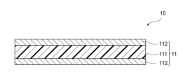
- the negative electrode 10 may be composed of the negative electrode metal layer 112, or may be composed of the negative electrode resin layer 111 and the negative electrode metal layer 112.
- the negative electrode metal layer 112 may be composed of at least one selected from the group consisting of Cu, Ni, Ti, Fe, and other metals that do not react with Li, and alloys thereof, and stainless steel (SUS).
- the "metal that does not react with Li” may be a metal that does not react with lithium ions or lithium metal to form an alloy when the secondary battery 1 is in an operating state.
- lithium metal deposits on the negative electrode includes not only lithium metal depositing on the surface of the negative electrode, but also lithium metal depositing on the surface of the solid electrolyte interface (SEI) layer or on the surface or inside of the buffer function layer.
- the buffer function layer has a solid portion (including a gel-like portion) having ionic conductivity and electrical conductivity, and a pore portion constituted by the gaps in this solid portion.
- lithium metal may precipitate on the surface of the negative electrode 10 (the interface between the negative electrode 10 and the buffer functional layer) and/or inside the buffer functional layer (the surface of the solid part of the buffer functional layer).
- the separator 20 is disposed between the negative electrode 10 and the positive electrode 30.
- the separator 20 physically and/or electrically isolates the negative electrode 10 and the positive electrode 30, and ensures ion conductivity of lithium ions.
- the separator 20 may be at least one selected from the group consisting of an insulating porous member, a polymer electrolyte, a gel electrolyte, and an inorganic solid electrolyte.
- the separator 20 may be a single member or a combination of two or more members.
- the separator 20 When the separator 20 includes an insulating porous member, the pores of the porous member are filled with a substance having ion conductivity (electrolyte, polymer electrolyte, and/or gel electrolyte, etc.). This allows the separator 20 to exhibit ion conductivity.
- a substance having ion conductivity electrolyte, polymer electrolyte, and/or gel electrolyte, etc.
- the separator 20 may be a porous polyethylene (PE) film, a porous polypropylene (PP) film, or a laminated structure thereof.
- the separator 20 may be coated on one or both sides with a separator coating layer. This may improve the cycle characteristics of the secondary battery 1.
- the separator coating layer may be a continuous film with a uniform thickness over 50% or more of the surface area of the separator 20.
- the separator coating layer may include a binder such as polyvinylidene fluoride (PVDF), a mixture of styrene butadiene rubber and carboxymethyl cellulose (SBR-CMC), and polyacrylic acid (PAA).
- the separator coating layer may be formed by adding inorganic particles such as silica, alumina, titania, zirconia, or magnesium hydroxide to the binder.
- the electrolyte may be, for example, a solution that fills a housing (not shown in FIG. 1) that houses the secondary battery 1. Also, for example, the electrolyte may be impregnated into the separator 20, or may be held in a polymer to form a polymer electrolyte or a gel electrolyte.
- the electrolyte contained in the electrolytic solution may be, for example, a lithium salt.
- the lithium salt may be, for example, one or a combination of two or more selected from the group consisting of LiI, LiCl , LiBr , LiF , LiBF4 , LiPF6 , LiAsF6 , LiSO3CF3 , LiN( SO2F ) 2 , LiN( SO2CF3 ) 2 , LiN( SO2CF3CF3 ) 2 , LiB( O2C2H4 ) 2 , LiB( C2O4 ) 2 , LiB( O2C2H4 ) F2 , LiB(OCOCF3)4, LiNO3 , and Li2SO4 .
- a chain carbonate is a carbonate that does not have a ring structure such as an aromatic ring, alicyclic ring, monocyclic ring, or heterocyclic ring.
- chain carbonate There are no particular limitations on the chain carbonate, but examples include dimethyl carbonate (DMC), diethyl carbonate, ethyl methyl carbonate (EMC), and compounds in which some or all of the hydrogen atoms in these carbonates have been replaced with fluorine.
- DMC dimethyl carbonate
- EMC ethyl methyl carbonate
- a chain ether is an ether that does not have a cyclic structure such as an aromatic ring, alicyclic ring, monocyclic ring, or heterocyclic ring.
- chain ethers include, but are not limited to, 1,1,2,2-tetrafluoroethyl-2,2,3,3-tetrafluoropropyl ether, 1,1,2,2-tetrafluoroethyl-2,2,2-trifluoroethyl ether, 1H,1H,5H-octafluoropentyl-1,1,2,2-tetrafluoroethyl ether, triethylene glycol dimethyl ether, tetraethylene glycol dimethyl ether, dimethoxyethane, diethoxyethane, dimethoxypropane, dimethoxybutane, and diethylene glycol dimethyl ether.
- solvents include, but are not limited to, acetonitrile, methyl acetate, ethyl acetate, propyl acetate, methyl propionate, ethyl propionate, 12-crown-4, trimethyl phosphate, triethyl phosphate, derivatives of 1,1,2,2-tetrafluoroethyl-2,2,3,3-tetrafluoropropyl ether, derivatives of 1,1,2,2-tetrafluoroethyl-2,2,2-trifluoroethyl ether, and derivatives of 1H,1H,5H-octafluoropentyl-1,1,2,2-tetrafluoroethyl ether.
- the total amount of the chain carbonate and cyclic carbonate relative to the total amount of the solvent is not particularly limited, but is, for example, 40% by volume or more and 100% by volume or less, 60% by volume or more and 100% by volume or less, or 80% by volume or more and 100% by volume or less.
- the amount of the chain ether contained in the total amount of the solvent is not particularly limited, but is, for example, 5% by volume or more and 40% by volume or less, and 10% by volume or more and 30% by volume or less.
- the solvent does not have to contain a chain ether.
- the amount of additive contained is not particularly limited relative to the total amount of the solvent, but is, for example, 0.1% by mass or more and 5.0% by mass or less.
- the positive electrode current collector 31 has a resin layer 311, a first metal layer 312a, and a second metal layer 312b.
- the first metal layer 312a and the second metal layer 312b are arranged so as to sandwich the resin layer 311.
- the first metal layer 312a and the second metal layer 312b are collectively referred to as the "metal layer 312."
- the metal layer 312 of the positive electrode collector 31 is in physical and/or electrical contact with the positive electrode active material layer 32 and functions to give and receive electrons to and from the positive electrode active material layer 32.
- the metal layer 312 is made of a conductor that does not react with lithium ions in a battery.
- the metal layer 312 is made of at least one material selected from the group consisting of aluminum, titanium, stainless steel, nickel, and alloys thereof.
- the metal layer 312 is aluminum or an aluminum alloy.
- the metal layer 312 is formed by vapor deposition, sputtering, electrolytic plating, or lamination of the above material on both sides of the resin layer 311.
- the thickness of each conductive layer 322 may be 0.5 ⁇ m or more and 5 ⁇ m or less, 0.7 ⁇ m or more and 3 ⁇ m or less, or 0.8 ⁇ m or more and 2.0 ⁇ m or less.
- the positive electrode active material layer 32 has a positive electrode active material.
- the positive electrode active material is a material for holding the carrier metal in the positive electrode active material layer 32, and can also be called a host material for the carrier metal.
- the positive electrode active material may be a material for holding lithium ions in the positive electrode active material layer 32, in which case lithium ions are loaded into and deloaded from the positive electrode active material by charging and discharging the battery. This can improve the stability and output voltage of the battery.
- the positive electrode active material is a metal oxide or a metal phosphate.
- the metal oxide may be, for example, a cobalt oxide-based compound, a manganese oxide-based compound, or a nickel oxide-based compound.
- the metal phosphate may be, for example, an iron phosphate-based compound or a cobalt phosphate-based compound.
- the positive electrode active material may be used alone or in combination of two or more.
- the content of the positive electrode active material in the positive electrode active material layer 32 may be 50 mass % or more and 100 mass % or less with respect to the entire positive electrode active material layer 32.
- the positive electrode active material layer 32 may contain one or more components other than the positive electrode active material.
- the positive electrode active material layer 32 may include a sacrificial positive electrode material.
- the sacrificial positive electrode material is a lithium-containing compound that undergoes an oxidation reaction and does not substantially undergo a reduction reaction in the charge/discharge potential range of the positive electrode active material.
- the positive electrode active material layer 32 may include a gel electrolyte.
- the gel electrolyte may improve the adhesive strength between the positive electrode active material layer 32 and the positive electrode current collector 31.
- the gel electrolyte includes a polymer, an organic solvent, and a lithium salt.
- the polymer in the gel electrolyte may be, for example, a copolymer of polyethylene and/or polyethylene oxide, polyvinylidene fluoride, and a copolymer of polyvinylidene fluoride and hexafluoropropylene.
- the positive electrode active material layer 32 may include a conductive additive and/or a binder.
- the conductive additive is carbon black, single-walled carbon nanotubes (SWCNT), multi-walled carbon nanotubes (MWCNT), carbon nanofibers (CF), or the like.
- the binder is polyvinylidene fluoride, polytetrafluoroethylene, styrene butadiene rubber, acrylic resin, polyimide resin, or the like.
- the content of the conductive additive is 0.5% to 30% by mass or less with respect to the entire positive electrode 34. In one embodiment, the content of the binder may be 0.5% to 30% by mass or less with respect to the entire positive electrode 34.
- the positive electrode active material layer 32 may include a polymer electrolyte.
- the polymer electrolyte is a solid polymer electrolyte that mainly contains a polymer and an electrolyte, and a semi-solid polymer electrolyte that mainly contains a polymer, an electrolyte, and a plasticizer.
- the total content of the polymer electrolyte may be 0.5% by mass to 30% by mass or less with respect to the entire positive electrode active material layer 32.
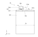
- FIG. 4A is a diagram for explaining the first metal layer 312a.
- FIG. 4A is a plan view of the positive electrode 30 as viewed from the direction of the arrow sd (the side of the first metal layer 312a) in FIG. 1 and FIG. 3.
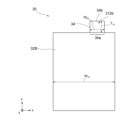
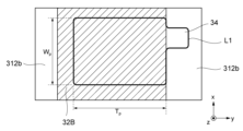
- FIG. 4B is a diagram for explaining the second metal layer 312b.
- FIG. 4B is a plan view of the positive electrode 30 as viewed from the direction of the arrow bd (the side of the second metal layer 312b) in FIG. 1 and FIG. 3.
- the first metal layer 312a has a first portion 33 where no positive electrode active material layer is provided.
- the first portion 33 has one end 33a and the other end 33b in the length direction.
- the one end 33a constitutes a boundary with the positive electrode active material layer 32A.
- the width dimension W2a of the one end 33a of the first portion 33 is larger than the width dimension W3a of the other end 33b.
- the width dimension W2a of the one end 33a may be the same as the width dimension W1a of the positive electrode active material layer 32A.
- the positive electrode active material layer 32A may have the same width dimension W1a along the length direction.
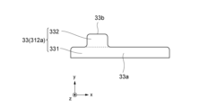
- the first portion 33 is composed of a first region 331 and a second region 332.
- the first region 331 is a region adjacent to the positive electrode active material layer 32A.
- the first region 331 is a region including one end 33a of the first portion described above.
- the first region 331 has one end 33a and the other end 331a in the longitudinal direction.
- the other end 331a has the same width dimension W2a as the one end 33a.
- the first region 331 may be rectangular.
- the second region 332 is a region adjacent to the first region 331.
- the second region 332 is a region including the other end 33b of the first portion described above.
- the second region 332 has one end 332a and the other end 33b along the longitudinal direction.
- the one end 332a may have the same width dimension W3a ( ⁇ W2a ) as the other end 33b.
- the one end 332a constitutes a part of the other end 331a of the first region 331.
- the second region 332 extends in the longitudinal direction from a part of the other end 331a of the first region 331.
- the second region 332 may be rectangular.
- the second region 332 may be various shapes (e.g., triangular, trapezoidal, etc.) other than rectangular.
- the second metal layer 312b has a second portion 34 where the positive electrode active material layer is not provided.
- the second portion 34 has one end 34a and the other end 34b in the length direction.
- the one end 34a constitutes a boundary with the positive electrode active material layer 32B.
- the one end 34a of the second portion 34 may have the same width dimension W2b as the other end 34b.
- the width dimension W2b of the one end 34a is smaller than the width dimension W1b of the positive electrode active material layer 32B.
- the positive electrode active material layer 32B may have the same width dimension W1b along the length direction.
- the second portion 34 may be rectangular.
- the second portion 34 may have various shapes (e.g., triangular, trapezoidal, etc.) other than rectangular.
- the first portion 33 and the second portion 34 have different width and length dimensions.
- the width dimension W2a of one end 33a of the first portion 33 is larger than the width dimension W2b of one end 34a of the second portion.
- the width dimension W3a of the other end 33b of the first portion is the same as the width dimension W2b of the other end 34b of the second portion.
- the length dimension T1a of the first portion (the distance from one end 33a to the other end 33b) is larger than the length dimension T1b of the second portion 34 (the distance from one end 34a to the other end 34b).
- the width dimension W1a of the positive electrode active material layer 32A and the width dimension W1b of the positive electrode active material layer 32B are the same.
- FIGS. 5A and 5B are diagrams for explaining examples of the arrangement of the positive and negative electrodes, respectively.
- FIG. 5A shows the positional relationship between the negative electrode 10 and the positive electrode 30 when viewed from the direction of the arrow sd (the surface on the side of the first metal layer 312a) in FIG. 1 and FIG. 3.
- FIG. 5B shows the positional relationship between the negative electrode 10 and the positive electrode 30 when viewed from the direction of the arrow bd (the surface on the side of the second metal layer 312b) in FIG. 1 and FIG. 3.
- the negative electrode 10 is shown by a dashed line
- the positive electrode 30 is shown by a solid line.
- the negative electrode 10 has one end 10a and the other end 10b in the length direction (y direction).
- the negative electrode 10 has a negative electrode active material layer 12 (see Figures 2A and 2D)
- the negative electrode active material layer 12 is provided between the one end 10a and the other end 10b.
- the negative electrode 10 has a constant width dimension Wn from the one end 10a to the other end 10b.
- the negative electrode end 13 extends in the length direction from the one end 10a.
- the width dimension of the negative electrode end 13 may be smaller than the width dimension Wn .
- the first region 331 of the first portion 33 completely overlaps with the negative electrode 10 in a planar view.
- the second region 332 of the first portion 33 partially overlaps with the negative electrode 10 in a planar view and partially does not overlap with the negative electrode 10 in a planar view.
- one end 33a of the first portion 33 overlaps with the negative electrode 10 in a planar view, and the other end 33b of the first portion does not overlap with the negative electrode 10 in a planar view.
- one end 10a of the negative electrode 10 is disposed between one end 33a of the first portion 33 and the other end 33b of the first portion 33 in a planar view.
- the second portion 34 partially overlaps with the negative electrode 10 in a planar view and partially does not overlap with the negative electrode 10.
- one end 34a of the second portion 34 overlaps with the negative electrode 10 in a planar view
- the other end 34b does not overlap with the negative electrode 10 in a planar view.
- one end 10a of the negative electrode 10 is disposed between one end 34a and the other end 34b of the second portion 34 in a planar view.
- the negative electrode 10 is arranged to cover the positive electrode active material layers 32A, 32B of the positive electrode 30 in a plan view. If the negative electrode 10 is not provided at a location facing the positive electrode active material layers 32A, 32B via the separator 20, metallic lithium may precipitate at that location during charging, resulting in deterioration of battery performance.
- the negative electrode 10 and the positive electrode 30 are arranged so that the distance from one end 10a of the negative electrode 10 to the positive electrode active material layer 32 in a plan view is equal to or greater than a predetermined distance (hereinafter also referred to as the "minimum separation distance").
- the distance D1 in a plan view from one end 33a of the first portion 33 to one end 10a of the negative electrode 10 may be 3 mm or less, may be 0.25 mm or more and 3 mm or less, may be 0.5 mm or more and 2.75 mm or less, or may be 0.75 mm or more and 2.5 mm or less.
- the distance D2 in a plan view from one end 34a of the second portion 34 to one end 10a of the negative electrode 10 may be 0.25 mm or more, 0.25 mm or more to 2 mm or less, 0.5 mm or more to 1.75 mm or less, or 0.75 mm or more to 1.5 mm or less.
- Distance D2 is the minimum separation distance.
- the distance D1 in a plan view from one end 33a of the first portion 33 to one end 10a of the negative electrode 10 is longer than the distance D2 in a plan view from one end 34a of the second portion 34 to one end 10a of the negative electrode 10.
- the difference between the distance D1 and the distance D2 may be 0.25 mm or more and 2.5 mm or less, 0.5 mm or more and 2 mm or less, or 0.75 mm or more and 1.75 mm or less.
- an insulating member may be further provided at a location facing the negative electrode 10 among the exposed metal surface of the positive electrode collector 31. The insulating member can suppress the above-mentioned short circuit due to damage to the separator 20 or the like.
- the first portion 33 may have a curved outer edge in part or in whole.
- the first region 331 and the second region 332 may have a rectangular shape with rounded corners (in this disclosure, "rectangular" may include an aspect in which a part of the outer edge, such as a corner, is curved).
- the first region 331 and the second region 332 of the first portion 33 may each have a shape other than a rectangular shape.
- the first region 331 may be rectangular and the second region 332 may be trapezoidal.
- the first region 331 may be rectangular or trapezoidal, and the second region 332 may be triangular or trapezoidal.
- ⁇ Secondary Battery Manufacturing Method> 7 is a flowchart showing an example of a method for manufacturing the secondary battery 1.
- This method includes a step ST1 of preparing a positive electrode material, a step ST2 of forming a positive electrode 30, a step ST3 of forming a negative electrode 10, and a step ST4 of sealing the positive electrode 30, the negative electrode 10, the separator 20, and, if necessary, an electrolyte solution in a sealed container.
- the positive electrode active material layer 32 is formed on both sides of the positive electrode current collector 31, a deviation of the formation surface in the length direction may occur due to, for example, the accuracy of the coating device.
- the positive electrode active material layer 32B on the second metal layer 312b is formed with a deviation of T dp toward the side where the positive electrode end 35 is formed compared to the positive electrode active material layer 32A on the first metal layer 312a.
- the positive electrode material is cut out at the cutout line L1 shown in FIG. 8A and FIG. 8C.
- the cutout line L1 is set to match the coating area of the positive electrode active material layer 32B shown in FIG. 8A.
- the first metal layer 312a is formed with a first portion 33 composed of a first region 331 and a second region 332 (FIG. 8C).
- the second metal layer 312b is formed with a second portion 34.
- FIG. 9A and 9B are diagrams for explaining other examples of cutting out the positive electrode material.
- FIG. 9A and FIG. 9B are examples of the case where the positive electrode material is cut out along the cutout line L2 when the coating surface shown in FIG. 8B is misaligned.
- the cutout line L2 is set to match the coating area of the positive electrode active material layer 32A shown in FIG. 9B.
- the positive electrode active material layer 32B on the second metal layer 312b after being cut out along the cutout line L2 has a rectangular area 32B1 with a width Wp and a length Tq , and a rectangular area 32B2 with the same width and length Tdp as the positive electrode end 35B.
- a sheet (thickness in lamination direction: 15 ⁇ m, size in width direction and length direction: 45 mm ⁇ 45 mm) whose surface was coated with a mixture of polyvinylidene fluoride (PVDF) and Al 2 O 3 was prepared as the separator 20 .
- PVDF polyvinylidene fluoride
- the positive electrode 30 was prepared. Specifically, first, a 6 ⁇ m-thick film-like polyethylene terephthalate (PET) film with 1.0 ⁇ m of Al deposited on both sides was prepared as the positive electrode current collector 31. Next, a mixed material was prepared by mixing 96 parts by mass of LiNi 0.8 Co 0.15 Al 0.05 O 2 as the positive electrode active material, 2 parts by mass of carbon black as a conductive assistant, and 2 parts by mass of polyvinylidene fluoride (PVDF) as a binder in N-methyl-pyrrolidone (NMP) as a solvent.
- PVDF polyvinylidene fluoride
- this mixed material was applied to both sides of the positive electrode current collector so that the basis weight was 23 mg/cm 2 , and pressed to form the positive electrode active material layer 32. Thereafter, in the case of cut-out line L1 in FIG. 10 (FIGS. 10C and 10D), the positive electrode current collector 31 on which the positive electrode active material layer 32 was formed was cut out so that Tp was 40 mm, Tq was 39 mm, Wp was 40 mm, and Tdp was 1 mm.
- the separator 20, the positive electrode 30, and the negative electrode 10 were arranged so that the positive electrode 30 and the negative electrode 10 faced each other through the separator 20 to form a laminate.
- 10 positive electrodes 30 were laminated, and both ends of the laminate in the lamination direction were negative electrodes 10.
- the negative electrodes 10 at both ends were provided with a negative electrode active material layer 12 only on the surface facing the positive electrode 30 through the separator 20, and the negative electrodes 10 other than the both ends were provided with a negative electrode active material layer 12 on both sides.
- the positive electrode 30 and the negative electrode 10 were arranged so that D1 was 2 mm and D2 was 1 mm in FIG. 10(C) and FIG. 10(D).
- the electrolyte used was prepared by dissolving lithium hexafluorophosphate (LiPF 6 ) in a solvent containing a 30:35:35 mixture of ethylene carbonate (EC), dimethyl carbonate (DMC), and ethyl methyl carbonate (EMC) in a ratio of 30:35:35 parts by mass to make a 1 M electrolyte solution to which 2 parts by mass of vinylene carbonate (VC) was added.
- LiPF 6 lithium hexafluorophosphate
- EC ethylene carbonate
- DMC dimethyl carbonate
- EMC ethyl methyl carbonate
- Secondary batteries 1 of Examples 2 to 4 were fabricated in the same manner as in Example 1, except that the type of positive electrode current collector, the type of negative electrode current collector, and the shape of the positive electrode were changed based on Figures 10 and 11.
- the lithium secondary batteries of Comparative Examples 1 to 5 were fabricated in the same manner as in Example 1, except that the type of positive electrode current collector, the type of negative electrode current collector, and the shape of the positive electrode were changed based on Figures 10 and 11.
- the Cu-deposited resin film is a 6 ⁇ m-thick polyethylene terephthalate (PET) film with 1.0 ⁇ m of Cu deposited on both sides.
- PET polyethylene terephthalate
- the Al foil is 8 ⁇ m thick.
- the lithium secondary batteries of each Example and Comparative Example were CC-charged at a current of 0.1 C in an environment at a temperature of 25° C. until the voltage reached 4.2 V, and then CC-discharged at a current of 0.1 C until the voltage reached 3.0 V.
- the lithium secondary batteries of each Example and Comparative Example were CC-charged at a current of 0.3 C until the voltage reached 4.2 V, and then CC-discharged at a current of 0.3 C until the voltage reached 3.0 V (first cycle). This cycle was repeated 100 times.
- FIG. 10 is a diagram showing the configurations and results of the examples and comparative examples. It was found that the lithium secondary batteries of the examples did not ignite, had a large cell capacity, and had a high capacity retention rate. On the other hand, it was found that the lithium secondary batteries of Comparative Examples 1 to 3 had a high capacity retention rate, but ignited and had a small cell capacity. It was also found that the lithium secondary battery of Comparative Example 4 did not ignite, had a large cell capacity, but had a low capacity retention rate. It was also found that the lithium secondary battery of Comparative Example 5 had a large cell capacity and a high capacity retention rate, but ignited. That is, it was found that the lithium secondary batteries of Examples 1 to 4 had good cycle characteristics in addition to high safety and good cell capacity.
- the lithium secondary batteries of Comparative Examples 1 to 3 were found to have good cycle characteristics, but low safety and relatively small cell capacity.
- the reasons for the low safety are not particularly limited, but are thought to be as follows. It is presumed that abnormal heat generation occurred when the positive electrode and negative electrode were short-circuited because a positive electrode collector consisting of only a metal layer was used, rather than a positive electrode collector consisting of a resin layer sandwiched between metal layers.
- the reasons for the low cell capacity are not particularly limited, but are thought to be due to the small surface area of the positive electrode active material layer.
- the lithium secondary battery of Comparative Example 5 was found to have good cell capacity and good cycle characteristics, but low safety.
- the reasons for this are not particularly limited, but are thought to be as follows. It is speculated that abnormal heat generation occurred when a short circuit occurred between the positive electrode collector and the negative electrode active material layer because a positive electrode collector consisting of only a metal layer was used, rather than a positive electrode collector consisting of a resin layer sandwiched between metal layers.
- the first portion has one end and the other end in the longitudinal direction, the one end of the first portion overlaps with the negative electrode in a plan view, and the other end of the first portion does not overlap with the negative electrode in a plan view;
- the second portion has one end and the other end in the longitudinal direction, the one end of the second portion overlaps with the negative electrode in a planar view, and the other end of the second portion does not overlap with the negative electrode in a planar view.
- (Appendix 7) The lithium secondary battery of claim 1, wherein the first portion comprises a first rectangular region having a first width dimension and a second rectangular region having a second width dimension smaller than the first width dimension.
- the first portion has one end and the other end in the longitudinal direction
- the second portion has one end and the other end in the longitudinal direction
- the negative electrode has one end and the other end in the longitudinal direction
- a distance from the one end of the first portion to the one end of the negative electrode in a plan view is longer than a distance from the one end of the second portion to the one end of the negative electrode in a plan view.
- (Appendix 18) 18. The lithium secondary battery according to claim 1, wherein the negative electrode comprises a negative electrode current collector formed by sandwiching a resin layer between a pair of metal layers.
Landscapes
- Chemical & Material Sciences (AREA)
- Engineering & Computer Science (AREA)
- Chemical Kinetics & Catalysis (AREA)
- Electrochemistry (AREA)
- General Chemical & Material Sciences (AREA)
- Materials Engineering (AREA)
- Manufacturing & Machinery (AREA)
- Battery Electrode And Active Subsutance (AREA)
- Cell Electrode Carriers And Collectors (AREA)
- Secondary Cells (AREA)
Priority Applications (2)
| Application Number | Priority Date | Filing Date | Title |
|---|---|---|---|
| PCT/JP2023/044741 WO2025126407A1 (ja) | 2023-12-13 | 2023-12-13 | リチウム2次電池及びリチウム2次電池の製造方法 |
| JP2024523282A JP7573925B1 (ja) | 2023-12-13 | 2023-12-13 | リチウム2次電池及びリチウム2次電池の製造方法 |
Applications Claiming Priority (1)
| Application Number | Priority Date | Filing Date | Title |
|---|---|---|---|
| PCT/JP2023/044741 WO2025126407A1 (ja) | 2023-12-13 | 2023-12-13 | リチウム2次電池及びリチウム2次電池の製造方法 |
Publications (1)
| Publication Number | Publication Date |
|---|---|
| WO2025126407A1 true WO2025126407A1 (ja) | 2025-06-19 |
Family
ID=93254473
Family Applications (1)
| Application Number | Title | Priority Date | Filing Date |
|---|---|---|---|
| PCT/JP2023/044741 Pending WO2025126407A1 (ja) | 2023-12-13 | 2023-12-13 | リチウム2次電池及びリチウム2次電池の製造方法 |
Country Status (2)
| Country | Link |
|---|---|
| JP (1) | JP7573925B1 (https=) |
| WO (1) | WO2025126407A1 (https=) |
Cited By (1)
| Publication number | Priority date | Publication date | Assignee | Title |
|---|---|---|---|---|
| JP7820604B1 (ja) * | 2025-10-02 | 2026-02-25 | 慎司 松田 | 全固体電池及びその製造方法 |
Citations (6)
| Publication number | Priority date | Publication date | Assignee | Title |
|---|---|---|---|---|
| JPH09283149A (ja) * | 1996-04-10 | 1997-10-31 | Japan Storage Battery Co Ltd | 電池用極板の集電体及びその集電体を用いた電池 |
| JPH11102711A (ja) * | 1997-09-25 | 1999-04-13 | Denso Corp | リチウムイオン二次電池 |
| JP2006139919A (ja) * | 2004-11-10 | 2006-06-01 | Ngk Spark Plug Co Ltd | リチウムイオン二次電池およびその製造方法 |
| WO2009157263A1 (ja) * | 2008-06-23 | 2009-12-30 | シャープ株式会社 | リチウムイオン二次電池 |
| JP2014102897A (ja) * | 2012-11-16 | 2014-06-05 | Toyota Industries Corp | 蓄電装置及び蓄電装置の製造方法 |
| JP2021022481A (ja) * | 2019-07-26 | 2021-02-18 | 株式会社豊田自動織機 | 電極組立体 |
-
2023
- 2023-12-13 JP JP2024523282A patent/JP7573925B1/ja active Active
- 2023-12-13 WO PCT/JP2023/044741 patent/WO2025126407A1/ja active Pending
Patent Citations (6)
| Publication number | Priority date | Publication date | Assignee | Title |
|---|---|---|---|---|
| JPH09283149A (ja) * | 1996-04-10 | 1997-10-31 | Japan Storage Battery Co Ltd | 電池用極板の集電体及びその集電体を用いた電池 |
| JPH11102711A (ja) * | 1997-09-25 | 1999-04-13 | Denso Corp | リチウムイオン二次電池 |
| JP2006139919A (ja) * | 2004-11-10 | 2006-06-01 | Ngk Spark Plug Co Ltd | リチウムイオン二次電池およびその製造方法 |
| WO2009157263A1 (ja) * | 2008-06-23 | 2009-12-30 | シャープ株式会社 | リチウムイオン二次電池 |
| JP2014102897A (ja) * | 2012-11-16 | 2014-06-05 | Toyota Industries Corp | 蓄電装置及び蓄電装置の製造方法 |
| JP2021022481A (ja) * | 2019-07-26 | 2021-02-18 | 株式会社豊田自動織機 | 電極組立体 |
Cited By (1)
| Publication number | Priority date | Publication date | Assignee | Title |
|---|---|---|---|---|
| JP7820604B1 (ja) * | 2025-10-02 | 2026-02-25 | 慎司 松田 | 全固体電池及びその製造方法 |
Also Published As
| Publication number | Publication date |
|---|---|
| JPWO2025126407A1 (https=) | 2025-06-19 |
| JP7573925B1 (ja) | 2024-10-28 |
Similar Documents
| Publication | Publication Date | Title |
|---|---|---|
| CN102812589B (zh) | 非水电解液二次电池 | |
| CN102148357B (zh) | 用于锂离子二次电池的负极、锂离子二次电池、电力工具、电动车辆、和电力存储系统 | |
| CN112447941B (zh) | 非水电解质二次电池 | |
| WO2018154989A1 (ja) | 二次電池およびその製造方法 | |
| US20250239622A1 (en) | Lithium secondary battery and method for manufacturing same | |
| US12548759B2 (en) | Battery and method for producing same | |
| US20200388874A1 (en) | Planar, thin-film electrochemical device and method of making the same | |
| JP7573925B1 (ja) | リチウム2次電池及びリチウム2次電池の製造方法 | |
| WO2022191297A1 (ja) | 負極用材料、負極、リチウム二次電池、及び、負極用材料の製造方法 | |
| JP2013206724A (ja) | 非水電解質二次電池 | |
| JP2020149920A (ja) | リチウム二次電池 | |
| JP2023034053A (ja) | パウチ型非水電解質二次電池 | |
| JP7492797B1 (ja) | リチウム2次電池 | |
| JP7752450B2 (ja) | リチウム2次電池 | |
| JP2022062976A (ja) | 非水電解質二次電池 | |
| US20260081208A1 (en) | Lithium secondary battery | |
| US20260011791A1 (en) | Lithium secondary battery | |
| US20240154177A1 (en) | Lithium secondary battery | |
| US20230268589A1 (en) | Inflatable pouch designs for electrochemical cells and methods of forming the same | |
| JP2020077575A (ja) | リチウムイオン二次電池 | |
| WO2025243430A1 (ja) | リチウム2次電池、バッテリアセンブリ及び電動車 | |
| WO2025220215A1 (ja) | 2次電池 | |
| WO2025229751A1 (ja) | リチウム2次電池 | |
| WO2025126484A1 (ja) | リチウム2次電池 | |
| WO2025141819A1 (ja) | リチウム2次電池 |
Legal Events
| Date | Code | Title | Description |
|---|---|---|---|
| ENP | Entry into the national phase |
Ref document number: 2024523282 Country of ref document: JP Kind code of ref document: A |
|
| WWE | Wipo information: entry into national phase |
Ref document number: 2024523282 Country of ref document: JP |
|
| 121 | Ep: the epo has been informed by wipo that ep was designated in this application |
Ref document number: 23961473 Country of ref document: EP Kind code of ref document: A1 |