WO2025126281A1 - 把持装置 - Google Patents
把持装置 Download PDFInfo
- Publication number
- WO2025126281A1 WO2025126281A1 PCT/JP2023/044287 JP2023044287W WO2025126281A1 WO 2025126281 A1 WO2025126281 A1 WO 2025126281A1 JP 2023044287 W JP2023044287 W JP 2023044287W WO 2025126281 A1 WO2025126281 A1 WO 2025126281A1
- Authority
- WO
- WIPO (PCT)
- Prior art keywords
- pair
- gripping device
- finger
- portions
- finger portions
- Prior art date
- Legal status (The legal status is an assumption and is not a legal conclusion. Google has not performed a legal analysis and makes no representation as to the accuracy of the status listed.)
- Pending
Links
Images






Classifications
-
- B—PERFORMING OPERATIONS; TRANSPORTING
- B25—HAND TOOLS; PORTABLE POWER-DRIVEN TOOLS; MANIPULATORS
- B25J—MANIPULATORS; CHAMBERS PROVIDED WITH MANIPULATION DEVICES
- B25J15/00—Gripping heads and other end effectors
- B25J15/08—Gripping heads and other end effectors having finger members
Definitions
- the present disclosure relates to a gripping device for gripping an object.
- a grasping device called a robot hand or gripper is used.
- Patent Document 1 discloses a robot hand equipped with a first cylinder that controls the opening and closing of the fingers, and a sub-cylinder built into the first cylinder. The maximum opening amount of the robot hand changes when the sub-cylinder disclosed in Patent Document 1 receives a supply of air.
- Patent Document 2 discloses a robot hand equipped with a finger unit that can be attached to and detached from the hand body.
- the robot hand disclosed in Patent Document 2 has multiple finger units with different shapes in order to grasp objects of various shapes.
- Patent Document 1 requires a sub-cylinder to change the maximum opening amount. This results in the robot hand becoming larger.
- the objective of this disclosure is to provide a gripping device that is compact and low-cost, and can grip objects of various shapes.
- the gripping device disclosed herein comprises a pair of finger sections for gripping an object, a drive section for moving the pair of finger sections in an opening/closing direction relative to the object, and a position adjustment means for adjusting the mounting position of the pair of finger sections relative to the drive section, each of the pair of finger sections having the same shape, and the distance between the tips of the pair of finger sections can be changed by the position adjustment means.
- the gripping device disclosed herein is compact and low-cost, and can grip objects of various shapes.
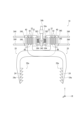
- FIG. 1 is a diagram showing an example of the configuration of a gripping device 10 according to the first embodiment.
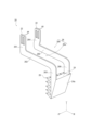
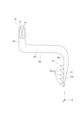
- FIG. 2A is a perspective view of a finger portion 20 included in the gripping device 10 according to the first embodiment.
- FIG. 2B is a front view of the finger portion 20 included in the gripping device 10 according to the first embodiment.
- FIG. 2C is a right side view of the finger portion 20 included in the gripping device 10 according to the first embodiment.
- FIG. 3A is a perspective view of the gripping device 10 according to the first embodiment.
- FIG. 3B is a right side view of the gripping device 10 according to the first embodiment.
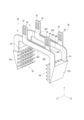
- FIG. 4A is a perspective view of the drive unit 30 included in the gripping device 10 according to the first embodiment.
- FIG. 4B is a plan view of the drive unit 30 included in the gripping device 10 according to the first embodiment.
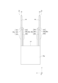
- FIG. 5 is a schematic cross-sectional view illustrating the operation of the actuator 36 included in the gripping device 10 according to the first embodiment.
- FIG. 6A is a diagram showing a first attachment position of the attachment portion 32 with respect to the finger portion 20 included in the gripping device 10 according to the first embodiment.
- FIG. 6B is a diagram showing a second attachment position of the attachment portion 32 with respect to the finger portion 20 included in the gripping device 10 according to the first embodiment.
- FIG. 6C is a diagram showing a third attachment position of the attachment portion 32 with respect to the finger portion 20 included in the gripping device 10 according to the first embodiment.
- FIG. 6D is a diagram showing a fourth attachment position of the attachment portion 32 with respect to the finger portion 20 included in the gripping device 10 according to the first embodiment.
- FIG. 7 is a diagram showing a configuration example of a gripping device 15 according to Modification 1 of the first embodiment.
- FIG. 8 is a perspective view of a finger portion 20 provided on a gripping device 15 according to a first modified example of the first embodiment.
- Parallel, right-angled, orthogonal, horizontal, and vertical may include approximately parallel, approximately right-angled, approximately orthogonal, approximately horizontal, and approximately vertical, respectively.
- the drawings have a virtual three-dimensional coordinate system (XYZ Cartesian coordinate system) consisting of mutually orthogonal X-, Y-, and Z-axes (XYZ axes) set up.
- XYZ Cartesian coordinate system XYZ Cartesian coordinate system
- a black circle in a circle on the coordinate axis indicates that the front side of the paper is the positive area of the coordinate axis.
- a cross in a circle on the coordinate axis indicates that the front side of the paper is the negative area of the coordinate axis.
- this coordinate system is defined for the purpose of explanation and does not limit the posture of the gripping device etc. related to this embodiment.
- the X-axis direction is the direction in which each finger portion (for example, finger portion 20 in the case of FIG. 1) moves.
- the Y-axis direction is the direction in which each finger portion extends.
- the Z-axis is the direction perpendicular to the X-axis and Y-axis.
- the X-axis direction is an example of the first direction
- the Y-axis direction is an example of the second direction
- the Z-axis direction is an example of the third direction.
- a view of an object viewed from the +Z side in the opposite direction to the Z axis along the Z axis direction is called a front view.
- a view of an object viewed from the -X side in the X axis direction along the X axis direction is called a left side view
- a view of an object viewed from the +X side in the opposite direction to the X axis is called a right side view.
- a view of an object viewed from the +Y side in the opposite direction to the Y axis along the Y axis direction is called a top view
- a view of an object viewed from the -Y side in the Y axis direction is called a bottom view.
- the X-axis direction may be referred to as the left-right direction (the opening and closing direction of the finger portion 20), the Y-axis direction as the up-down direction, and the Z-axis direction as the front-to-back direction.
- the +X side may be referred to as the right side, the -X side as the left side, the +Y side as the top side, the -Y side as the bottom side, the +Z side as the front side, and the -Z side as the back side.
- the inner side in the X-axis direction may refer to the side approaching an imaginary Y-Z plane that divides the gripping device in half in the X-axis direction
- the outer side in the X-axis direction may refer to the side away from the imaginary Y-Z plane
- the inner side in the Z-axis direction may refer to the side approaching an imaginary X-Y plane that divides the gripping device in half in the Z-axis direction
- the outer side in the Z-axis direction may refer to the side away from the imaginary X-Y plane.
- some reference numerals may be omitted in order to make the drawing easier to understand.
- FIG. 1 is a diagram showing an example of the configuration of a gripping device 10 according to the first embodiment.
- the gripping device 10 grips the object W by moving each of the pair of finger units 20 toward or away from each other along the X-axis direction (the opening and closing direction of the finger units 20).
- the gripping device 10 attached to a robot installed in a food service factory, a cafeteria, a restaurant, etc. will be described.
- the robot automates food distribution and arranges tableware (object W) on which food is served on a tray T.
- FIG. 1 is a diagram showing an example of the configuration of a gripping device 10 according to the first embodiment.
- the gripping device 10 grips the object W by moving each of the pair of finger units 20 toward or away from each other along the X-axis direction (the opening and closing direction of the finger units 20).
- the gripping device 10 attached to a robot installed in a food service factory, a cafeteria, a restaurant, etc. will be described.
- Tableware generally refers to containers used for eating, and includes, for example, plates, bowls, cups, and glasses.
- object W is not particularly limited and may be, for example, various devices, parts, food, etc., and may have various shapes, masses, and sizes (for example, rod-shaped, plate-shaped, or spherical).
- the gripping device 10 includes a pair of finger units 20 that grip the object W, a drive unit 30 that moves the pair of finger units 20 in an opening/closing direction relative to the object W, and a position adjustment means 40 that adjusts the mounting position of the pair of finger units 20 relative to the drive unit 30.
- the gripping device 10 grips or releases the object W by changing the distance between the tips of the finger units 20 using the drive unit 30.
- the attachment position of each finger section 20 relative to the drive section 30 is adjusted to change the spacing between the finger sections 20 when the gripping device 10 is fully opened and closed.
- Fig. 2A is a perspective view of the finger unit 20 included in the gripping device 10 according to the first embodiment.
- Fig. 2B is a front view of the finger unit 20 included in the gripping device 10 according to the first embodiment.
- Fig. 2C is a right side view of the finger unit 20 included in the gripping device 10 according to the first embodiment. Since each of the finger units 20 has the same shape, Figs. 2A to 2C show only one of the finger units 20.
- the finger portion 20 has a pair of base ends 22 provided at the base end of the finger portion 20 and attached to the drive portion 30, a contact portion 24 provided at the tip of the finger portion 20 and contacting the object W when the object W is gripped, a pair of intermediate portions 26 (a first intermediate portion 26a and a second intermediate portion 26b described below) connecting the base ends 22 and the contact portions 24, and a rubber pad 28 attached to the contact surface of the contact portion 24 with the object W.
- the finger portion 20 is also integrally formed from a resin material.
- the base end portion 22 is in the shape of a substantially rectangular plate, and is provided with a hole 44 serving as a position adjustment means 40 .
- the first intermediate portion 26a has a first connection portion 261 that is arranged to hang down downward (-Y side) from the base end portion 22, a second connection portion 262 that is arranged to extend to the right side (+X side) from the first connection portion 261, and a third connection portion 263 that is arranged to hang down downward (-Y side) from the second connection portion 262.
- the second intermediate portion 26b has a step portion 264 formed by protruding from the base end portion 22 toward the first intermediate portion 26a (+Z side, inward in the Z-axis direction), a first connection portion 265 provided by extending from the step portion 264 to the right side (+X side), and a second connection portion 266 provided by hanging down from the first connection portion 265 to the lower side (-Y side).
- FIG. 3A is a perspective view of the gripping device 10 according to the first embodiment.
- FIG. 3B is a right side view of the gripping device 10 according to the first embodiment.
- the drive unit 30 and the position adjustment means 40 are omitted in FIGS. 3A and 3B.
- some reference numerals have been omitted and some structures have been exaggerated.
- each of the finger portions 20 has the same shape, it is easy to attach them to the drive unit 30, and the cost of the gripping device 10, including the manufacturing cost, can be reduced. Furthermore, since the finger portions 20 are made of a resin material, the weight of the gripping device 10 can be reduced.
- the contact portion 24 is a substantially rectangular plate having an inclined portion 24a whose thickness in the X-axis direction decreases toward the lower side (-Y side). For example, when tableware is lined up along the X-axis direction, the inclined portion 24a can prevent the tableware adjacent to the object to be grasped W from coming into contact with the finger portion 20.
- the pad 28 has an uneven surface formed on the surface on the inside in the X-axis direction.
- an uneven surface a case where a plurality of upward protrusions 28a are formed on the surface of the pad 28 is shown.
- the protrusions 28a are arranged in a lattice pattern at regular intervals on the surface of the pad 28.
- the protrusions 28a are made of flexible rubber, urethane foam, or the like.
- the protrusions 28a support the grasped object W facing upward, thereby preventing the object W from falling.
- FIG. 4A is a perspective view of the drive unit 30 included in the gripping device 10 according to the first embodiment.
- Fig. 4B is a plan view of the drive unit 30 included in the gripping device 10 according to the first embodiment.
- the drive unit 30 has a pair of mounting portions 32 to which the finger portion 20 is attached, a guide mechanism 34 that supports the pair of mounting portions 32 so that they can move in the X-axis direction, and an actuator 36 that moves the pair of mounting portions 32.
- the mounting portions 32 are hollow and generally rectangular with an opening, and are integrally formed from, for example, resin. Each of the mounting portions 32 has the same shape.
- the mounting portions 32 include two mounting surfaces 32a and a fixing surface 32b.
- the mounting surfaces 32a are disposed opposite each other in the Z-axis direction, and are surfaces to which the finger portions 20 are attached.
- the fixing surface 32b is an outer end surface of the mounting portions 32 in the X-axis direction, which is formed continuously to connect the two mounting surfaces 32a.
- One end of the actuator 36 is fixed to the fixing surface 32b by a fixing means such as an adhesive.
- the mounting portion 32 also has through holes 321, which are provided at the four corners of the fixing surface 32b and through which the linear shaft 344 passes.
- a linear bushing 345 is fitted into the through hole 321. Therefore, the mounting portion 32 is movably supported by the linear shaft 344.
- the guide mechanism 34 has a base portion 34a, a support portion 34b, and a guide portion 34c.
- the base portion 34a is a rectangular plate-shaped housing formed of, for example, resin and having a space inside.
- the base portion 34a has four fixing holes 341 through which the linear shaft 344 is fixed at its four corners.
- the base portion 34a also has three openings (a first opening 342 and a pair of second openings 343).
- a hose connected to a pressure source P (a compressor for gas or liquid) is inserted into the first opening 342 provided at the front (+Z side) end of the base portion 34a and the second opening 343 provided at the outer end of the base portion 34a in the X-axis direction, and is connected to the actuator 36. That is, compressed fluid can be supplied from the pressure source P to the pair of actuators 36 through the first opening 342 of the base portion 34a, so that space for piping can be saved.
- the method of connecting the hose and the actuator 36 is not particularly limited.
- the actuator 36 and the pressure source P may be connected by attaching a pipe joint to the opening 342 and connecting the hose to the pipe joint.
- the support pillar 34b is erected on the upper (+Y) side of the base 34a and is supported by the robot arm via a connection means such as a flange.
- the support pillar 34b is made of, for example, resin.
- the guide portion 34c is made of a general-purpose part made of resin, for example, and has four linear shafts 344 and linear bushings 345. As described above, the guide portion 34c supports the mounting portion 32 so that it can move linearly in the X-axis direction.
- Actuator 36 A pair of actuators 36 are provided between the base portion 34a and the attachment portion 32.
- the gripping device 10 uses a plurality of lightweight and flexible soft actuators as fluid pressure actuators.
- the gripping device 10 grips the object W by utilizing the expansion and contraction of the soft actuators.
- soft actuators are preferable, other fluid pressure actuators, electric actuators, etc. may also be used.
- FIG. 5 is a schematic cross-sectional view illustrating the expansion and contraction of the actuator 36 provided in the gripping device 10 according to the first embodiment.
- the solid line indicates the actuator 36 when no pressure is applied
- the two-dot chain line indicates the actuator 36 expanded when pressure is applied.
- FIG. 5 is a cross-sectional view taken along the radial direction of the actuator 36. Also, since each of the actuators 36 has the same shape, FIG. 5 shows only one of the actuators 36. Also, to make the figure easier to understand, some reference numerals have been omitted and some structures have been exaggerated.
- the actuator 36 when the actuator 36 is pressurized, the actuator 36 expands along the X-axis direction, moving the mounting portion 32 away from the base portion 34a.
- the actuator 36 when the actuator 36 is not pressurized (including when fluid flows out of the actuator 36), the actuator 36 contracts along the X-axis direction, moving the mounting portion 32 closer to the base portion 34a.
- the actuator 36 has an actuator body portion 36a and a sealing portion 36c.
- the actuator body 36 a is composed of a tube 361 and a compression spring 363 .
- the tube 361 When pressurized, the original tube contracts in the X-axis direction and expands in the radial direction.
- the tube 361 according to this embodiment can extend in the X-axis direction when pressurized by suppressing radial expansion by wrapping a compression spring 363 around the outside of the tube 361.
- the tube 361 shrinks inward in the X-axis direction.
- the tube 361 is preferably made of an elastic material such as silicone rubber, but may be made of other materials.
- the tube 361 also has a spring retaining portion 362 on its surface.
- the spring retaining portion 362 has an uneven shape formed on the surface of the tube 361, and is designed to catch the pitch of the compression spring 363. When the tube 361 expands or contracts, the compression spring 363 is caught in the uneven shape, which prevents the compression spring 363 from falling off the tube 361.
- the sealing portion 36c has a first sealing portion 364 provided on the base portion 34a side and a second sealing portion 366 provided on the mounting portion 32 side.
- the first sealing portion 364 has a connection port 365 into which a hose is inserted, and functions to seal between the actuator body portion 36a and the base portion 34a.
- the first sealing portion 364 is also fixed to the base portion 34a by a fixing means such as an adhesive.
- the second sealing portion 366 functions to seal between the actuator body portion 36a and the mounting portion 32.
- the second sealing portion 366 is also fixed to the fixing surface 32b by a fixing means such as an adhesive.
- the sealing portion 36c may be of any type as long as it has the function of sealing between the actuator body portion 36a and the base portion 34a, and between the actuator body portion 36a and the mounting portion 32.
- the drive unit 30 has mounting parts 32 each having the same shape, the actuators 36 each having the same shape, and the guide mechanism 34 is constructed from general-purpose parts, so that the cost of the gripping device 10, including the manufacturing cost, can be reduced. Furthermore, most of the drive unit 30 (mounting parts 32, guide mechanism 34, etc.) is made of a resin material, so that the weight of the gripping device 10 can be reduced.
- Fig. 6A is a diagram showing a first mounting position of the gripping device 10 according to the first embodiment.
- Fig. 6B is a diagram showing a second mounting position of the gripping device 10 according to the first embodiment.
- Fig. 6C is a diagram showing a third mounting position of the gripping device 10 according to the first embodiment.
- Fig. 6D is a diagram showing a fourth mounting position of the gripping device 10 according to the first embodiment.
- the position adjustment means 40 has five convex portions 42 formed on the mounting portion 32 and two holes 44 that fit with the convex portions 42 provided on the base end portion 22 of the finger portion 20.
- the convex portions 42 and the holes 44 can be fitted with each other.
- the finger portion 20 is detachably attached to the mounting portion 32 by fitting the convex portions 42 with the holes 44.
- the mounting position of the finger portion 20 with respect to the mounting portion 32 can be adjusted by changing the combination of fitting between some of the multiple convex portions 42 (two of the five convex portions 42) and the two holes 44.
- the holes 44 are two substantially rectangular holes that penetrate the base end portion 22 in the Z-axis direction.
- the protrusions 42 are generally rectangular projections that protrude outward in the Z-axis direction from the mounting surface 32a. Five protrusions 42 are formed at intervals in the X-axis direction. The intervals between the contact portions 24 when fully open and when fully closed can be adjusted by changing the combination of the protrusions 42 and holes 44 that fit together.
- the number of holes 44 is two or more, it may be one.
- the number of protrusions 42 may be any number greater than the number of holes 44.
- the shapes of the protrusions 42 and holes 44 are not particularly limited and may be modified as appropriate.
- the number of pairs of fitting protrusions 42 and holes 44 may be two or more, and the size and shape of one set of protrusions 42 and holes 44 may be the same as or different from the size and shape of another set of protrusions 42 and holes 44.
- an engagement protrusion 44a that engages with the convex portion 42 may be provided in the hole portion 44, and a recess 42a that engages with the engagement protrusion 44a may be provided in the convex portion 42, and the hole portion 44 may be pushed downward (to the -Y side) to engage the engagement protrusion 44a with the recess 42a, thereby locking the finger portion 20 to the attachment portion 32.
- the spacing of the contact portions 24 when fully open and closed is narrowest when the combination of the convex portion 42 and the hole portion 44 is fitted as shown in FIG. 6A, and widest when the combination of the convex portion 42 and the hole portion 44 is fitted as shown in FIG. 6D. That is, the further outward in the X-axis direction the position of the convex portion 42 that fits with the hole portion 44, the narrower the spacing of the contact portions 24 when fully open and closed. The further inward in the X-axis direction the position of the convex portion 42 that fits with the hole portion 44, the wider the spacing of the contact portions 24 when fully open and closed.
- the fitting combination of the convex portion 42 and the hole portion 44 is, the narrower the spacing of the contact portions 24 when fully open and closed.
- the further inward in the X-axis direction the fitting combination of the convex portion 42 and the hole portion 44 is, the wider the spacing of the contact portions 24 when fully open and closed.
- the convex portion 42 that fits into the hole portion 44 can be changed to the convex portion 42 on the outside in the X-axis direction to grip the object W.
- the interval between the contact portions 24 when fully open and closed to match the shape of the object W
- multiple types of finger portions 20 that match the shape of the object W are not required and one type of finger portion 20 can handle objects W of various shapes, it is possible to reduce the cost of the gripping device 10, including the manufacturing cost.
- the distance D1 of the contact portions 24 when fully open and the distance D2 of the contact portions 24 when closed are determined based on the diameter of tableware used in food service factories and the like. Specifically, they are as follows. In the gripping device 10 shown in FIG. 6A, D1 is about 126 mm, and D2 is about 56 mm. In the gripping device 10 shown in FIG. 6B, D1 is about 142 mm, and D2 is about 72 mm. In the gripping device 10 shown in FIG. 6C, D1 is about 158 mm, and D2 is about 88 mm. In the gripping device 10 shown in FIG. 6D, D1 is about 174 mm, and D2 is about 104 mm. Note that the above D1 and D2 are merely examples and are not particularly limited, and may be changed as appropriate depending on the use and shape of the target object W.
- each of the pair of finger portions 20 has the same shape, and the distance between the tips of the pair of finger portions 20 can be changed by the position adjustment means 40, so that there is no need to provide a separate drive means for changing the distance between the tips of the pair of finger portions 20, making it possible to miniaturize the gripping device 10 and to grip objects W of various shapes.
- the gripping device 10 does not require multiple types of finger portions 20 to match the shapes of the object W, and one type of finger portion 20 can handle objects W of various shapes, so that the costs of the gripping device 10, including the manufacturing costs, can be reduced.
- the position adjustment means 40 has a convex portion 42 formed on the drive unit 30 and a hole portion 44 provided on each of the pair of finger portions 20 that fits into the convex portion 42, and each of the pair of finger portions 20 is detachably attached to the drive unit 30 by fitting the convex portion 42 into the hole portion 44.
- a pad 28 having an upward protrusion 28a is attached to the surface of the contact portion 24 that comes into contact with the object W, so that the protrusion 28a supports the gripped object W facing upward, preventing the object W from falling.
- Fig. 7 is a diagram showing a configuration example of the gripping device 15 according to Modification 1 of the first embodiment.
- Fig. 8 is a perspective view of a finger unit 20 included in the gripping device 15 according to Modification 1 of the first embodiment. Note that in Modification 1 of the first embodiment, components similar to those in the first embodiment are given the same reference numerals as in the first embodiment, and detailed description thereof will be omitted.
Landscapes
- Engineering & Computer Science (AREA)
- Robotics (AREA)
- Mechanical Engineering (AREA)
- Manipulator (AREA)
Priority Applications (2)
| Application Number | Priority Date | Filing Date | Title |
|---|---|---|---|
| PCT/JP2023/044287 WO2025126281A1 (ja) | 2023-12-11 | 2023-12-11 | 把持装置 |
| JP2025525219A JPWO2025126281A1 (https=) | 2023-12-11 | 2023-12-11 |
Applications Claiming Priority (1)
| Application Number | Priority Date | Filing Date | Title |
|---|---|---|---|
| PCT/JP2023/044287 WO2025126281A1 (ja) | 2023-12-11 | 2023-12-11 | 把持装置 |
Publications (1)
| Publication Number | Publication Date |
|---|---|
| WO2025126281A1 true WO2025126281A1 (ja) | 2025-06-19 |
Family
ID=96056721
Family Applications (1)
| Application Number | Title | Priority Date | Filing Date |
|---|---|---|---|
| PCT/JP2023/044287 Pending WO2025126281A1 (ja) | 2023-12-11 | 2023-12-11 | 把持装置 |
Country Status (2)
| Country | Link |
|---|---|
| JP (1) | JPWO2025126281A1 (https=) |
| WO (1) | WO2025126281A1 (https=) |
Citations (4)
| Publication number | Priority date | Publication date | Assignee | Title |
|---|---|---|---|---|
| JPH0434215U (https=) * | 1990-07-18 | 1992-03-23 | ||
| JP2004283946A (ja) * | 2003-03-20 | 2004-10-14 | Toki Corporation Kk | 把持装置 |
| JP2011156649A (ja) * | 2010-02-04 | 2011-08-18 | Yaskawa Electric Corp | グリッパ装置およびそのストローク量変更方法 |
| JP2017144528A (ja) * | 2016-02-19 | 2017-08-24 | パナソニックIpマネジメント株式会社 | チャックユニット及び部品実装装置 |
-
2023
- 2023-12-11 JP JP2025525219A patent/JPWO2025126281A1/ja active Pending
- 2023-12-11 WO PCT/JP2023/044287 patent/WO2025126281A1/ja active Pending
Patent Citations (4)
| Publication number | Priority date | Publication date | Assignee | Title |
|---|---|---|---|---|
| JPH0434215U (https=) * | 1990-07-18 | 1992-03-23 | ||
| JP2004283946A (ja) * | 2003-03-20 | 2004-10-14 | Toki Corporation Kk | 把持装置 |
| JP2011156649A (ja) * | 2010-02-04 | 2011-08-18 | Yaskawa Electric Corp | グリッパ装置およびそのストローク量変更方法 |
| JP2017144528A (ja) * | 2016-02-19 | 2017-08-24 | パナソニックIpマネジメント株式会社 | チャックユニット及び部品実装装置 |
Also Published As
| Publication number | Publication date |
|---|---|
| JPWO2025126281A1 (https=) | 2025-06-19 |
Similar Documents
| Publication | Publication Date | Title |
|---|---|---|
| US11110614B2 (en) | Gripping device having a Bernoulli gripping unit and a vacuum gripping unit | |
| US5156081A (en) | Gripping actuator with independently flexible cylinders | |
| US10894325B2 (en) | Soft-bodied finger, soft-bodied gripper and soft-bodied robot | |
| US8454069B2 (en) | Gripper with adjustable bumper stops | |
| US9415520B2 (en) | Swivel link for mounting end of arm tooling | |
| US20100156125A1 (en) | Robot hand and humanoid robot having the same | |
| CN205704256U (zh) | 一种软体三指机器人 | |
| US10987816B2 (en) | Passive stiffness gripper | |
| US20140199153A1 (en) | End effector | |
| WO2018230729A1 (ja) | 指構造体、把持装置、ロボットハンド、及び産業用ロボット | |
| KR102463781B1 (ko) | 뚜껑 부재 장착 장치 | |
| JP2017039172A (ja) | 把持部の先端に取り付けられるパッド | |
| WO2025126281A1 (ja) | 把持装置 | |
| KR101682358B1 (ko) | 가변 수동 강성 그리퍼 | |
| JP7027829B2 (ja) | 圧電駆動装置および電子部品搬送装置 | |
| JPH06263068A (ja) | 壁面移動装置 | |
| KR101688867B1 (ko) | 변위 측정이 가능한 수동 강성 그리퍼 및 가변 수동 강성 그리퍼 | |
| WO2025256087A1 (zh) | 一种模块化的变刚度气动软体执行器、软体机器人 | |
| WO2019046898A1 (en) | TRANSLATIONAL PARALLEL MANIPULATOR | |
| CN112873203A (zh) | 全方位零件装配误差自适应补偿系统 | |
| JP2002331489A (ja) | ロボットアーム装置 | |
| JP7581834B2 (ja) | ロボットの関節構造 | |
| US12070850B1 (en) | Multi-piston, vacuum gripper assembly | |
| Wang et al. | 3D-printable crease-free origami vacuum bending actuators for soft robots | |
| JP7708524B1 (ja) | グリッパ |
Legal Events
| Date | Code | Title | Description |
|---|---|---|---|
| ENP | Entry into the national phase |
Ref document number: 2025525219 Country of ref document: JP Kind code of ref document: A |
|
| WWE | Wipo information: entry into national phase |
Ref document number: 2025525219 Country of ref document: JP |
|
| 121 | Ep: the epo has been informed by wipo that ep was designated in this application |
Ref document number: 23961350 Country of ref document: EP Kind code of ref document: A1 |