WO2025120902A1 - インホイールモータ - Google Patents
インホイールモータ Download PDFInfo
- Publication number
- WO2025120902A1 WO2025120902A1 PCT/JP2024/026615 JP2024026615W WO2025120902A1 WO 2025120902 A1 WO2025120902 A1 WO 2025120902A1 JP 2024026615 W JP2024026615 W JP 2024026615W WO 2025120902 A1 WO2025120902 A1 WO 2025120902A1
- Authority
- WO
- WIPO (PCT)
- Prior art keywords
- wheel motor
- wheel
- flow
- radial
- fins
- Prior art date
- Legal status (The legal status is an assumption and is not a legal conclusion. Google has not performed a legal analysis and makes no representation as to the accuracy of the status listed.)
- Pending
Links
Images



Classifications
-
- B—PERFORMING OPERATIONS; TRANSPORTING
- B60—VEHICLES IN GENERAL
- B60K—ARRANGEMENT OR MOUNTING OF PROPULSION UNITS OR OF TRANSMISSIONS IN VEHICLES; ARRANGEMENT OR MOUNTING OF PLURAL DIVERSE PRIME-MOVERS IN VEHICLES; AUXILIARY DRIVES FOR VEHICLES; INSTRUMENTATION OR DASHBOARDS FOR VEHICLES; ARRANGEMENTS IN CONNECTION WITH COOLING, AIR INTAKE, GAS EXHAUST OR FUEL SUPPLY OF PROPULSION UNITS IN VEHICLES
- B60K7/00—Disposition of motor in, or adjacent to, traction wheel
-
- H—ELECTRICITY
- H02—GENERATION; CONVERSION OR DISTRIBUTION OF ELECTRIC POWER
- H02K—DYNAMO-ELECTRIC MACHINES
- H02K9/00—Arrangements for cooling or ventilating
- H02K9/02—Arrangements for cooling or ventilating by ambient air flowing through the machine
Definitions
- the present invention relates to an in-wheel motor.
- Patent Document 1 JP Patent Publication 2014-177167 (Patent Document 1) describes an outer rotor type in-wheel motor (Abstract and paragraph 0008). That is, this in-wheel motor is equipped with a circular rotor core which is a rotor, a magnet fixed to the inner peripheral side of the rotor core, and a case which covers the outer periphery of the rotor core.
- the case has fins which extend radially upright on the outer surface of the bottom surface, and when the in-wheel motor is placed inside the wheel, the bottom surface of the case faces the front part of the wheel, and a flow path is formed between the inner peripheral surface of the wheel and the outer peripheral surface of the case which connects the front space and rear space of the in-wheel motor.
- the case not only acts as a heat sink, but also as a centrifugal fan. Furthermore, the case covers the outer periphery of the rotor core, and a flow path is formed connecting the front and rear spaces of the in-wheel motor, so that the centrifugal fan action creates an airflow in which air outside the wheel passes through the outer periphery of the case and through the wheel. This airflow constantly introduces new outside air between the fins, enhancing the heat dissipation effect of the fins (paragraph 0009).
- Patent Document 1 cools the wheels using the flow caused by the centrifugal fan effect when the wheels rotate, and does not take into account the effects of wind caused by driving.
- the object of the present invention is to improve the heat dissipation performance of an in-wheel motor by utilizing the wind flow caused by the vehicle's running wind.
- the in-wheel motor of the present invention is an in-wheel motor that is housed within a wheel, and the wheel has a tire mounting portion on which a tire is mounted, and annular fins that are formed on the circumferential outer surface of the in-wheel motor and form a flow path for air to flow between the tire mounting portion and the wheel.
- FIG. 1 is a cross-sectional image diagram of an in-wheel motor according to an embodiment of the present invention, as viewed in the vehicle travel direction.
- FIG. 1 is a perspective cross-sectional view of an in-wheel motor according to an embodiment of the present invention
- FIG. 2 is an enlarged cross-sectional view of an annular fin according to one embodiment of the present invention.
- FIG. 2 is an image diagram illustrating the wind that a tire whose rotation axis moves in the traveling direction experiences.
- 1 is a perspective view showing a structure of an annular fin and radial fins according to an embodiment of the present invention, and a wind flow during driving.
- FIG. FIG. 10 is a diagram illustrating the flow of wind in the forward direction in an annular flow passage.
- FIG. 2 is an enlarged cross-sectional view of an annular fin according to one embodiment of the present invention.
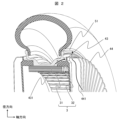
- Figure 1 is a cross-sectional image of the in-wheel motor 1 according to one embodiment of the present invention, as seen from the direction of vehicle travel.
- Figure 2 is a perspective cross-sectional view of the in-wheel motor 1 according to one embodiment of the present invention.
- the in-wheel motor 1 comprises a stator 2, a rotor 3, and a rotor housing 4 as components.
- a power conversion device (not shown) may be disposed inside the rotor housing 4, but in this embodiment, the power conversion device is mounted on the vehicle body side.
- the stator 2 has a stator core 21 and a coil 22, and the rotor 3 has a rotor core 31 and a magnet 32.
- the rotor core 31 is disposed on the outer periphery side of the stator core 21 so that its inner periphery surface faces the inner periphery surface of the stator core 21.
- the stator core 21 is supported from the inner diameter side by a stator housing (not shown).
- stator core 21 is covered by the stator housing.
- the coil 22 is wound around the stator core 21.
- the coil 22 may be wound in any manner, including concentrated winding, distributed winding, and alpha winding.
- the wire may be either round wire or rectangular wire.
- the stator 2 and rotor 3 are configured so that the outer peripheral surface of the rotor core 31 faces the inner peripheral surface of the stator core 21; in other words, the inner rotor is outside the scope of this invention.
- the power conversion device performs switching operations to convert DC power supplied from a battery (not shown) into three-phase AC power.
- This three-phase AC power is supplied to the stator windings of the stator 2, which generates a rotating magnetic field in the stator 2.
- the rotating magnetic field generated in the stator 2 drives the rotor 3 to rotate.
- the in-wheel motor 1 is housed on the inner periphery of the wheel 5 and is connected to the wheel 5 via the rotor housing 4.
- the wheel 5 has a tire mounting portion 51 and a central portion 52.
- the outer periphery of the rotor core 31 is fixed to the inner periphery of the central portion 52 by shrink fitting, adhesive, leaf springs, bolts, etc.
- the wheel 5 is manufactured by pressing or drawing steel materials, or by casting, die casting, forging, machining, etc. of light metals such as aluminum. It may be constructed as one piece, or it may be divided into two or three parts in the axial direction and assembled after molding. Unlike conventional wheels, there are no spokes to support the weight of the vehicle and transmit rotation, and the rotor housing 4 also serves the role of the spokes.
- a tire 6 is attached to the wheel 5.
- the tire 6 is selected from conventional tires available on the market to match the rim diameter and rim width of the wheel.
- the rotor housing 4 is manufactured by casting, die-casting, forging, machining, etc. of light metals such as aluminum. It may be manufactured by press molding or drawing of steel-based materials, but casting or die-casting of light metals is preferable because it is difficult to configure the cooling fins described below. It is preferable to configure it as a single unit because it forms the boundary between the inside of the in-wheel motor 1 and the atmosphere and has dustproof and waterproof functions. In this embodiment, since it is assumed that heat will be dissipated from the outer surface of the rotor housing 4 into the atmosphere, the material of the rotor housing 4 must have high thermal conductivity. Resins with high thermal conductivity are also candidates, but metal is preferable from the viewpoint of thermal conductivity. As an example, the thermal conductivity of resins with high thermal conductivity is at most about 5 W/(m ⁇ K), while the thermal conductivity of aluminum is about 240 W/(m ⁇ K).
- the rotor housing 4 is made up of a cylindrical section 41 and a side plate section 42 that seal the space between the wheel 5 and the axle (not shown), with annular fins 43 on the cylindrical section 41 and multiple radial fins 44 on the side plate section 42.
- Heat is transferred from the motor's heat-generating parts, such as the core and coils, to the cylindrical section 41 or the side plate section 42, and is ultimately dissipated into the atmosphere via the fins. From the standpoint of thermal conduction, therefore, it is desirable that the annular fins 43 and radial fins 44 be molded integrally with the cylindrical section 41 and the side plate section 42.
- the annular area surrounded by the annular fin 43, the tire mounting portion 51 of the wheel 5, and three sides of the cylindrical portion 41 is the annular flow passage 431.
- wind does not flow into the annular flow passage 431, and the cooling effect is weak.
- the wind from the vehicle's movement flows into the flow passage, increasing the cooling effect.
- the radial region surrounded by two adjacent radial fins 44 and three surfaces of the side plate portion 42 is the radial flow path 441.
- a radial flow 451 is generated by the centrifugal fan.
- the air in the radial flow path 441 is pushed outward by centrifugal force, and new air flows into the radial flow path 441 from the inner side. This air flow is called the centrifugal fan effect, and heat is transferred from the radial fins 44 to the air in the radial flow path 441 by this air flow.
- the rotor 3 is provided with a rotating shaft.
- the direction along the axis of the rotating shaft will be referred to as the "axial direction.”
- the terms “circumferential direction” and “radial direction” refer to the “circumferential direction” and “radial direction” of the in-wheel motor 1 (stator core, rotor core) unless otherwise specified.
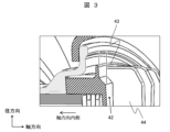
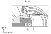
- FIGS 3 and 13 are enlarged cross-sectional views of an annular fin 43 according to one embodiment of the present invention.
- the annular fin 43 is formed on the circumferential outer surface of the in-wheel motor 1, and forms an annular flow path 431, which is a flow path through which air flows between the annular fin 43 and the tire mounting portion 51.
- the radial fins 44 are formed radially on the axial outer surface of the in-wheel motor 1. In this embodiment, the radial fins 44 extend radially and are connected to the annular fin 43. That is, the radial outermost part of the radial fin 44 is larger than the inner diameter of the annular fin 43 and smaller than the outer diameter, and is configured to connect the radial fin 44 and the annular fin 43.
- the radial fins 44 are connected to the annular fins 43 and become longer in the radial direction, which increases the centrifugal force and improves the flow rate in the radial flow passages 441, thereby improving the heat transfer rate from the radial fins 44 to the atmosphere.
- the support at the end of the side plate portion 42 becomes closer to fixed support rather than pin support, improving rigidity.
- the annular fins 43 are positioned axially inward from the outermost periphery of the side plate portion 42 of the housing of the in-wheel motor 1. This, as above, lengthens the radial flow paths 441, leading to improved heat transfer coefficient of the radial fins 44 and improved rigidity around the connection between the cylindrical portion 41 and the side plate portion 42.
- a sloped surface 42a is formed between the side plate portion 42 and the cylindrical portion 41.
- the pressure is lower radially outside of the sloped surface 42a, so the air flows along the sloped surface 42a.
- this portion By making this portion a slope rather than a right angle, the heat transfer coefficient of the sloped surface increases due to the flow following the slope. If it were a right angle, the flow would not follow the cylindrical portion 41 (the flow would not turn at a right angle), and the flow would separate near the cylindrical portion 41, remaining at low pressure, and there would be little improvement in the heat transfer coefficient of the cylindrical portion 41.
- the angle between the sloped surface 42a and the side plate 42 is preferably 45 degrees or less. The smaller this angle, the less separation of the flow in the radial flow passages 441 (the flow moving away from the wall and low pressure near the wall) occurs, and the more the heat transfer coefficient of the sloped surface 42a improves.
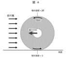
- Figure 4 is an image of the wind that a tire receives.
- the flow rate and flow speed of all radial flow paths are uniform.
- the relative speed between the outer periphery of the tire and the surrounding air becomes circumferential speed T.
- the circumferential speed is in the opposite direction to the direction of travel, so the relative speed with the surrounding air is zero.
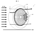
- Figure 5 is an image of the air flow near the in-wheel motor 1.
- the airflow speed is fast above the rotor housing 4, which has a large effect on heat transfer, so by forming a circumferential flow path in this area, i.e., annular flow path 431, the flow speed within the flow path can be increased and heat dissipation performance can be improved.
- the airflow in the radial flow paths 441 and the airflow from the vehicle face each other, so the cooling effect of the radial flow paths 441 decreases.
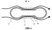
- Figure 6 is a cross-sectional view taken along the line A-A in Figure 5.
- the axial width of the tire 6 is greater than the axial width of the tire mounting portion 51.
- the annular flow passage 431 is hidden by the tire 6 and cannot be seen.
- the running wind flows along the tire 6 and wheel 5 as shown by the arrows in the figure. This is because if the running wind expanded by the axial width of the tire 6 flows rearward as it is, the pressure will be low near the annular fin 43 of the wheel 5, and the pressure difference will cause the running wind to bend and flow along the contour.
- the cross section of the tire 6 it has a streamlined shape, and flows into the annular flow passage 431 without separation.
- Figure 7 is an example of an analysis of the wind generated when the vehicle is traveling at 30km/h.
- the flow velocity streamlines are shown. It can be seen that the flow in the annular channel is large from the front to the top, and that the wind flows from the front into the annular channel 431 and flows all the way to the top. At the rear, it can be seen that there is almost no flow in the annular channel 431, and that the flow velocity in the radial channel 441 is large.
- the tire and wheel are modeled alone, but the flow patterns in the annular channel 431 and radial channel 441 do not change significantly even when fenders, suspension arms, etc. are taken into account.
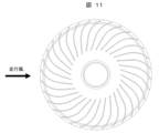
- Figures 8 to 11 show modified examples of radial fins 44.
- Figure 8 shows an example in which fins of the same length are arranged radially around the axis of rotation.
- Figure 9 shows a modified example in which fins of different lengths are arranged in a staggered fashion.
- the length of the fins 44a can be increased, leading to an increase in surface area and allowing them to function as reinforcing ribs on the inner diameter side where strength is required structurally. If all the radial fins are made longer, the spacing between the fins on the inner diameter side becomes narrower and it is not possible to increase the number of fins, but by combining short fins 44b, it is possible to increase the number of radial fins on the outer diameter side, where the centrifugal fan effect is greater.
- Figure 10 shows a modified example in which the fins are arranged diagonally relative to the radial direction.
- the length of the fins can be increased, which leads to an increase in surface area and also makes it difficult for the radial flow and the running wind to oppose each other in the area from the front to the top, which increases the flow speed of the radial flow paths 441 and improves heat dissipation performance.
- Figure 11 shows a modified example in which the outer diameter side of the radial fins is made into an arc. This makes the air flow smoother near the outlet of the radial flow passages 441, which leads to improved flow speed and reduced windage loss due to rotation.
- Figs. 8 to 11 are examples of working examples and are not intended to limit the structure. Also, it is possible to configure them in combination with each other.
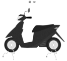
- FIG. 12 is an image of the motor mounted on a motorcycle.
- the in-wheel motor 1 may be mounted on the front and rear wheels, or only on the front wheel or only on the rear wheel.
- the motor can be applied to any in-wheel motor 1 in which the rotor housing 4 is exposed on the outermost surface.
- small mobility vehicles are conceivable.
- the upper part of the wheel where the flow speed becomes relatively faster due to the movement of the tire, is cooled by the circumferential flow of the annular flow path, thereby improving the cooling performance.
- the present invention is not limited to the above-described embodiments, but includes various modified examples.
- the above-described embodiments have been described in detail to clearly explain the present invention, and the present invention is not necessarily limited to those including all of the configurations.
Landscapes
- Engineering & Computer Science (AREA)
- Power Engineering (AREA)
- Chemical & Material Sciences (AREA)
- Combustion & Propulsion (AREA)
- Transportation (AREA)
- Mechanical Engineering (AREA)
- Motor Or Generator Cooling System (AREA)
- Arrangement Or Mounting Of Propulsion Units For Vehicles (AREA)
Abstract
本発明の目的は、インホイールモータにおいて、走行風による風の流れを利用して放熱性能を向上することにある。 上記目的を達成するために、本発明のインホイールモータは、ホイール内に収納されるインホイールモータにおいて、前記ホイールは、タイヤが搭載されるタイヤ搭載部と、前記インホイールモータの周方向の外面に形成され、前記タイヤ搭載部との間に空気が流れる流路を形成する円環状フィンとを備えることを特徴とする。
Description
本発明は、インホイールモータに関する。
特開2014-177167号公報(特許文献1)には、アウターロータ型のインホイールモータが記載されている(要約及び段落0008)。すなわち、このインホイールモータは、回転子である円環状のロータコアと、ロータコアの内周面側に固定された磁石と、ロータコアの外周を覆うケースとを備えている。そのケースは、底面の外表面に放射状に伸びたフィンが立設しており、インホイールモータをホイールの内側に配置したときに、ケースの底面がホイールの正面部に対向し、ホイールの内周面とケースの外周面との間に、インホイールモータの前側空間と後側空間とを繋ぐ流路が形成される。
このように、ケースにフィンが形成されていることにより、ケースは放熱体として作用するだけでなく、遠心ファンとしても作用する。さらに、ケースはロータコアの外周を覆うともに、インホイールモータの前側空間と後側空間とを繋ぐ流路が形成されているので、遠心ファン作用により、ホイールの外部の空気がケースの外周面を経てホイールを通過する空気流が生じる。この空気流により、フィン間に新たな外気が絶えず導入され、フィンによる放熱効果が高まる(段落0009)。
しかしながら、特許文献1の冷却構造では、ホイールが回転した時の遠心ファン効果による流れで冷却しており、走行風による影響は考慮されていない。
本発明の目的は、インホイールモータにおいて、走行風による風の流れを利用して放熱性能を向上することにある。
上記目的を達成するために、本発明のインホイールモータは、ホイール内に収納されるインホイールモータであって、前記ホイールは、タイヤが搭載されるタイヤ搭載部と、前記インホイールモータの周方向の外面に形成され、前記タイヤ搭載部との間に空気が流れる流路を形成する円環状フィンを備える。
本発明によれば、インホイールモータにおいて、走行風による風の流れを利用して放熱性能を向上することが可能となる。
以下の説明では、本発明に係る構成と、本発明との比較例に係る構成とを説明するが、同様な構成には同じ符号を付し、同様な説明の重複を避ける。また同じ符号を付した構成について差異がある場合は、その差異を説明する。
図1および図2を用いて、本発明の一実施例に係るインホイールモータ1について説明する。図1は、本発明の一実施例に係るインホイールモータ1の車両進行方向から見た断面イメージ図である。図2は、本発明の一実施例に係るインホイールモータ1の斜視断面図である。
インホイールモータ1は、構成部品として、固定子2と、回転子3と、ロータハウジング4と、を備える。ロータハウジング4の内部に電力変換装置(図示しない)を配置してもよいが、本実施例では電力変換装置は車体側に搭載している。固定子2は固定子コア21およびコイル22を有し、回転子3は回転子コア31および磁石32を有する。本実施例では、回転子コア31は、その内周面が固定子コア21の内周面と対向するように、固定子コア21の外周側に配置される。固定子コア21はステータハウジング(図示しない)に内径側から支持される。すなわち、固定子コア21の内周面はステータハウジングに覆われる。固定子コア21にはコイル22が巻回される。コイル22は、集中巻、分布巻、アルファ巻など、巻き方は限定されない。また、その素線も丸線、平角線のいずれでも良い。
固定子2と回転子3とは、回転子コア31の外周面が固定子コア21の内周面と対向するように配置される構成、すなわちインナーロータは本発明の範囲外とする。
電力変換装置は、スイッチング動作を行い、図示しないバッテリから供給される直流電力を3相交流電力に変換する。この3相交流電力は固定子2の固定子巻線に供給され、固定子2には回転磁界が発生する。固定子2に発生する回転磁界により、回転子3が回転駆動される。
インホイールモータ1は、ホイール5の内周側に収納され、ロータハウジング4を介してホイール5に接続される。ホイール5はタイヤ搭載部51と、中央部52を備える。本実施例では、回転子コア31の外周面が中央部52の内周面に、焼き嵌め、接着剤、板バネ、ボルトなどで固定される。
ホイール5は、鉄鋼系材料のプレス成型や絞り加工、もしくはアルミなどの軽金属の鋳造、ダイキャスト、鍛造、機械加工などで製造される。一体で構成しても良いし、軸方向に2~3の部品に分割して成型後に組み立てても良い。従来のホイールと異なり、車重を支えて回転を伝達するためのスポークはなく、ロータハウジング4がスポークの役割を兼ねる。
ホイール5にはタイヤ6が装着される。タイヤ6は市販されている従来タイヤの中から、当該ホイールのリム径およびリム幅に適合するものを選定する。
ロータハウジング4は、アルミなどの軽金属の鋳造、ダイキャスト、鍛造、機械加工などで製造される。鉄鋼系材料のプレス成型や絞り加工で製造してもよいが、後述する冷却フィンの構成が困難であるため、軽金属の鋳造やダイキャストが望ましい。インホイールモータ1内部と大気の境界となり、防塵防水の機能を有するため、一体で構成することが望ましい。本実施例では、ロータハウジング4の外表面から大気中への放熱を想定しているため、ロータハウジング4の材料は熱伝導率が高いことが求められる。高熱伝導の樹脂なども候補として挙がるが、熱伝導率の観点からは金属が望ましい。一例として、高熱伝導の樹脂の熱伝導率は最大でも5W/(m・K)程度、一方でアルミの熱伝導率は240W/(m・K)程度である。
ロータハウジング4は、ホイール5と車軸(図示しない)の間を密閉する、円筒部41と側板部42から成り、円筒部41には円環状フィン43が、側板部42には複数の放射状フィン44が構成される。コアやコイルなどモータ発熱部から円筒部41もしくは側板部42に熱が伝わり、最終的にフィンを介して大気中に放熱するので、熱伝導の観点から円環状フィン43と放射状フィン44は、円筒部41および側板部42と一体で成型されることが望ましい。
円環状フィン43と、ホイール5のタイヤ搭載部51と、円筒部41の3面で囲われた環状の領域が円環状流路431である。回転軸が静止してその場で回転しているような構造では、円環状流路431には風が流れ込まず冷却効果が薄い。しかしながら、タイヤなど回転しながら車両進行方向に進むようなものの場合、当該流路に走行風が流れ込むため冷却効果が高くなる。
隣り合う2枚の放射状フィン44と、側板部42の3面で囲われた放射状の領域が放射状流路441である。遠心ファンによる放射状の流れ451が発生している。ロータハウジング4が回転すると、放射状流路441内の空気が遠心力で外周側に押し出されて、内周側から新しい空気が放射状流路441に流入する。この風の流れを遠心ファン効果と称し、この風の流れにより放射状フィン44から放射状流路441内の空気に熱伝達する。
回転軸が静止してその場で回転しているような構造では、全ての放射状流路441で同じ風速、同じ放熱量となるが、タイヤなど回転しながら車両進行方向に進むようなものの場合、タイヤ前方では放射状流路内の流れと走行風が逆方向となるため風速が遅くなる。詳細は図4を用いて後述する。
回転軸が静止してその場で回転しているような構造では、全ての放射状流路441で同じ風速、同じ放熱量となるが、タイヤなど回転しながら車両進行方向に進むようなものの場合、タイヤ前方では放射状流路内の流れと走行風が逆方向となるため風速が遅くなる。詳細は図4を用いて後述する。
図1および図2では図示していないが、回転子3には回転軸が設けられる。以下の説明において、回転軸の軸心に沿う方向を「軸方向」と呼んで説明する。また「周方向」及び「径方向」は、特に断りのない場合、インホイールモータ1(固定子コア、回転子コア)の「周方向」及び「径方向」を示すものとする。
図3及び図13は、本発明の一実施例に係る円環状フィン43の拡大断面図である。円環状フィン43は、インホイールモータ1の周方向の外面に形成され、タイヤ搭載部51との間に空気が流れる流路である円環状流路431を形成している。放射状フィン44は、インホイールモータ1の軸方向の外面に放射状に形成される。本実施例では、放射状フィン44は径方向に延長され、円環状フィン43と接続される。すなわち、放射状フィン44の径方向の最も外側は、円環状フィン43の内径よりも大きく、外径以下とし、放射状フィン44と円環状フィン43とを接続するよう構成している。
このように、放射状フィン44が円環状フィン43と接続され、径方向に沿って長くなり、遠心力が大きくなり放射状流路441内の流速が向上し、それに伴い放射状フィン44から大気への熱伝達率が向上する。また、円筒部41の径方向剛性を向上する円環状フィン43と、側板部の軸方向剛性を向上する放射状フィン44を接続することで、梁モデルとして考えた時、側板部42端部の支持がピン支持から固定支持に近くなり剛性が向上する。これにより、放射状フィン44の熱伝達率向上、円筒部41と側板部42の接続部周辺の剛性向上に繋がる。従って、冷却効率が高くなり、ハウジングの材料変更が可能となり、軽量高剛性のロータハウジングを提供することも可能である。
次に、図3に示すよう、円環状フィン43はインホイールモータ1のハウジングの側板部42の最外周部よりも軸方向内側に配置される。これにより上記と同様に放射状流路441が長くなり、放射状フィン44の熱伝達率向上、円筒部41と側板部42の接続部周辺の剛性向上に繋がる。
また、図13に示すよう、側板部42と円筒部41の間には、斜面部42aが形成される。放射状流路441を空気が流れると、斜面部42aの径方向外側は圧力が低くなるので斜面部42aに沿って空気が流れる。当該部を直角ではなく斜面とすることで斜面に沿う流れにより、斜面部の熱伝達率も高くなる。直角だと円筒部41に沿う(流れが直角に曲がる)ことはなく、円筒部41付近は流れが剥離し低圧のままで、当該円筒部41の熱伝達率の向上は少ない。
この斜面により、放射状フィン44の熱伝達率が向上し、放熱性能の向上に繋がる。斜面部42aと側板部42の成す角は45度以下が望ましい。この角度が小さい方が放射状流路441の流れの剥離(壁から流れが離れて壁付近が低圧になること)が少なくなるので、斜面部42aの熱伝達率がより向上する。
図4は、タイヤが受ける風のイメージ図である。回転軸が移動せずその場で回転する遠心ファンのようなものの場合、全ての放射状流路の流量や流速は均一である。一方で、タイヤなど回転しながら車両進行方向に進むようなものの場合、自然風などを考えなければ進行方向速度と同じ風速の走行風(向かい風)を受ける。回転することによりタイヤ外周部の周辺空気との相対速度は周速Tとなる。タイヤ上方では、周速が進行方向と同じ向きになるので、周辺空気との相対速度は、周速T(=進行速度)の2倍の2Tとなる。タイヤ下方では、周速が進行方向と逆向きになるので、周辺空気との相対速度は、ゼロである。
図5は、インホイールモータ1近傍の風の流れのイメージである。前述のように、ロータハウジング4上方は、走行風の流速が速く、熱伝達への影響が大きいので、この部分に周方向の流路、つまり円環状流路431を構成することで、流路内の流速を高めて放熱性能を向上することができる。一方で前方から上方にかけては、放射状流路441の風の流れと走行風が対向するので、放射状流路441の冷却効果は落ちる。
ロータハウジング4後方は、放射状流路441の風の流れと走行風が同方向となるため、遠心ファン効果による放射状流れの影響が大きくなる。ロータハウジング4下方は、進行方向の相対速度が低くなるので、走行風による冷却は期待できないが、放射状流れにより冷却される。
このように、タイヤが移動することにより相対的に流速が速くなるロータハウジング4上方は円環状流路431の周方向流れで冷却、周方向流れが小さいホイール後方は放射状流路441の径方向流れで冷却することで、空気の流れに沿ったフィンにより熱伝達率が向上し、冷却効果が高まる。
図6は、図5の矢視A-Aの断面図である。一般的にタイヤ6の軸方向幅はタイヤ搭載部51の軸方向幅よりも大きい。このため、進行方向正面から見た時、円環状流路431はタイヤ6に隠れて見えない。しかしながら、飛行機の羽と同じように、図中の矢印のように、走行風はタイヤ6とホイール5に沿って流れる。これは、タイヤ6の軸方向幅で拡大された走行風がそのまま後方に流れるとホイール5の円環状フィン43付近が低圧になり、その圧力差によって走行風が曲げられて輪郭に沿って流れるからである。タイヤ6の断面を見ると流線形になっており、剥離なども起きずに円環状流路431に流入する。
図7は、時速30km/hの時の走行風の解析例である。流速の流線を示している。前方から上方では、円環状流路の流れが大きく、前方から円環状流路431に走行風が流入し、上方まで流れることが確認できる。後方では、円環状流路431の流れはほとんどなく、放射状流路441の流速が大きいことが確認できる。本解析例では、タイヤ・ホイール単独でモデル化しているが、フェンダーやサスペンションアームなどを考慮しても円環状流路431や放射状流路441の流れの様子は概ね変わらない。
図8から図11は、放射状フィン44の変形例を示す。図8は、同じ長さのフィンを、回転軸を中心に放射状に並べた実施例である。
図9は、長さ違いのフィンを互い違いに並べた変形例である。この構成にすることで、フィン44aの長さを長くし、表面積拡大に繋がるとともに、構造上強度が必要な内径側の補強リブとしての機能を持たせることができる。全ての放射状フィンを長くすると、内径側でフィン同士の間隔が狭くなり、フィンの数を増やせないが、短いフィン44bを組み合わせることで、遠心ファン効果が大きくなる外径側の放射状フィンを増加することができる。
図10は、フィンを放射線に対して斜めに配置した変形例である。斜めに配置することでフィンの長さを長くすることができ、表面積拡大に繋がるとともに、前方から上方にかけての領域で放射状流れと走行風が対向しにくくなるので、放射状流路441の流速が上がり放熱性能が向上する。
図11は、放射状フィンの外径側を円弧にした変形例である。放射状流路441の出口近辺の風の流れがスムーズになり、流速の向上や回転による風損の低減に繋がる。
図8から図11は実施例の1例であり、構造を限定するものではない。また、それぞれを組み合わせて構成することも可能である。
図12は、二輪車への搭載イメージである。当該図のように、前後輪にインホイールモータ1を搭載してもよいし、前輪だけ、後輪だけに搭載してもよい。二輪車以外にも、ロータハウジング4が最外面に露出しているようなタイプのインホイールモータ1であれば適用可能である。例えば、小型モビリティなどが考えられる。四輪のインホイールモータ1の場合には、メンテナンスや互換性の観点から、インホイールモータ1の外側に従来ホイールを被せることが一般的であるため、そのような走行風が直接当たらない構造には適用できない。
以上のように、タイヤが移動することにより相対的に流速が速くなるホイール上方は円環状流路の周方向流れで冷却することにより、冷却性能を向上することができる。
以上のように、タイヤが移動することにより相対的に流速が速くなるホイール上方は円環状流路の周方向流れで冷却することにより、冷却性能を向上することができる。
なお、本発明は上記した各実施例に限定されるものではなく、様々な変形例が含まれる。例えば、上記した実施例は本発明を分かりやすく説明するために詳細に説明したものであり、必ずしも全ての構成を備えるものに限定されるものではない。また、実施例の構成の一部について、他の構成の追加・削除・置換をすることが可能である。
1…インホイールモータ、2…固定子、3…回転子、4…ロータハウジング、6…タイヤ41…円筒部、42…側板部、43…円環状フィン、431…円環状流路、
44…放射状フィン、441…放射状流路、5…ホイール、51…タイヤ搭載部、
52…中央部、
44…放射状フィン、441…放射状流路、5…ホイール、51…タイヤ搭載部、
52…中央部、
Claims (7)
- ホイール内に収納されるインホイールモータにおいて、
前記ホイールは、タイヤが搭載されるタイヤ搭載部と、
前記インホイールモータの周方向の外面に形成され、前記タイヤ搭載部との間に空気が流れる流路を形成する円環状フィンとを備えることを特徴とするインホイールモータ。 - 請求項1に記載のインホイールモータにおいて、
前記インホイールモータの軸方向の外面に放射状に形成される放射状フィンを備えることを特徴とするインホイールモータ。 - 請求項2に記載のインホイールモータにおいて、
前記放射状フィンと前記円環状フィンとを接続することを特徴とするインホイールモータ。 - 請求項3に記載のインホイールモータにおいて、
前記円環状フィンを前記インホイールモータのハウジングの側板部の最外周部よりも軸方向内側に配置することを特徴とするインホイールモータ。 - 請求項4に記載のインホイールモータにおいて、
前記円環状フィンが配置される円筒部と、前記放射状フィンが配置される前記側板部とを備え、前記円筒部と前記側板部の間に斜面部を形成することを特徴とするインホイールモータ。 - 請求項5に記載のインホイールモータにおいて、
前記斜面部は、前記側板部と45度以下で交差するよう構成することを特徴とするインホイールモータ。 - 請求項3乃至請求項6のいずれか1項に記載のインホイールモータにおいて、
前記円環状フィンの外径を前記放射状フィンの外径よりも大きくすることを特徴とするインホイールモータ。
Applications Claiming Priority (2)
| Application Number | Priority Date | Filing Date | Title |
|---|---|---|---|
| JP2023205831A JP2025090929A (ja) | 2023-12-06 | 2023-12-06 | インホイールモータ |
| JP2023-205831 | 2023-12-06 |
Publications (1)
| Publication Number | Publication Date |
|---|---|
| WO2025120902A1 true WO2025120902A1 (ja) | 2025-06-12 |
Family
ID=95980755
Family Applications (1)
| Application Number | Title | Priority Date | Filing Date |
|---|---|---|---|
| PCT/JP2024/026615 Pending WO2025120902A1 (ja) | 2023-12-06 | 2024-07-25 | インホイールモータ |
Country Status (2)
| Country | Link |
|---|---|
| JP (1) | JP2025090929A (ja) |
| WO (1) | WO2025120902A1 (ja) |
Citations (4)
| Publication number | Priority date | Publication date | Assignee | Title |
|---|---|---|---|---|
| JP2011519544A (ja) * | 2008-04-18 | 2011-07-07 | クリエーション アンド モーター インダストリーズ リミテッド | アウターローター型モーター及びこの構造を適用したアウターローター型インホイールモーター |
| JP2014177167A (ja) * | 2013-03-14 | 2014-09-25 | Okayama Prefecture Industrial Promotion Foundation | インホイールモータ |
| JP2019018839A (ja) * | 2017-07-18 | 2019-02-07 | Ntn株式会社 | 車両用動力装置および発電機付き車輪用軸受装置 |
| CN114801703A (zh) * | 2022-06-02 | 2022-07-29 | 大富科技(安徽)股份有限公司 | 轮毂电机、车轮及车辆 |
-
2023
- 2023-12-06 JP JP2023205831A patent/JP2025090929A/ja active Pending
-
2024
- 2024-07-25 WO PCT/JP2024/026615 patent/WO2025120902A1/ja active Pending
Patent Citations (4)
| Publication number | Priority date | Publication date | Assignee | Title |
|---|---|---|---|---|
| JP2011519544A (ja) * | 2008-04-18 | 2011-07-07 | クリエーション アンド モーター インダストリーズ リミテッド | アウターローター型モーター及びこの構造を適用したアウターローター型インホイールモーター |
| JP2014177167A (ja) * | 2013-03-14 | 2014-09-25 | Okayama Prefecture Industrial Promotion Foundation | インホイールモータ |
| JP2019018839A (ja) * | 2017-07-18 | 2019-02-07 | Ntn株式会社 | 車両用動力装置および発電機付き車輪用軸受装置 |
| CN114801703A (zh) * | 2022-06-02 | 2022-07-29 | 大富科技(安徽)股份有限公司 | 轮毂电机、车轮及车辆 |
Also Published As
| Publication number | Publication date |
|---|---|
| JP2025090929A (ja) | 2025-06-18 |
Similar Documents
| Publication | Publication Date | Title |
|---|---|---|
| CN1808857B (zh) | 轮内马达 | |
| JP4391884B2 (ja) | 車両用ホイール駆動装置 | |
| JP7635750B2 (ja) | インホイールモータの冷却構造 | |
| JP5534934B2 (ja) | インホイールモータ冷却構造 | |
| KR20150127799A (ko) | 인휠 시스템의 휠 어셈블리 | |
| JP2007515147A (ja) | 通気を行うための手段を備える電磁制動機 | |
| EP2748912A1 (en) | Wheel motor configuration for vehicle motorization | |
| CN113799595A (zh) | 一种集成轮毂电机与轮辋、制动器的车轮总成 | |
| JP7236816B2 (ja) | 車両用動力装置および発電機付き車輪用軸受装置 | |
| KR20140037356A (ko) | 인휠 모터 냉각 시스템 | |
| JP2019521026A (ja) | 車両用駆動ユニットを有するホイール、ホイールの取り付け方法、及びホイールの軸受装置をシールするためのシール装置 | |
| JP2025090929A (ja) | インホイールモータ | |
| US6491139B1 (en) | Fluid-cooled brake system | |
| JP7189486B2 (ja) | インホイールモータ駆動装置 | |
| JP2020114054A (ja) | インホイールモータ | |
| WO2022123951A1 (ja) | 電動ホイール | |
| JP6098872B2 (ja) | インホイールモータ | |
| CN219304640U (zh) | 电机罩 | |
| KR102668841B1 (ko) | 내부공기 순환형 인휠 모터 | |
| CN111864932A (zh) | 一种便于散热的轮毂电机 | |
| CN216969199U (zh) | 车轮组件及具有其的车辆 | |
| CN203206038U (zh) | 一种电动汽车驱动电机 | |
| CN212509296U (zh) | 一种随动闸组件和乘骑车 | |
| JP2015113076A (ja) | タイヤ・ホイール組立体 | |
| US20250303849A1 (en) | Combined motor rotor and wheel rim assembly |
Legal Events
| Date | Code | Title | Description |
|---|---|---|---|
| 121 | Ep: the epo has been informed by wipo that ep was designated in this application |
Ref document number: 24900200 Country of ref document: EP Kind code of ref document: A1 |
|
| NENP | Non-entry into the national phase |
Ref country code: DE |