WO2025115803A1 - 吸収性物品の製造装置及び製造方法 - Google Patents
吸収性物品の製造装置及び製造方法 Download PDFInfo
- Publication number
- WO2025115803A1 WO2025115803A1 PCT/JP2024/041625 JP2024041625W WO2025115803A1 WO 2025115803 A1 WO2025115803 A1 WO 2025115803A1 JP 2024041625 W JP2024041625 W JP 2024041625W WO 2025115803 A1 WO2025115803 A1 WO 2025115803A1
- Authority
- WO
- WIPO (PCT)
- Prior art keywords
- continuous material
- drum
- cutting
- conveying
- manufacturing
- Prior art date
- Legal status (The legal status is an assumption and is not a legal conclusion. Google has not performed a legal analysis and makes no representation as to the accuracy of the status listed.)
- Pending
Links
Images




Classifications
-
- A—HUMAN NECESSITIES
- A61—MEDICAL OR VETERINARY SCIENCE; HYGIENE
- A61F—FILTERS IMPLANTABLE INTO BLOOD VESSELS; PROSTHESES; DEVICES PROVIDING PATENCY TO, OR PREVENTING COLLAPSING OF, TUBULAR STRUCTURES OF THE BODY, e.g. STENTS; ORTHOPAEDIC, NURSING OR CONTRACEPTIVE DEVICES; FOMENTATION; TREATMENT OR PROTECTION OF EYES OR EARS; BANDAGES, DRESSINGS OR ABSORBENT PADS; FIRST-AID KITS
- A61F13/00—Bandages or dressings; Absorbent pads
- A61F13/15—Absorbent pads, e.g. sanitary towels, swabs or tampons for external or internal application to the body; Supporting or fastening means therefor; Tampon applicators
Definitions
- the present invention relates to an apparatus and method for manufacturing absorbent articles.
- Patent Document 1 WO 2018/212092
- a manufacturing device and method for absorbent articles are known in which a continuous material that is stretchable in the conveying direction is conveyed while tension is applied in the conveying direction, and the conveyed continuous material is cut to form individual absorbent articles.
- Patent Document 1 WO 2018/212092
- the manufacturing device disclosed in Patent Document 1 can adjust the amount of expansion and contraction of the continuous material by changing the tension applied to the transported continuous material, thereby responding to changes in product size, thereby reducing the amount of work required when changing the size of the product.
- the continuous material when using such elastic continuous material, if the continuous material stretches or shrinks beyond the desired length for some reason, during the cutting process in which the continuous material is cut to a length appropriate for the size of the absorbent article, the continuous material may be cut at a position other than the intended cutting point, and a product with the desired shape may not be obtained. There is a possibility that such problems may not be detected immediately when they occur.
- An absorbent article manufacturing apparatus comprises a first drum, a second drum, a cutting device, and a detection device.
- the first drum transports the continuous material.
- the second drum receives the continuous material transported by the first drum and transports the continuous material further.
- the cutting device is disposed opposite the second drum and cuts a predetermined portion of the continuous material to form an absorbent article.
- the detection device detects the cut portion of the continuous material transported by the first drum or the second drum upstream of the location where the continuous material is cut by the cutting device in the transport direction of the continuous material.
- the manufacturing method for absorbent articles includes a first conveying step, a second conveying step, a cutting step, and a detection step.
- first conveying step the continuous material is conveyed by the first drum.
- second conveying step the continuous material conveyed by the first drum is further conveyed by the second drum.
- cutting step a predetermined portion of the continuous material is cut by a cutting device disposed opposite the second drum to form an absorbent article.
- detection step a detection device detects the cut portion of the continuous material conveyed by the first drum or the second drum upstream of the location where the continuous material is cut by the cutting device in the conveying direction of the continuous material.
- the absorbent article manufacturing device and manufacturing method of the present invention can detect early misalignment of the cutting location (misalignment of the planned cutting location at the detection location and misalignment of the location that will actually be cut by the cutting device) based on the image.
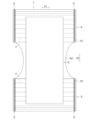
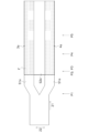
- FIG. 1 is a front view showing a schematic illustration of a disposable diaper, which is an example of an absorbent article manufactured by the absorbent article manufacturing apparatus of the present invention.
- FIG. 2 is a diagram illustrating the disposable diaper of FIG. 1 with the side seal portion unfolded.
- 1 is a block diagram showing an absorbent article manufacturing apparatus according to an embodiment of the present invention together with a process flow.
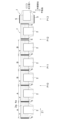
- 3A to 3C are schematic process diagrams illustrating some of the steps of a method for manufacturing a wearing article according to one embodiment.
- 4B is a schematic process diagram showing a part of the process of the manufacturing method of the wearing article of the embodiment, which is a continuation of the process shown in FIG. 4A.
- FIG. 4C is a schematic process diagram showing a part of the process of the manufacturing method of the wearing article of the embodiment, which is a continuation of the process shown in FIG. 4B.
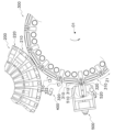
- FIG. 4 is a side view illustrating a portion of the manufacturing apparatus of FIG. 3 (the first drum, the second drum, the imaging device, and the cutting device).
- FIG. 6 is an enlarged view of the cutting device and its periphery in FIG. 5 .
- FIG. 2 is an enlarged view of the cutting device, and one of the auxiliary suction members and anvils of the second drum.
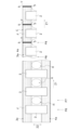
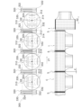
- the upper part is a diagram showing the second drum (the main suction member and the auxiliary suction member of the second drum) viewed along the radial direction of the second drum
- the lower part is a diagram showing the continuous material and diapers transported by the second drum depicted in the upper part, viewed along the radial direction of the second drum.
- FIG. 1 An example of an absorbent article manufactured by the manufacturing apparatus 100 according to one embodiment of the present invention will be described with reference to FIGS. 1 and 2.
- FIG. 1 An example of an absorbent article manufactured by the manufacturing apparatus 100 according to one embodiment of the present invention will be described with reference to FIGS. 1 and 2.
- FIG. 1 An example of an absorbent article manufactured by the manufacturing apparatus 100 according to one embodiment of the present invention will be described with reference to FIGS. 1 and 2.
- FIG. 1 is a schematic front view of a disposable diaper 1 (hereinafter simply referred to as diaper 1) that is an example of an absorbent article manufactured by the manufacturing apparatus 100.
- FIG. 2 is a diagram illustrating the diaper 1 with the side seal portion 5, which will be described later, deployed.
- the absorbent article will be described using a disposable diaper 1 as an example.
- the absorbent article is not limited to a disposable diaper, as long as it has a member that absorbs liquid, such as an absorbent core described below, and is a wearable article that is formed by cutting a continuous material that is transported.
- the diaper 1 has a symmetrical structure. As shown in Figure 2, the diaper 1 mainly has an absorbent body 2, a front torso section 3, and a rear torso section 4.
- the absorbent body 2 extends between the front torso section 3 and the rear torso section 4, and is a member that covers the wearer's crotch.
- the front torso section 3 is a member that covers the front side of the wearer's torso
- the rear torso section 4 is a member that covers the back side of the wearer's torso.
- the absorbent body 2, front torso section 3, and rear torso section 4 that make up the diaper 1 will be described in detail below.
- the direction that extends around the wearer's waist when worn (the left-right direction in Figs. 1 and 2) is referred to as the waist direction X1
- the longitudinal direction of the absorbent body 2 that is, the direction perpendicular to the waist direction X1 is referred to as the vertical direction X2.
- the diaper 1 here is a pants-type diaper.
- the type of diaper is not limited to pants-type, and may be a tape-type diaper in which the front and rear torso sections are separate (not joined by side seal section 5) and are fastened together with tape when worn.
- the absorbent body 2 is folded in two at the middle in the vertical direction X2, and the left and right ends on both sides of the front torso section 3 in the waist circumference direction X1 overlap with the left and right ends on both sides of the rear torso section 4 in the waist circumference direction X1, as shown in FIG. 1.
- the end of the front torso section 3 in the waist circumference direction X1 and the end of the rear torso section 4 in the waist circumference direction X1 are joined at the side seal section 5 (see FIG. 1).
- the absorbent body 2 includes a top sheet, a back sheet, and an absorbent core disposed between the top sheet and the back sheet (not shown). Note that the structure of the absorbent body 2 shown here is merely an example, and the absorbent body 2 may include components other than the top sheet, the back sheet, and the absorbent core.
- the top sheet is a liquid-permeable sheet that is disposed on the wearer's skin side when worn.
- the back sheet is a liquid-impermeable sheet that is disposed on the opposite side to the top sheet (the outside that does not face the wearer's skin).
- the absorbent core is made of crushed pulp, or a mixture of crushed pulp and a highly absorbent polymer. The absorbent core absorbs bodily fluids such as urine of the wearer.
- the absorbent body 2 is a substantially rectangular member.
- the absorbent body 2 extends between the front torso section 3 and the rear torso section 4 with the longitudinal direction being the vertical direction X2.
- the absorbent body 2 is joined to the front torso section 3 at the center of the front torso section 3 in the waist circumference direction X1, and is joined to the rear torso section 4 at the center of the rear torso section 4 in the waist circumference direction X1.
- the front torso section 3 and the rear torso section 4 have an inner sheet S1 that faces the wearer's skin, and an outer sheet S2 that does not face the wearer's skin (that is, that is placed on the outside when worn by the wearer).
- the inner sheet S1 and the outer sheet S2 are laminated.
- the outer sheet S2 not only constitutes the front torso section 3 and the rear torso section 4, but also extends continuously to connect the front torso section 3 and the rear torso section 4.
- an elastic member F is arranged to fit the diaper 1 to the wearer.
- the elastic member F is arranged between the inner sheet S1 and the outer sheet S2, and in this state, the inner sheet S1 and the outer sheet S2 are joined.
- the elastic member F is also joined to at least one of the inner sheet S1 and the outer sheet S2.
- multiple rubber threads, flat rubber, or a material containing a thermoplastic resin can be used as the elastic member F.
- front torso section 3 and the rear torso section 4 may include members other than the inner sheet S1, the outer sheet S2, and the elastic member F.
- FIG. 3 is a block diagram showing the manufacturing apparatus 100 for the diaper 1 together with the process flow.
- Figs. 4A to 4C are each a schematic process diagram showing a part of the process of the manufacturing method for the diaper 1.
- Fig. 4B shows a continuation of the process in Fig. 4A
- Fig. 4C shows a continuation of the process in Fig. 4B. Note that the process described below is merely an example and may be modified as appropriate.
- the manufacturing device 100 mainly includes a sheet dividing and conveying device 110, an outer sheet band conveying device 120, an elastic member supplying device 130, a joining device 140, an elastic member nullifying device 150, an absorbent body joining device 160, a leg hole forming device 170, a folding device 180, a sheet joining device 190, a first drum 200, a second drum 300, an imaging device 400, a cutting device 500, a diaper conveying device 650, a discharge device 600, and a control device 700.
- the control device 700 is a computer having a CPU (not shown), memories such as ROM and RAM, auxiliary storage devices, input/output devices, various electrical and electronic components, etc. Note that the control device 700 does not have to be a single device, and multiple devices may work together to function as the control device 700.
- the control device 700 is electrically connected to the sheet dividing and conveying device 110, the outer sheet band conveying device 120, the elastic member supplying device 130, the joining device 140, the elastic member disabling device 150, the absorbent body joining device 160, the leg hole forming device 170, the folding device 180, the sheet joining device 190, the first drum 200, the second drum 300, the imaging device 400, the cutting device 500, the diaper conveying device 650, and the discharge device 600.
- the control device 700 controls the operations of the sheet dividing and conveying device 110, the outer sheet belt conveying device 120, the elastic member supplying device 130, the joining device 140, the elastic member nullifying device 150, the absorbent body joining device 160, the leg hole forming device 170, the folding device 180, the sheet joining device 190, the first drum 200, the second drum 300, the imaging device 400, the cutting device 500, the diaper conveying device 650, and the discharge device 600 by the CPU executing the programs stored in the memory.
- the control device 700 also functions as a detection device in the claims.
- control device 700 is described here as an example being a computer, as long as it is possible to cause the various devices 110, 120, 130, 140, 150, 160, 170, 180, 190, 200, 300, 400, 500, 600, 650 to perform the operations described below, or to execute the processes described below, the control device 700 may be realized by hardware (various electric and electronic circuits) or by a combination of software and hardware.
- the sheet splitting and conveying device 110 splits the continuously conveyed sheet, which is unwound from a wound sheet roll (not shown), into two pieces in a direction perpendicular to the conveying direction using a blade (not shown) to form a sheet-like inner sheet band S1a (step P1 in FIG. 4A).
- the conveying direction of the sheet is called the "conveying direction Z1".
- the direction perpendicular to the "conveying direction Z1" is called the "width direction Z2".
- the inner sheet band S1a is a sheet band in which the inner sheets S1 that constitute the front torso section 3 when the diaper 1 is formed are continuously joined in the longitudinal direction, or a sheet band in which the inner sheets S1 that constitute the rear torso section 4 when the diaper 1 is formed are continuously joined in the longitudinal direction.
- the sheet splitting and conveying device 110 conveys two inner sheet bands S1a formed by splitting one sheet in the same conveying direction Z1, with a predetermined gap between them in the width direction Z2.
- the sheet dividing and conveying device 110 conveys the elastic inner sheet strip S1a while applying a predetermined tension in the conveying direction Z1.
- the outer sheet band conveying device 120 conveys the sheet-like outer sheet band S2a (a continuous sheet that becomes the outer sheet S2 when formed into the diaper 1) unwound from a sheet roll (not shown) in the same direction (conveying direction Z1) as the two rows of inner sheet bands S1a (see step P2 in FIG. 4A).
- the outer sheet band conveying device 120 conveys the stretchable outer sheet band S2a while applying a predetermined tension in the conveying direction Z1.
- the two rows of inner sheet bands S1a transported by the sheet dividing and transporting device 110 are aligned so that one end (outer edge) of the inner sheet band S1a in the width direction Z2 overlaps each of both ends of the outer sheet band S2a in the width direction Z2.
- the two rows of inner sheet strips S1a transported by the sheet dividing and transporting device 110 may be aligned so that the end (outer edge) in the width direction Z2 of each inner sheet strip S1a is positioned inside the end (outer edge) in the width direction Z2 of the outer sheet strip S2a.
- the end in the width direction Z2 of the outer sheet strip S2a (the portion positioned outside the inner sheet strip S1a in the width direction Z2) may be folded back inward so as to overlap the absorbent body 2 in a later process to form a structure that prevents bodily fluids and the like from leaking out of the torso of the diaper 1. A detailed description of this embodiment will be omitted.
- the elastic member supplying device 130 supplies the elastic member F in a state stretched in the longitudinal direction between the inner sheet band S1a and the outer sheet band S2a (see step P3 in FIG. 4A).
- the elastic member supplying device 130 positions the elastic member F between the inner sheet band S1a and the outer sheet band S2a so as to be aligned with the conveying direction Z1.
- the manufacturing device 100 is described here in the order of the outer sheet band conveying device 120 and the elastic member supplying device 130.
- the elastic member F is supplied to the inner sheet band S1a or the outer sheet band S2a first, and then the other sheet band S2a, S1a is supplied, so that the elastic member F is sandwiched between the inner sheet band S1a and the outer sheet band S2a.
- the joining device 140 joins the elastic member F, the inner sheet band S1a, and the outer sheet band S2a at predetermined positions to form a continuous sheet 3a that will become the front torso section 3 when formed into the diaper 1, and a continuous sheet 4a that will become the rear torso section 4 when formed into the diaper 1 (see step P4 in FIG. 4A).
- a continuous sheet 3a is a sheet band in which the front torso section 3 is continuously joined in the longitudinal direction
- the continuous sheet 4a is a sheet band in which the front torso section 3 is continuously joined in the longitudinal direction.
- the elastic member nullifying device 150 performs a nullifying process to cut a part of the elastic member F at the location of the continuous sheets 3a, 4a where the absorbent body 2 is to be placed (see step P5 in FIG. 4A).
- the elastic member F may be cut using, for example, a blade or by fusing with heat.
- the absorbent body joining device 160 positions the absorbent body 2 across the continuous sheets 3a and 4a at the location where the elastic member disabling device 150 has disabled the elastic member F, and joins the continuous sheets 3a and 4a to the absorbent body 2 (see step P6 in FIG. 4B).
- means such as heat welding, ultrasonic welding, adhesives, etc. may be used for joining, although this is not limited thereto.
- the leg hole forming device 170 sandwiches the continuous sheets 3a, 4a and absorbent body 2 that have been integrated by the absorbent body joining device 160, for example, between an anvil roll and a die cut roll, and forms oval holes H in the outer sheet band S2a that will become leg holes for the diaper 1 (see step P7 in Figure 4B).
- the folding device 180 folds the absorbent body 2 at the center in the width direction Z2 and overlaps the continuous sheets 3a and 4a (see step P8 in FIG. 4B). Note that for convenience of illustration in FIG. 4B, the sheet is depicted as being discontinuous before and after folding by the folding device 180, but in reality, at this point, the sheet is not cut along the width direction Z2 and is continuous.
- the sheet joining device 190 joins the continuous sheets 3a and 4a in the laminated sheet-like material (integrated continuous sheets 3a, 4a, and outer sheet band S2a) in which the continuous sheets 3a and 4a are folded and conveyed by the folding device 180, in the width direction Z2 near the positions that will become both ends of the front torso section 3 and both ends of the rear torso section 4 when the diaper 1 is formed, to form the side seal section 5 (the side seal section 5 of each diaper 1) (see step P9 in FIG. 4B).
- the area where the side seal section 5 is formed is indicated by hatching.
- a means such as heat welding or ultrasonic welding is used for joining, although this is not limited thereto.
- the continuous sheets 3a, 4a, and outer sheet band S2a to which the absorbent body 2 is attached at a predetermined interval and joined at the side seal section 5 are referred to as a continuous material C.
- the cutting device 500 which will be described later, cuts the continuous material C at a midpoint between two adjacent side seal portions 5 in the conveying direction Z1 (sandwiched between two adjacent absorbent bodies 2 in the conveying direction Z1).
- the portion of the continuous material C that is to be cut by the cutting device 500 is referred to as the planned cutting portion Y.
- the planned cutting portion Y is drawn with a dashed line. Note that the dashed lines drawn in Figures 4B and 4C are imaginary lines and are not lines that are actually provided on the continuous material C.
- the first drum 200 is a device that transports continuous material C by rotating around a rotation axis.
- the first drum 200 comprises a plurality of suction members 210, 220 (see Figure 5), each having an suction surface capable of suctioning the continuous material C, a holding mechanism (not shown) that holds the plurality of suction members 210, 220 rotatably around a first axis, a drive device (not shown) having a rotating shaft (not shown) rotatable around a second axis parallel to the first axis and a connecting mechanism (not shown) that connects the rotating shaft and the suction members 210, 220, and a support mechanism (not shown) that supports the holding mechanism and the drive device, wherein the connecting mechanism is connected to the plurality of suction members 210, 220 in a state in which the plurality of suction members 210, 220 can move in the radial direction of a circle centered on the first axis, and the support mechanism is a sheet transport device that supports the holding mechanism and the drive device so that the holding mechanism and the drive device can move relatively in a direction perpendic
- the first drum 200 conveys the continuous material C in the conveying direction Z1 by rotating in the direction of the arrow (clockwise in Figure 5) while sucking the continuous material C onto the suction surfaces (outer peripheral surfaces) of the suction members 210, 220.
- the first drum 200 stretches and contracts the continuous material C while conveying it so that the continuous material C can be cut at the same pitch (at the same intervals) by the cutting device 500 in a subsequent process regardless of the size of the diaper 1.
- the first drum 200 adjusts the length of the conveyed continuous material C in the conveying direction Z1 so that the intervals between the intended cutting points Y in the continuous material C are a predetermined length regardless of the size of the diaper 1 to be manufactured.
- the first drum 200 changes the tension acting on the continuous material C in the conveying direction Z1 while conveying the continuous material C.
- a first drum 200 that allows the amount of expansion and contraction of the continuous material C to be adjusted, even if the size of the diaper 1 to be manufactured changes (for example, even when manufacturing diapers 1 of medium, large, and extra-large sizes using one manufacturing device 100), there is no need to replace the second drum in the downstream stage to match the size of the diaper 1.
- the first drum 200 shrinks the continuous material C, from which the distance between adjacent intended cutting points Y was A, to the distance between adjacent intended cutting points Y being B (see step P10 in FIG. 4C).
- the second drum 300 is a device that rotates around a rotation axis to transport the continuous material C.
- the second drum 300 When viewed along the rotation axis O1 (the rotation axis that rotates the main suction member 310 and the auxiliary suction member 320 described below), the second drum 300 has a roughly circular outer shape (see Figure 5).
- the second drum 300 receives the continuous material C (here, continuous material C with a distance B between adjacent intended cutting points Y) transported by the first drum 200 with the main suction member 310 and the auxiliary suction member 320 (see Figure 5), and while sucking the continuous material C with the suction surface 312 (outer peripheral surface) of the main suction member 310 and the suction surface 322 (outer peripheral surface) of the auxiliary suction member 320 (see Figure 6), rotates the main suction member 310 and the auxiliary suction member 320 around the rotation axis O1 to further transport the continuous material C.
- the continuous material C here, continuous material C with a distance B between adjacent intended cutting points Y
- the continuous material C transported by the second drum 300 has its intended cutting points Y cut by the cutting device 500 during transport, and individual diapers 1 are formed (see process P12 in Figure 4C).
- the expression "diaper 1 is molded" is not limited to the case where diaper 1 is in a finished state, and does not exclude, for example, the case where some accessories are attached to diaper 1 molded from continuous material C in a later process, or some processing is performed on diaper 1.
- the molded diaper 1 is further transported in the transport direction Z1 by the rotation of the main suction member 310 and the auxiliary suction member 320 about the rotation axis O1. Furthermore, while transporting the diaper 1, the second drum 300 rotates the diaper 1, which has been transported with the waist circumference direction X1 and the transport direction Z1 aligned, by 90 degrees to bring the vertical direction X2 and the transport direction Z1 into alignment (see step P13 in FIG. 4C). The second drum 300 then transports the diaper 1, with the vertical direction X2 and the transport direction Z1 aligned, further in the transport direction Z1 and hands it over to the diaper transport device 650. The second drum 300 will be described in detail later.
- the imaging device 400 is, for example, a camera that captures video. In the conveying direction Z1 of the continuous material C, the imaging device 400 captures an image of the continuous material C upstream of the cutting location of the continuous material C by the cutting device 500 described later (see process P11 in FIG. 4C).
- the control device 700 which is an example of a detection device, detects the cutting location (planned cutting location Y) of the continuous material C based on the image captured by the imaging device 400.
- the detection here is not limited to the case where the control device 700 detects the cutting location (planned cutting location Y) of the continuous material C itself by the cutting device 500, but may also detect a location (for example, the side seal portion 5 described later) where the cutting device 500 can identify the cutting location (planned cutting location) of the continuous material C.
- the imaging device 400 captures an image of the continuous material C conveyed by the second drum 300, as shown in FIG. 5.
- the imaging device 400 is installed in a position opposite the second drum 300 with its lens facing the second drum 300, and captures an image of the continuous material C being transported by the second drum 300.
- the imaging device 400 may also image the continuous material C being transported by the first drum 200.
- the imaging device 400 is installed at a position opposite the first drum 200 with its lens facing the first drum 200, and images the continuous material C being transported by the first drum 200.
- the imaging device 400 images at least the cutting portion (planned cutting portion Y) of the continuous material C where the cutting device 500 will cut. Specifically, for example, the imaging device 400 images the cutting portion (planned cutting portion Y) of the continuous material C where the cutting device 500 will cut the continuous material C and a pair of side seal portions 5 arranged on either side of the cutting portion in the conveying direction Z1 of the continuous material C.
- the imaging device 400 may image the entire continuous material C passing in front of the lens of the imaging device 400.
- the imaging device 400 may also image only a portion of the side seal portions 5 in the width direction Z2.
- the cutting device 500 is disposed opposite the second drum 300 and is a device that cuts a predetermined portion (planned cutting portion Y) of the continuous material C to form a diaper 1 as an example of an absorbent article.
- the cutting device 500 has, for example, one or more cutting members 510, a rotation mechanism 520 that rotates the one or more cutting members 510 around a rotation axis, and a drive unit 530 that drives the rotation mechanism 520 (see Figures 3 and 6).
- the drive unit 530 is, for example, a motor, and drives the rotation mechanism 520 independently of the rotation of the second drum 300 (independently of the first drive unit 340 of the second drum 300 described below).
- the cutting member 510 is rotated by the rotation mechanism 520 to move between a position in contact with the continuous material C transported by the second drum 300 and a position not in contact with the continuous material C transported by the second drum 300.
- the control device 700 controls the operation of the drive unit 530 of the cutting device 500 to bring the cutting member 510 into contact with the continuous material C so as to sandwich the continuous material C between the cutting member 510 and an anvil 330 (see FIG. 7), which will be described later, of the second drum 300, thereby cutting the continuous material C.
- the control device 700 controls the operation of the cutting device 500 based on the image captured by the imaging device 400. The control of the operation of the cutting device 500 by the control device 700 will be described later.
- the cutting device 500 may be a device that reciprocates the cutting member 510 so that the cutting member 510 approaches the second drum 300 and moves away from the second drum 300.
- the diaper transport device 650 transports the diaper 1 delivered from the second drum 300 to the subsequent process.
- the control device 700 discharges the defective diaper 1 to the outside (outside the manufacturing process) by the discharge device 600 arranged downstream of the second drum 300 in the conveying direction Z1 of the diaper 1. For example, if the control device 700 determines that the cutting device 500 has not cut the continuous material C at the intended cutting point Y, it operates the discharge device 600 to remove the diaper 1 upstream and downstream of the cutting position by the cutting device 500 from the diaper conveying device 650.
- the discharge device 600 may be, for example, a device that physically contacts the diaper 1 with a member to discharge the diaper 1 to the outside, a device that blows air or the like onto the diaper 1 to discharge the diaper 1 to the outside, or a device that guides the defective diaper 1 to a path different from that of the normal diapers 1 to discharge the diaper 1 to the outside.
- the sheet dividing and conveying device 110 divides a continuously conveyed sheet into two in a direction perpendicular to the conveying direction using a blade (not shown) to form a sheet-like inner sheet band S1a, but this is not limited to the above, and the inner sheet band S1a for the continuous sheet 3a and the inner sheet band S1a for the continuous sheet 4a may be unwound from two separate sheet rolls.
- the manufacturing process of the diaper 1 may include a process of attaching members other than those described above to the diaper 1 or performing some kind of processing on the diaper 1.
- the manufacturing device 100 for the diaper 1 may have a device that notifies the occurrence of defective diapers 1 instead of having the discharge device 600 for the diaper 1.
- Fig. 5 is a side view of a part of the manufacturing apparatus 100 (the first drum 200, the second drum 300, the imaging device 400, and the cutting device 500).
- Fig. 6 is an enlarged view of the cutting device 500 and its periphery in Fig. 5.
- Fig. 7 is an enlarged view of the cutting device 500 and one of the auxiliary suction members 320 and anvils 330 of the second drum 300.
- Fig. 5 is a side view of a part of the manufacturing apparatus 100 (the first drum 200, the second drum 300, the imaging device 400, and the cutting device 500).
- Fig. 6 is an enlarged view of the cutting device 500 and its periphery in Fig. 5.
- Fig. 7 is an enlarged view of the cutting device 500 and one of the auxiliary suction members 320 and anvils 330 of the second drum 300.
- the upper part is a view of the second drum 300 (the main suction member 310 and the auxiliary suction member 320 of the second drum 300) viewed along the radial direction of the second drum 300 (the direction extending perpendicularly from the rotation axis O1 to the rotation axis O1)
- the lower part is a view of the continuous material C and the diaper 1 conveyed by the second drum 300 depicted in the upper part viewed along the radial direction of the second drum 300.
- the second drum 300 mainly comprises a plurality of main suction members 310, a plurality of auxiliary suction members 320, a plurality of anvils 330, a first drive unit 340 that rotates the main suction members 310, the auxiliary suction members 320, and the anvils 330 around a rotation axis O1, and a second drive unit 350 that rotates the main suction members 310 around a rotation axis O2 that extends in the radial direction of the second drum 300 (see Figures 3, 5 to 8).
- the multiple main suction members 310 and the multiple auxiliary suction members 320 are arranged alternately in the circumferential direction centered on the rotation axis O1 (see FIG. 5).
- the multiple anvils 330 are arranged side by side in the circumferential direction centered on the rotation axis O1 of the second drum 300. Specifically, each anvil 330 is arranged in the center of each auxiliary suction member 320 in the circumferential direction around the rotation axis O1 (see FIG. 7).
- the anvils 330 are arranged alternately with the main suction members 310 in the circumferential direction centered on the rotation axis O1, and auxiliary suction members 320 as an example of a support portion that supports the continuous material C are provided on both sides of the anvils 330 in the circumferential direction of the second drum 300 centered on the rotation axis O1 (see FIGS. 6 and 7).
- the main adsorption member 310 has an adsorption surface 312 (on the outer circumferential surface) on the side opposite to the rotation axis O1 (see FIGS. 6 and 8).
- the adsorption surface 312 has a plurality of suction holes 314 formed therein to suck in air (see FIG. 8).
- the auxiliary suction member 320 has an suction surface 322 (on the outer circumferential surface) on the side opposite the rotation axis O1 (see Figures 6 and 8).
- the suction surface 322 has a plurality of suction holes 324 formed therein for sucking in air (see Figure 8).
- the main suction member 310 suctions and holds the continuous material C transferred from the first drum 200 to the suction surface 312 by a suction device (not shown) arranged inside the second drum 300 sucking air through the suction holes 314 of the suction surface 312.
- the auxiliary suction member 320 suctions and holds the continuous material C transferred from the first drum 200 to the suction surface 322 by a suction device (not shown) arranged inside the second drum 300 sucking air through the suction holes 324 of the suction surface 322.
- the suction surface 312 of the main suction member 310 suctions and holds the absorbent body 2, and the continuous sheet 3a and the continuous sheet 4a to which the absorbent body 2 is attached, and the surrounding area of the absorbent body 2, of the continuous material C (see FIG.
- the suction surface 312 of the main suction member 310 suctions and holds the center of the diaper 1 to be formed from the continuous material C in the waist circumference direction X1.
- the suction surface 322 of the auxiliary suction member 320 suctions and holds the continuous material C near the intended cutting location Y (see FIG. 8).
- the suction surface 322 of the auxiliary suction member 320 suctions and holds the end of the diaper 1 in the waist direction X1 that will be formed from the continuous material C.
- the anvil 330 is a member that receives the cutting member 510 and clamps the continuous material C (particularly, the intended cutting portion Y of the continuous sheets 3a, 4a) between its outer surface 332 and the cutting member 510 of the cutting device 500 during the cutting process of the continuous material C by the cutting device 500.
- the outer peripheral surface 332 of the anvil 330 is preferably positioned radially outward from the suction surface 312 of the main suction member 310 and the suction surface 322 of the auxiliary suction member 320 (on the side of the second drum 300 where the cutting device 500 is positioned) in the radial direction centered on the rotation axis O1 so that the continuous material C can be easily clamped between the anvil 330 and the cutting member 510 (see Figure 7).
- the width L (see FIG. 7) of the anvil 330 in the circumferential direction (conveying direction Z1 of the continuous material C) about the rotation axis O1 is longer than the width E between adjacent side seal portions 5 of the continuous material C being transported on the second drum 300 (the distance between a pair of adjacent side seal portions 5 arranged to sandwich the intended cutting point Y of 1, see FIG. 8).
- the intended cutting point Y of the continuous material can be sandwiched between the cutting member 510 and the anvil 330 when the cutting device 500 cuts the continuous material C.
- the first drive unit 340 transports the continuous material C in the transport direction Z1 by rotating the main suction member 310 and the auxiliary suction member 320, which adsorb and hold the continuous material C, around the rotation axis O1.
- the cutting member 510 When the auxiliary suction member 320 (the continuous material C adsorbed and held by the auxiliary suction member 320) reaches a position facing the cutting device 500, the cutting member 510 is rotated by the rotation mechanism 520 of the drive unit 530 of the cutting device 500, causing the cutting member 510 to protrude toward the continuous material C. The cutting member 510 of the cutting device 500 then clamps the continuous material C (more specifically, the intended cutting point Y of the continuous material C) between itself and the anvil 330, and cuts off the diaper 1 from the continuous material C located upstream in the conveying direction Z1, thereby forming the diaper 1. How the control device 700 drives the drive unit 530 of the cutting device 500 so that the cutting member 510 contacts the intended cutting point Y of the continuous material C will be described later.
- the first drive unit 340 rotates the main suction member 310 and the sub suction member 320, which suction-hold not only the continuous material C but also the diaper 1 cut and shaped by the cutting device 500, around the rotation axis O1, thereby transporting the diaper 1 in the transport direction Z1.
- the auxiliary suction member 320 supporting the end of the diaper 1 in the waist circumference direction X1 stops suctioning air from the suction holes 324 of the suction surface 322 and releases the suction and holding of the diaper 1.
- the diaper 1 is now suctioned and held only by the main suction member 310.
- the second drive unit 350 rotates the main suction member 310 by 90° around the rotation axis O2 (see Figure 8) extending radially of the second drum 300 to align the vertical direction X2 of the diaper 1 with the transport direction Z1.
- the first drive unit 340 rotates the main suction member 310, which is suction-holding the diaper 1, around the rotation axis O1, thereby transporting the diaper 1 further in the transport direction Z1. Then, at the timing when the diaper 1 is handed over from the second drum 300 to the diaper transport device 650, the main suction member 310 stops suctioning air from the suction holes 314 in the suction surface 312, and releases the suction-holding of the diaper 1.
- the cutting device 500 protrudes the cutting member 510 toward the continuous material C, clamps the intended cutting location Y of the continuous material C between the cutting member 510 and the anvil 330, and cuts off the diaper 1 from the continuous material C located upstream in the conveying direction Z1, thereby forming the diaper 1.
- the intended cutting point Y of the continuous material C is designed to always be located at the center of the anvil 330 in the circumferential direction of the second drum 300 centered on the rotation axis O1.
- the continuous material C should always be cut at the intended cutting point Y.
- the intended cutting point Y of the continuous material C may shift from the center position of the anvil 330 in the circumferential direction of the second drum 300 centered on the rotation axis O1.
- control device 700 detects the intended cutting location Y of the continuous material C based on the image captured by the imaging device 400, and controls the operation of the cutting device 500 (the timing at which the cutting device 500 clamps the continuous material C between the cutting member 510 and the anvil 330 of the second drum 300) based on the detection result.
- the imaging device 400 captures an image of the continuous material C immediately before it is cut by the cutting device 500 (the continuous material C being transported by the second drum 300 and before it is cut by the cutting device 500, or the continuous material C being transported by the first drum 200 and after the tension has been adjusted (after the amount of stretching has been adjusted) by the first drum 200).
- the control device 700 applies general image recognition technology to the image captured by the imaging device 400 to detect a reference portion of the position that can identify the planned cutting location Y on the continuous material C, and determines the timing at which the reference portion of the position passes in front of the imaging device 400 (the timing (time) at which the reference portion of the position on the continuous material C is captured).
- control device 700 is aware of the conveying speed of the continuous material C on the first drum 200 and the second drum 300, the distance in the conveying direction Z1 between the reference point for the position of the continuous material C and the intended cutting point Y, and the distance in the conveying direction Z1 from the location where the image of the continuous material C is captured by the imaging device 400 to the location where it is cut by the cutting device 500.
- this information is input in advance to the control device 700.
- the control device 700 may obtain this quantity using the sensor.
- the control device 700 calculates the timing (time) at which the intended cutting point Y of the continuous material C will reach the cutting point by the cutting device 500 based on the timing (time) at which the portion of the continuous material C that serves as the reference for its position is imaged, the conveying speed of the continuous material C on the first drum 200 and the second drum 300, the distance in the conveying direction Z1 between the portion of the continuous material C that serves as the reference for its position and the intended cutting point Y, and the distance in the conveying direction Z1 from the location at which the image of the continuous material C is captured by the imaging device 400 to the location at which it will be cut by the cutting device 500, and controls the operation of the drive unit 530 of the cutting device 500 to adjust the rotation speed of the cutting member 510 by the rotation mechanism 520 so that the cutting member 510 comes into contact with the continuous material C at this timing.
- the cutting device 500 can cut the continuous material C at the intended cutting point Y or in the immediate vicinity of the intended cutting point Y (a position where the deviation does not adversely affect the quality of the diaper 1).
- the reference positional portion of the continuous material C is preferably, for example, a pair of side seal portions 5 arranged on either side of the intended cutting location Y. Since the side seal portions 5 are located close to the intended cutting location Y, by using the side seal portions 5 as the reference positional portion of the continuous material C, the continuous material C can be cut precisely at the appropriate location.
- the portion of the continuous material C that serves as the reference for position is not limited to the side seal portion 5, and may be, for example, a pattern provided on the continuous sheet 3a or continuous sheet 4a, or the edge of the absorbent body 2 in the conveying direction Z1.
- the fixing tape attached to the continuous material C may be used as the portion of the continuous material C that serves as the reference for position.
- control device 700 may detect the intended cutting point Y of the continuous material C itself as a reference point for identifying the intended cutting point Y on the continuous material C.
- the control device 700 will discharge the defective diaper 1 to the outside (outside the manufacturing process) using the discharge device 600, which is positioned downstream of the second drum 300 in the conveying direction Z1 of the diaper 1.
- the manufacturing apparatus 100 for manufacturing a diaper 1 as an example of an absorbent article includes a first drum 200, a second drum 300, a cutting device 500, and a control device 700 as an example of a detection device.
- the first drum 200 transports the continuous material C.
- the second drum 300 receives the continuous material C transported by the first drum 200 and transports the continuous material C further.
- the cutting device 500 is disposed opposite the second drum 300 and cuts a predetermined portion of the continuous material C to form the diaper 1.
- the control device 700 detects a cutting portion (a planned cutting portion Y) of the continuous material C transported by the first drum 200 or the second drum 300 upstream of a cutting position of the continuous material C by the cutting device 500 in the transport direction of the continuous material C.
- This manufacturing device 100 can detect positional deviations at the cutting location (positional deviations of the planned cutting location Y at the detection location and positional deviations of the location that will actually be cut by the cutting device 500) at an early stage.
- the manufacturing apparatus 100 for the diaper 1 includes an imaging device 400 that captures an image of the continuous material C.
- the control device 700 detects a portion (a planned cutting portion Y) of the continuous material C based on an image captured by the imaging device 400.
- This manufacturing device can detect any misalignment of the cutting points at an early stage based on images.
- the manufacturing apparatus 100 for the diaper 1 includes a control device 700 as an example of a first control section that controls the operation of the cutting device 500 based on detection by the control device 700 .
- control device 700 functions both as a detection device and as a first control unit, this is not limited thereto, and a first device may function as a detection device and a second device separate from the first device may function as the first control unit.
- This manufacturing device 100 can prevent misalignment of the cutting points of the continuous material C.
- the manufacturing apparatus 100 for the diaper 1 includes an imaging device 400, which images the side seal portion 5, an example of a pair of seal portions, which are provided on the continuous material C on either side of the cut portion (planned cut portion Y) in the conveying direction Z1 of the continuous material C.
- the control device 700 detects the cut portion (planned cut portion Y) from the detection result of the side seal portion 5.
- the control device 700 controls the operation of the cutting device 500 based on the timing at which the side seal portion 5 is imaged.
- the side seal portion 5 which is relatively easy to detect, is used as the standard for detecting misalignment of the cutting point (planned cutting point Y), so that the misalignment of the cutting point (planned cutting point Y) of the continuous material C at the imaging location can be detected with high accuracy, thereby enabling the cutting point of the continuous material C to be controlled with high accuracy.
- the side seal portion 5 is close to the intended cutting point Y, by using the side seal portion 5 as a reference, it is possible to detect with particular precision any misalignment of the cutting point (intended cutting point Y) of the continuous material C at the imaging location, thereby enabling precise control of the cutting point of the continuous material C.
- the second drum 300 has a plurality of anvils 330 arranged side by side in the circumferential direction of the second drum 300.
- the cutting device 500 has a cutting member 510.
- the cutting device 500 cuts the continuous material C by clamping it between the cutting member 510 and the anvils 330 of the second drum 300.
- the width L of each anvil 330 in the circumferential direction of the second drum 300 (the circumferential direction centered on the rotation axis O1) is wider than the width E between a pair of side seal portions 5 provided on the continuous material C across the intended cutting location Y.
- the width L of the anvil 330 is set wider than the width E of the pair of side seal portions 5 that are provided on the continuous material C to sandwich the cutting point (planned cutting point Y), so that the planned cutting point Y can be sandwiched and cut between the cutting member 510 and the anvil 330 even if the cutting timing of the cutting device 500 is slightly shifted to match the positional misalignment.
- the second drum 300 has auxiliary suction members 320 as an example of a support part that supports the continuous material C, which are provided on both sides of each anvil 330 in the circumferential direction centered on the rotation axis O1 of the second drum 300.
- the auxiliary suction member 320 does not simply support the continuous material C, but also suctions and holds it.
- the continuous material C is supported by auxiliary suction members 320 provided on both sides of the anvil 330 in the circumferential direction centered on the rotation axis O1 of the second drum 300, which prevents the continuous material C from wrinkling and becoming misaligned during cutting.
- the manufacturing apparatus 100 for the diaper 1 of this embodiment includes a discharge device 600.
- the discharge device 600 is disposed downstream of the second drum 300 in the conveying direction of the continuous material C, and discharges the diaper 1 to the outside (outside the manufacturing process by the manufacturing apparatus 100).
- a control device 700 as an example of a second control unit controls the operation of the discharge device 600.
- the control device 700 controls the operation of the discharge device 600 to discharge defective diapers 1 (for example, diapers 1 that were not cut at the intended cutting portion Y) to the outside.
- control device 700 functions as a detection device, a first control unit, and a second control unit here, this is not limited thereto.
- a first device may function as a detection device
- a second device separate from the first device may function as a first control unit
- a third device separate from the first and second devices may function as a second control unit.
- This manufacturing device 100 can automatically discharge defective diapers 1 to the outside even if the continuous material C is not cut at the appropriate position.
- the first drum 200 changes the tension acting on the continuous material C in the conveying direction Z1 of the continuous material C while the continuous material C is being conveyed.
- the control device 700 detects the cutting location (planned cutting location Y) of the continuous material C after the tension has been changed on the first drum 200.
- tension adjustment is performed on the first drum 200, making it possible to manufacture diapers 1 of different sizes with a single apparatus without performing complicated adjustments, etc.
- the continuous material C may expand or contract relative to the desired length when tension adjustment is performed, and in the cutting process of the continuous material C, the continuous material C may be cut at a position different from the intended cutting point Y, making it impossible to obtain the desired product.
- the control device 700 functions as a detection device and can detect misalignment of the intended cutting point Y at the detection location and misalignment of the point actually cut by the cutting device 500, making it possible to detect or prevent the occurrence of such problems.
- control device 700 can detect early on that a defective diaper 1 has been formed by detecting a misalignment of the intended cutting point Y on the continuous material C from the detection results of the control device 700 as a detection device.
- control device 700 may, for example, notify the manager of the manufacturing device 100 by some means that a defective diaper 1 has been formed, or may stop the operation of the manufacturing device 100.
- the second drum 300 is generally a large piece of equipment, it is often preferable to control the operation of the relatively small cutting device 500 based on the detection results of the control device 700, rather than controlling the operation of the second drum 300 based on the detection results of the control device 700.
- control device 700 as a detection device detects the cutting location (planned cutting location Y) of the continuous material C based on the image captured by the imaging device 400, but the control device 700 as a detection device may also detect the cutting location (planned cutting location Y) of the continuous material C using other means.
- the manufacturing device 100 for the diaper 1 may have a sensor that detects the thickness of the continuous material C instead of the imaging device 400.
- the control device 700 as a detection device may detect, for example, a side seal portion 5 that has a different thickness from other portions based on the detection result of the sensor, and detect the center of two adjacent side seal portions 5 as the cutting point (planned cutting point Y).
- the side seal portion 5, etc. may be detected using ultraviolet light, changes in reflected light depending on the material, or ultrasonic waves.
- the absorbent article manufacturing apparatus of the first aspect includes a first drum, a second drum, a cutting device, and a detection device.
- the first drum transports the continuous material.
- the second drum receives the continuous material transported by the first drum and further transports the continuous material.
- the cutting device is disposed opposite the second drum and cuts a predetermined portion of the continuous material to form an absorbent article.
- the detection device detects the cut portion of the continuous material transported by the first drum or the second drum upstream of the location where the continuous material is cut by the cutting device in the transport direction of the continuous material.
- the manufacturing device of the first aspect can detect positional deviations of the cutting points (positional deviations of the points to be cut at the detection location and positional deviations of the points that are actually cut by the cutting device) at an early stage.
- the absorbent article manufacturing apparatus of the second aspect is the absorbent article manufacturing apparatus of the first aspect, further comprising an imaging device that images the continuous material.
- the detection device detects the cut location of the continuous material based on the image captured by the imaging device.
- the manufacturing device of the second aspect can detect misalignment of the cutting point at an early stage based on the image.
- the absorbent article manufacturing device of the third aspect is the absorbent article manufacturing device of the second aspect, in which the imaging device captures an image of at least the cutting portion where the continuous material is cut by the cutting device.
- the absorbent article manufacturing device of the fourth aspect is an absorbent article manufacturing device of any one of the first aspect to the third aspect, further comprising a first control unit that controls the operation of the cutting device based on the detection result of the detection device.
- the positional deviation of the cutting point (planned cutting point) of the continuous material at the detection location is detected based on the detection results of the detection device, and the operation of the cutting device is controlled based on this, thereby suppressing the positional deviation of the cutting point of the continuous material.
- the absorbent article manufacturing device of the fifth aspect is the absorbent article manufacturing device of the second or third aspect, further comprising a first control unit that controls the operation of the cutting device based on the detection result of the detection device.
- the imaging device images a pair of seal portions provided on the continuous material on either side of the cut location in the conveying direction of the continuous material.
- the first control unit controls the operation of the cutting device based on the timing at which the seal portions are imaged.
- the sealed portion refers to the portion where multiple sheets that make up the continuous material are joined together.
- the seal portion which is relatively easy to detect, is used as the standard for detecting misalignment of the cutting point (point to be cut), so that the misalignment of the cutting point (point to be cut) of the continuous material at the imaging location can be detected with high accuracy, thereby enabling the cutting point of the continuous material to be controlled with high accuracy.
- the absorbent article manufacturing apparatus of the sixth aspect is the absorbent article manufacturing apparatus of any one of the first aspect to the fifth aspect, in which the second drum has a plurality of anvils arranged in a line in the circumferential direction of the second drum.
- the cutting device has a cutting member. The cutting device cuts the continuous material by clamping it between the cutting member and the anvils of the second drum. The width of each anvil in the circumferential direction of the second drum is wider than the width between a pair of seal portions provided on the continuous material on either side of the cut portion.
- the width of the anvil is set to be wider than the width of the pair of seal portions that are provided on the continuous material to sandwich the cutting point (the part to be cut), so that the part to be cut can be sandwiched and cut between the cutting member and the anvil even if the cutting timing of the cutting device is slightly shifted to match the positional misalignment.
- the seventh aspect of the absorbent article manufacturing device is the sixth aspect of the absorbent article manufacturing device, in which the second drum has support portions provided on both sides of each anvil in the circumferential direction of the second drum, and which support the continuous material.
- the continuous material is supported by support parts provided on both sides of the anvil in the circumferential direction of the second drum, which makes it possible to prevent defects such as the continuous material becoming wrinkled and shifting out of position when cut.
- the absorbent article manufacturing apparatus of the eighth aspect is the absorbent article manufacturing apparatus of the first aspect to the seventh aspect, further comprising a discharge device and a second control unit.
- the discharge device is disposed downstream of the second drum in the conveying direction of the continuous material, and discharges the absorbent articles to the outside.
- the second control unit controls the operation of the discharge device.
- the second control unit controls the operation of the discharge device to discharge defective absorbent articles to the outside.
- the resulting defective absorbent article can be automatically discharged to the outside.
- the absorbent article manufacturing device of the ninth aspect is the absorbent article manufacturing device of the first aspect to the eighth aspect, in which the first drum changes the tension acting in the conveying direction of the continuous material while the continuous material is being conveyed.
- the detection device detects the cut point of the continuous material after the tension has been changed on the first drum.
- absorbent articles of different sizes can be manufactured with one apparatus without complex adjustments, etc., but if no countermeasures are taken, the continuous material may expand or contract relative to the desired length when the tension is adjusted, and in the cutting process of the continuous material, the continuous material may be cut at a position other than the intended cutting point, resulting in the desired product not being obtained.
- a detection device it is possible to detect misalignment of the intended cutting point at the detection location and misalignment of the point actually cut by the cutting device, making it possible to detect or prevent the occurrence of such problems.
- the manufacturing method for absorbent articles according to the tenth aspect includes a first conveying step, a second conveying step, a cutting step, and a detection step.
- first conveying step the continuous material is conveyed by the first drum.
- second conveying step the continuous material conveyed by the first drum is further conveyed by the second drum.
- cutting step a predetermined portion of the continuous material is cut by a cutting device disposed opposite the second drum to form an absorbent article.
- a detection device detects the cut portion of the continuous material conveyed by the first drum or the second drum upstream of the location where the continuous material is cut by the cutting device in the conveying direction of the continuous material.
- misalignment of the cutting location (misalignment of the planned cutting location at the detection location and misalignment of the location actually cut by the cutting device) can be detected early based on the detection results of the detection device.
- the method for manufacturing absorbent articles according to an eleventh aspect is the method for manufacturing absorbent articles according to the tenth aspect, further comprising an imaging step of imaging the continuous material with an imaging device. In the detection step, the cut location of the continuous material is detected based on the image captured by the imaging device.
- the manufacturing device of the eleventh aspect can detect misalignment of the cutting point at an early stage based on the image.
- the method for manufacturing absorbent articles according to the twelfth aspect is the method for manufacturing absorbent articles according to the eleventh aspect, and in the imaging step, the imaging device images a pair of seal portions provided on the continuous material on either side of the cut portion in the conveying direction of the continuous material. In the cutting step, the first control unit controls the operation of the cutting device based on the timing at which the seal portions are imaged.
- the sealed portion refers to the portion where multiple sheets that make up the continuous material are joined together.
- the positional deviation of the cutting point (planned cutting point) of the continuous material at the imaging location is detected based on the image captured by the imaging device, and the operation of the cutting device is controlled based on this, thereby suppressing the positional deviation of the cutting point of the continuous material.
- the seal portion which is relatively easy to detect, is used as the standard for detecting misalignment of the cutting point (point to be cut), it is possible to accurately detect misalignment of the cutting point (point to be cut) of the continuous material at the imaging location, thereby enabling the cutting point of the continuous material to be controlled with precision.
- the method for manufacturing absorbent articles according to the thirteenth aspect is the method for manufacturing absorbent articles according to any one of the tenth aspect to the twelfth aspect, further comprising a discharging step.
- the second control unit operates a discharging device disposed downstream of the second drum in the conveying direction of the continuous material, to discharge defective absorbent articles to the outside.
- the resulting defective absorbent article can be automatically discharged to the outside.
- the method for manufacturing absorbent articles according to the fourteenth aspect is a method for manufacturing absorbent articles according to any one of the tenth aspect to the thirteenth aspect, in which in the first conveying step, the tension acting in the conveying direction of the continuous material is changed while the continuous material is being conveyed. In the detection step, the cut point of the continuous material after the tension has been changed in the first conveying step is detected.
- the tension is adjusted in the first drum, so absorbent articles of different sizes can be manufactured with one device without complex adjustments, etc.
- the continuous material may expand or contract relative to the desired length when the tension is adjusted, and in the cutting process of the continuous material, the continuous material may be cut at a position other than the intended cutting point, making it impossible to obtain the desired product.
- a detection device it is possible to detect misalignment of the intended cutting point at the detection location and misalignment of the point actually cut by the cutting device, making it possible to detect or prevent the occurrence of such problems.
Landscapes
- Health & Medical Sciences (AREA)
- Epidemiology (AREA)
- Engineering & Computer Science (AREA)
- Biomedical Technology (AREA)
- Heart & Thoracic Surgery (AREA)
- Vascular Medicine (AREA)
- Life Sciences & Earth Sciences (AREA)
- Animal Behavior & Ethology (AREA)
- General Health & Medical Sciences (AREA)
- Public Health (AREA)
- Veterinary Medicine (AREA)
- Absorbent Articles And Supports Therefor (AREA)
Abstract
吸収性物品を成形するための連続資材が、所望の位置で切断されない不具合を早期に検知可能な吸収性物品の製造装置及び製造方法を提供する。オムツ(1)の製造装置(100)は、第1ドラム(200)と、第2ドラム(300)と、切断装置(500)と、制御装置(700)と、を備える。第1ドラムは、連続資材を搬送する。第2ドラムは、第1ドラムが搬送してくる連続資材を受け取り、連続資材を更に搬送する。切断装置は、第2ドラムに対向して配置され、連続資材の所定箇所を切断してオムツを成形する。制御装置は、連続資材の搬送方向において、切断装置による連続資材の切断場所より上流側で、第1ドラム又は第2ドラムが搬送する連続資材の切断箇所を検知する。
Description
本発明は、吸収性物品の製造装置及び製造方法に関する。
特許文献1(国際公開第2018/212092号)に開示されているように、搬送方向に伸縮性を有する連続資材に、搬送方向に張力を作用させながら搬送し、搬送される連続資材を切断して個別の吸収性物品を成形する、吸収性物品の製造装置及び製造方法が知られている。
特に、特許文献1(国際公開第2018/212092号)に開示されている製造装置は、搬送される連続資材に作用させる張力を変化させることで、連続資材の伸縮量を調整して、製品のサイズ変更に対応できるので、製品のサイズ変更時に必要となる作業を低減できる。
しかし、このような伸縮性を有する連続資材を用いる場合、何らかの理由で連続資材が所望の長さに対して伸縮すると、連続資材を吸収性物品のサイズに応じた長さに切断する切断工程において、切断予定箇所とはずれた位置で連続資材を切断してしまい、所望の形状の製品が得られない可能性がある。このような問題の発生は、問題発生時に直ちに検知できない可能性がある。
本発明の一実施形態の吸収性物品の製造装置は、第1のドラムと、第2のドラムと、切断装置と、検知装置と、を備える。第1のドラムは、連続資材を搬送する。第2のドラムは、第1のドラムが搬送してくる連続資材を受け取り、連続資材を更に搬送する。切断装置は、第2のドラムに対向して配置され、連続資材の所定箇所を切断して吸収性物品を成形する。検知装置は、連続資材の搬送方向において、切断装置による連続資材の切断場所より上流側で、第1のドラム又は第2のドラムが搬送する連続資材の切断箇所を検知する。
本発明の一実施形態の吸収性物品の製造方法は、第1搬送工程と、第2搬送工程と、切断工程と、検知工程と、を備える。第1搬送工程では、第1のドラムにより連続資材が搬送される。第2搬送工程では、第1のドラムが搬送してきた連続資材が、第2のドラムにより更に搬送される。切断工程では、第2のドラムに対向して配置される切断装置により、連続資材の所定箇所が切断されて吸収性物品が成形される。検知工程では、連続資材の搬送方向において、切断装置による連続資材の切断場所より上流側で、検知装置により、第1のドラム又は第2のドラムが搬送する連続資材の切断箇所が検知される。
本発明の吸収性物品の製造装置及び製造方法では、画像に基づいて切断箇所の位置ずれ(検知場所における切断予定箇所の位置ずれや、実際に切断装置により切断される箇所の位置ずれ)を早期に検知できる。
以下に、図面を参照しながら、本発明に係る吸収性物品の製造装置及び製造方法の実施形態を説明する。
なお、以下で説明する実施形態は、本発明の一実施例に過ぎず、本発明の範囲を限定するものではない。当業者であれば、特許請求の範囲に記載された本発明の趣旨及び範囲から逸脱することなく、以下の実施形態に多様な変更が可能なことが理解されるであろう。
(1)吸収性物品
本発明の一実施形態に係る製造装置100により製造される吸収性物品の一例について、図1及び図2を参照しながら説明する。
本発明の一実施形態に係る製造装置100により製造される吸収性物品の一例について、図1及び図2を参照しながら説明する。
図1は、製造装置100により製造される吸収性物品の一例に係る使い捨てのオムツ1(以下では、単にオムツ1と呼ぶ)を概略的に描画した示す正面図である。図2は、後述するサイドシール部5を展開した状態のオムツ1を描画した図である。
本実施形態では、使い捨てのオムツ1を例に吸収性物品を説明する。ただし、吸収性物品は、後述する吸収体コアのように液体を吸収する部材を有し、搬送される連続資材を切断して成形される着用物品であれば、使い捨てのオムツに限定されない。
オムツ1の詳細を説明する。
なお、以下の説明では、「前」、「後」、「左」、「右」等の表現を用いる場合があるが、これらの表現は、特記なき場合、オムツ1が着用者に着用された際の、着用者から見た方向を基準として「前」、「後」、「左」、「右」を表現する。
オムツ1は、図1に示すように、左右対称の構造を有する。オムツ1は、図2に示すように、吸収体本体2、前胴部3、後胴部4、を主に有する。
吸収体本体2は、図2に示すように、前胴部3と後胴部4との間を延び、着用者の股間を覆う部材である。前胴部3は、着用者の胴の前側を覆う部材であり、後胴部4は、着用者の胴の後側を覆う部材である。
オムツ1を構成する、吸収体本体2、前胴部3、及び後胴部4について詳細に説明する。
なお、以下の説明では、着用者が着用した際に着用者の胴周りに延びる方向(図1,2における左右方向)を胴回り方向X1と呼び、吸収体本体2の長手方向である、胴回り方向X1と直交する方向を縦方向X2と呼ぶ場合がある。
ここでのオムツ1は、パンツ型のオムツである。ただし、オムツのタイプはパンツ型に限定されるものではなく、前胴部と後胴部とが分かれており(サイドシール部5で結合されておらず)、着用時に前胴部と後胴部とをテープで止めるテープ型であってもよい。
本実施形態のパンツ型のオムツ1は、完成品の状態(図1に示す状態)では、吸収体本体2が縦方向X2における中間部分で2つに折られ、前胴部3の胴回り方向X1における両側の左右の端部は、後胴部4の胴回り方向X1における両側の左右の端部と、それぞれ図1のように互いに重なり合わされている。前胴部3の胴回り方向X1の端部と、後胴部4の胴回り方向X1の端部とは、サイドシール部5において接合されている(図1参照)。
吸収体本体2は、トップシートと、バックシートと、トップシートとバックシートとの間に配置される吸収体コアと、を含む(図示省略)。なお、ここで示す吸収体本体2の構造は、例示に過ぎず、吸収体本体2は、トップシート、バックシート、及び吸収体コア以外の構成を含んでいてもよい。トップシートは、着用時に着用者の肌側に配置されるシートであって、液透過性のシートである。バックシートは、トップシートとは反対側(着用者の肌に対向しない外側)に配置されるシートであって、液不透過性のシートである。吸収体コアは、粉砕されたパルプ、又は、粉砕されたパルプに高吸水性ポリマーを混合したものである。吸収体コアは、着用者の尿などの体液を吸収する。
吸収体本体2は、図2に示すように、略長方形状の部材である。吸収体本体2は、縦方向X2を長手方向として、前胴部3と後胴部4との間を延びる。吸収体本体2は、胴回り方向X1における前胴部3の中央部において、前胴部3と接合され、胴回り方向X1における後胴部4の中央部において、後胴部4と接合される。
前胴部3と後胴部4とは、着用者の肌と対向する内側シートS1と、着用者の肌と対向しない(着用者が着用した時に外側に配置される)外側シートS2と、を有する。内側シートS1と外側シートS2とは積層されている。なお、外側シートS2は、前胴部3及び後胴部4を構成するだけではなく、前胴部3と後胴部4との間を接続するように連続的に延びる。縦方向X2において前胴部3と後胴部4との間に配置される外側シートS2は、レッグホール部分を形成する。また、図2のように、縦方向X2において前胴部3と後胴部4との間に配置される外側シートS2上には、吸収体本体2が配置される。
前胴部3及び後胴部4には、オムツ1を着用者にフィットさせるために、弾性部材Fが配置される。前胴部3及び後胴部4では、内側シートS1と外側シートS2との間に弾性部材Fが配置され、この状態で、内側シートS1と外側シートS2とが接合される。また、弾性部材Fは、内側シートS1及び外側シートS2との少なくとも一方と接合されている。弾性部材Fには、例えば、複数本の糸ゴムや平ゴムまたは熱可塑性樹脂を含む材料などを採用することができる。なお、ここで示す前胴部3及び後胴部4の構造は、例示に過ぎず、前胴部3及び後胴部4は、内側シートS1、外側シートS2、及び弾性部材F以外の部材を含んでいてもよい。
(2)吸収性物品の製造装置及び製造方法の概要
オムツ1の製造装置100及び製造方法の概要について、図3、図4A~図4Cを参照して説明する。図3は、オムツ1の製造装置100を工程の流れと共に示すブロック図である。図4A~図4Cは、それぞれ、オムツ1の製造方法の工程の一部を示す概略工程図である。図4Bは図4Aの工程の続きを示し、図4Cは図4Bの工程の続きを示している。なお、以下で説明する工程は、一例に過ぎず、適宜変更されてもよい。
オムツ1の製造装置100及び製造方法の概要について、図3、図4A~図4Cを参照して説明する。図3は、オムツ1の製造装置100を工程の流れと共に示すブロック図である。図4A~図4Cは、それぞれ、オムツ1の製造方法の工程の一部を示す概略工程図である。図4Bは図4Aの工程の続きを示し、図4Cは図4Bの工程の続きを示している。なお、以下で説明する工程は、一例に過ぎず、適宜変更されてもよい。
製造装置100は、図3に示すように、シート分割搬送装置110、外側シート帯搬送装置120、弾性部材供給装置130、接合装置140、弾性部材無効化装置150、吸収体本体接合装置160、レッグホール形成装置170、折り込み装置180、シート接合装置190、第1ドラム200、第2ドラム300、撮像装置400、切断装置500、オムツ搬送装置650、排出装置600、及び制御装置700を主に有する。
制御装置700は、図示を省略するCPUや、ROMやRAM等のメモリや、補助記憶装置や、入出力装置や、各種の電気部品・電子部品等を有するコンピュータである。なお、制御装置700は、単一の装置ではなくてもよく、複数の装置が協働して制御装置700として機能してもよい。
制御装置700は、シート分割搬送装置110、外側シート帯搬送装置120、弾性部材供給装置130、接合装置140、弾性部材無効化装置150、吸収体本体接合装置160、レッグホール形成装置170、折り込み装置180、シート接合装置190、第1ドラム200、第2ドラム300、撮像装置400、切断装置500、オムツ搬送装置650、及び排出装置600、と電気的に接続されている。制御装置700は、CPUが、メモリに記憶されているプログラムを実行することで、シート分割搬送装置110、外側シート帯搬送装置120、弾性部材供給装置130、接合装置140、弾性部材無効化装置150、吸収体本体接合装置160、レッグホール形成装置170、折り込み装置180、シート接合装置190、第1ドラム200、第2ドラム300、撮像装置400、切断装置500、オムツ搬送装置650、及び排出装置600の動作を制御する。また、制御装置700は、特許請求の範囲における、検知装置として機能する。
なお、ここでは、制御装置700がコンピュータである場合を例に説明するが、以下で説明するような動作を各種機器110,120,130,140,150,160,170,180,190,200,300,400,500,600,650に実施させたり、以下で説明するような処理を実行したりすることが可能であれば、制御装置700は、ハードウェア(各種の電気回路・電子回路)により実現されてもよいし、ソフトウェアとハードウェアとの協働により実現されてもよい。
シート分割搬送装置110は、シートが巻き回されているシートロール(図示せず)から繰り出され、連続的に搬送されるシートを、図示しない刃物で搬送方向と直交する方向に二分割し、シート状の内側シート帯S1aを形成する(図4A中の工程P1)。以後、シートの搬送方向を“搬送方向Z1”と呼ぶ。また、“搬送方向Z1”と直交する方向を“幅方向Z2”と呼ぶ。内側シート帯S1aは、オムツ1となった時に前胴部3を構成する内側シートS1が長手方向に連続的につなぎ合わされたシートの帯、又は、オムツ1となった時に後胴部4を構成する内側シートS1が長手方向に連続的につなぎ合わされたシートの帯である。シート分割搬送装置110は、1枚のシートを分割して形成した2つの内側シート帯S1aを、幅方向Z2に所定の間隔だけ離した状態で、同一の搬送方向Z1に搬送する。シート分割搬送装置110は、伸縮性のある内側シート帯S1aを、搬送方向Z1に所定の張力を作用させながら搬送する。
外側シート帯搬送装置120は、シートが巻き回されているシートロール(図示せず)から繰り出されるシート状の外側シート帯S2a(オムツ1に成形した際に外側シートS2となる連続シート)を、2列の内側シート帯S1aと同方向に(搬送方向Z1に)搬送する(図4A中の工程P2参照)。外側シート帯搬送装置120は、伸縮性のある外側シート帯S2aを、搬送方向Z1に所定の張力を作用させながら搬送する。
シート分割搬送装置110により搬送される2列の内側シート帯S1aは、外側シート帯S2aの幅方向Z2における両端部のそれぞれに、内側シート帯S1aの幅方向Z2における一方の端部(外縁部)が重なり合うように位置合わせされる。
なお、別の形態では、シート分割搬送装置110により搬送される2列の内側シート帯S1aは、各内側シート帯S1aの幅方向Z2における端部(外縁部)が、外側シート帯S2aの幅方向Z2における端部(外縁部)よりも内側に配置されるように位置合わせされてもよい。そして、外側シート帯S2aの幅方向Z2における端部(幅方向Z2において、内側シート帯S1aより外側に配置される部分)は、後段の工程で、体液等がオムツ1の胴部から漏れ出すのを防止する構造を形成するために、吸収体本体2に重なるように内側に折り返されてもよい。この形態についての詳細な説明は省略する。
弾性部材供給装置130は、内側シート帯S1aと外側シート帯S2aとの間に、長手方向に伸長された状態の弾性部材Fを供給する(図4A中の工程P3参照)。弾性部材供給装置130は、弾性部材Fを、内側シート帯S1aと外側シート帯S2aとの間に、搬送方向Z1に沿うように配置する。
なお、ここでは、便宜上、外側シート帯搬送装置120、弾性部材供給装置130の順に製造装置100について説明をしているが、実際には、先に内側シート帯S1a又は外側シート帯S2aに対して弾性部材Fが供給され、その後に、他方のシート帯S2a,S1aが供給されて、弾性部材Fが内側シート帯S1aと外側シート帯S2aとの間に挟まれた状態となる。
接合装置140は、弾性部材Fと、内側シート帯S1aと、外側シート帯S2aとを、所定の位置で接合し、オムツ1に形成された際に前胴部3となる連続シート3a、及び、オムツ1に形成された際に後胴部4となる連続シート4aを形成する(図4A中の工程P4参照)。限定するものではないが、接合には、例えば、熱溶着、超音波溶着、接着剤等の手段が用いられる。連続シート3aは、前胴部3が長手方向に連続的につなぎ合わされたシートの帯であり、連続シート4aは、前胴部3が長手方向に連続的につなぎ合わされたシートの帯である。
弾性部材無効化装置150は、連続シート3a,4aの、吸収体本体2が配置される予定の箇所で、弾性部材Fの一部を切断する無効化処理を行う(図4A中の工程P5参照)。弾性部材Fの切断には、例えば、刃物が利用されてもよいし、熱による溶断が利用されてもよい。
吸収体本体接合装置160は、弾性部材無効化装置150が弾性部材Fの無効化を行った箇所に、連続シート3aと連続シート4aとに跨るように吸収体本体2を配置し、連続シート3a及び連続シート4aと、吸収体本体2とを接合する(図4Bの工程P6参照)。限定するものではないが、接合には、例えば、熱溶着、超音波溶着、接着剤等の手段が用いられる。
レッグホール形成装置170は、搬送されてくる吸収体本体接合装置160により一体化された連続シート3a,4a及び吸収体本体2を、例えば、アンビルロールとダイカットロールとの間に挟み込んで、外側シート帯S2aに、オムツ1のレッグホールとなる長円形状の孔Hを形成する(図4Bの工程P7参照)。
折り込み装置180は、外側シート帯S2aに孔Hが形成された後に、幅方向Z2における中央部で、吸収体本体2を折り、連続シート3aと連続シート4aとを重ね合わせる(図4Bの工程P8参照)。なお、図4Bでは図示の都合上、折り込み装置180により折り畳みの前後でシートが非連続に描画されているが、実際には、この時点では幅方向Z2に沿うシートの切断は行われておらず、シートは連続している。
シート接合装置190は、折り込み装置180により折り畳まれた状態で搬送されてくる連続シート3aと連続シート4aとが重ね合わせられた積層シート状物(一体化された連続シート3a、連続シート4a、外側シート帯S2a)において、オムツ1に形成した際に前胴部3の両端部及び後胴部4の両端部となる位置の近傍で、連続シート3aと連続シート4aとを幅方向Z2に沿って接合してサイドシール部5(各オムツ1のサイドシール部5)を形成する(図4Bの工程P9参照)。図4Bでは、サイドシール部5の形成される領域をハッチングで表している。限定するものではないが、接合には、例えば、熱溶着、超音波溶着等の手段が用いられる。以下では、吸収体本体2が所定の間隔で取り付けられており、サイドシール部5で接合されている連続シート3a、連続シート4a、及び外側シート帯S2aを連続資材Cと呼ぶ。
後述する切断装置500は、搬送方向Z1において、隣接して設けられる(搬送方向Z1において隣接する2つの吸収体本体2の間に挟まれて配置される)2つのサイドシール部5の間の中間位置で連続資材Cを切断する。以下では、説明を簡略にするため、連続資材Cの切断装置500により切断される予定の箇所を、切断予定箇所Yと呼ぶ。図4B,図4Cでは、切断予定箇所Yを破線で描画している。なお、図4B,図4Cに描画されている破線は、仮想線であって、連続資材Cに実際に設けられた線ではない。
第1ドラム200は、回転軸周りに回転することで、連続資材Cを搬送する装置である。
特に、ここでは、第1ドラム200は、連続資材Cを吸着可能な吸着面をそれぞれ有する複数の吸着部材210,220(図5参照)と、複数の吸着部材210,220を、第1軸を中心として回転可能に保持する保持機構(図示せず)と、第1軸と平行な第2軸を中心として回転可能な回転軸(図示せず)及び回転軸と吸着部材210,220とを連結する連結機構(図示せず)を有する駆動装置(図示せず)と、保持機構及び駆動装置を支持する支持機構(図示せず)と、を備え、連結機構が複数の吸着部材210,220が第1軸を中心とする円の半径方向に移動可能な状態で複数の吸着部材210,220に接続され、支持機構は、保持機構と駆動装置とが第1軸と直交する方向に相対的に移動可能となるように保持機構及び駆動装置を支持するシート搬送装置である。第1ドラム200は、具体的には、特許文献1(国際公開第2018/212092号)に開示されているシートの搬送装置と同様の装置である。
第1ドラム200は、連続資材Cを、吸着部材210,220の吸着面(外周面)に吸引しながら矢印の向きに(図5であれば時計回りに)回転することで、連続資材Cを搬送方向Z1に搬送する。第1ドラム200は、後段の工程で、オムツ1のサイズによらず、切断装置500により、同じピッチで(同じ長さの間隔で)連続資材Cを切断できるように、連続資材Cを搬送しつつ、連続資材Cを伸縮させる。言い換えれば、第1ドラム200は、連続資材Cにおける切断予定箇所Yの間隔が、製造するオムツ1のサイズによらず所定の長さとなるように、搬送する連続資材Cの搬送方向Z1における長さを調整する。さらに、言い換えれば、第1ドラム200は、連続資材Cの搬送中に、連続資材Cの搬送方向Z1において作用する張力を変更する。このような、連続資材Cの伸縮量の調整が可能な第1ドラム200を用いることで、製造するオムツ1のサイズが変更となっても(例えばMサイズ、Lサイズ、XLサイズのオムツ1を1の製造装置100で製造する場合であっても)、オムツ1のサイズに合わせて、後段の第2ドラムを交換する等の作業が不要となる。
例えば、第1ドラム200は、図4Cのように、隣接する切断予定箇所Yの間の距離がAだった連続資材Cを収縮させて、隣接する切断予定箇所Yの間の距離をBに収縮させる(図4Cの工程P10参照)。
第2ドラム300は、回転軸周りに回転することで、連続資材Cを搬送する装置である。第2ドラム300は、回転軸O1(後述する主吸着部材310及び副吸着部材320を回転させる回転軸)に沿って見た時に、その外形が、概ね円形状を呈する(図5参照)。
第2ドラム300は、第1ドラム200が搬送してくる連続資材C(ここでは、隣接する切断予定箇所Yの間の距離がBの連続資材C)を主吸着部材310及び副吸着部材320(図5参照)で受け取り、連続資材Cを主吸着部材310の吸着面312(外周面)及び副吸着部材320の吸着面322(外周面)で吸引しながら(図6参照)、回転軸O1周りに、主吸着部材310及び副吸着部材320を回転させることで、連続資材Cを更に搬送する。なお、第2ドラム300で搬送される連続資材Cは、その切断予定箇所Yが、搬送中に切断装置500により切断されて、個別のオムツ1が成形される(図4Cの工程P12参照)。なお、ここで、オムツ1が成形されるという表現は、オムツ1が完成品の状態となる場合に限定されるものではなく、例えば、後工程で、何らかの付属品が連続資材Cから成形されたオムツ1に取り付けられたり、オムツ1に対して何らかの加工が行われたりすることを除外するものではない。
成形されたオムツ1は、主吸着部材310及び副吸着部材320の回転軸O1周りの回転によりさらに搬送方向Z1に搬送される。さらに、第2ドラム300は、オムツ1を搬送しながら、胴回り方向X1と搬送方向Z1とが一致する状態で搬送されていたオムツ1を90°回転させて、縦方向X2と搬送方向Z1とを一致させた状態とする(図4Cの工程P13参照)。そして、第2ドラム300は、縦方向X2と搬送方向Z1とが一致した状態のオムツ1を、更に搬送方向Z1に搬送して、オムツ搬送装置650へと受け渡す。第2ドラム300については、後程、詳細を説明する。
撮像装置400は、例えば動画を撮影するカメラである。連続資材Cの搬送方向Z1において、後述する切断装置500による連続資材Cの切断場所より上流側で連続資材Cを撮像する(図4Cの工程P11参照)。本実施形態では、検知装置の一例としての制御装置700は、撮像装置400の撮像した画像に基づいて、連続資材Cの切断箇所(切断予定箇所Y)を検知する。なお、ここでの検知は、制御装置700が、切断装置500が連続資材Cの切断箇所(切断予定箇所Y)そのものを検知する場合に限定されるものではなく、切断装置500が連続資材Cの切断箇所(切断予定箇所)を特定可能な箇所(例えば、後述するサイドシール部5)を検知するものであってもよい。撮像装置400は、図5のように、第2ドラム300が搬送する連続資材Cを撮像することが好ましい。例えば、撮像装置400は、第2ドラム300に対向する位置に、第2ドラム300にレンズを向けて設置され、第2ドラム300が搬送する連続資材Cを撮像する。
また、撮像装置400は、第1ドラム200が搬送する連続資材Cを撮像してもよい。例えば、撮像装置400は、第1ドラム200に対向する位置に、第1ドラム200にレンズを向けて設置され、第1ドラム200が搬送する連続資材Cを撮像する。なお、この場合には、撮像装置400は、第1ドラム200において張力が変更された後の(本実施形態であれば、隣接する切断予定箇所Yの間の距離がBに変更された後の)連続資材Cを撮像することが好ましい。
撮像装置400は、連続資材Cの、切断装置500が切断する切断箇所(切断予定箇所Y)を少なくとも撮像することが好ましい。撮像装置400は、具体的には、例えば、連続資材Cの搬送方向Z1において、連続資材Cに、連続資材Cの切断装置500が切断する切断箇所(切断予定箇所Y)及び切断箇所を挟んで設けられる1対のサイドシール部5を撮像する。なお、撮像装置400は、撮像装置400のレンズの前方を通過する連続資材Cの全体を撮像してもよい。また、撮像装置400は、幅方向Z2において、サイドシール部5の一部だけを撮像してもよい。
切断装置500は、第2ドラム300に対向して配置され、連続資材Cの所定箇所(切断予定箇所Y)を切断して吸収性物品の一例としてのオムツ1を成形する装置である。
構造を限定するものではないが、切断装置500は、例えば、1以上の切断部材510と、1以上の切断部材510を回転軸回りで回転させる回転機構520と、回転機構520を駆動する駆動部530と、を有する(図3参照及び図6参照)。駆動部530は、例えばモータであり、第2ドラム300の回転とは独立して(後述する第2ドラム300の第1駆動部340とは独立して)、回転機構520を駆動させる。切断部材510は、回転機構520により回転させられることで、第2ドラム300により搬送される連続資材Cと接触する位置と、第2ドラム300により搬送される連続資材Cとは接触しない位置とを移動する。後述する制御装置700は、切断装置500の駆動部530の動作を制御することで、切断部材510と第2ドラム300の後述するアンビル330(図7参照)との間で連続資材Cを挟み込むように、切断部材510を連続資材Cに接触させて、連続資材Cを切断する。制御装置700は、撮像装置400の撮影した画像に基づいて、切断装置500の動作を制御する。制御装置700による切断装置500の動作の制御については後述する。
なお、切断装置500は、切断部材510を回転軸回りで回転させる代わりに、切断部材510が第2ドラム300に近づくように、また、切断部材510が第2ドラム300から遠ざかるように、切断部材510を往復動させる装置であってもよい。
オムツ搬送装置650は、第2ドラム300から受け渡されるオムツ1を後段の工程へと搬送する。
ただし、オムツ1が不良品である場合には、制御装置700は、オムツ1の搬送方向Z1において、第2ドラム300より下流に配置される排出装置600により、不良品のオムツ1を外部(製造工程の外部)に排出する。例えば、制御装置700は、切断装置500により連続資材Cが切断予定箇所Yで切断されなかったと判断される場合には、排出装置600を動作させて、切断装置500によるその切断位置の上流及び下流のオムツ1をオムツ搬送装置650から取り除く。なお、排出装置600は、例えば、部材をオムツ1に物理的に接触させてオムツ1を外部に排出する装置であってもよいし、オムツ1に空気等を吹き付けることでオムツ1を外部に排出する装置であってもよいし、不良品のオムツ1を、正常品のオムツ1とは別の経路に導くことでオムツ1を外部に排出する装置であってもよい。
なお、ここで説明したオムツ1の製造装置・製造工程は、一例にすぎず、適宜変更が可能である。
例えば、ここでは、シート分割搬送装置110が連続的に搬送されるシートを、図示しない刃物で搬送方向と直交する方向に二分割してシート状の内側シート帯S1aを形成する場合を例に説明したが、これに限定されるものではなく、2つの別々のシートロールのそれぞれから、連続シート3a用の内側シート帯S1a、連続シート4a用の内側シート帯S1aが繰り出されてもよい。また、例えば、オムツ1の製造工程には、オムツ1に対し上記以外の部材を取り付けたり、オムツ1に対し何らかの加工を行ったりする工程が含まれてもよい。また、例えば、オムツ1の製造装置100は、オムツ1の排出装置600を有する代わりに、オムツ1の不良品の発生を報知する装置を有していてもよい。
(3)第2ドラム
第2ドラム300について、図5~図8等を参照しながら詳細を説明する。図5は、製造装置100の一部(第1ドラム200、第2ドラム300、撮像装置400及び切断装置500)を描画した側面図である。図6は、図5の切断装置500の周辺を拡大した図である。図7は、切断装置500及び第2ドラム300の副吸着部材320及びアンビル330の1つを拡大した図である。図8は、上段は、第2ドラム300を(第2ドラム300の主吸着部材310及び副吸着部材320)を第2ドラム300の径方向(回転軸O1から回転軸O1に垂直に延びる方向)に沿って見た図であり、下段は、上段に描画した第2ドラム300により搬送される連続資材C及びオムツ1を第2ドラム300の径方向に沿って見た図である。
第2ドラム300について、図5~図8等を参照しながら詳細を説明する。図5は、製造装置100の一部(第1ドラム200、第2ドラム300、撮像装置400及び切断装置500)を描画した側面図である。図6は、図5の切断装置500の周辺を拡大した図である。図7は、切断装置500及び第2ドラム300の副吸着部材320及びアンビル330の1つを拡大した図である。図8は、上段は、第2ドラム300を(第2ドラム300の主吸着部材310及び副吸着部材320)を第2ドラム300の径方向(回転軸O1から回転軸O1に垂直に延びる方向)に沿って見た図であり、下段は、上段に描画した第2ドラム300により搬送される連続資材C及びオムツ1を第2ドラム300の径方向に沿って見た図である。
第2ドラム300は、複数の主吸着部材310と、複数の副吸着部材320と、複数のアンビル330と、回転軸O1回りで主吸着部材310、副吸着部材320及びアンビル330を回転させる第1駆動部340と、主吸着部材310を第2ドラム300の径方向に延びる回転軸O2周りで回転させる第2駆動部350と、を主に備える(図3、図5~図8参照)。
複数の主吸着部材310と複数の副吸着部材320とは、回転軸O1を中心とする周方向において、交互に配置される(図5参照)。複数のアンビル330は、第2ドラム300の回転軸O1を中心とする周方向に並べて配置される。具体的には、各アンビル330は、回転軸O1周りの周方向において、各副吸着部材320の中央部分に配置される(図7参照)。言い換えれば、アンビル330は、回転軸O1を中心とする周方向において、主吸着部材310と交互に配置され、回転軸O1を中心とする第2ドラム300の周方向において、アンビル330の両隣には、連続資材Cを支持する支持部の一例としての副吸着部材320が設けられる(図6及び図7参照)。
(3-1)主吸着部材及び副吸着部材
主吸着部材310は、回転軸O1側とは反対側に(外周面に)吸着面312を有する(図6及び図8参照)。吸着面312には、空気を吸引する吸引穴314が複数形成されている(図8参照)。
主吸着部材310は、回転軸O1側とは反対側に(外周面に)吸着面312を有する(図6及び図8参照)。吸着面312には、空気を吸引する吸引穴314が複数形成されている(図8参照)。
副吸着部材320は、回転軸O1側とは反対側に(外周面に)吸着面322を有する(図6及び図8参照)。吸着面322には、空気を吸引する吸引穴324が複数形成されている(図8参照)。
主吸着部材310は、第2ドラム300の内部に配置される吸引装置(図示せず)が吸着面312の吸引穴314から空気を吸い込むことで、第1ドラム200から吸着面312に受け渡される連続資材Cを吸着保持する。副吸着部材320は、第2ドラム300の内部に配置される吸引装置(図示せず)が吸着面322の吸引穴324から空気を吸い込むことで、第1ドラム200から吸着面322に受け渡される連続資材Cを吸着保持する。具体的には、主吸着部材310の吸着面312は、連続資材Cの、吸収体本体2と、連続シート3a及び連続シート4aのうち吸収体本体2が取り付けられている部分及びその周辺を吸着保持する(図8参照)。言い換えれば、主吸着部材310の吸着面312は、連続資材Cから成形されることとなるオムツ1の胴回り方向X1における中央部を吸着保持する。副吸着部材320の吸着面322は、連続資材Cの、切断予定箇所Yの付近を吸着保持する(図8参照)。言い換えれば、副吸着部材320の吸着面322は、連続資材Cから成形されることとなるオムツ1の胴回り方向X1における端部を吸着保持する。
(3-2)アンビル
アンビル330は、切断装置500による連続資材Cの切断工程において、その外周面332と切断装置500の切断部材510との間で連続資材C(特には、連続シート3a,4aの切断予定箇所Y)を挟み込む、切断部材510の受けとなる部材である。
アンビル330は、切断装置500による連続資材Cの切断工程において、その外周面332と切断装置500の切断部材510との間で連続資材C(特には、連続シート3a,4aの切断予定箇所Y)を挟み込む、切断部材510の受けとなる部材である。
アンビル330の外周面332は、切断部材510との間で連続資材Cが挟み込まれやすいよう、回転軸O1を中心とする径方向において、主吸着部材310の吸着面312及び副吸着部材320の吸着面322より外側に(第2ドラム300に対して切断装置500が配置される側)に配置されることが好ましい(図7参照)。
また、アンビル330は、回転軸O1を中心とする周方向(連続資材Cの搬送方向Z1)において、その幅L(図7参照)が、第2ドラム300を搬送される連続資材Cの隣接するサイドシール部5の間の幅E(1の切断予定箇所Yを挟むように、隣接配置される一対のサイドシール部5間の距離、図8参照)よりも長いことが好ましい。このように構成されることで、回転軸O1を中心とする周方向におけるアンビル330の外周面332の中心と、連続資材Cの切断予定箇所Yの位置とが多少ずれたとしても、切断装置500による連続資材Cの切断時に、切断部材510とアンビル330との間で連続資材の切断予定箇所Yを挟むことができる。
(3-3)第1駆動部及び第2駆動部
第1駆動部340は、連続資材Cを吸着保持している主吸着部材310及び副吸着部材320を回転軸O1周りに回転させることで、連続資材Cを搬送方向Z1に搬送する。
第1駆動部340は、連続資材Cを吸着保持している主吸着部材310及び副吸着部材320を回転軸O1周りに回転させることで、連続資材Cを搬送方向Z1に搬送する。
なお、副吸着部材320が(副吸着部材320に吸着保持されている連続資材Cが)、切断装置500と対向する場所に到達すると、切断装置500の駆動部530の回転機構520により切断部材510を回転させ、切断部材510を連続資材Cに向かって突出させる。そして、切断装置500の切断部材510は、アンビル330との間で連続資材Cを(より具体的には、連続資材Cの切断予定箇所Yを)挟み込んで、搬送方向Z1において上流側に配置される連続資材Cから、オムツ1を切り離して、オムツ1を成形する。なお、制御装置700が、どのようにして、連続資材Cの切断予定箇所Yに切断部材510が接触するように切断装置500の駆動部530を駆動するのかについては後述する。
第1駆動部340は、連続資材Cだけではなく、切断装置500により切断されて成形されたオムツ1を吸着保持している主吸着部材310及び副吸着部材320を回転軸O1周りに回転させることで、オムツ1を搬送方向Z1に搬送する。
なお、第1駆動部340によりオムツ1が所定の位置まで搬送されると、オムツ1の胴回り方向X1における端部を支持している副吸着部材320は、吸着面322の吸引穴324からの空気の吸引を停止し、オムツ1の吸着保持を解除する。その結果、オムツ1は、主吸着部材310のみで吸着保持されるようになる。この状態で、第2駆動部350は、主吸着部材310を、第2ドラム300の径方向に延びる回転軸O2(図8参照)周りで90°回転させて、オムツ1の縦方向X2と、搬送方向Z1とを一致させる。
第1駆動部340は、この搬送状態で、オムツ1を吸着保持している主吸着部材310を回転軸O1周りに回転させることで、オムツ1を搬送方向Z1に更に搬送する。そして、第2ドラム300からオムツ搬送装置650にオムツ1が引き渡すタイミングで、主吸着部材310は、吸着面312の吸引穴314からの空気の吸引を停止し、オムツ1の吸着保持を解除する。
(4)切断装置及び排出装置の制御
前述のように、副吸着部材320が(副吸着部材320に吸着保持されている連続資材Cが)、切断装置500と対向する場所(切断場所と呼ぶ)に到達すると、切断装置500が切断部材510を連続資材Cに向かって突出させ、切断部材510とアンビル330との間で連続資材Cの切断予定箇所Yを挟み込んで、搬送方向Z1において上流側に配置される連続資材Cから、オムツ1を切り離して、オムツ1を成形する。
前述のように、副吸着部材320が(副吸着部材320に吸着保持されている連続資材Cが)、切断装置500と対向する場所(切断場所と呼ぶ)に到達すると、切断装置500が切断部材510を連続資材Cに向かって突出させ、切断部材510とアンビル330との間で連続資材Cの切断予定箇所Yを挟み込んで、搬送方向Z1において上流側に配置される連続資材Cから、オムツ1を切り離して、オムツ1を成形する。
理想的な状態として、連続資材Cの切断予定箇所Yの位置ずれが全く無いと仮定すると、連続資材Cの切断予定箇所Yは、回転軸O1を中心とする第2ドラム300の周方向において、常にアンビル330の中央に位置するように設計されている。このような状態であれば、第2ドラム300が一定速度で回転していれば、常に一定の時間間隔(第2ドラム300の回転速度に応じた時間間隔)で切断装置500の切断部材510を連続資材Cに接触させれば、連続資材Cは、常に切断予定箇所Yで切断されるはずである。
ただし、実際には、例えば、第1ドラム200における連続資材Cの伸縮量のずれ等により、連続資材Cの切断予定箇所Yは、回転軸O1を中心とする第2ドラム300の周方向において、アンビル330の中央位置からずれる可能性がある。
そこで、ここでは、制御装置700は、撮像装置400の撮像した画像に基づき、連続資材Cの切断予定箇所Yを検知し、この検知結果に基づいて、切断装置500の動作(切断装置500が、切断部材510と第2ドラム300のアンビル330との間に連続資材Cを挟み込むタイミング)を制御している。
具体的には、撮像装置400は、切断装置500による切断直前の連続資材C(第2ドラム300が搬送している切断装置500による切断前の連続資材Cや、第1ドラム200が搬送している、第1ドラム200による張力調整後の(伸縮量調整後の)連続資材C)を撮像している。制御装置700は、撮像装置400の撮像した画像に対して一般的な画像認識技術を適用して、連続資材Cにおける切断予定箇所Yを特定可能な位置の基準となる部位を検知し、位置の基準となる部位が撮像装置400の前を通過したタイミング(連続資材Cにおける位置の基準となる部位が撮像されたタイミング(時刻))を把握する。
さらに、制御装置700は、第1ドラム200や第2ドラム300における連続資材Cの搬送速度や、連続資材Cにおける位置の基準となる部位と切断予定箇所Yとの搬送方向Z1における距離や、搬送方向Z1における撮像装置400による連続資材Cの撮像場所から切断装置500による切断場所までの距離等を把握している。例えば、制御装置700には、予め、これらの情報が入力されている。また、第1ドラム200や第2ドラム300における連続資材Cの搬送速度等、センサにより検知可能な量であれば、制御装置700は、センサを用いて、この量を取得してもよい。
そして、制御装置700は、連続資材Cにおける位置の基準となる部位が撮像されたタイミング(時刻)や、第1ドラム200や第2ドラム300における連続資材Cの搬送速度や、連続資材Cにおける位置の基準となる部位と切断予定箇所Yとの搬送方向Z1における距離や、搬送方向Z1における撮像装置400による連続資材Cの撮像場所から切断装置500による切断場所までの距離等から、連続資材Cの切断予定箇所Yが、切断装置500による切断場所に到達するタイミング(時刻)を算出し、このタイミングで切断部材510が連続資材Cに接触するように、切断装置500の駆動部530の動作を制御して、回転機構520による切断部材510の回転速度を調整する。このように構成される結果、第1ドラム200における連続資材Cの伸縮量のずれ等により、回転軸O1を中心とする第2ドラム300の周方向において、連続資材Cの切断予定箇所Yがアンビル330の中央位置からずれたとしても、切断装置500は、切断予定箇所Y又は切断予定箇所Yのごく近傍(ずれがオムツ1の品質に悪影響を及ぼさない位置)で連続資材Cを切断することができる。
なお、連続資材Cにおける位置の基準となる部位は、例えば、切断予定箇所Yを挟んで設けられる1対のサイドシール部5であることが好ましい。サイドシール部5は、切断予定箇所Yとの位置が近いことから、サイドシール部5を連続資材Cにおける位置の基準となる部位に利用することで、適切な位置で、連続資材Cを精度良く切断することができる。
ただし、連続資材Cにおける位置の基準となる部位は、サイドシール部5に限定されるものではなく、例えば、連続シート3aや連続シート4aに設けられている絵柄等であってもよいし、搬送方向Z1における吸収体本体2の縁部であってもよい。また、オムツがパンツ型ではなく、テープ型であるような場合には、連続資材Cに貼り付けられている固定用のテープが、連続資材Cにおける位置の基準となる部位として用いられてもよい。
さらに、制御装置700は、連続資材Cの切断予定箇所Yそのものを、連続資材Cにおける切断予定箇所Yを特定可能な位置の基準となる部位として検知してもよい。
なお、何らかの原因で、回転機構520の回転速度の調整では切断予定箇所Yの位置ずれに対応できず、連続資材Cが切断予定箇所Y又はその近傍では切断できなかったような場合には、制御装置700は、オムツ1の搬送方向Z1において、第2ドラム300より下流に配置される排出装置600により、不良品のオムツ1を外部(製造工程の外部)に排出する。
(5)特徴
(5-1)
吸収性物品の一例としてのオムツ1の製造装置100は、第1ドラム200と、第2ドラム300と、切断装置500と、検知装置の一例としての制御装置700と、を備える。第1ドラム200は、連続資材Cを搬送する。第2ドラム300は、第1ドラム200が搬送してくる連続資材Cを受け取り、連続資材Cを更に搬送する。切断装置500は、第2ドラム300に対向して配置され、連続資材Cの所定箇所を切断してオムツ1を成形する。制御装置700は、連続資材Cの搬送方向において、切断装置500による連続資材Cの切断場所より上流側で、第1ドラム200又は第2ドラム300が搬送する連続資材Cの切断箇所(切断予定箇所Y)を検知する。
(5-1)
吸収性物品の一例としてのオムツ1の製造装置100は、第1ドラム200と、第2ドラム300と、切断装置500と、検知装置の一例としての制御装置700と、を備える。第1ドラム200は、連続資材Cを搬送する。第2ドラム300は、第1ドラム200が搬送してくる連続資材Cを受け取り、連続資材Cを更に搬送する。切断装置500は、第2ドラム300に対向して配置され、連続資材Cの所定箇所を切断してオムツ1を成形する。制御装置700は、連続資材Cの搬送方向において、切断装置500による連続資材Cの切断場所より上流側で、第1ドラム200又は第2ドラム300が搬送する連続資材Cの切断箇所(切断予定箇所Y)を検知する。
この製造装置100では、切断箇所の位置ずれ(検知場所における切断予定箇所Yの位置ずれや、実際に切断装置500により切断される箇所の位置ずれ)を早期に検知できる。
(5-2)
オムツ1の製造装置100は、連続資材Cを撮像する撮像装置400を備える。制御装置700は、撮像装置400の撮像した画像に基づいて連続資材Cの切断箇所(切断予定箇所Y)を検知する。
オムツ1の製造装置100は、連続資材Cを撮像する撮像装置400を備える。制御装置700は、撮像装置400の撮像した画像に基づいて連続資材Cの切断箇所(切断予定箇所Y)を検知する。
この製造装置では、画像に基づいて、切断箇所の位置ずれを早期に検知できる。
(5-3)
オムツ1の製造装置100は、制御装置700の検知に基づき、切断装置500の動作を制御する第1制御部の一例としての制御装置700を備える。
オムツ1の製造装置100は、制御装置700の検知に基づき、切断装置500の動作を制御する第1制御部の一例としての制御装置700を備える。
なお、ここでは、制御装置700が、検知装置としても、第1制御部としても機能するが、これに限定されるものではなく、第1の装置が検知装置として機能し、第1の装置とは別の第2の装置が第1制御部として機能してもよい。
この製造装置100では、連続資材Cの切断箇所の位置ずれを抑制できる。
例えば、好ましくは、オムツ1の製造装置100は、撮像装置400を備え、撮像装置400は、連続資材Cの搬送方向Z1において、連続資材Cに、切断箇所(切断予定箇所Y)を挟んで設けられる、1対のシール部の一例としてのサイドシール部5を撮像する。制御装置700は、サイドシール部5の検知結果から切断箇所(切断予定箇所Y)を検知する。制御装置700は、サイドシール部5の撮像されるタイミングに基づいて、切断装置500の動作を制御する。
このようなオムツ1の製造装置では、検知が比較的容易なサイドシール部5を切断箇所(切断予定箇所Y)の位置ずれの検知の基準に用いるため、撮像場所における連続資材Cの切断箇所(切断予定箇所Y)の位置ずれを精度よく検知し、もって連続資材Cの切断箇所を精度よく制御することができる。
また、サイドシール部5は、切断予定箇所Yからの距離が近いことから、サイドシール部5を基準に用いることで、特に精度良く、撮像場所における連続資材Cの切断箇所(切断予定箇所Y)の位置ずれを検知し、もって連続資材Cの切断箇所を精度よく制御することができる。
(5-4)
オムツ1の製造装置100では、第2ドラム300は、第2ドラム300の周方向に並べて配置される複数のアンビル330を有する。切断装置500は、切断部材510を有する。切断装置500は、連続資材Cを、切断部材510と、第2ドラム300のアンビル330との間に挟み込んで切断する。第2ドラム300の周方向(回転軸O1を中心とする周方向)における各アンビル330の幅Lは、連続資材Cに切断予定箇所Yを挟んで設けられる1対のサイドシール部5間の幅Eより広い。
オムツ1の製造装置100では、第2ドラム300は、第2ドラム300の周方向に並べて配置される複数のアンビル330を有する。切断装置500は、切断部材510を有する。切断装置500は、連続資材Cを、切断部材510と、第2ドラム300のアンビル330との間に挟み込んで切断する。第2ドラム300の周方向(回転軸O1を中心とする周方向)における各アンビル330の幅Lは、連続資材Cに切断予定箇所Yを挟んで設けられる1対のサイドシール部5間の幅Eより広い。
この製造装置100では、アンビル330の幅Lを、連続資材Cに切断箇所(切断予定箇所Y)を挟んで設けられる1対のサイドシール部5の幅Eよりも広く設けることで、位置ずれに合わせて切断装置500の切断タイミングを少しずらしても、切断部材510とアンビル330との間で切断予定箇所Yを挟んで切断できる。
(5-5)
本実施形態のオムツ1の製造装置100では、第2ドラム300は、第2ドラム300の回転軸O1を中心とする周方向において、各アンビル330の両隣に設けられ、連続資材Cを支持する支持部の一例としての副吸着部材320を有する。
本実施形態のオムツ1の製造装置100では、第2ドラム300は、第2ドラム300の回転軸O1を中心とする周方向において、各アンビル330の両隣に設けられ、連続資材Cを支持する支持部の一例としての副吸着部材320を有する。
特に、ここでは、副吸着部材320は、連続資材Cを単に支持するだけではなく、吸着保持する。
この製造装置100では、第2ドラム300の回転軸O1を中心とする周方向においてアンビル330の両隣に設けられる副吸着部材320により連続資材Cが支持されるため、切断時に、連続資材Cに皺がよって位置がずれる等の不具合の発生を抑制できる。
(5-6)
本実施形態のオムツ1の製造装置100は、排出装置600を備える。排出装置600は、連続資材Cの搬送方向において、第2ドラム300より下流に配置され、オムツ1を外部に(製造装置100による製造工程の外部に)排出する。第2制御部の一例としての制御装置700は、排出装置600の動作を制御する。制御装置700は、排出装置600の動作を制御して、不良品のオムツ1(例えば、切断予定箇所Yで切断されなかったオムツ1)を外部に排出する。
本実施形態のオムツ1の製造装置100は、排出装置600を備える。排出装置600は、連続資材Cの搬送方向において、第2ドラム300より下流に配置され、オムツ1を外部に(製造装置100による製造工程の外部に)排出する。第2制御部の一例としての制御装置700は、排出装置600の動作を制御する。制御装置700は、排出装置600の動作を制御して、不良品のオムツ1(例えば、切断予定箇所Yで切断されなかったオムツ1)を外部に排出する。
なお、ここでは、制御装置700が、検知装置としても、第1制御部としても、第2制御部としても機能するが、これに限定されるものではなく、例えば、第1の装置が検知装置として機能し、第1の装置とは別の第2の装置が第1制御部として機能し、第1及び第2の装置とは別の第3の装置が第2制御部として機能してもよい。
この製造装置100では、連続資材Cが適切な位置で切断されなかったような場合でも、生じた不良品のオムツ1を自動で外部に排出できる。
(5-7)
本実施形態のオムツ1の製造装置100では、第1ドラム200は、連続資材Cの搬送中に、連続資材Cの搬送方向Z1において、連続資材Cに作用する張力を変更する。制御装置700は、第1ドラム200において張力が変更された後の連続資材Cの切断箇所(切断予定箇所Y)を検知する。
本実施形態のオムツ1の製造装置100では、第1ドラム200は、連続資材Cの搬送中に、連続資材Cの搬送方向Z1において、連続資材Cに作用する張力を変更する。制御装置700は、第1ドラム200において張力が変更された後の連続資材Cの切断箇所(切断予定箇所Y)を検知する。
本実施形態の製造装置100では、第1ドラム200において張力調整を行う事で、複雑な調整等を行うことなく、1の装置で、サイズの異なるオムツ1を製造することができる一方で、何ら対策が無い場合には、連続資材Cが張力調整を行う際に所望の長さに対して伸縮し、連続資材Cの切断工程において、切断予定箇所Yとはずれた位置で連続資材Cが切断されてしまい、所望の製品が得られなくなる可能性がある。しかし、ここでは、制御装置700が検知装置として機能することで、検知場所における切断予定箇所Yの位置ずれや、実際に切断装置500により切断される箇所の位置ずれを検知できるため、このような問題の発生を検知したり、抑制したりすることができる。
(6)変形例
以下に、上記実施形態の変形例を示す。なお、以下の変形例は、互いに矛盾しない限り、適宜組み合わされてもよい。
以下に、上記実施形態の変形例を示す。なお、以下の変形例は、互いに矛盾しない限り、適宜組み合わされてもよい。
(6-1)変形例A
上記実施形態では、第1ドラム200が、連続資材Cの搬送中に、連続資材Cの搬送方向Z1において作用する張力を変更する場合を例に説明をしている。ただし、これに限定されるものではなく、第2ドラム300に連続資材Cを供給する第1ドラム200は、このような張力変更(伸縮量の調整)を行わない搬送装置であってもよい。
上記実施形態では、第1ドラム200が、連続資材Cの搬送中に、連続資材Cの搬送方向Z1において作用する張力を変更する場合を例に説明をしている。ただし、これに限定されるものではなく、第2ドラム300に連続資材Cを供給する第1ドラム200は、このような張力変更(伸縮量の調整)を行わない搬送装置であってもよい。
このような場合であっても、搬送方向Z1に伸縮性を有する連続資材Cの切断予定箇所Yの位置ずれが何らかの原因で起こり得る場合には、連続資材Cの切断箇所を検知する検知装置を利用した切断装置500の動作の制御は有用である。
(6-2)変形例B
上記実施形態では、制御装置700の検知結果を、切断装置500の動作の制御に利用する場合を例に説明している。ただし、制御装置700の検知結果は、切断装置500の動作の制御以外の目的で使用されてもよい。
上記実施形態では、制御装置700の検知結果を、切断装置500の動作の制御に利用する場合を例に説明している。ただし、制御装置700の検知結果は、切断装置500の動作の制御以外の目的で使用されてもよい。
例えば、制御装置700が、常に一定の時間間隔(第2ドラム300の回転速度に応じた時間間隔)で切断装置500を動作させる場合でも、制御装置700が、検知装置としての制御装置700の検知結果から、連続資材Cにおける切断予定箇所Yの位置ずれを検知することで、不良品のオムツ1が形成されたことを早期に検知することができる。
このような用途で、制御装置700の検知結果が利用される場合には、制御装置700は、例えば、不良品のオムツ1が形成されたことを何らかの手段で製造装置100の管理者に報知したり、製造装置100の動作を停止したりしてもよい。
(6-3)変形例C
上記実施形態では、制御装置700の検知結果を、切断装置500の動作の制御に利用する場合を例に説明をしている。しかし、制御装置700の検知結果は、第2ドラム300の動作の制御(第2ドラム300の搬送速度の制御)に利用されてもよい。
上記実施形態では、制御装置700の検知結果を、切断装置500の動作の制御に利用する場合を例に説明をしている。しかし、制御装置700の検知結果は、第2ドラム300の動作の制御(第2ドラム300の搬送速度の制御)に利用されてもよい。
ただし、一般に第2ドラム300は大型の設備であるため、制御装置700の検知結果に基づいて第2ドラム300の動作を制御するよりは、制御装置700の検知結果に基づいて比較的小型の切断装置500の動作を制御する方が好ましい場合が多い。
(6-3)変形例D
上記実施形態では、検知装置としての制御装置700は、撮像装置400の撮像画像に基づいて連続資材Cの切断箇所(切断予定箇所Y)を検知しているが、検知装置としての制御装置700は、他の手段を用いて連続資材Cの切断箇所(切断予定箇所Y)を検知してもよい。
上記実施形態では、検知装置としての制御装置700は、撮像装置400の撮像画像に基づいて連続資材Cの切断箇所(切断予定箇所Y)を検知しているが、検知装置としての制御装置700は、他の手段を用いて連続資材Cの切断箇所(切断予定箇所Y)を検知してもよい。
例えば、オムツ1の製造装置100は、撮像装置400に代えて、連続資材Cの厚みを検知するセンサを有してもよい。この場合には、検知装置としての制御装置700は、センサの検知結果に基づき、例えば、他の部分とは厚みの異なるサイドシール部5を検知し、2つの隣接するサイドシール部5の中心を切断箇所(切断予定箇所Y)として検知してもよい。
また、紫外線や、材質に応じた反射光の変化や、超音波を利用して、を利用して、サイドシール部5等を検知してもよい。
<追記>
最後に、上記実施形態から把握できる技術的思想について以下に追記する。
最後に、上記実施形態から把握できる技術的思想について以下に追記する。
第1観点の吸収性物品の製造装置は、第1のドラムと、第2のドラムと、切断装置と、検知装置と、を備える。第1のドラムは、連続資材を搬送する。第2のドラムは、第1のドラムが搬送してくる連続資材を受け取り、連続資材を更に搬送する。切断装置は、第2のドラムに対向して配置され、連続資材の所定箇所を切断して吸収性物品を成形する。検知装置は、連続資材の搬送方向において、切断装置による連続資材の切断場所より上流側で、第1のドラム又は第2のドラムが搬送する連続資材の切断箇所を検知する。
第1観点の製造装置では、切断箇所の位置ずれ(検知場所における切断予定箇所の位置ずれや、実際に切断装置により切断される箇所の位置ずれ)を早期に検知できる。
第2観点の吸収性物品の製造装置は、第1観点の吸収性物品の製造装置であって、連続資材を撮像する撮像装置を更に備える。検知装置は、撮像装置の撮像した画像に基づいて連続資材の切断箇所を検知する。
第2観点の製造装置では、画像に基づいて、切断箇所の位置ずれを早期に検知できる。
第3観点の吸収性物品の製造装置は、第2観点の吸収性物品の製造装置であって、撮像装置は、連続資材の切断装置が切断する切断箇所を少なくとも撮像する。
第4観点の吸収性物品の製造装置は、第1観点から第3観点のいずれかの吸収性物品の製造装置であって、検知装置の検知結果に基づき、切断装置の動作を制御する第1制御部を更に備える。
第4観点の製造装置では、検知装置の検知結果に基づいて、検知場所における連続資材の切断箇所(切断予定箇所)の位置ずれを検知し、これに基づいて切断装置の動作が制御されるため、連続資材の切断箇所の位置ずれを抑制できる。
第5観点の吸収性物品の製造装置は、第2観点又は第3観点の吸収性物品の製造装置であって、検知装置の検知結果に基づき、切断装置の動作を制御する第1制御部を更に備える。撮像装置は、連続資材の搬送方向において、連続資材に、切断箇所を挟んで設けられる1対のシール部を撮像する。第1制御部は、シール部の撮像されるタイミングに基づいて、切断装置の動作を制御する。
なお、ここで、シール部は、連続資材を構成する複数のシートが結合されている部分を意味する。
第5観点の製造装置では、検知が比較的容易なシール部を切断箇所(切断予定箇所)の位置ずれの検知の基準に用いるため、撮像場所における連続資材の切断箇所(切断予定箇所)の位置ずれを精度よく検知し、もって連続資材の切断箇所を精度よく制御することができる。
第6観点の吸収性物品の製造装置は、第1観点から第5観点のいずれかの吸収性物品の製造装置であって、第2のドラムは、第2のドラムの周方向に並べて配置される複数のアンビルを有する。切断装置は、切断部材を有する。切断装置は、連続資材を、切断部材と、第2のドラムのアンビルとの間に挟み込んで切断する。第2のドラムの周方向における各アンビルの幅は、連続資材に切断箇所を挟んで設けられる1対のシール部間の幅より広い。
第6観点の製造装置では、アンビルの幅を、連続資材に切断箇所(切断予定箇所)を挟んで設けられる1対のシール部の幅よりも広く設けることで、位置ずれに合わせて切断装置の切断タイミングを少しずらしても、切断部材とアンビルとの間で切断予定箇所を挟んで切断できる。
第7観点の吸収性物品の製造装置は、第6観点の吸収性物品の製造装置であって、第2のドラムは、第2のドラムの周方向において、各アンビルの両隣に設けられ、連続資材を支持する支持部を有する。
第7観点の製造装置では、第2のドラムの周方向においてアンビルの両隣に設けられる支持部により連続資材が支持されるため、切断時に、連続資材に皺がよって位置がずれる等の不具合の発生を抑制できる。
第8観点の吸収性物品の製造装置は、第1観点から第7観点の吸収性物品の製造装置であって、排出装置と、第2制御部と、を更に備える。排出装置は、連続資材の搬送方向において、第2のドラムより下流に配置され、吸収性物品を外部に排出する。第2制御部は、排出装置の動作を制御する。第2制御部は、排出装置の動作を制御して、不良品の吸収性物品を外部に排出する。
第8観点の製造装置では、連続資材が適切な位置で切断されなかったような場合でも、生じた不良品の吸収性物品を自動で外部に排出できる。
第9観点の吸収性物品の製造装置は、第1観点から第8観点の吸収性物品の製造装置であって、第1のドラムは、連続資材の搬送中に、連続資材の搬送方向において作用する張力を変更する。検知装置は、第1のドラムにおいて張力が変更された後の連続資材の切断箇所を検知する。
第9観点の製造装置では、第1のドラムにおいて張力調整を行う事で、複雑な調整等を行うことなく、1の装置で、サイズの異なる吸収性物品を製造することができる一方で、何ら対策が無い場合には、連続資材が張力調整を行う際に所望の長さに対して伸縮し、連続資材の切断工程において、切断予定箇所とはずれた位置で連続資材が切断されてしまい、所望の製品が得られなくなる可能性がある。しかし、ここでは、検知装置を設けることで、検知場所における切断予定箇所の位置ずれや、実際に切断装置により切断される箇所の位置ずれを検知できるため、このような問題の発生を検知したり、抑制したりすることができる。
第10観点の吸収性物品の製造方法は、第1搬送工程と、第2搬送工程と、切断工程と、検知工程と、を備える。第1搬送工程では、第1のドラムにより連続資材が搬送される。第2搬送工程では、第1のドラムが搬送してきた連続資材が、第2のドラムにより更に搬送される。切断工程では、第2のドラムに対向して配置される切断装置により、連続資材の所定箇所が切断されて吸収性物品が成形される。検知工程では、連続資材の搬送方向において、切断装置による連続資材の切断場所より上流側で、検知装置により、第1のドラム又は第2のドラムが搬送する連続資材の切断箇所を検知する。
第10観点の製造方法では、検知装置の検知結果に基づいて切断箇所の位置ずれ(検知場所における切断予定箇所の位置ずれや、実際に切断装置により切断される箇所の位置ずれ)を早期に検知できる。
第11観点の吸収性物品の製造方法は、第10観点の吸収性物品の製造方法であって、連続資材を撮像装置により撮像する撮像工程を更に備える。検知工程では、撮像装置の撮像した画像に基づいて連続資材の切断箇所が検知される。
第11観点の製造装置では、画像に基づいて、切断箇所の位置ずれを早期に検知できる。
第12観点の吸収性物品の製造方法は、第11観点の吸収性物品の製造方法であって、撮像工程では、撮像装置は、連続資材の搬送方向において、連続資材に切断箇所を挟んで設けられる1対のシール部を撮像する。切断工程では、第1制御部が、シール部の撮像されるタイミングに基づいて、切断装置の動作を制御する。
なお、ここで、シール部は、連続資材を構成する複数のシートが結合されている部分を意味する。
第12観点の製造方法では、撮像装置の撮像する画像に基づいて、撮像場所における連続資材の切断箇所(切断予定箇所)の位置ずれを検知し、これに基づいて切断装置の動作を制御するため、連続資材の切断箇所の位置ずれを抑制できる。
特に、ここでは、検知が比較的容易なシール部を切断箇所(切断予定箇所)の位置ずれの検知の基準に用いるため、撮像場所における連続資材の切断箇所(切断予定箇所)の位置ずれを精度よく検知し、もって連続資材の切断箇所を精度よく制御することができる。
第13観点の吸収性物品の製造方法は、第10観点から第12観点のいずれかの吸収性物品の製造方法であって、排出工程を更に備える。排出工程では、第2制御部が、連続資材の搬送方向において、第2のドラムより下流に配置される排出装置を動作させて、不良品の吸収性物品を外部に排出する。
第13観点の製造方法では、連続資材が適切な位置で切断されなかったような場合でも、生じた不良品の吸収性物品を自動で外部に排出できる。
第14観点の吸収性物品の製造方法は、第10観点から第13観点のいずれかの吸収性物品の製造方法であって、第1搬送工程では、連続資材の搬送中に、連続資材の搬送方向において作用する張力が変更される。検知工程では、第1搬送工程において張力が変更された後の連続資材の切断箇所が検知される。
第14観点の製造方法では、第1のドラムにおいて張力が調整されるため、複雑な調整等を行うことなく、1の装置で、サイズの異なる吸収性物品を製造することができる一方で、何ら対策が無い場合には、連続資材が張力調整を行う際に所望の長さに対して伸縮し、連続資材の切断工程において、切断予定箇所とはずれた位置で連続資材が切断されてしまい、所望の製品が得られなくなる可能性がある。しかし、ここでは、検知装置を設ける事で、検知場所における切断予定箇所の位置ずれや、実際に切断装置により切断される箇所の位置ずれを検知できるため、このような問題の発生を検知したり、抑制したりすることができる。
1 オムツ(吸収性物品)
5 サイドシール部(シール部)
200 第1ドラム(第1のドラム)
300 第2ドラム(第2のドラム)
320 副吸着部材(支持部)
330 アンビル
400 撮像装置
500 切断装置
510 切断部材
600 排出装置
700 制御装置(検知装置、第1制御部、第2制御部)
C 連続資材
E サイドシール部間の幅(シール部間の幅)
L アンビルの幅
Y 切断予定箇所(切断箇所)
5 サイドシール部(シール部)
200 第1ドラム(第1のドラム)
300 第2ドラム(第2のドラム)
320 副吸着部材(支持部)
330 アンビル
400 撮像装置
500 切断装置
510 切断部材
600 排出装置
700 制御装置(検知装置、第1制御部、第2制御部)
C 連続資材
E サイドシール部間の幅(シール部間の幅)
L アンビルの幅
Y 切断予定箇所(切断箇所)
Claims (14)
- 連続資材を搬送する第1のドラムと、
前記第1のドラムが搬送してくる前記連続資材を受け取り、前記連続資材を更に搬送する第2のドラムと、
前記第2のドラムに対向して配置され、前記連続資材の所定箇所を切断して吸収性物品を成形する切断装置と、
前記連続資材の搬送方向において、前記切断装置による前記連続資材の切断場所より上流側で、前記第1のドラム又は前記第2のドラムが搬送する前記連続資材の切断箇所を検知する検知装置と、
を備える、吸収性物品の製造装置。 - 前記連続資材を撮像する撮像装置を更に備え、
前記検知装置は、前記撮像装置の撮像した画像に基づいて前記連続資材の前記切断箇所を検知する、
請求項1に記載の吸収性物品の製造装置。 - 前記撮像装置は、前記連続資材の前記切断装置が切断する前記切断箇所を少なくとも撮像する、
請求項2に記載の吸収性物品の製造装置。 - 前記検知装置の検知結果に基づき、前記切断装置の動作を制御する第1制御部を更に備える、
請求項1から3のいずれか1項に記載の吸収性物品の製造装置。 - 前記検知装置の検知結果に基づき、前記切断装置の動作を制御する第1制御部を更に備え、
前記撮像装置は、前記連続資材の前記搬送方向において、前記連続資材に、前記連続資材の前記切断装置が切断する前記切断箇所を挟んで設けられる1対のシール部を撮像し、
前記第1制御部は、前記シール部の撮像されるタイミングに基づいて、前記切断装置の動作を制御する、
請求項2又は3に記載の吸収性物品の製造装置。 - 前記第2のドラムは、前記第2のドラムの周方向に並べて配置される複数のアンビルを有し、
前記切断装置は、切断部材を有し、前記連続資材を、前記切断部材と、前記第2のドラムの前記アンビルとの間に挟み込んで切断し、
前記第2のドラムの周方向における各前記アンビルの幅は、前記連続資材に前記切断箇所を挟んで設けられる1対のシール部間の幅より広い、
請求項1から5のいずれか1項に記載の吸収性物品の製造装置。 - 前記第2のドラムは、前記第2のドラムの周方向において、各前記アンビルの両隣に設けられ、前記連続資材を支持する支持部を有する、
請求項6に記載の吸収性物品の製造装置。 - 前記吸収性物品の前記搬送方向において、前記第2のドラムより下流に配置され、前記吸収性物品を外部に排出する排出装置と、
前記排出装置の動作を制御する第2制御部と、
を更に備え、
前記第2制御部は、前記排出装置の動作を制御して、不良の前記吸収性物品を外部に排出する、
請求項1から7のいずれか1項に記載の吸収性物品の製造装置。 - 前記第1のドラムは、前記連続資材の搬送中に、前記連続資材の前記搬送方向において作用する張力を変更し、
前記検知装置は、前記第1のドラムにおいて張力が変更された後の前記連続資材の前記切断箇所を検知する、
請求項1から8のいずれか1項に記載の吸収性物品の製造装置。 - 第1のドラムにより連続資材を搬送する第1搬送工程と、
前記第1のドラムが搬送してきた前記連続資材を、第2のドラムにより更に搬送する第2搬送工程と、
前記第2のドラムに対向して配置される切断装置により、前記連続資材の所定箇所を切断して吸収性物品を成形する切断工程と、
前記連続資材の搬送方向において、前記切断装置による前記連続資材の切断場所より上流側で、検知装置により、前記第1のドラム又は前記第2のドラムが搬送する前記連続資材の切断箇所を検知する検知工程と、
を備える、吸収性物品の製造方法。 - 前記連続資材を撮像装置により撮像する撮像工程を更に備え、
前記検知工程では、前記撮像装置の撮像した画像に基づいて前記連続資材の前記切断箇所が検知される、
請求項10に記載の吸収性物品の製造方法。 - 前記撮像工程では、前記撮像装置は、前記連続資材の前記搬送方向において、前記連続資材に前記切断箇所を挟んで設けられる1対のシール部を撮像し、
前記切断工程では、第1制御部が、前記シール部の撮像されるタイミングに基づいて、前記切断装置の動作を制御する、
請求項11に記載の吸収性物品の製造方法。 - 第2制御部が、前記連続資材の前記搬送方向において、前記第2のドラムより下流に配置される排出装置を動作させて、不良の前記吸収性物品を外部に排出する排出工程を更に備える、
請求項10から12のいずれか1項に記載の吸収性物品の製造方法。 - 前記第1搬送工程では、前記連続資材の搬送中に、前記連続資材の前記搬送方向において作用する張力が変更され、
前記検知工程では、前記第1搬送工程において張力が変更された後の前記連続資材の前記切断箇所が検知される、
請求項10から13のいずれか1項に記載の吸収性物品の製造方法。
Applications Claiming Priority (2)
| Application Number | Priority Date | Filing Date | Title |
|---|---|---|---|
| JP2023-202685 | 2023-11-30 | ||
| JP2023202685 | 2023-11-30 |
Publications (1)
| Publication Number | Publication Date |
|---|---|
| WO2025115803A1 true WO2025115803A1 (ja) | 2025-06-05 |
Family
ID=95896640
Family Applications (1)
| Application Number | Title | Priority Date | Filing Date |
|---|---|---|---|
| PCT/JP2024/041625 Pending WO2025115803A1 (ja) | 2023-11-30 | 2024-11-25 | 吸収性物品の製造装置及び製造方法 |
Country Status (1)
| Country | Link |
|---|---|
| WO (1) | WO2025115803A1 (ja) |
Citations (3)
| Publication number | Priority date | Publication date | Assignee | Title |
|---|---|---|---|---|
| JP2017104288A (ja) * | 2015-12-09 | 2017-06-15 | 花王株式会社 | シート融着体の製造方法及び製造装置 |
| WO2018212092A1 (ja) * | 2017-05-16 | 2018-11-22 | 株式会社瑞光 | シート搬送装置及びこれを備えたシート加工装置並びにシート搬送装置を用いたシートの搬送方法及びシートの加工方法 |
| JP2021171299A (ja) * | 2020-04-24 | 2021-11-01 | 株式会社瑞光 | 使い捨て着用物品の製造方法 |
-
2024
- 2024-11-25 WO PCT/JP2024/041625 patent/WO2025115803A1/ja active Pending
Patent Citations (3)
| Publication number | Priority date | Publication date | Assignee | Title |
|---|---|---|---|---|
| JP2017104288A (ja) * | 2015-12-09 | 2017-06-15 | 花王株式会社 | シート融着体の製造方法及び製造装置 |
| WO2018212092A1 (ja) * | 2017-05-16 | 2018-11-22 | 株式会社瑞光 | シート搬送装置及びこれを備えたシート加工装置並びにシート搬送装置を用いたシートの搬送方法及びシートの加工方法 |
| JP2021171299A (ja) * | 2020-04-24 | 2021-11-01 | 株式会社瑞光 | 使い捨て着用物品の製造方法 |
Similar Documents
| Publication | Publication Date | Title |
|---|---|---|
| CN102470055B (zh) | 折叠装置及吸收性物品的制造方法 | |
| US9713552B2 (en) | Method and apparatus for producing wearing article, and wearing article | |
| JP5789730B1 (ja) | 吸収性物品に係るシート状部材の製造方法、及び製造装置 | |
| JP2005046246A (ja) | 連続的に供給されるウエブを二つに折り重ねる方法およびそのための装置 | |
| US20170106555A1 (en) | Cutter apparatus for cutting composite sheet associated with an absorbent article, manufacturing apparatus for absorbent article, and method for cutting composite sheet associated with absorbent article | |
| CN103269662A (zh) | 用于与吸收产品相关的连续片的组合体的折叠设备和折叠方法 | |
| WO2016129128A1 (ja) | 吸収性物品に係るシート状部材の製造方法、及び製造装置 | |
| US10342711B2 (en) | Transport method and transport device of single-cut sheet associated with absorbent article | |
| US10265220B2 (en) | Manufacturing apparatus and manufacturing method for manufacturing composite sheet associated with absorbent article | |
| CN109152667B (zh) | 吸收性物品的制造方法 | |
| JP2010227546A (ja) | 搬送装置及び吸収性物品の製造方法 | |
| CN104349753B (zh) | 吸收性物品的制造装置以及吸收性物品的制造方法 | |
| EP3123990B1 (en) | Manufacturing apparatus and manufacturing method for manufacturing absorbent article | |
| WO2025115803A1 (ja) | 吸収性物品の製造装置及び製造方法 | |
| KR20050016747A (ko) | 일회용 기저귀의 제조 방법 | |
| CN107847363B (zh) | 搬送装置以及使用该搬送装置的一次性穿着物品的制造方法 | |
| TW201410217A (zh) | 吸收性物品之製造裝置、以及吸收性物品之製造方法 | |
| JP5266119B2 (ja) | 吸収性物品の製造方法及び吸収性物品の製造装置 | |
| CN107847362B (zh) | 搬送装置以及使用该搬送装置的一次性穿着物品的制造方法 |
Legal Events
| Date | Code | Title | Description |
|---|---|---|---|
| 121 | Ep: the epo has been informed by wipo that ep was designated in this application |
Ref document number: 24897488 Country of ref document: EP Kind code of ref document: A1 |