WO2025115498A1 - 炭化水素製造装置 - Google Patents
炭化水素製造装置 Download PDFInfo
- Publication number
- WO2025115498A1 WO2025115498A1 PCT/JP2024/038631 JP2024038631W WO2025115498A1 WO 2025115498 A1 WO2025115498 A1 WO 2025115498A1 JP 2024038631 W JP2024038631 W JP 2024038631W WO 2025115498 A1 WO2025115498 A1 WO 2025115498A1
- Authority
- WO
- WIPO (PCT)
- Prior art keywords
- reactor
- carbon dioxide
- inlet
- hydrogen
- hydrocarbon production
- Prior art date
- Legal status (The legal status is an assumption and is not a legal conclusion. Google has not performed a legal analysis and makes no representation as to the accuracy of the status listed.)
- Pending
Links
Images

Classifications
-
- C—CHEMISTRY; METALLURGY
- C07—ORGANIC CHEMISTRY
- C07C—ACYCLIC OR CARBOCYCLIC COMPOUNDS
- C07C1/00—Preparation of hydrocarbons from one or more compounds, none of them being a hydrocarbon
- C07C1/02—Preparation of hydrocarbons from one or more compounds, none of them being a hydrocarbon from oxides of a carbon
- C07C1/04—Preparation of hydrocarbons from one or more compounds, none of them being a hydrocarbon from oxides of a carbon from carbon monoxide with hydrogen
-
- C—CHEMISTRY; METALLURGY
- C07—ORGANIC CHEMISTRY
- C07C—ACYCLIC OR CARBOCYCLIC COMPOUNDS
- C07C1/00—Preparation of hydrocarbons from one or more compounds, none of them being a hydrocarbon
- C07C1/02—Preparation of hydrocarbons from one or more compounds, none of them being a hydrocarbon from oxides of a carbon
- C07C1/12—Preparation of hydrocarbons from one or more compounds, none of them being a hydrocarbon from oxides of a carbon from carbon dioxide with hydrogen
-
- C—CHEMISTRY; METALLURGY
- C07—ORGANIC CHEMISTRY
- C07C—ACYCLIC OR CARBOCYCLIC COMPOUNDS
- C07C11/00—Aliphatic unsaturated hydrocarbons
- C07C11/02—Alkenes
- C07C11/04—Ethene
-
- C—CHEMISTRY; METALLURGY
- C07—ORGANIC CHEMISTRY
- C07C—ACYCLIC OR CARBOCYCLIC COMPOUNDS
- C07C11/00—Aliphatic unsaturated hydrocarbons
- C07C11/02—Alkenes
- C07C11/06—Propene
-
- C—CHEMISTRY; METALLURGY
- C07—ORGANIC CHEMISTRY
- C07C—ACYCLIC OR CARBOCYCLIC COMPOUNDS
- C07C9/00—Aliphatic saturated hydrocarbons
- C07C9/02—Aliphatic saturated hydrocarbons with one to four carbon atoms
- C07C9/04—Methane
Definitions
- Fossil fuels such as coal, heavy oil, and extra-heavy oil are burned in thermal power plants, steel mills, boilers, and other plants.
- exhaust gases containing either or both of carbon dioxide and carbon monoxide which are produced by the combustion of fossil fuels, are emitted from the plants into the atmosphere.
- Carbon dioxide and carbon monoxide are considered to be factors in global warming, so technologies are being developed to capture either or both of carbon dioxide and carbon monoxide from the atmosphere.
- Patent Document 1 discloses a technology in which carbon dioxide and hydrogen are supplied to a reactor containing a catalyst that promotes the methanation reaction, and the carbon dioxide and hydrogen are reacted in the reactor to produce methane.
- the present disclosure aims to provide a hydrocarbon production device that can maintain an appropriate temperature inside the reactor.
- a hydrocarbon production apparatus includes a reactor having an inlet, an outlet, and one or more supply ports provided between the inlet and the outlet, and containing a catalyst that promotes an exothermic reaction between hydrogen and carbon dioxide, a first hydrogen supply unit that supplies hydrogen into the reactor through the inlet of the reactor, and a carbon dioxide supply unit that supplies carbon dioxide into the reactor through the inlet and the supply port of the reactor.
- the hydrocarbon production apparatus may also include a flow control unit that controls the flow rate of carbon dioxide supplied by the carbon dioxide supply unit.
- the flow control unit may also control the flow rate of carbon dioxide based on the temperature of the catalyst contained in the reaction device.
- the distance between the inlet and the supply port that is the shortest distance from the inlet may be shorter than the distance between the outlet and the supply port that is the shortest distance from the outlet.
- the reaction apparatus may also have two or more supply ports, and the distance between the inlet and the supply port that is the shortest from the inlet may be shorter than the distance between adjacent supply ports, and the distance between the outlet and the supply port that is the shortest from the outlet may be longer than the distance between adjacent supply ports.
- the reactor may also have three or more supply ports, with the distance between adjacent supply ports increasing from the inlet side to the outlet side.
- the reaction apparatus may also include multiple reactors connected in series, with the inlet provided in the first reactor and the outlet provided in the last reactor.
- the hydrocarbon production apparatus may also include a cooler that cools the gas discharged from the outlet of at least one of the multiple reactors.
- the hydrocarbon production apparatus may also include a second hydrogen supply unit that supplies hydrogen into the reactor through the reactor supply port.
- another hydrocarbon production apparatus includes a reactor having an inlet, an outlet, and one or more supply ports provided between the inlet and the outlet, and containing a catalyst that promotes an exothermic reaction between hydrogen and carbon monoxide, a first hydrogen supply unit that supplies hydrogen into the reactor through the inlet of the reactor, and a carbon monoxide supply unit that supplies carbon monoxide into the reactor through the inlet and the supply port of the reactor.
- another hydrocarbon production apparatus includes a reactor having an inlet, an outlet, and one or more supply ports provided between the inlet and the outlet, and containing a catalyst that promotes an exothermic reaction of hydrogen, carbon monoxide, and carbon dioxide; a first hydrogen supply unit that supplies hydrogen into the reactor through the inlet of the reactor; a carbon monoxide supply unit that supplies carbon monoxide into the reactor through the inlet and the supply port of the reactor; and a carbon dioxide supply unit that supplies carbon dioxide into the reactor through the inlet and the supply port of the reactor.
- This disclosure makes it possible to maintain an appropriate temperature inside the reactor.
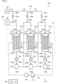
- FIG. 1 is a diagram illustrating a hydrocarbon production apparatus according to a first embodiment.
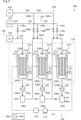
- FIG. 2 is a diagram illustrating a hydrocarbon production apparatus according to the second embodiment.
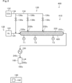
- FIG. 3 is a diagram illustrating a hydrocarbon production apparatus according to a modified example.
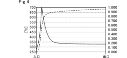
- FIG. 4 is a graph showing the simulation results of the comparative example.
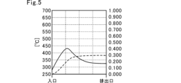
- FIG. 5 is a graph showing the simulation results of the first reactor in the example.
- FIG. 6 is a graph showing the simulation results of the second reactor in the example.
- FIG. 1 is a diagram illustrating a hydrocarbon production apparatus 100 according to a first embodiment.
- the hydrocarbon production apparatus 100 according to the first embodiment includes a reaction device 110, temperature sensors T1, T2, and T3, a hydrogen supply unit 120, a carbon dioxide supply unit 130, a cooler 150, a gas-liquid separator 160, a temperature adjustment unit 170, and a central control unit 180.
- solid arrows indicate the flows of hydrogen (gas), carbon dioxide (gas), hydrocarbon (gas), and water (gas and liquid).
- dashed arrows indicate the flow of a heat medium.
- a synthesis reaction between hydrogen and carbon dioxide takes place to produce hydrocarbons.
- the synthesis reaction between hydrogen and carbon dioxide is an exothermic reaction.
- the synthesis reaction between hydrogen and carbon dioxide is, for example, the reactions shown in the following formulas (1) to (4). 4H 2 + CO 2 ⁇ CH 4 + 2H 2 O...Formula (1) 6H 2 + 2CO 2 ⁇ C 2 H 4 + 4H 2 O...Formula (2) 9H 2 + 3CO 2 ⁇ C 3 H 6 + 6H 2 O...Formula (3) mH2 + nCO2 ⁇ hydrocarbon + 2nH2O ... Equation (4) Methane is produced by the reaction shown in the above formula (1).
- Ethylene is produced by the reaction shown in the above formula (2).
- Propylene is produced by the reaction shown in the above formula (3). Hydrocarbons are produced by the FT (Fischer-Tropsch) synthesis reaction shown in the above formula (4).
- FT Fischer-Tropsch
- a case in which the reaction shown in the above formula (1) is carried out in the reaction device 110 and methane is produced will be taken as an example.
- the reaction device 110 has an inlet 230a for hydrogen and carbon dioxide, an outlet 232c for the gas after the reaction, and one or more carbon dioxide supply ports 230b, 230c provided between the inlet 230a and the outlet 232c.
- the reaction device 110 also contains a catalyst 220.
- a layer of the catalyst 220 (catalyst layer) is formed in the reaction device 110.
- the catalyst 220 is a catalyst that promotes the exothermic reaction between hydrogen and carbon dioxide.
- the catalyst 220 is, for example, a catalyst that promotes the reaction shown in formula (1). In FIG. 1, the catalyst 220 is indicated by cross-hatching.
- the reaction device 110 includes, for example, a plurality of reactors 210 connected in series. Since the reaction device 110 is composed of a plurality of reactors 210 connected in series, the carbon dioxide supply ports 230b, 230c can be easily formed.
- the reactor 210 is, for example, a multi-tube heat exchange type reactor.
- the reactor 210 has a heat medium container 212 and a plurality of reaction tubes 214. A heat medium is supplied to the heat medium container 212 by the temperature adjustment unit 170 described later.
- reaction tubes 214 are provided in the heat medium container 212.
- the reaction tubes 214 contain a catalyst 220.
- a layer of the catalyst 220 (catalyst layer) is formed in the reaction tubes 214.
- the temperature inside the reaction tubes 214 (the temperature of the catalyst layer) is, for example, 200°C or higher and 550°C or lower due to the heat generated by the heat medium passing through the heat medium container 212 and the exothermic reaction proceeding inside the reaction tubes 214.
- the reaction apparatus 110 is composed of three reactors 210, for example, a first reactor 210a, a second reactor 210b, and a third reactor 210c.
- the first reactor 210a, the second reactor 210b, and the third reactor 210c are connected in series in this order.
- the first reactor 210a at the front stage is provided with an inlet 230a and an outlet 232a.
- the inlet 230a is connected to one side of the multiple reaction tubes 214 of the first reactor 210a.
- the outlet 232a is connected to the other side of the multiple reaction tubes 214 of the first reactor 210a.
- the inlet 230a of the first reactor 210a is connected to the hydrogen supply unit 120 and the carbon dioxide supply unit 130 described below.
- the outlet 232a of the first reactor 210a is connected to the supply port 230b of the second reactor 210b via a pipe 240a.
- the second reactor 210b is provided with a supply port 230b and a discharge port 232b.
- the supply port 230b is connected to one side of the multiple reaction tubes 214 of the second reactor 210b.
- the discharge port 232b is connected to the other side of the multiple reaction tubes 214 of the second reactor 210b.
- the discharge port 232b of the second reactor 210b is connected to the supply port 230c of the third reactor 210c at the last stage via a pipe 240b.
- the third reactor 210c is provided with a supply port 230c and an outlet 232c.
- the supply port 230c is connected to one side of the multiple reaction tubes 214 of the third reactor 210c.
- the outlet 232c is connected to the other side of the multiple reaction tubes 214 of the third reactor 210c.
- a pipe 240c is connected to the outlet 232c of the third reactor 210c. The product gas produced in the reaction device 110 and containing 90% or more hydrocarbons is discharged to the outside through the pipe 240c.
- the length of the reaction tube 214 of the reactor 210 increases from the front stage to the rear stage.
- the length of the reaction tube 214 may increase in the order of the first reactor 210a, the second reactor 210b, and the third reactor 210c.
- the distance between the inlet 230a and the supply port 230b that is the shortest distance from the inlet 230a may be shorter than the distance between the supply port 230b and the supply port 230c.
- the distance between the outlet 232c and the supply port 230c that is the shortest distance from the outlet 232c may be longer than the distance between the supply port 230b and the supply port 230c.
- Temperature sensor T1 detects the temperature of the catalyst 220 (catalyst layer) housed in the reaction tube 214 of the first reactor 210a. Temperature sensor T2 detects the temperature of the catalyst 220 (catalyst layer) housed in the reaction tube 214 of the second reactor 210b. Temperature sensor T3 detects the temperature of the catalyst 220 (catalyst layer) housed in the reaction tube 214 of the third reactor 210c.
- the hydrogen supply unit 120 (first hydrogen supply unit) supplies hydrogen into the first reactor 210a through the inlet 230a of the first reactor 210a of the reaction device 110.
- the hydrogen supply unit 120 includes, for example, a blower 122 and a raw material gas supply pipe 124.
- the suction side of the blower 122 is connected to a hydrogen supply source.
- the discharge side of the blower 122 is connected to the raw material gas supply pipe 124.
- the raw material gas supply pipe 124 connects the discharge side of the blower 122 to the inlet 230a of the first reactor 210a of the reaction device 110.
- the carbon dioxide supply unit 130 supplies carbon dioxide to the first reactor 210a, the second reactor 210b, and the third reactor 210c through the inlet 230a of the first reactor 210a, the supply port 230b of the second reactor 210b, and the supply port 230b of the third reactor 210c of the reaction device 110.
- the carbon dioxide supply unit 130 includes, for example, a blower 132, a carbon dioxide supply pipe 134, branch pipes 136a, 136b, and 136c, and flow control valves 138a, 138b, and 138c.
- the suction side of the blower 132 is connected to a carbon dioxide supply source.
- the discharge side of the blower 132 is connected to the carbon dioxide supply pipe 134.
- the branch pipe 136a connects the carbon dioxide supply pipe 134 and the raw gas supply pipe 124.
- the carbon dioxide discharged from the blower 132 is supplied to the first reactor 210a through the carbon dioxide supply pipe 134, the branch pipe 136a, the raw gas supply pipe 124, and the inlet 230a of the first reactor 210a of the reaction device 110.
- the branch pipe 136b connects the carbon dioxide supply pipe 134 and the pipe 240a.
- the carbon dioxide discharged from the blower 132 is supplied to the second reactor 210b through the carbon dioxide supply pipe 134, the branch pipe 136b, the pipe 240a, and the supply port 230b of the second reactor 210b of the reaction device 110.
- the branch pipe 136c connects the carbon dioxide supply pipe 134 and the pipe 240b.
- the carbon dioxide discharged from the blower 132 is supplied to the third reactor 210c through the carbon dioxide supply pipe 134, the branch pipe 136c, the pipe 240b, and the supply port 230c of the third reactor 210c of the reaction device 110.
- Flow rate control valve 138a is provided in branch pipe 136a. Flow rate control valve 138a adjusts the opening of the flow path formed in branch pipe 136a. Flow rate control valve 138b is provided in branch pipe 136b. Flow rate control valve 138b adjusts the opening of the flow path formed in branch pipe 136b. Flow rate control valve 138c is provided in branch pipe 136c. Flow rate control valve 138c adjusts the opening of the flow path formed in branch pipe 136c.
- the opening rates of flow rate control valves 138a, 138b, and 138c are adjusted by flow rate control unit 182, which will be described later. The opening rate adjustment process by flow rate control unit 182 will be described in detail later.
- the cooler 150 cools the gas discharged from the outlets 232a, 232b of at least one of the multiple reactors 210.
- the cooler 150 is, for example, a heat exchanger.
- the hydrocarbon production apparatus 100 has, for example, three coolers 150a, 150b, and 150c.
- the cooler 150a is provided on the pipe 240a.
- the cooler 150a cools the gas discharged from the outlet 232a of the first reactor 210a.
- the gas discharged from the first reactor 210a includes hydrogen, carbon dioxide, methane, and water (gas).
- the cooler 150b is provided on the pipe 240b.
- the cooler 150b cools the gas discharged from the outlet 232b of the second reactor 210b.
- the gas discharged from the second reactor 210b includes hydrogen, carbon dioxide, methane, and water (gas).
- the cooler 150c is provided on the pipe 240c.
- the cooler 150c cools the gas discharged from the outlet 232c of the third reactor 210c.
- the gas discharged from the third reactor 210c includes hydrogen, carbon dioxide, methane, and water (gas).
- the gas-liquid separator 160 separates the mixture of gas and liquid (liquid water) cooled by the cooler 150 into gas and liquid.
- the hydrocarbon production apparatus 100 has, for example, three gas-liquid separators 160a, 160b, and 160c.
- Gas-liquid separator 160a is provided on pipe 240a. Gas-liquid separator 160a separates the mixture of gas and liquid water cooled by cooler 150a into gas and liquid. Gas-liquid separator 160b is provided on pipe 240b. Gas-liquid separator 160b separates the mixture of gas and liquid water cooled by cooler 150b into gas and liquid. Gas-liquid separator 160c is provided on pipe 240c. Gas-liquid separator 160c separates the mixture of gas and liquid water cooled by cooler 150c into gas and liquid.
- the temperature adjustment unit 170 maintains the temperature of the reactor 210 of the reaction device 110 within a predetermined reaction temperature range.
- the reaction temperature range is a temperature range in which the synthesis reaction of hydrogen and carbon dioxide proceeds efficiently and in which deterioration of the catalyst 220 can be suppressed.
- the reaction temperature range is, for example, 200°C or higher and 550°C or lower, and preferably 300°C or higher and 500°C or lower.
- the temperature adjustment unit 170 circulates a heat medium at a predetermined temperature, for example, to the heat medium container 212 of the first reactor 210a, the heat medium container 212 of the second reactor 210b, and the heat medium container 212 of the third reactor 210c.
- the temperature adjustment unit 170 includes, for example, a circulation path 172, a pump 174, and a heating and cooling unit 176.
- the circulation path 172 is a flow path through which the heat medium circulates.
- the circulation path 172 is provided with the pump 174, the heating and cooling unit 176, the heat medium container 212 of the first reactor 210a, the heat medium container 212 of the second reactor 210b, and the heat medium container 212 of the third reactor 210c, in this order.
- the suction side of the pump 174 is connected to the heat medium container 212 of the third reactor 210c.
- the discharge side of the pump 174 is connected to the heating and cooling unit 176.
- the heat medium circulates through the circulation path 172.
- the heating and cooling unit 176 heats or cools the heat medium.
- the central control unit 180 is composed of a semiconductor integrated circuit including a CPU (central processing unit).
- the central control unit 180 reads out programs and parameters for operating the CPU from the ROM.
- the central control unit 180 manages and controls the entire hydrocarbon production apparatus 100 in cooperation with the RAM as a work area and other electronic circuits.
- the central control unit 180 controls the temperature adjustment unit 170 to circulate the heat medium to the first reactor 210a, the second reactor 210b, and the third reactor 210c.
- the central control unit 180 also controls the hydrogen supply unit 120 to supply a predetermined amount of hydrogen to the reaction device 110.
- the central control unit 180 controls the carbon dioxide supply unit 130 to supply a predetermined amount of carbon dioxide to the reaction device 110.
- the central control unit 180 also functions as, for example, a flow rate control unit 182.
- the flow rate control unit 182 controls the flow rate of carbon dioxide supplied to each of the first reactor 210a, the second reactor 210b, and the third reactor 210c by the carbon dioxide supply unit 130 based on, for example, the detection values of the temperature sensors T1, T2, and T3.
- the flow rate control unit 182 controls the flow rate of carbon dioxide supplied to each of the first reactor 210a, the second reactor 210b, and the third reactor 210c by adjusting the opening degree of each of the flow rate adjustment valves 138a, 138b, and 138c.
- the flow control unit 182 adjusts the opening of each of the flow control valves 138a, 138b, and 138c so that the detection value of the temperature sensor T1 (temperature of the first reactor 210a), the detection value of the temperature sensor T2 (temperature of the second reactor 210b), and the detection value of the temperature sensor T3 (temperature of the third reactor 210c) are all within the above reaction temperature range, for example, 200°C or higher and 550°C or lower.
- the flow control unit 182 reduces the opening of the flow control valve 138a.
- the flow control unit 182 increases the opening of the flow control valve 138a.
- the hydrocarbon production apparatus 100 includes a first reactor 210a, a second reactor 210b, a third reactor 210c, a hydrogen supply unit 120 that supplies hydrogen to the first reactor 210a, and a carbon dioxide supply unit 130 that supplies carbon dioxide to the first reactor 210a, the second reactor 210b, and the third reactor 210c.
- the hydrocarbon production apparatus 100 divides and supplies carbon dioxide to each of the multiple reactors 210, making it possible to suppress the rapid progression of the exothermic reaction in the first reactor 210a and to prevent the temperature of the first reactor 210a from rising too high. This allows the hydrocarbon production apparatus 100 to maintain an appropriate temperature inside the reactor 110. Therefore, the hydrocarbon production apparatus 100 makes it possible to prevent deterioration of the catalyst 220 in the reactor 110 due to heat.
- the hydrocarbon production apparatus 100 supplies hydrogen only to the first reactor 210a in the front stage, and splits and supplies carbon dioxide to the first reactor 210a, the second reactor 210b, and the third reactor 210c, so that the amount of carbon dioxide supplied to the first reactor 210a can be reduced compared to the comparative technology.
- the hydrocarbon production apparatus 100 according to this embodiment can supply a greater amount of hydrogen to the first reactor 210a compared to the comparative technology. This makes it possible for the hydrocarbon production apparatus 100 to avoid a situation in which the catalyst 220 in the first reactor 210a is oxidized and deteriorated.
- the hydrocarbon production apparatus 100 divides the carbon dioxide, which has a relatively small flow rate, and supplies it to each reactor 210, and adjusts the flow rate of the carbon dioxide supplied to each reactor 210, thereby easily controlling the temperature of each reactor 210. Furthermore, since the hydrocarbon production apparatus 100 according to this embodiment supplies the entire amount of hydrogen, which has a relatively large flow rate, to the first reactor 210a, the amount of gas that does not contribute to the reaction in the first reactor 210a can be made greater than in the comparative technology. As a result, the hydrocarbon production apparatus 100 according to this embodiment can suppress the increase in reaction heat caused by gas that does not contribute to the reaction more than in the comparative technology.
- the flow rate control unit 182 controls the flow rate of carbon dioxide based on the temperature of the catalyst 220 housed in the reaction device 110. This allows the hydrocarbon production device 100 to keep the temperatures of the first reactor 210a, the second reactor 210b, and the third reactor 210c all within the reaction temperature range. Therefore, the hydrocarbon production device 100 can shorten the start-up time, prevent further thermal deterioration of the catalyst 220, and prevent a decrease in the production efficiency of hydrocarbons.
- the flow control unit 182 adjusts the aperture of the flow control valve 138a so that the stoichiometric ratio between the hydrogen supplied from the hydrogen supply unit 120 to the first reactor 210a and the carbon dioxide supplied from the carbon dioxide supply unit 130 to the first reactor 210a satisfies the above formula (1).
- the flow control unit 182 also adjusts the aperture of the flow control valve 138b so that the stoichiometric ratio between the remaining hydrogen supplied from the first reactor 210a to the second reactor 210b and the carbon dioxide supplied from the carbon dioxide supply unit 130 to the second reactor 210b satisfies the above formula (1).
- the flow control unit 182 also adjusts the aperture of the flow control valve 138c so that the stoichiometric ratio between the remaining hydrogen supplied from the second reactor 210b to the third reactor 210c and the carbon dioxide supplied from the carbon dioxide supply unit 130 to the third reactor 210c satisfies the above formula (1).
- the flow control unit 182 supplies carbon dioxide to the first reactor 210a, the second reactor 210b, and the third reactor 210c in a stoichiometric ratio during the startup process, so that the exothermic reaction shown in the above formula (1) can proceed efficiently in the first reactor 210a, the second reactor 210b, and the third reactor 210c. Therefore, the hydrocarbon production apparatus 100 can quickly heat up the first reactor 210a, the second reactor 210b, and the third reactor 210c.
- the hydrocarbon production apparatus 100 can quickly heat up the first reactor 210a, the second reactor 210b, and the third reactor 210c, making it possible to shorten the start-up time of the first reactor 210a, the second reactor 210b, and the third reactor 210c compared to conventional technology.
- the hydrocarbon production apparatus 100 does not require a start-up heating mechanism for heating the second reactor 210b and the third reactor 210c, making it possible to reduce the cost of the entire apparatus.
- the flow control unit 182 adjusts the apertures of the flow control valves 138a, 138b, and 138c so that the stoichiometric ratio between the hydrogen supplied from the hydrogen supply unit 120 to the first reactor 210a and the total of the carbon dioxide supplied from the carbon dioxide supply unit 130 to the first reactor 210a, the second reactor 210b, and the third reactor 210c satisfies the above formula (1).
- the flow control unit 182 adjusts the apertures of the flow control valves 138a, 138b, and 138c so that the amount of carbon dioxide supplied increases in the order of the first reactor 210a, the second reactor 210b, and the third reactor 210c.
- the flow control unit 182 adjusts the aperture of the flow control valves 138a, 138b so that the amount of carbon dioxide supplied from the carbon dioxide supply unit 130 to the first reactor 210a is less than the amount of carbon dioxide supplied from the carbon dioxide supply unit 130 to the second reactor 210b. Also, for example, the flow control unit 182 adjusts the aperture of the flow control valves 138b, 138c so that the amount of carbon dioxide supplied from the carbon dioxide supply unit 130 to the second reactor 210b is less than the amount of carbon dioxide supplied from the carbon dioxide supply unit 130 to the third reactor 210c.
- the synthesis reaction shown in the above formula (1) can be prevented from progressing rapidly in the first reactor 210a and the second reactor 210b.
- the synthesis reaction shown in formula (1) is an exothermic reaction, by preventing the synthesis reaction shown in formula (1) from progressing rapidly, it is possible to avoid a situation in which the temperature rises too much in the first reactor 210a and the second reactor 210b. Therefore, the hydrocarbon production apparatus 100 can avoid a situation in which the catalyst 220 in the first reactor 210a and the second reactor 210b is deteriorated by heat.
- the hydrocarbon production apparatus 100 does not require a dedicated cooling mechanism for cooling the first reactor 210a and the second reactor 210b, making it possible to reduce the cost of the entire apparatus.
- the hydrogen supply source is a water electrolysis device that performs water electrolysis using renewable energy such as solar power generation
- the amount of hydrogen supplied by the hydrogen supply unit 120 may fluctuate.
- any one or more of the reactors 210 among the first reactor 210a, the second reactor 210b, and the third reactor 210c may fall below the reaction temperature range.
- the temperature of the heat medium circulating through the first reactor 210a, the second reactor 210b, and the third reactor 210c may suddenly fluctuate, or the heat medium may drift.
- any one or more of the reactors 210 among the first reactor 210a, the second reactor 210b, and the third reactor 210c may fall below the reaction temperature range.
- the flow control unit 182 adjusts the opening of the flow control valves 138a, 138b, and 138c so as to increase the amount of carbon dioxide supplied to the reactor 210 in which the temperature of the catalyst 220 falls below the reaction temperature range.
- This allows the hydrocarbon production apparatus 100 to increase the temperature of the reactor 210 in which the temperature of the catalyst 220 falls below the reaction temperature range. Therefore, the hydrocarbon production apparatus 100 can prevent a decrease in the hydrocarbon production efficiency due to a drop in temperature.
- the distance between the inlet 230a and the supply port 230b that is the shortest distance from the inlet 230a may be shorter than the distance between the supply port 230b and the supply port 230c. That is, in the reaction device 110, the distance between the supply port 230b and the supply port 230c may be longer than the distance between the inlet 230a and the supply port 230b that is the shortest distance from the inlet 230a. That is, the length of the reaction tube 214 of the second reactor 210b may be longer than that of the first reactor 210a. This allows the residence time of the gas in the second reactor 210b to be longer than that of the first reactor 210a. Therefore, it is possible to improve the conversion rate of carbon dioxide in the second reactor 210b.
- the conversion rate of carbon dioxide is the ratio at which carbon dioxide is converted to hydrocarbons.
- the distance between the outlet 232c and the supply port 230c which is the shortest distance from the outlet 232c, may be longer than the distance between the supply port 230b and the supply port 230c.
- the length of the reaction tube 214 of the third reactor 210c may be longer than that of the second reactor 210b. This allows the residence time of the gas in the third reactor 210c to be longer than that of the second reactor 210b. Therefore, it is possible to improve the carbon dioxide conversion rate in the third reactor 210c.
- the hydrocarbon production apparatus 100 is equipped with a cooler 150. Because the synthesis reactions of the above formulas (1) to (4) are exothermic reactions, the reactions proceed more easily at low temperatures than at high temperatures (the carbon dioxide conversion rate is higher). Therefore, by providing the hydrocarbon production apparatus 100 with the cooler 150, it becomes possible to further promote the progress of the synthesis reactions of the above formulas (1) to (4) in the second reactor 210b and the third reactor 210c.
- the hydrocarbon production apparatus 100 is equipped with a gas-liquid separator 160.
- a gas-liquid separator 160 In the synthesis reactions of the above formulas (1) to (4), water is produced. For this reason, due to the equilibrium relationship, the conversion rate of carbon dioxide can be increased by removing water from the produced gas. Therefore, by providing the gas-liquid separator 160, the hydrocarbon production apparatus 100 can further promote the progress of the synthesis reactions of the above formulas (1) to (4) in the second reactor 210b and the third reactor 210c.
- FIG. 2 is a diagram illustrating a hydrocarbon production apparatus 300 according to a second embodiment.
- the hydrocarbon production apparatus 300 according to the second embodiment includes a reaction device 110, a hydrogen supply unit 120, a carbon dioxide supply unit 130, a hydrogen supply unit 340, a cooler 150, a gas-liquid separator 160, a temperature adjustment unit 170, and a central control unit 380.
- solid arrows indicate the flow of hydrogen (gas), carbon dioxide (gas), hydrocarbon (gas), and water (gas and liquid).
- dashed arrows indicate the flow of a heat medium. Note that the same reference numerals are used for components that are substantially the same as those in the above-mentioned hydrocarbon production apparatus 300, and description thereof will be omitted.
- the hydrogen supply unit 340 (second hydrogen supply unit) supplies hydrogen into the reaction device 110 through the supply ports 230b and 230c of the reaction device 110.
- the hydrogen supply unit 340 supplies hydrogen into the second reactor 210b through the supply port 230b of the second reactor 210b, and supplies hydrogen into the third reactor 210c through the supply port 230b of the third reactor 210c.
- the hydrogen supply unit 340 includes, for example, a blower 342, a hydrogen supply pipe 344, branch pipes 346b and 346c, and flow control valves 348b and 348c.
- the intake side of the blower 342 is connected to a hydrogen supply source.
- the discharge side of the blower 342 is connected to the hydrogen supply pipe 344.
- the branch pipe 346b connects the hydrogen supply pipe 344 and the pipe 240a.
- the hydrogen discharged from the blower 342 is supplied to the second reactor 210b through the hydrogen supply pipe 344, the branch pipe 346b, the pipe 240a, and the supply port 230b of the second reactor 210b of the reaction device 110.
- the branch pipe 346c connects the hydrogen supply pipe 344 and the pipe 240b.
- the hydrogen discharged from the blower 342 is supplied to the third reactor 210c through the hydrogen supply pipe 344, the branch pipe 346c, the pipe 240b, and the supply port 230c of the third reactor 210c of the reaction device 110.
- Flow rate control valve 348b is provided in branch pipe 346b. Flow rate control valve 348b adjusts the opening degree of the flow path formed in branch pipe 346b. Flow rate control valve 348c is provided in branch pipe 346c. Flow rate control valve 348c adjusts the opening degree of the flow path formed in branch pipe 346c. The opening degrees of flow rate control valves 348b and 348c are adjusted by flow rate control unit 382 described later.
- the central control unit 380 is composed of a semiconductor integrated circuit including a CPU (central processing unit).
- the central control unit 380 reads out programs and parameters for operating the CPU from the ROM.
- the central control unit 380 manages and controls the entire hydrocarbon production apparatus 300 in cooperation with the RAM as a work area and other electronic circuits.
- the central control unit 380 controls the temperature adjustment unit 170 to circulate the heat medium to the first reactor 210a, the second reactor 210b, and the third reactor 210c.
- the central control unit 380 also controls the hydrogen supply unit 120 to supply a predetermined amount of hydrogen to the reaction device 110.
- the central control unit 380 controls the carbon dioxide supply unit 130 to supply a predetermined amount of carbon dioxide to the reaction device 110.
- the central control unit 380 also functions as, for example, a flow control unit 382.
- the flow control unit 382 controls the flow rate of carbon dioxide supplied to the first reactor 210a, the second reactor 210b, and the third reactor 210c by the carbon dioxide supply unit 130 and the flow rate of hydrogen supplied to the first reactor 210a, the second reactor 210b, and the third reactor 210c by the hydrogen supply unit 340, based on, for example, the detection values of the temperature sensors T1, T2, and T3.
- the flow control unit 382 controls the flow rate of carbon dioxide and the flow rate of hydrogen supplied to the first reactor 210a, the second reactor 210b, and the third reactor 210c by adjusting the opening degree of each of the flow control valves 138a, 138b, 138c, 348b, and 348c.
- the flow control unit 382 adjusts the opening of each of the flow control valves 138a, 138b, 138c, 348b, and 348c so that the detection value of the temperature sensor T1 (temperature of the first reactor 210a), the detection value of the temperature sensor T2 (temperature of the second reactor 210b), and the detection value of the temperature sensor T3 (temperature of the third reactor 210c) are all within the reaction temperature range.
- the hydrocarbon production apparatus 300 includes a hydrogen supply unit 340 in addition to a carbon dioxide supply unit 130, and a flow rate control unit 382 controls the flow rate of carbon dioxide supplied to the first reactor 210a, the second reactor 210b, and the third reactor 210c by the carbon dioxide supply unit 130, and the flow rate of hydrogen supplied to the first reactor 210a, the second reactor 210b, and the third reactor 210c by the hydrogen supply unit 340, based on the detection values of the temperature sensors T1, T2, and T3.
- the hydrocarbon production apparatus 300 is able to control the temperatures of the first reactor 210a, the second reactor 210b, and the third reactor 210c with greater precision.
- reaction apparatus 110 includes a plurality of reactors 210.
- reaction apparatus 110 may include only one reactor.
- FIG. 3 is a diagram illustrating a modified hydrocarbon production apparatus 400.
- the modified hydrocarbon production apparatus 400 includes a reaction device 410, a hydrogen supply unit 120, a carbon dioxide supply unit 130, a cooler 150, a gas-liquid separator 160, a temperature adjustment unit 170, and a central control unit 180.
- solid arrows indicate the flows of hydrogen (gas), carbon dioxide (gas), hydrocarbons (gas), and water (gas and liquid). Note that components that are substantially the same as those in the above-described hydrocarbon production apparatus 100 are given the same reference numerals and will not be described.
- the reaction apparatus 410 includes one reactor 420 and temperature sensors T1, T2, and T3.
- the reactor 420 is, for example, an adiabatic reactor.
- the reactor 420 is provided with an inlet 230a, supply ports 230b, 230b, and an outlet 232c, in this order.
- the reactor 420 contains a catalyst 220.
- temperature sensor T1 detects the temperature of the catalyst layer housed between inlet 230a and supply port 230b in reactor 420.
- Temperature sensor T2 detects the temperature of the catalyst layer housed between supply port 230b and supply port 230c in reactor 420.
- Temperature sensor T3 detects the temperature of the catalyst layer housed between supply port 230c and outlet 232c in reactor 420.
- carbon dioxide is divided and supplied to the inlet 230a and the supply ports 230b and 230c, respectively, so that the rapid progress of the exothermic reaction in the reactor 420 can be suppressed, and it is possible to prevent the temperature in the reactor 420 from rising too high.
- This allows the hydrocarbon production apparatus 400 to maintain an appropriate temperature inside the reactor 410. Therefore, the hydrocarbon production apparatus 400 can prevent deterioration of the catalyst 220 in the reactor 410 due to heat.
- Example 2 the temperature of the catalyst layer and the conversion rate of carbon dioxide were simulated when methane was produced using the reaction device 110 equipped with the first reactor 210a and the second reactor 210b.
- hydrogen and carbon dioxide were supplied from the inlet 230a of the first reactor 210a, and carbon dioxide was supplied from the supply port 230b of the second reactor 210b.
- the ratio of hydrogen (moles) supplied from the inlet 230a to the total (moles) of carbon dioxide supplied from the inlet 230a and the supply port 230b was 4:1.
- the ratio of carbon dioxide supplied from the inlet 230a to the carbon dioxide supplied from the supply port 230b was 30:70.
- the temperature of the catalyst layer and the carbon dioxide conversion rate were simulated when methane was produced using a single reactor equipped only with an inlet 230a and an outlet 232c, without a supply port.
- hydrogen and carbon dioxide were supplied from the inlet 230a.
- a simulation was performed for a hydrogen (moles):carbon dioxide (moles) ratio of 4:1.
- FIG. 4 is a graph showing the simulation results of the comparative example.
- FIG. 5 is a graph showing the simulation results of the first reactor 210a in the example.
- FIG. 6 is a graph showing the simulation results of the second reactor 210b in the example.
- the vertical axis on the left side indicates the temperature [°C]
- the vertical axis on the right side indicates the carbon dioxide conversion rate.
- the solid line indicates the temperature of the catalyst layer
- the dashed line indicates the carbon dioxide conversion rate.
- the carbon dioxide conversion rate in the second reactor 210b was comparable to that in the comparative example. This shows that in the embodiment, carbon dioxide can be efficiently converted to methane while suppressing thermal deterioration of the catalyst layer.
- the hydrocarbon production apparatus 100, 300 is provided with temperature sensors T1, T2, T3, and the flow rate control units 182, 382 control the flow rates of carbon dioxide supplied to the first reactor 210a, the second reactor 210b, and the third reactor 210c by the carbon dioxide supply unit 130 based on the detection values of the temperature sensors T1, T2, T3.
- the hydrocarbon production apparatus 100, 300 does not need to be provided with the temperature sensors T1, T2, T3.
- the memory (not shown) of the hydrocarbon production apparatus 100, 300 stores information indicating the relationship between the amount of carbon dioxide supplied to the first reactor 210a and the temperature of the catalyst layer of the first reactor 210a, information indicating the relationship between the amount of carbon dioxide supplied to the second reactor 210b and the temperature of the catalyst layer of the second reactor 210b, and information indicating the relationship between the amount of carbon dioxide supplied to the third reactor 210c and the temperature of the catalyst layer of the third reactor 210c, which are preset by simulation or the like.
- the flow rate control unit 182, 382 refers to the information indicating the relationship between the amount of carbon dioxide supplied to the first reactor 210a and the temperature of the catalyst layer of the first reactor 210a, which is stored in the memory, and adjusts the opening degree of the flow rate control valve 138a so that the catalyst layer of the first reactor 210a is within the reaction temperature range.
- the flow control units 182 and 382 refer to information stored in memory indicating the relationship between the amount of carbon dioxide supplied to the second reactor 210b and the temperature of the catalyst layer of the second reactor 210b, and adjust the opening of the flow control valve 138b so that the catalyst layer of the second reactor 210b is in the reaction temperature range.
- the flow control units 182 and 382 refer to information stored in memory indicating the relationship between the amount of carbon dioxide supplied to the third reactor 210c and the temperature of the catalyst layer of the third reactor 210c, and adjust the opening of the flow control valve 138c so that the catalyst layer of the third reactor 210c is in the reaction temperature range.
- the flow control units 182, 382 may control the flow rate of carbon dioxide supplied by the carbon dioxide supply unit 130 based on the concentration of hydrocarbons contained in the generated gas discharged from the pipe 240c. In other words, the flow control units 182, 382 may adjust the opening of the flow control valves 138a, 138b, 138c based on the concentration of hydrocarbons contained in the generated gas discharged from the pipe 240c. This allows the inside of the reaction device 110 to be at an appropriate temperature.
- the flow control units 182, 382 may also control the flow rate of carbon dioxide to control the temperature of the catalyst layer contained in the reaction device 110.
- the reactor 110 of the hydrocarbon production apparatus 100, 300 has two supply ports 230b, 230c.
- the reactor 110 may have one supply port, or three or more supply ports.
- the distance between the inlet and the supply port with the shortest distance from the inlet may be shorter than the distance between the outlet and the supply port with the shortest distance from the outlet.
- the distance between adjacent supply ports may be longer from the inlet 230a side toward the outlet 232c side.
- the length of the reaction tube 214 may be longer toward the rear stage. This allows the residence time of the gas to be longer from the inlet 230a toward the outlet 232c, making it possible to improve the conversion rate of carbon dioxide.
- the hydrocarbon production apparatus 100, 300 is provided with the coolers 150a, 150b, 150c. However, it is sufficient that the hydrocarbon production apparatus 100, 300 is provided with at least one of the coolers 150a, 150b, 150c. In addition, the hydrocarbon production apparatus 100, 300 does not need to be provided with the cooler 150.
- the hydrocarbon production apparatus 100, 300 is provided with the gas-liquid separators 160a, 160b, 160c. However, it is sufficient that the hydrocarbon production apparatus 100, 300 is provided with at least one of the gas-liquid separators 160a, 160b, 160c. In addition, the hydrocarbon production apparatus 100, 300 does not need to be provided with the gas-liquid separator 160.
- the reactor 210 is a multi-tube, heat exchange type reactor.
- the reactor 210 may be an adiabatic reactor.
- the reactor 420 is an adiabatic reactor.
- the reactor 420 may be a multi-tube, heat exchange type reactor.
- the gas supplied to the reaction device 110 may be replaced with carbon monoxide instead of carbon dioxide.
- carbon monoxide is more reactive with hydrogen than carbon dioxide, and the temperature of the reaction device 110 can be increased quickly during the startup process. Therefore, by replacing the gas supplied to the reaction device 110 from carbon dioxide to carbon monoxide, the startup time can be further shortened.
- carbon monoxide may be supplied to the reaction device 110 in addition to hydrogen and carbon dioxide.
- carbon monoxide is more reactive with hydrogen than carbon dioxide, and the temperature of the reaction device 110 can be increased quickly during the startup process. Therefore, by supplying carbon monoxide mainly to the reaction device 110 during the startup process and then supplying carbon dioxide after the temperature of the reaction device 110 has been increased, it is possible to react carbon dioxide stably and continuously.
- gases with different combinations of carbon dioxide and carbon monoxide may be supplied to each of the multiple reactors 210.
- gases with different combinations of carbon dioxide and carbon monoxide carbon dioxide only, carbon monoxide only, mixed gas of carbon dioxide and carbon monoxide
- a synthesis reaction between hydrogen and carbon monoxide takes place in the reaction device 110 to produce hydrocarbons.
- the synthesis reaction between hydrogen and carbon monoxide is an exothermic reaction.
- the synthesis reaction between hydrogen and carbon monoxide is, for example, the reactions shown in the following formulas (5) to (8). 3H 2 + CO ⁇ CH 4 + H 2 O...Formula (5) 4H 2 + 2CO ⁇ C 2 H 4 + 2H 2 O...Formula (6) 6H 2 + 3CO ⁇ C 3 H 6 + 3H 2 O...Formula (7) mH2 + nCO ⁇ hydrocarbon + nH2O ... formula (8)
- This disclosure can contribute, for example, to Sustainable Development Goal (SDG) Goal 7: “Ensure access to affordable, reliable, sustainable and modern energy” and Goal 13: “Take urgent action to combat climate change and its impacts.”
- SDG Sustainable Development Goal
- Hydrocarbon production equipment 110 Reactor 120: Hydrogen supply unit 130: Carbon dioxide supply unit 150: Cooler 150a: Cooler 150b: Cooler 182: Flow control unit 210: Reactor 210a: First reactor 210b: Second reactor 210c: Third reactor 220: Catalyst 230a: Inlet 230b: Supply port 230c: Supply port 232a: Outlet 232b: Outlet 232c: Outlet 300: Hydrocarbon production equipment 340: Hydrogen supply unit 382: Flow control unit 400: Hydrocarbon production equipment 410: Reactor 420: Reactor
Landscapes
- Chemical & Material Sciences (AREA)
- Organic Chemistry (AREA)
- Engineering & Computer Science (AREA)
- Oil, Petroleum & Natural Gas (AREA)
- Chemical Kinetics & Catalysis (AREA)
- General Chemical & Material Sciences (AREA)
- Organic Low-Molecular-Weight Compounds And Preparation Thereof (AREA)
Priority Applications (2)
| Application Number | Priority Date | Filing Date | Title |
|---|---|---|---|
| JP2025560922A JPWO2025115498A1 (cg-RX-API-DMAC7.html) | 2023-11-27 | 2024-10-30 | |
| DE112024004085.3T DE112024004085T5 (de) | 2023-11-27 | 2024-10-30 | Kohlenwasserstoffproduktionsvorrichtung |
Applications Claiming Priority (2)
| Application Number | Priority Date | Filing Date | Title |
|---|---|---|---|
| JP2023199655 | 2023-11-27 | ||
| JP2023-199655 | 2023-11-27 |
Publications (1)
| Publication Number | Publication Date |
|---|---|
| WO2025115498A1 true WO2025115498A1 (ja) | 2025-06-05 |
Family
ID=95897669
Family Applications (1)
| Application Number | Title | Priority Date | Filing Date |
|---|---|---|---|
| PCT/JP2024/038631 Pending WO2025115498A1 (ja) | 2023-11-27 | 2024-10-30 | 炭化水素製造装置 |
Country Status (3)
| Country | Link |
|---|---|
| JP (1) | JPWO2025115498A1 (cg-RX-API-DMAC7.html) |
| DE (1) | DE112024004085T5 (cg-RX-API-DMAC7.html) |
| WO (1) | WO2025115498A1 (cg-RX-API-DMAC7.html) |
Citations (4)
| Publication number | Priority date | Publication date | Assignee | Title |
|---|---|---|---|---|
| JPS586303A (ja) * | 1981-06-03 | 1983-01-13 | ケルンフオルシユングスアンラ−ゲ・ユ−リツヒ・ゲゼルシヤフト・ミト・ベシユレンクテル・ハフツング | 一酸化炭素、二酸化炭素および水素を含んでいて接触的にメタン化可能な合成ガスとの熱交換で過熱された蒸気を発生させるための方法およびこの方法を実施するためのプラント |
| JP2013136538A (ja) * | 2011-12-28 | 2013-07-11 | Hitachi Zosen Corp | メタネーション反応装置 |
| JP2014198789A (ja) * | 2013-03-29 | 2014-10-23 | 大阪瓦斯株式会社 | メタンリッチガス製造システム |
| JP2019142808A (ja) * | 2018-02-20 | 2019-08-29 | 株式会社豊田中央研究所 | メタン製造装置、および、メタン製造方法 |
Family Cites Families (1)
| Publication number | Priority date | Publication date | Assignee | Title |
|---|---|---|---|---|
| JP2021116294A (ja) | 2020-01-24 | 2021-08-10 | 株式会社日立製作所 | 回収二酸化炭素の有効利用システム、回収二酸化炭素の利用方法、回収二酸化炭素の有効利用システムの制御方法、及び表示装置 |
-
2024
- 2024-10-30 JP JP2025560922A patent/JPWO2025115498A1/ja active Pending
- 2024-10-30 WO PCT/JP2024/038631 patent/WO2025115498A1/ja active Pending
- 2024-10-30 DE DE112024004085.3T patent/DE112024004085T5/de active Pending
Patent Citations (4)
| Publication number | Priority date | Publication date | Assignee | Title |
|---|---|---|---|---|
| JPS586303A (ja) * | 1981-06-03 | 1983-01-13 | ケルンフオルシユングスアンラ−ゲ・ユ−リツヒ・ゲゼルシヤフト・ミト・ベシユレンクテル・ハフツング | 一酸化炭素、二酸化炭素および水素を含んでいて接触的にメタン化可能な合成ガスとの熱交換で過熱された蒸気を発生させるための方法およびこの方法を実施するためのプラント |
| JP2013136538A (ja) * | 2011-12-28 | 2013-07-11 | Hitachi Zosen Corp | メタネーション反応装置 |
| JP2014198789A (ja) * | 2013-03-29 | 2014-10-23 | 大阪瓦斯株式会社 | メタンリッチガス製造システム |
| JP2019142808A (ja) * | 2018-02-20 | 2019-08-29 | 株式会社豊田中央研究所 | メタン製造装置、および、メタン製造方法 |
Also Published As
| Publication number | Publication date |
|---|---|
| DE112024004085T5 (de) | 2026-07-23 |
| JPWO2025115498A1 (cg-RX-API-DMAC7.html) | 2025-06-05 |
Similar Documents
| Publication | Publication Date | Title |
|---|---|---|
| US10252963B2 (en) | Method for producing methanol and apparatus for producing methanol | |
| US10556849B2 (en) | Method for producing methanol and apparatus for producing methanol | |
| EP1465834B1 (en) | Process for the production of hydrocarbons | |
| CN103068727B (zh) | 硫化氢合成反应器、硫化氢制造装置、硫氢化钠制造装置及其方法 | |
| RU2495914C2 (ru) | Устройства и способы обработки водорода и монооксида углерода | |
| EP2464598B1 (en) | Combined reforming process for methanol production | |
| BRPI0610246A2 (pt) | processo para sintetizar metanol | |
| CN113784940B (zh) | 用于合成甲醇的工艺 | |
| AU2002367448A1 (en) | Process for the production of hydrocarbons | |
| US20250313463A1 (en) | Systems and methods for producing hydrogen with integrated capture of carbon dioxide | |
| WO2017121978A1 (en) | Methanol process | |
| JP5813762B2 (ja) | 代替天然ガスの製造のためのプロセス | |
| CN104284859A (zh) | 以天然气为原料的制氨装置的改进方法 | |
| JP6207835B2 (ja) | シフト反応システム | |
| WO2019008317A1 (en) | PROCESS FOR THE SYNTHESIS OF METHANOL | |
| JP2023166900A (ja) | 発電システム | |
| ES3057947T3 (en) | Method for producing higher hydrocarbons with low carbon footprint | |
| US20250178991A1 (en) | Method for producing methanol and apparatus for producing methanol | |
| JP2018154722A (ja) | 反応装置及びガス製造設備 | |
| JP2809561B2 (ja) | リン酸型燃料電池発電装置 | |
| TW202506271A (zh) | 生成裝置 | |
| TWI522172B (zh) | 製備替代天然氣之方法 | |
| JP2007119271A (ja) | 水素製造装置 |
Legal Events
| Date | Code | Title | Description |
|---|---|---|---|
| 121 | Ep: the epo has been informed by wipo that ep was designated in this application |
Ref document number: 24897187 Country of ref document: EP Kind code of ref document: A1 |
|
| ENP | Entry into the national phase |
Ref document number: 2025560922 Country of ref document: JP Kind code of ref document: A |
|
| WWE | Wipo information: entry into national phase |
Ref document number: 112024004085 Country of ref document: DE |
|
| WWP | Wipo information: published in national office |
Ref document number: 112024004085 Country of ref document: DE |