WO2025115484A1 - ポリシリコンロッドの製造方法 - Google Patents
ポリシリコンロッドの製造方法 Download PDFInfo
- Publication number
- WO2025115484A1 WO2025115484A1 PCT/JP2024/038264 JP2024038264W WO2025115484A1 WO 2025115484 A1 WO2025115484 A1 WO 2025115484A1 JP 2024038264 W JP2024038264 W JP 2024038264W WO 2025115484 A1 WO2025115484 A1 WO 2025115484A1
- Authority
- WO
- WIPO (PCT)
- Prior art keywords
- polysilicon
- polysilicon rod
- period
- gas
- growth
- Prior art date
- Legal status (The legal status is an assumption and is not a legal conclusion. Google has not performed a legal analysis and makes no representation as to the accuracy of the status listed.)
- Pending
Links
Images


Classifications
-
- C—CHEMISTRY; METALLURGY
- C01—INORGANIC CHEMISTRY
- C01B—NON-METALLIC ELEMENTS; COMPOUNDS THEREOF; METALLOIDS OR COMPOUNDS THEREOF NOT COVERED BY SUBCLASS C01C
- C01B33/00—Silicon; Compounds thereof
- C01B33/02—Silicon
- C01B33/021—Preparation
- C01B33/027—Preparation by decomposition or reduction of gaseous or vaporised silicon compounds other than silica or silica-containing material
- C01B33/035—Preparation by decomposition or reduction of gaseous or vaporised silicon compounds other than silica or silica-containing material by decomposition or reduction of gaseous or vaporised silicon compounds in the presence of heated filaments of silicon, carbon or a refractory metal, e.g. tantalum or tungsten, or in the presence of heated silicon rods on which the formed silicon is deposited, a silicon rod being obtained, e.g. Siemens process
-
- C—CHEMISTRY; METALLURGY
- C30—CRYSTAL GROWTH
- C30B—SINGLE-CRYSTAL GROWTH; UNIDIRECTIONAL SOLIDIFICATION OF EUTECTIC MATERIAL OR UNIDIRECTIONAL DEMIXING OF EUTECTOID MATERIAL; REFINING BY ZONE-MELTING OF MATERIAL; PRODUCTION OF A HOMOGENEOUS POLYCRYSTALLINE MATERIAL WITH DEFINED STRUCTURE; SINGLE CRYSTALS OR HOMOGENEOUS POLYCRYSTALLINE MATERIAL WITH DEFINED STRUCTURE; AFTER-TREATMENT OF SINGLE CRYSTALS OR A HOMOGENEOUS POLYCRYSTALLINE MATERIAL WITH DEFINED STRUCTURE; APPARATUS THEREFOR
- C30B29/00—Single crystals or homogeneous polycrystalline material with defined structure characterised by the material or by their shape
- C30B29/02—Elements
- C30B29/06—Silicon
Definitions
- the present invention relates to a method for manufacturing polysilicon rods.
- Patent Document 1 discloses a method for producing polysilicon rods in which the chlorosilane flow rate is set to 460 kg of chlorosilane per m2 of silicon surface per hour (kg/(h ⁇ m2 )) within 15 hours from the start of deposition and maintained constant for the remaining required charging time.
- Patent Document 2 discloses a method for producing polysilicon rods in which the amount of source gas is maintained at a constant flow rate in the initial stage of the deposition reaction, and then the flow rate is gradually increased until the maximum flow rate is 3 to 6 times the initial flow rate.
- polysilicon rods deposited early in the growth period generally have low resistivity. Also, at the beginning of the growth period, the diameter of the polysilicon rod is small, and depending on the amount of mixed gas fed into the reactor, the polysilicon rod may shake and collapse.
- One aspect of the present invention aims to improve the resistivity of polysilicon rods deposited early in the growth period while preventing the polysilicon rods from collapsing early in the growth period.
- one aspect of the present invention is a method for producing a polysilicon rod, which is a method for producing a polysilicon rod in which a raw material gas containing chlorosilanes is supplied to a silicon core wire that is set upright inside a reactor and heated by electrical current, thereby precipitating polysilicon on the surface of the silicon core wire and growing it into a polysilicon rod having a diameter of 80 mm or more.
- the raw material gas is fed into the reactor so that the number of gas exchanges, which is the amount of raw material gas fed into the reactor relative to the volume of the reactor, during the period from the start of polysilicon precipitation on the surface of the silicon core wire to the start of growth of the polysilicon rod, from the time when polysilicon starts to be precipitated on the surface of the silicon core wire until one hour has elapsed, is 8 times or more and less than 35 times.
- 1 is a schematic diagram showing an apparatus for manufacturing a polysilicon rod according to a first embodiment of the present invention.
- 1 is a graph showing an example of the diameter of a polysilicon rod during deposition versus deposition time.
- 1 is a graph showing the relationship between deposition time and input gas amount for an example of the present invention and a comparative example.
- 1 is a graph showing the relationship between deposition time and the number of gas exchanges for examples of the present invention and comparative examples.
- 1 is a graph showing measurement results of resistivity values of polysilicon rods according to an embodiment of the present invention and a comparative example.
- the method for manufacturing polysilicon rods S1 according to the present invention prevents the collapse of polysilicon rods S1 during the growth start period T1 and improves the resistivity of the precipitated polysilicon rods S1 by setting the number of gas exchanges in the reactor 10 to a number that the inventors discovered through intensive research.
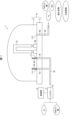
- FIG. 1 is a schematic diagram showing an apparatus 1 for manufacturing a polysilicon rod S1 according to the embodiment 1 of the present invention.
- the apparatus 1 for manufacturing a polysilicon rod S1 includes a control unit 2, a mixer 3, a reactor 10, a supply pipe 20, a supply nozzle 40, an electrode 50, and a discharge pipe 60.
- the diameter of the supply nozzle 40 and the number of supply nozzles 40 installed in the reactor 10 are not particularly limited, but as an example, the diameter of the supply nozzle 40 may be 14 ⁇ or more and 18 ⁇ or less, and the number of supply nozzles 40 may be 10 to 30.
- the reactor 10 is composed of a bottom 11 on which the polysilicon rod S1 is placed, and a bell-jar-shaped lid 12 detachably connected to the bottom 11.
- the reactor 10 contains a source gas G1 for silicon deposition with the lid 12 connected to the bottom 11.
- the source gas G1 is a mixed gas, and chlorosilanes and hydrogen (H 2 ) are mixed by a mixer 3 and fed into the reactor 10.
- the chlorosilanes are, for example, gaseous monochlorosilane (SiH 3 Cl), dichlorosilane (SiH 2 Cl 2 ), trichlorosilane (SiHCl 3 ), and tetrachlorosilane (SiCl 4 ), or a mixture thereof.
- the bottom 11 is formed with an inlet 111 for allowing the raw material gas G1 to flow into the reactor 10, and an outlet 112 for discharging the exhaust gas after the reaction in the reactor 10.
- a through hole H1 that penetrates the bottom 11 extends from the inlet 111.
- a through hole H2 that penetrates the bottom 11 extends from the outlet 112.
- two inlets 111 and one outlet 112 are formed in the bottom 11, but the number of inlets 111 and outlets 112 formed in the bottom 11 is not particularly limited.
- the supply pipe 20 is connected to the end of the through hole H1 opposite the inside of the reactor 10, and supplies the raw material gas G1 to the through hole H1.
- the supply nozzle 40 is a nozzle that protrudes from the inlet 111 into the reactor 10.
- the supply nozzle 40 is provided at the bottom 11 to allow the raw material gas G1 flowing in from the inlet 111 to reach the upper part of the reactor 10 and to grow the polysilicon rod S1 uniformly.
- the height of the tip of the supply nozzle 40 is higher than the top of the electrode 50 so that the raw material gas G1 does not directly hit the vicinity of the electrode 50. By adjusting the gas linear velocity at the tip of the supply nozzle 40, it is possible to prevent the polysilicon rod S1 from being easily broken.
- the supply nozzle 40 is preferably made of a material that is highly resistant to corrosion by the raw material gas G1, for example, carbon.
- the electrodes 50 are members that electrically connect a power source (not shown) and the silicon core wire.
- the deposition temperature of polysilicon is approximately 600°C or higher. From the viewpoint of rapidly depositing polysilicon on the silicon core wire, the silicon core wire is electrically heated so that the silicon core wire is maintained at a temperature of approximately 900 to 1000°C.
- At least one pair of electrodes 50 is provided on the bottom 11. The number of electrodes 50 is determined according to the number of silicon core wires to be installed inside the reactor 10.
- the exhaust pipe 60 is a pipe for exhausting gas formed in the silicon deposition process to the outside of the reactor 10.
- the exhaust pipe 60 extends between the outside of the reactor 10 and the end of the through hole H2 opposite the exhaust port 112.
- the gas exhausted from the silicon deposition process includes chlorosilanes, hydrogen (H 2 ), hydrogen chloride (HCl), by-products, and pollutants.
- the gas formed and exhausted in the silicon deposition process is collected and treated.
- the control unit 2 controls the supply of raw material gas G1 to the reaction furnace 10.
- the control unit 2 controls the supply of raw material gas G1 to the reaction furnace 10 based on the deposition time, the diameter of the polysilicon rod S1, the gas linear velocity at the tip of the supply nozzle 40, etc.
- the functions of the control unit 2 may be realized by a CPU (Central Processing Unit) executing a program stored in a memory unit (not shown).
- the method for producing polysilicon rod S1 of the present application includes a step of introducing raw material gas G1 containing chlorosilanes into a silicon core wire that is erected inside a reaction furnace 10 and heated by electrical current, thereby precipitating polysilicon on the surface of the silicon core wire and growing it into a polysilicon rod S1 having a diameter of 80 mm or more.
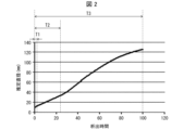
- Figure 2 is a graph showing an example of the diameter of the polysilicon rod S1 during precipitation against each precipitation time.
- the diameter of the polysilicon rod S1 is 80 mm or more, and preferably 90 to 180 mm.
- the growth period is generally 50 hours or more, and preferably 60 to 150 hours.
- the polysilicon rod S1 is precipitated over approximately 100 hours until the diameter reaches approximately 130 mm.
- the time from the start of precipitation of the polysilicon rod S1 to the completion of precipitation (0 hours to 100 hours in Figure 2) will be explained as the growth period T3 (total growth period).
- the "diameter of polysilicon rod S1" refers to the diameter when “polysilicon has been precipitated on the core wire," and the diameter of polysilicon rod S1 includes the core wire. This diameter is obtained by measuring the distance between the right and left ends of polysilicon rod S1 with a distance measuring device (not shown) installed outside reactor 10 through a viewing window (not shown) for observing the inside of reactor 10 installed on the side of bell jar-shaped lid 12.
- the reactor 10 is filled with high-purity gases such as hydrogen or nitrogen, and (2) when production of polysilicon rods S1 begins, the air inside the reactor 10 is replaced with these high-purity gases or raw material gases for purification before the deposition of polysilicon is carried out.
- high-purity gases such as hydrogen or nitrogen
- the diameter of the polysilicon rod S1 is small, and depending on the amount of raw material gas G1 fed into the reaction furnace 10, the polysilicon rod S1 may shake and collapse.
- the polysilicon core wire usually has a diameter of 5 to 15 mm, and when the growth start period T1 has elapsed, the diameter of the polysilicon rod S1 is 6 to 18 mm.
- the inventors have discovered that by limiting the number of gas exchanges in the reactor 10 during the growth start period T1 to between 8 and 35 times, and preferably between 10 and 30 times, it is possible to prevent the polysilicon rods S1 from collapsing during the growth start period T1 and to improve the resistivity of the precipitated polysilicon rods S1.
- the number of gas exchanges during the growth start period T1 is typically less than eight times, but the inventors have discovered that by increasing the number of gas exchanges to eight or more times, it is possible to properly discharge contaminants generated from the reaction furnace 10. This makes it possible to significantly improve the resistivity of the polysilicon rods S1 precipitated during the growth start period T1.
- the productivity of the polysilicon rod S1 also improves. Note that if the number of gas exchanges during the growth start period T1 is 35 or more, the rate at which the polysilicon rod S1 collapses increases, and productivity decreases.
- the number of gas exchanges is the amount of raw material gas G1 fed into the reactor 10 relative to the internal volume of the reactor 10 per hour, and is calculated by (amount of raw material gas G1 fed into the reactor 10)/(internal volume of the reactor 10), and the unit is times/h.
- the linear velocity of the source gas G1 fed into the reaction furnace 10 per supply nozzle 40 is preferably 40 Nm3/(s ⁇ m2 ) or less. This can further enhance the effect of preventing the collapse of the polysilicon rod S1.
- the linear velocity of the source gas G1 per supply nozzle 40 is more preferably 35 Nm3 /(s ⁇ m2 ) or less.
- the lower limit of the linear velocity is appropriately determined depending on the diameter of the supply nozzle 40.
- the lower limit of the linear velocity is appropriately determined in the range of 5.0 Nm3 /(s ⁇ m2 ) to 20.0 Nm3 /(s ⁇ m2 ).
- the “linear velocity” is the linear velocity of gas at the tip of the supply nozzle 40, calculated by "amount of gas input / (cross-sectional area of nozzle x number of nozzles)".
- the source gas G1 is fed into the reaction furnace 10 even after the growth start period T1 during the growth period T3 until the polysilicon rod S1 grows to a desired diameter of 80 mm or more.
- the amount of the source gas G1 fed is generally increased after the growth start period T1 until the deposition of polysilicon is completed.
- the maximum number of gas exchanges per hour is preferably 80 times or more and 100 times or less.
- the amount of source gas G1 input after the growth start period T1 may temporarily be maintained at the same amount as the amount input during the arbitrary period TE-1, or may be reduced from the amount input during the arbitrary period TE-1, depending on the time that has passed since the start of precipitation.
- This decrease in resistivity is particularly likely to occur during the initial growth period T2 (see Figure 2) that follows the growth start period T1 of the polysilicon rod S1 and lasts until its diameter reaches 30 mm.
- the raw material gas G1 into the reaction furnace 10 in such a manner that (1) the rate of increase in the number of gas exchanges per hour during the initial growth period T2 is within the range of 0.6 to 5.0, and (2) the number of gas exchanges has increased to 30 to 50 times in the hour before the diameter of the polysilicon rod S1 reaches 30 mm.
- the rate of increase in the number of gas exchanges per hour is calculated as "(number of gas exchanges in arbitrary period TE)/(number of gas exchanges in arbitrary period TE-1)."
- gas exchange is performed within the above-mentioned range during the initial growth period T2, it is possible to prevent collapse of the polysilicon rod S1 and keep the resistivity low during the initial growth period T2 following the growth start period T1, in which the number of gas exchanges is 8 times or more and less than 35 times.
- gas exchange is performed with the increase ratio of the number of gas exchanges in the range of 0.6 to 5.0, more preferably in the range of 0.7 to 3.5, and particularly preferably in the range of 0.8 to 3.4.
- the number of gas exchanges in the initial growth period T2 can be reduced relative to the number of gas exchanges in the arbitrary period TE-1 if the increase factor is 0.6 or more.
- such a reduction period should be temporary, and in the hour before the diameter of the polysilicon rod S1 reaches 30 mm, the number of gas exchanges should be increased to 30 to 50 times, more preferably 35 to 45 times.
- the time from when the deposition of polysilicon on the silicon core surface starts to when the end of the initial growth period T2 is reached, in other words, from when the deposition of polysilicon starts to when the diameter of the polysilicon rod S1 reaches 30 mm, is typically 10 to 30 hours.
- the linear velocity of the source gas G1 fed into the reaction furnace 10 per supply nozzle 40 is preferably 15 Nm3/(s ⁇ m2 ) or more and 150 Nm3 /(s ⁇ m2 ) or less. This can further enhance the effect of preventing the collapse of the polysilicon rods S1.
- the linear velocity of the source gas G1 per supply nozzle is more preferably 20 Nm3 /(s ⁇ m2 ) or more and 120 Nm3 /(s ⁇ m2 ) or less.
- Example 1 of the present invention will be described with reference to Fig. 3 to Fig. 5.
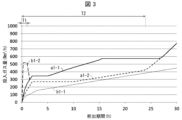
- Fig. 3 is a graph showing the relationship between deposition time and the amount of gas input for the examples of the present invention and the comparative examples. More specifically, Fig. 3 is a graph showing the amount of gas input to the reaction furnace 10 for each hour that has elapsed since the start of deposition.
- Figure 4 is a graph showing the relationship between deposition time and the number of gas exchanges for the examples of the present invention and the comparative examples. More specifically, Figure 4 is a graph showing the number of gas exchanges per hour after the start of deposition.
- Figure 5 is a graph showing the measurement results of the resistivity value of polysilicon rod S1 for the examples of the present invention and the comparative examples. Note that in Figures 3 to 5, a1-1 shows the results for Example 1, and a1-2, b1-1, and b1-2 show the results for Example 2, Comparative Example 1, and Comparative Example 2, respectively, which will be described later.
- Example 1 polysilicon rods S1 were manufactured using the manufacturing apparatus 1 shown in FIG. 1.
- the reactor 10 is capable of erecting 10 polycrystalline silicon rods (five pairs of inverted U-shaped polysilicon rods S1), and in Example 1, five pairs of inverted U-shaped silicon core wires with a height of 2000 mm were erected on the bottom 11 of the reactor 10.
- Each silicon core wire in the reactor 10 was heated by applying electricity until the temperature reached approximately 1000°C, and the source gas G1, a mixture of trichlorosilane and hydrogen, was fed from the supply nozzle 40 to carry out a silicon deposition reaction by the Siemens method for 100 hours.
- the source gas G1 a mixture of trichlorosilane and hydrogen
- the diameter of the polysilicon rod S1 grew, and a polysilicon rod S1 with a diameter of 130 mm was obtained.
- the above diameter is the average of the ten polysilicon rods S1 produced, and in this example, the physical properties of the polysilicon rods S1 thereafter were also evaluated based on the average of the ten rods.
- the source gas G1 was fed into the reaction furnace 10 at a gas input rate of 243 Nm 3 /h as shown by a1-1 in FIG.
- the number of gas exchanges during the growth initiation period T1 was 19, as shown by a1-1 in Fig. 4.
- the linear velocity of the source gas G1 fed into the reaction furnace 10 per the supply nozzle 40 was 30.9 Nm3 /(s ⁇ m2 ).
- raw material gas G1 was fed into the reaction furnace 10 with the amount of gas fed as shown in a1-1 of Figure 3 and the number of gas exchanges as shown in Figure 4.
- the time elapsed from the start of deposition until the diameter of the polysilicon rod S1 reached 30 mm was 21 hours.
- the rate of increase in the number of gas exchanges per hour was in the range of 0.9 to 2.0.
- the number of gas exchanges in the hour before the diameter of the polysilicon rod S1 reached 30 mm increased to 45 times.
- the linear velocity of the source gas G1 fed into the reaction furnace 10 per the supply nozzle 40 was in the range of 30.9 to 72.7 Nm 3 /(s ⁇ m 2 ). Even during this initial growth period T2, not a single polysilicon rod S1 collapsed.
- the number of gas exchanges was gradually increased to a maximum value of 95 times at 42 hours from the start of precipitation, and thereafter, the raw material gas G1 was introduced into the reaction furnace 10 with the increase factor of the number of gas exchanges per hour being in the range of 0.0 to 1.5. Furthermore, during the final hour at the end of growth, the number of gas exchanges was set to 0 times. As described above, growth was terminated when 100 hours had elapsed from the start of precipitation, and a polysilicon rod S1 with a diameter of approximately 130 mm was obtained.
- a core rod with a diameter of 19 mm was hollowed out from the obtained polysilicon rod S1 in a direction perpendicular to the longitudinal direction of the rod S1 and including the core wire, and the resistivity of the core rod in the longitudinal direction was measured to obtain the resistivity of the polysilicon rod S1 in the radial direction.
- the result is shown as a1-1 in Figure 5.
- "Core wire + 2 cm” indicates a state in which polysilicon has precipitated around the core wire to a thickness of about 1 cm (i.e., a diameter 2 cm larger than the diameter of the core wire).
- the resistivity value Xa1-1 of the polysilicon rod S1 with diameter X at the end of the growth start period T1, one hour after the start of polysilicon precipitation was a high value of approximately 1700 ( ⁇ cm).
- Comparative Example 1 Comparative Example 1 of the present invention will be described with reference to Fig. 3 to Fig. 5.
- the polysilicon rod S1 was manufactured in the same manner as in Example 1, except that the amount of raw material gas G1 fed in the growth start period T1 and the initial growth period T2 was changed as follows.
- Comparative Example 1 is a method for manufacturing the polysilicon rod S1 in accordance with the amount of gas fed that is generally used in the past.
- raw material gas G1 was fed into the reaction furnace 10 at the gas feed rate shown in b1-1 of FIG. 3 and the number of gas exchanges shown in FIG. 4.
- the time elapsed from the start of deposition until the diameter of the polysilicon rod S1 reached 30 mm was 21 hours.
- the rate of increase in the number of gas exchanges per hour was in the range of 0.9 to 1.6.
- the number of gas exchanges in the hour before the diameter of the polysilicon rod S1 reached 30 mm increased to 27 times.
- the linear velocity of the source gas G1 fed into the reaction furnace 10 per the supply nozzle 40 was in the range of 9.7 to 37.8 Nm 3 /(s ⁇ m 2 ).
- Example 1 a core rod was hollowed out from the obtained polysilicon rod S1, and its resistivity in the longitudinal direction was determined, and shown as b1-1 in Figure 5.
- the resistivity value Xb1-1 of the polysilicon rod S1 of diameter X at the end of the growth start period T1 was approximately 480 ( ⁇ cm), a value approximately 28% lower than in Example 1.
- the resistivity value Yb1-1 of the polysilicon rod S1 at the end of the initial growth period T2 when the diameter of the polysilicon rod S1 reached 30 mm (diameter Y), was approximately 980 ( ⁇ cm), a value approximately 27% lower than in Example 1.
- Comparative Example 2 (Comparative Example 2) 3 to 5, a description will be given of Comparative Example 2 of the present invention.
- a polysilicon rod S1 was manufactured in the same manner as in Example 1, except that the input amount of the source gas G1 during the growth start period T1 was changed as follows:
- Example 2 of the present invention will be described with reference to Fig. 3 to Fig. 5.
- a polysilicon rod S1 was manufactured in the same manner as in Example 1, except that the input amount of the source gas G1 in the growth start period T1 and the initial growth period T2 was changed as follows.
- Example 2 the amount of gas input during the growth initiation period T1 was reduced to 162 Nm 3 /h as shown in a1-2 of Fig. 3, and the number of gas exchanges during the growth initiation period T1 was reduced to 13 times as shown in a1-2 of Fig. 4.
- the linear velocity of the source gas G1 input into the reaction furnace 10 per supply nozzle 40 was 20.6 Nm 3 /(s ⁇ m 2 ).
- raw material gas G1 was fed into the reaction furnace 10 at the gas feed rate shown in a1-2 of FIG. 3 and the number of gas exchanges shown in FIG. 4.
- the time elapsed from the start of deposition until the diameter of the polysilicon rod S1 reached 30 mm was 21 hours.
- the rate of increase in the number of gas exchanges per hour was in the range of 0.8 to 2.2.
- the number of gas exchanges in the hour before the diameter of the polysilicon rod S1 reached 30 mm increased to 30.
- the linear velocity of the source gas G1 fed into the reaction furnace 10 per the supply nozzle 40 was in the range of 20.6 to 48.7 Nm 3 /(s ⁇ m 2 ).
- Example 2 As in Example 1, a core rod was hollowed out from the obtained polysilicon rod S1, and the resistivity in the longitudinal direction was determined, which is shown as a1-2 in Figure 5.
- the resistivity value Xa1-2 of the polysilicon rod S1 of diameter X at the end of the growth start period T1 was a high value of approximately 940 ( ⁇ cm).
- the resistivity value Ya1-2 of the polysilicon rod S1 at the end of the initial growth period T2 when the diameter of the polysilicon rod S1 reached 30 mm (diameter Y), was approximately 2050 ( ⁇ cm), and the high resistivity value was well maintained.
- a method for producing a polysilicon rod according to a first aspect of the present invention is a method for producing a polysilicon rod (S1) in which a raw material gas (G1) containing chlorosilanes is supplied to a silicon core wire that is erected inside a reactor (10) and heated by electrical current, thereby precipitating polysilicon on a surface of the silicon core wire and growing the polysilicon rod (S1) having a diameter of 80 mm or more.
- G1 containing chlorosilanes is supplied to a silicon core wire that is erected inside a reactor (10) and heated by electrical current, thereby precipitating polysilicon on a surface of the silicon core wire and growing the polysilicon rod (S1) having a diameter of 80 mm or more.
- the raw material gas (G1) is fed into the reactor (10) so that the number of gas exchanges, which is the amount of the raw material gas (G1) fed into the reactor (10) relative to the volume of the reactor (10), during a polysilicon rod growth start period (T1) from the start of polysilicon precipitation on the surface of the silicon core wire to the elapse of one hour, is 8 times or more and less than 35 times.
- the method for producing a polysilicon rod according to aspect 2 of the present invention may be implemented in the above aspect 1, in an initial growth period (T2) of the polysilicon rod (S1) following the start of growth period (T1) of the polysilicon rod until the diameter of the polysilicon rod (S1) reaches 30 mm, in such a manner that (1) the increase rate of the number of gas exchanges per hour during the initial growth period (T2) of the polysilicon rod is within a range of 0.6 to 5.0, and (2) the number of gas exchanges increases to 30 times or more and 50 times or less in the hour before the diameter of the polysilicon rod (S1) reaches 30 mm.
- the diameter of the polysilicon rod (S1) is small, and increasing the amount of gas input may cause the polysilicon rod (S1) to collapse.
- the amount of gas input can be increased as the polysilicon rod (S1) grows and thickens through deposition, increasing in strength. This makes it possible to achieve both the collapse of the polysilicon rod (S1) and the appropriate deposition of the polysilicon rod (S1).
- the raw material gas (G1) may be fed into the reaction furnace (10) by a supply nozzle (40), and the linear velocity of the raw material gas (G1) fed into the reaction furnace (10) per supply nozzle (40) may be 40 Nm3 /(s ⁇ m2 ) or less.
- the raw material gas (G1) fed into the reactor (10) via the supply nozzle (40) is too high during the growth start period (T1) of the polysilicon rod (S1), this may cause the polysilicon rod (S1) to collapse.
- the raw material gas (G1) is fed at a linear velocity via the supply nozzle (40) that allows the polysilicon rod (S1) to maintain its independence, further reducing the possibility of the polysilicon rod (S1) collapsing during the growth start period (T1).
- the method for producing a polysilicon rod according to aspect 4 of the present invention may be such that in any of aspects 1 to 3 above, the maximum number of gas exchanges per hour during the entire growth period (growth period T3) of the polysilicon rod (S1) is 80 or more and 100 or less.
- the raw material gas (G1) can be introduced into the reaction furnace (10) so that the polysilicon rod (S1) does not collapse during the entire growth period of the polysilicon rod (growth period T3).
- the present invention is not limited to the above-described embodiments, and various modifications are possible within the scope of the claims.
- the technical scope of the present invention also includes embodiments obtained by appropriately combining the technical means disclosed in the different embodiments.
- new technical features can be formed by combining the technical means disclosed in the respective embodiments.
Landscapes
- Chemical & Material Sciences (AREA)
- Organic Chemistry (AREA)
- Inorganic Chemistry (AREA)
- Engineering & Computer Science (AREA)
- Crystallography & Structural Chemistry (AREA)
- Materials Engineering (AREA)
- Metallurgy (AREA)
- Silicon Compounds (AREA)
Abstract
成長期間の初期のポリシリコンロッドの倒壊を防ぎつつ、成長期間の初期に析出されたポリシリコンロッドの比抵抗値を改善する。ポリシリコンロッド(S1)の製造方法は、反応炉(10)の内部に立設され、通電加熱されてなるシリコン芯線にクロロシラン類を含む原料ガス(G1)を供給することにより、前記シリコン芯線の表面にポリシリコンを析出させ、直径が80mm以上のポリシリコンロッド(S1)として成長させるポリシリコンロッド(S1)の製造方法であって、前記シリコン芯線の表面へのポリシリコンの析出開始から1時間が経過するまでの、ポリシリコンロッド(S1)の成長開始期間(T1)における、反応炉(10)の体積に対する反応炉(10)への原料ガス(G1)の投入量であるガス交換回数が、8回以上35回未満となるように、原料ガス(G1)を反応炉(10)に投入する。
Description
本発明は、ポリシリコンロッドの製造方法に関する。
半導体素子および太陽光発電用電池等の原料として用いられるポリシリコンの製造では、例えば、反応炉中にクロロシラン類と水素との原料ガスを注入しポリシリコンロッドを析出させる方法が知られている。
例えば特許文献1には、クロロシラン流量を、析出の開始から15時間以内に、シリコン表面1m2当たり毎時460kgのクロロシラン(kg/(h・m2))とし、残りの装入所要時間にわたって一定に維持するポリシリコンロッドの製造方法が開示されている。また、特許文献2には、析出反応の初期段階において原料ガス量を一定の流量に維持し、その後、次第に流量を上昇させ、最大流量を初期流量の3~6倍にするポリシリコンロッドの製造方法が開示されている。
上述の特許文献1や特許文献2に記載の方法を含め、ポリシリコンロッドの製造方法においては、一般的に、成長期間の初期に析出されたポリシリコンロッドは比抵抗値が低い場合がある。また、成長期間の初期では、ポリシリコンロッドのロッド径が細く、反応器に投入する混合ガスの投入度合によっては、ポリシリコンロッドが揺れて倒壊するおそれがある。
本発明の一態様は、成長期間の初期のポリシリコンロッドの倒壊を防ぎつつ、成長期間の初期に析出されたポリシリコンロッドの比抵抗値を改善することを目的とする。
上記の課題を解決するために、本発明の一態様に係るポリシリコンロッドの製造方法は、反応炉の内部に立設され、通電加熱されてなるシリコン芯線にクロロシラン類を含む原料ガスを供給することにより、前記シリコン芯線の表面にポリシリコンを析出させ、直径が80mm以上のポリシリコンロッドとして成長させるポリシリコンロッドの製造方法であって、前記シリコン芯線の表面へのポリシリコンの析出開始から1時間が経過するまでの、ポリシリコンロッドの成長開始期間における、前記反応炉の体積に対する前記反応炉への原料ガスの投入量であるガス交換回数が8回以上35回未満となるように、前記原料ガスを前記反応炉に投入する。
本発明の一態様によれば、成長期間の初期のポリシリコンロッドの倒壊を防ぎつつ、成長期間の初期に析出されたポリシリコンロッドの比抵抗値を改善することができる。
以下、本発明の一実施形態について、詳細に説明する。ただし、以下の説明は本発明に係るポリシリコンロッドS1の製造装置1およびその製造方法の一例であり、本発明の技術的範囲は、発明を実施するための形態の欄および図示された例に限定されるものではない。
〔ポリシリコンロッドの製造方法の概要〕
ポリシリコンロッドS1の製造方法として、反応炉10の内部に立設され、通電加熱されてなるシリコン芯線(図示無)にクロロシラン類を含む原料ガスG1を供給することにより、シリコン芯線の表面にポリシリコンを析出させポリシリコンロッドS1として成長させる製造方法がある。このようなポリシリコンロッドS1の製造方法においては、シリコン芯線表面へのポリシリコンの析出開始から1時間が経過するまでの、ポリシリコンロッドの成長開始期間T1(図2参照)に析出されたポリシリコンロッドS1の比抵抗値が低い場合がある。また、成長開始期間T1では、ポリシリコンロッドS1のロッド径が細く、反応炉10に投入する原料ガスG1の投入度合によっては、ポリシリコンロッドS1が揺れて倒壊するおそれがある。
ポリシリコンロッドS1の製造方法として、反応炉10の内部に立設され、通電加熱されてなるシリコン芯線(図示無)にクロロシラン類を含む原料ガスG1を供給することにより、シリコン芯線の表面にポリシリコンを析出させポリシリコンロッドS1として成長させる製造方法がある。このようなポリシリコンロッドS1の製造方法においては、シリコン芯線表面へのポリシリコンの析出開始から1時間が経過するまでの、ポリシリコンロッドの成長開始期間T1(図2参照)に析出されたポリシリコンロッドS1の比抵抗値が低い場合がある。また、成長開始期間T1では、ポリシリコンロッドS1のロッド径が細く、反応炉10に投入する原料ガスG1の投入度合によっては、ポリシリコンロッドS1が揺れて倒壊するおそれがある。
本発明に係るポリシリコンロッドS1の製造方法は、反応炉10のガス交換回数を本願発明者らの鋭意研究により見出したガス交換回数とすることで、成長開始期間T1におけるポリシリコンロッドS1の倒壊を防ぐとともに、析出されたポリシリコンロッドS1の比抵抗値の改善を実現するものである。
〔ポリシリコンロッドの製造装置の構成〕
図1は、本発明の実施形態1に係るポリシリコンロッドS1の製造装置1を示す概略図である。図1に示すように、ポリシリコンロッドS1の製造装置1は、制御部2と、ミキサー3と、反応炉10と、供給配管20と、供給ノズル40と、電極50と、排出配管60と、を備えている。
図1は、本発明の実施形態1に係るポリシリコンロッドS1の製造装置1を示す概略図である。図1に示すように、ポリシリコンロッドS1の製造装置1は、制御部2と、ミキサー3と、反応炉10と、供給配管20と、供給ノズル40と、電極50と、排出配管60と、を備えている。
ここで、供給ノズル40の口径および反応炉10に設置される供給ノズル40の本数は特に限定されないが、一例として、供給ノズル40の口径を14φ以上18φ以下、供給ノズル40の本数を10~30本としてもよい。
反応炉10は、ポリシリコンロッドS1が配置される底部11と、底部11に対して着脱自在に連結されるベルジャー型の蓋部12と、から構成されている。反応炉10は、底部11に対して蓋部12が連結された状態でシリコン析出用の原料ガスG1を収容する。原料ガスG1は混合ガスであり、クロロシラン類と水素(H2)とがミキサー3により混合されて反応炉10に投入される。クロロシラン類は、例えば、ガス状のモノクロロシラン(SiH3Cl)、ジクロロシラン(SiH2Cl2)、トリクロロシラン(SiHCl3)、テトラクロロシラン(SiCl4)の単体、または混合物である。
底部11には、反応炉10内に原料ガスG1が流入するための流入口111と、反応炉10内の反応後の排ガスを排出するための排出口112と、が形成されている。流入口111から、底部11を貫通する貫通孔H1が延伸している。排出口112から、底部11を貫通する貫通孔H2が延伸している。図1では、流入口111が底部11に2つ形成され、排出口112が底部11に1つ形成されているが、底部11に形成される流入口111および排出口112の数は、特に限定されない。
供給配管20は、貫通孔H1の反応炉10の内部とは反対側の端部に接続され、貫通孔H1に原料ガスG1を供給する。供給ノズル40は、流入口111から反応炉10内に突出するノズルである。供給ノズル40は、流入口111から流入する原料ガスG1を反応炉10内の上部に到達させ、ポリシリコンロッドS1を均一に成長させるために底部11に設けられている。また、供給ノズル40の先端部の高さは、原料ガスG1が電極50の近傍に直接当たらないようにするために、電極50の最頂部より高くなっている。供給ノズル40先端のガス線速を調整することにより、ポリシリコンロッドS1が折れやすくなることを防止できる。供給ノズル40は、原料ガスG1に対する耐腐食性が高い材料から構成されることが好ましく、例えばカーボン製である。
電極50は、電源(図示せず)とシリコン芯線とを電気的に接続する部材である。ポリシリコンの析出温度は、約600℃以上である。シリコン芯線上にポリシリコンを迅速に析出するという観点から、シリコン芯線が900~1000℃程度の温度に保持されるように、シリコン芯線を通電加熱する。電極50は、底部11に少なくとも一対設けられている。電極50の数は、反応炉10の内部に設置されるシリコン芯線の数に対応して決定される。
排出配管60は、シリコン析出工程にて形成されるガスを、反応炉10の外部へ排出するための配管である。排出配管60は、反応炉10の外部と、貫通孔H2における排出口112とは反対側の端と、の間を延伸している。シリコン析出工程から排出されるガスは、クロロシラン類、水素(H2)、塩化水素(HCl)、副生成物および汚染物質が含まれる。シリコン析出工程にて形成されて排出されるガスは回収され処理される。
制御部2は、反応炉10への原料ガスG1の投入を制御する。制御部2は、析出時間、ポリシリコンロッドS1の直径、供給ノズル40先端のガス線速等に基づき、反応炉10への原料ガスG1の投入を制御する。制御部2の機能は、記憶部(図示なし)に記憶されたプログラムを、CPU(Central Processing Unit)が実行することで実現されてよい。
〔ポリシリコンロッドの製造方法〕
本願のポリシリコンロッドS1の製造方法は、反応炉10の内部に立設され、通電加熱されてなるシリコン芯線にクロロシラン類を含む原料ガスG1を供給することにより、シリコン芯線の表面にポリシリコンを析出させ、直径が80mm以上のポリシリコンロッドS1として成長させるものであり、原料ガスG1を反応炉10に投入する工程を含む。
本願のポリシリコンロッドS1の製造方法は、反応炉10の内部に立設され、通電加熱されてなるシリコン芯線にクロロシラン類を含む原料ガスG1を供給することにより、シリコン芯線の表面にポリシリコンを析出させ、直径が80mm以上のポリシリコンロッドS1として成長させるものであり、原料ガスG1を反応炉10に投入する工程を含む。
図2は、各析出時間に対する析出中のポリシリコンロッドS1の直径の一例を示すグラフである。ポリシリコンロッドS1の直径は、工業的な利用価値を勘案して、80mm以上であり、90~180mmであるのが好ましい。成長期間は、一般には50時間以上であり、60~150時間が好ましい。図2に示すように、ポリシリコンロッドS1は一例として、直径が約130mmとなるまで約100時間かけて析出される。以降の説明においてポリシリコンロッドS1の析出開始から析出完了までの時間(図2では0時間から100時間まで)を成長期間T3(成長全期間)として説明を行う。
なお、本明細書において、特記がない場合は「ポリシリコンロッドS1の直径」は「芯線にポリシリコンが析出された状態」における直径を示し、ポリシリコンロッドS1の直径には芯線が含まれる。この直径は、ベルジャー型の蓋部12の側面に設けた反応炉10内を観察するための覗窓(図示せず)を通して、反応炉10外に設けた距離計測計(図示せず)でポリシリコンロッドS1の右端と左端間の距離を測定することにより得られる。
(ガス交換回数)
<成長開始期間T1>
上述したように、成長開始期間(シリコン芯線の表面へのポリシリコンの析出開始から1時間が経過するまでの期間)T1に析出されたポリシリコンロッドS1の比抵抗値は低い場合がある。これは、以下の理由によると推定される。
<成長開始期間T1>
上述したように、成長開始期間(シリコン芯線の表面へのポリシリコンの析出開始から1時間が経過するまでの期間)T1に析出されたポリシリコンロッドS1の比抵抗値は低い場合がある。これは、以下の理由によると推定される。
通常、反応炉10は、(1)運転停止時には、水素や窒素等の高純度ガスを充填させて保持され、(2)ポリシリコンロッドS1の製造開始時には、これら高純度ガスや原料ガスにより反応炉10の内気を置換して浄化処理を施してから、ポリシリコンの析出が実施に供される。
しかしながら、上記の浄化処理を行っても、反応炉10の運転停止中に反応炉10内壁等から放出され反応炉10内に蓄積された汚染物質の全てを、反応炉10外に排出させることは困難であり、一部が反応炉10内に残留することが避けられない。そのため、反応炉10内に残留した汚染物質が、ポリシリコンロッドS1の成長開始期間T1において、析出するポリシリコンに取り込まれる。その結果、当該箇所の比抵抗値が低下すると推定される。
また、成長開始期間T1では、ポリシリコンロッドS1の径が細く、反応炉10に投入する原料ガスG1の投入度合によっては、ポリシリコンロッドS1が揺れて倒壊するおそれがある。具体的には、成長開始期間T1では、ポリシリコン芯線は、その直径が通常5~15mmの細さであり、成長開始期間T1の経過時において、ポリシリコンロッドS1の直径は6~18mmの細さにある。
本件発明者らは、鋭意研究の結果、成長開始期間T1における、反応炉10のガス交換回数を8回以上35回未満、好ましくは10回以上30回未満とすることにより、成長開始期間T1におけるポリシリコンロッドS1の倒壊を防ぐとともに、析出されたポリシリコンロッドS1の比抵抗値を改善できることを見出した。
従来、成長開始期間T1における、ガス交換回数は8回より少ないのが普通であるが、本件発明者らは、ガス交換回数を8回以上に増加させることにより、反応炉10から発生する汚染物質を適切に排出できることを見出した。これにより、成長開始期間T1において析出されたポリシリコンロッドS1の比抵抗値を大きく改善することができる。
他方で、ガス交換回数を増加させると、供給ノズル40先端のガス線速が大きくなり、成長開始期間T1での細い直径のポリシリコンロッドS1に対して負荷が大きくなる。それに対して、本件発明者らは、ガス交換回数を35回未満に抑えることで、ポリシリコンロッドS1が倒壊するほどに、上記負荷が高まることが防止されることを見出した。
しかも、このように、ガス交換回数を増加させ投入ガス量を多めとしたことで、ポリシリコンロッドS1の直径の成長速度は大きくなり、その直径が倒壊し難いだけの太さに、より早期に達するようになり、さらにポリシリコンロッドS1の生産性も向上する。なお、成長開始期間T1において、ガス交換回数が35回以上では、ポリシリコンロッドS1の倒壊発生率が高くなり、生産性が悪くなる。
ここで、ガス交換回数は、1時間当たりの反応炉10の内部の体積に対する反応炉10への原料ガスG1の投入量であり(反応炉10への原料ガスG1の投入量)/(反応炉10の内部の体積)で求められ、単位は、回/hである。
ポリシリコンロッドS1の成長開始期間T1において、反応炉10に投入する原料ガスG1の、供給ノズル40あたりの線速が40Nm3/(s・m2)以下であるのが好ましい。それにより、ポリシリコンロッドS1の倒壊の防止効果をより高めることができる。原料ガスG1の、供給ノズル40あたりの線速は、35Nm3/(s・m2)以下であるのがより好ましい。
線速の下限は供給ノズル40の口径により適宜決定される。例えば、線速の下限値は、5.0Nm3/(s・m2)以上20.0Nm3/(s・m2)以下の範囲で適宜決定される。供給ノズル40の線速を、上記範囲を超える値とすることで、反応炉10の上部に十分に原料ガスG1を行き渡らせることができる。
なお、「線速」は「投入ガス量/(ノズルの断面積×ノズルの本数)」で算出される供給ノズル40先端のガス線速である。
<成長初期期間T2>
ポリシリコンロッドS1の製造方法では、成長期間T3において、ポリシリコンロッドS1が80mm以上の所望の直径に成長するまで、成長開始期間T1の以降も、原料ガスG1が反応炉10に投入される。原料ガスG1の投入量は、成長開始期間T1の以降、ポリシリコンの析出完了まで大局的には増加されていく。その成長期間T3において、1時間当たりのガス交換回数の最大値は80回以上100回以下であるのが好ましい。
ポリシリコンロッドS1の製造方法では、成長期間T3において、ポリシリコンロッドS1が80mm以上の所望の直径に成長するまで、成長開始期間T1の以降も、原料ガスG1が反応炉10に投入される。原料ガスG1の投入量は、成長開始期間T1の以降、ポリシリコンの析出完了まで大局的には増加されていく。その成長期間T3において、1時間当たりのガス交換回数の最大値は80回以上100回以下であるのが好ましい。
なお、成長期間T3における任意の1時間を任意期間TEとし、任意期間TEの直前の1時間を任意期間TE-1とすると、成長開始期間T1の以降の原料ガスG1の投入量は、析出開始からの時間経過に応じて、一時的には、任意期間TEの投入量が任意期間TE-1の投入量と同じ投入量で維持されたり、任意期間TEの投入量を任意期間TE-1の投入量から減少させたりする期間があり得る。
成長期間T3において成長開始期間T1の経過後も、成長開始期間T1に続く一定期間は、成長開始期間T1ほどではないにせよ、反応炉10内に汚染物質が僅かながらも残留している。そのため、成長開始期間T1に続く一定期間においても反応炉10内に残留している汚染物質が析出するポリシリコンに取り込まれ比抵抗値を低下させるおそれがある。
特に、ポリシリコンロッドS1の成長開始期間T1経過後に続く、その直径が30mmに達するまでの成長初期期間T2(図2参照)においては、この比抵抗値の低下は生じ易い。
そのため、この成長初期期間T2において、反応炉10への原料ガスG1の投入は、(1)成長初期期間T2の1時間ごとのガス交換回数の増加倍率が0.6以上5.0以下の範囲内であり、且つ、(2)ポリシリコンロッドS1の直径が30mmに達する前1時間において、該ガス交換回数が30以上50回以下に増加している態様で実施するのがより好ましい。これにより、成長初期期間T2においても、ポリシリコンロッドS1の倒壊防止を持続しつつも、汚染物質のポリシリコンへの取り込みをより低減させることができる。ここで、「1時間ごとのガス交換回数の増加倍率」は、「(任意期間TEにおけるガス交換回数)/(任意期間TE-1におけるガス交換回数)」で算出される。
成長初期期間T2において、上述の範囲でガス交換を実施すれば、ガス交換回数を8回以上35回未満とする成長開始期間T1に続けて、成長初期期間T2においてもポリシリコンロッドS1の倒壊を防止しつつ、比抵抗値を低く抑えることができる。
成長初期期間T2において、ガス交換回数の増加倍率は0.6以上5.0以下の範囲内、より好ましくは0.7以上3.5以下の範囲内、特に好ましくは0.8以上3.4以下の範囲としてガス交換を実施する。
また、成長初期期間T2のガス交換回数は、増加倍率が0.6以上であれば、任意期間TEのガス交換回数を、任意期間TE-1に対して少なくすることもできる。しかしながら、こうした減少期間は一時的なものに留め、ポリシリコンロッドS1の直径が30mmに達する前1時間においては、ガス交換回数は30回以上50回以下、より好ましくは35以上45回以下に増加させる必要性がある。
ここで、シリコン芯線表面へのポリシリコンの析出を開始してから、成長初期期間T2の終時に達するまで、換言すれば、ポリシリコンの析出を開始してから、ポリシリコンロッドS1の直径が30mmに達するまでの時間は、通常、10~30時間である。
なお、成長初期期間T2において、反応炉10に投入する原料ガスG1の、供給ノズル40あたりの線速は15Nm3/(s・m2)以上150Nm3/(s・m2)以下であるのが好ましい。それにより、ポリシリコンロッドS1の倒壊の防止効果をより高めることができる。原料ガスG1の、供給ノズル当たりの線速は、20Nm3/(s・m2)以上120Nm3/(s・m2)以下であるのがより好ましい。
(実施例1)
図3から図5に基づき、本発明の実施例1について説明する。図3は、本発明の実施例および比較例について、析出時間と投入ガス量の関係を示したグラフである。より詳しくは、図3は、析出開始から1時間が経過するごとの、その1時間での反応炉10に対する投入ガス量を示したグラフである。
図3から図5に基づき、本発明の実施例1について説明する。図3は、本発明の実施例および比較例について、析出時間と投入ガス量の関係を示したグラフである。より詳しくは、図3は、析出開始から1時間が経過するごとの、その1時間での反応炉10に対する投入ガス量を示したグラフである。
図4は、本発明の実施例および比較例について、析出時間とガス交換回数の関係を示したグラフである。より詳しくは、図4は、析出開始から1時間が経過するごとの、その1時間でのガス交換回数を示したグラフである。図5は、本発明の実施例および比較例のポリシリコンロッドS1の比抵抗値の測定結果を示したグラフである。なお、図3から図5においては、a1-1は実施例1の結果、a1-2、b1-1及びb1-2はそれぞれ、後述する実施例2、比較例1、及び、比較例2の結果を示した。
実施例1では、図1に示した製造装置1を用いてポリシリコンロッドS1を製造した。反応炉10は、10本の多結晶シリコンロッド(5対の逆U字型のポリシリコンロッドS1)を立てることが可能であり、実施例1では、高さが2000mmである逆U字型のシリコン芯線を5対、反応炉10の底部11に立設した。
反応炉10の各シリコン芯線を、温度が約1000℃になるように通電加熱し、原料ガスG1としてトリクロロシランと水素の混合ガスを用い供給ノズル40から原料ガスG1を投入して、シーメンス法によるシリコン析出反応を100時間実施した。供給ノズル40は6本、底部11の上面のほぼ全域に均等な間隔で分散配置した。
その結果、図2のグラフに示すように、ポリシリコンロッドS1の直径は成長し、直径130mmのポリシリコンロッドS1を得た。なお、上記直径は製造したポリシリコンロッドS1、10本の平均であり、本実施例において、以後のポリシリコンロッドS1の物性も同様に10本の平均で評価した。
ポリシリコンロッドS1の製造において、析出開始から1時間が経過するまでの成長開始期間T1は、原料ガスG1を、図3のa1-1に示したように243Nm3/hの投入ガス量で反応炉10に投入した。
成長開始期間T1のガス交換回数は、図4のa1-1に示したように19回であった。成長開始期間T1の終時において、反応炉10に投入する原料ガスG1の、供給ノズル40あたりの線速は30.9Nm3/(s・m2)であった。
成長開始期間T1の経過時において、成長するポリシリコンロッドS1の倒壊は1本もなかった。成長開始期間T1の経過時において、ポリシリコンロッドS1の直径は11mmに達していた。
成長開始期間T1に続けて、ポリシリコンロッドS1の直径が30mmに達するまでの成長初期期間T2を、図3のa1-1に示したような投入ガス量、及び図4に示したようなガス交換回数で、反応炉10に原料ガスG1を投入した。析出開始から、ポリシリコンロッドS1の直径が30mmに達するまでの経過時間は21時間であった。
成長初期期間T2において、1時間ごとのガス交換回数の増加倍率は0.9~2.0の範囲であった。また、ポリシリコンロッドS1の直径が30mmに達する前1時間における、ガス交換回数は45回に増加していた。なお、この成長初期期間T2中において、反応炉10に投入する原料ガスG1の、供給ノズル40あたりの線速は30.9~72.7Nm3/(s・m2)の範囲であった。この成長初期期間T2においても、ポリシリコンロッドS1の倒壊は1本も生じなかった。
さらに、成長初期期間T2に続けて、析出開始から100時間が経過するまでの間は、析出開始から42時間においてガス交換回数は最大値の95回に達するように徐々に増加させ、その後は、1時間ごとのガス交換回数の増加倍率を0.0以上1.5以下の範囲として、原料ガスG1を反応炉10に投入した。また、成長終了時の最後の1時間はガス交換回数を0回とした。上述のように析出開始から100時間が経過したところで成長を終了させ、直径が約130mmのポリシリコンロッドS1を得た。
以上のポリシリコンロッドS1の製造後、得られたポリシリコンロッドS1について、ロッドS1の長さ方向に対して垂直方向に、且つ、芯線部を含むように直径19mmのコアロッドをくり抜き、そのコアロッドの長さ方向の比抵抗値を測定して、ポリシリコンロッドS1の半径方向の比抵抗値を求めた。その結果を、図5にa1-1として示した。図5の横軸において、例えば「芯線+2cm」は、芯線の周囲に約1cmの厚さ(すなわち、芯線の直径よりも2cm大きな直径)でポリシリコンが析出した状態を示した。
図5のa1-1の比抵抗値において、ポリシリコンの析出開始から1時間が経過した成長開始期間T1終了時の直径XのポリシリコンロッドS1の比抵抗値Xa1-1は約1700(Ωcm)の高い値であった。また、ポリシリコンロッドS1の直径が30mm(直径Y)に達した、成長初期期間T2の終了時のポリシリコンロッドS1の比抵抗値Ya1-1は約3600(Ωcm)であり、高い比抵抗値が良好に維持されていた。
(比較例1)
図3から図5に基づき、本発明の比較例1について説明する。比較例1では、成長開始期間T1及び成長初期期間T2における、原料ガスG1の投入量を下記に変更した以外は、実施例1と同様にしてポリシリコンロッドS1の製造を実施した。比較例1は、従来一般的に実施されている投入ガス量に沿ったポリシリコンロッドS1の製造方法である。
図3から図5に基づき、本発明の比較例1について説明する。比較例1では、成長開始期間T1及び成長初期期間T2における、原料ガスG1の投入量を下記に変更した以外は、実施例1と同様にしてポリシリコンロッドS1の製造を実施した。比較例1は、従来一般的に実施されている投入ガス量に沿ったポリシリコンロッドS1の製造方法である。
比較例1では、成長開始期間T1の原料ガスG1の投入量を、図3のb1-1に示した88Nm3/hに低下させ、成長開始期間T1のガス交換回数を、図4のb1-1に示した7回に小さくした。成長開始期間T1の終時において、反応炉10に投入する原料ガスG1の、供給ノズル40あたりの線速は9.7Nm3/(s・m2)であった。
また、成長初期期間T2では、図3のb1-1に示したような投入ガス量、及び図4に示したようなガス交換回数で、反応炉10に原料ガスG1を投入した。析出開始から、ポリシリコンロッドS1の直径が30mmに達するまでの経過時間は21時間であった。
成長初期期間T2において、1時間ごとのガス交換回数の増加倍率は0.9~1.6の範囲であった。また、ポリシリコンロッドS1の直径が30mmに達する前1時間における、ガス交換回数は27回に増加していた。なお、成長初期期間T2中において、反応炉10に投入する原料ガスG1の、供給ノズル40あたりの線速は9.7~37.8Nm3/(s・m2)の範囲であった。
比較例1のポリシリコンロッドS1の製造において、成長開始期間T1の経過時におけるポリシリコンロッドS1の倒壊は1本もなかった。成長開始期間T1の経過時において、ポリシリコンロッドS1の直径は約11mmに達していた。
続く、成長初期期間T2の経過時におけるポリシリコンロッドS1の倒壊は1本もなかった。成長初期期間T2の経過時において、ポリシリコンロッドS1の直径は約30mmに達していた。
得られたポリシリコンロッドS1について、実施例1と同様に、コアロッドくり抜き、その長さ方向の比抵抗値を求め、図5においてb1-1として示した。成長開始期間T1終了時の直径XのポリシリコンロッドS1の比抵抗値Xb1-1は約480(Ωcm)であり、実施例1に比べて、約28%の低い値であった。また、ポリシリコンロッドS1の直径が30mm(直径Y)に達した、成長初期期間T2の終了時のポリシリコンロッドS1の比抵抗値Yb1-1は約980(Ωcm)であり、実施例1に比べて、約27%の低い値であった。
(比較例2)
図3から図5に基づき、本発明の比較例2について説明する。比較例2では、成長開始期間T1における、原料ガスG1の投入量を、下記に変更した以外は、実施例1と同様にしてポリシリコンロッドS1の製造を実施した。
図3から図5に基づき、本発明の比較例2について説明する。比較例2では、成長開始期間T1における、原料ガスG1の投入量を、下記に変更した以外は、実施例1と同様にしてポリシリコンロッドS1の製造を実施した。
比較例2では、成長開始期間T1における、原料ガスG1の投入量を、図3のb1-2に示した518Nm3/hに増加させ、成長開始期間T1のガス交換回数を、図4のb1-2に示した40回に大きくした。成長開始期間T1において、反応炉10に投入する原料ガスG1の、供給ノズル40あたりの線速は65.7Nm3/(s・m2)であった。
比較例2では、成長開始期間T1の経過時において、ポリシリコンロッドS1は、10本のうちの1対(2本)が倒壊し、倒れたポリシリコンロッドS1が他のポリシリコンロッドS1にもたれかかることで、全てのポリシリコンロッドS1が倒壊する結果であった。
(実施例2)
図3から図5に基づき、本発明の実施例2について説明する。実施例2では、成長開始期間T1及び成長初期期間T2における原料ガスG1の投入量を、下記に変更した以外は、実施例1と同様にしてポリシリコンロッドS1の製造を実施した。
図3から図5に基づき、本発明の実施例2について説明する。実施例2では、成長開始期間T1及び成長初期期間T2における原料ガスG1の投入量を、下記に変更した以外は、実施例1と同様にしてポリシリコンロッドS1の製造を実施した。
実施例2では、成長開始期間T1の投入ガス量を、図3のa1-2に示した162Nm3/hに低下させ、成長開始期間T1のガス交換回数を、図4のa1-2に示した13回に小さくした。成長開始期間T1の終時において、反応炉10に投入する原料ガスG1の、供給ノズル40あたりの線速は20.6Nm3/(s・m2)であった。
また、成長初期期間T2では、図3のa1-2に示したような投入ガス量、及び図4に示したようなガス交換回数で、反応炉10に原料ガスG1を投入した。析出開始から、ポリシリコンロッドS1の直径が30mmに達するまでの経過時間は21時間であった。
成長初期期間T2において、1時間ごとのガス交換回数の増加倍率は0.8~2.2の範囲であった。また、ポリシリコンロッドS1の直径が30mmに達する前1時間における、ガス交換回数は30回に増加していた。なお、この成長初期期間T2中において、反応炉10に投入する原料ガスG1の、供給ノズル40あたりの線速は20.6~48.7Nm3/(s・m2)の範囲であった。
実施例2のポリシリコンロッドS1の製造において、成長開始期間T1の経過時におけるポリシリコンロッドS1の倒壊は1本もなかった。成長開始期間T1の経過時において、ポリシリコンロッドS1の直径は約11mmに達していた。
続く、成長初期期間T2の経過時におけるポリシリコンロッドS1の倒壊は1本もなかった。成長初期期間T2の経過時において、ポリシリコンロッドS1の直径は約30mmに達していた。
得られたポリシリコンロッドS1について、実施例1と同様に、コアロッドくり抜き、その長さ方向の比抵抗値を求め、図5においてa1-2として示した。成長開始期間T1終了時の直径XのポリシリコンロッドS1の比抵抗値Xa1-2は約940(Ωcm)の高い値であった。また、ポリシリコンロッドS1の直径が30mm(直径Y)に達した、成長初期期間T2の終了時のポリシリコンロッドS1の比抵抗値Ya1-2は約2050(Ωcm)であり、高い比抵抗値が良好に維持されていた。
〔まとめ〕
本発明の態様1に係るポリシリコンロッドの製造方法は、反応炉(10)の内部に立設され、通電加熱されてなるシリコン芯線にクロロシラン類を含む原料ガス(G1)を供給することにより、前記シリコン芯線の表面にポリシリコンを析出させ、直径が80mm以上のポリシリコンロッド(S1)として成長させるポリシリコンロッド(S1)の製造方法であって、前記シリコン芯線の表面へのポリシリコンの析出開始から1時間が経過するまでの、ポリシリコンロッドの成長開始期間(T1)における、前記反応炉(10)の体積に対する前記反応炉(10)への原料ガス(G1)の投入量であるガス交換回数が8回以上35回未満となるように、前記原料ガス(G1)を前記反応炉(10)に投入する。
本発明の態様1に係るポリシリコンロッドの製造方法は、反応炉(10)の内部に立設され、通電加熱されてなるシリコン芯線にクロロシラン類を含む原料ガス(G1)を供給することにより、前記シリコン芯線の表面にポリシリコンを析出させ、直径が80mm以上のポリシリコンロッド(S1)として成長させるポリシリコンロッド(S1)の製造方法であって、前記シリコン芯線の表面へのポリシリコンの析出開始から1時間が経過するまでの、ポリシリコンロッドの成長開始期間(T1)における、前記反応炉(10)の体積に対する前記反応炉(10)への原料ガス(G1)の投入量であるガス交換回数が8回以上35回未満となるように、前記原料ガス(G1)を前記反応炉(10)に投入する。
本件発明者らは、鋭意研究の結果、反応炉(10)のガス交換回数を、単位時間あたり8回以上35回未満とすることにより、成長開始期間(T1)におけるポリシリコンロッド(S1)の倒壊を防ぐとともに、析出されたポリシリコンロッド(S1)の比抵抗値を改善できることを見出した。
そのため、上記構成によれば、成長開始期間(T1)のポリシリコンロッド(S1)の倒壊を防ぎつつ、成長開始期間(T1)に析出されたポリシリコンロッド(S1)の比抵抗値を改善することができる。
本発明の態様2に係るポリシリコンロッドの製造方法は、上記態様1において、前記ポリシリコンロッドの成長開始期間(T1)経過後に続く、前記ポリシリコンロッド(S1)が直径30mmに達するまでの、ポリシリコンロッド(S1)の成長初期期間(T2)において、前記反応炉(10)への前記原料ガス(G1)の投入が、(1)前記ポリシリコンロッドの成長初期期間(T2)の1時間ごとの前記ガス交換回数の増加倍率が0.6以上5.0以下の範囲内であり、且つ、(2)前記ポリシリコンロッド(S1)の直径が30mmに達する前1時間において、該ガス交換回数が30回以上50回以下に増加している態様で実施されてなってもよい。
析出開始時は、ポリシリコンロッド(S1)の直径が小さいため、投入ガス量を増加させるとポリシリコンロッド(S1)の倒壊を招来しかねない。上記構成によれば、ポリシリコンロッド(S1)が析出によって成長して太くなり強度があがっていくことに応じて投入ガス量を増やしていくことができる。これにより、ポリシリコンロッド(S1)の倒壊とポリシリコンロッド(S1)の適切な析出とを両立させることができる。
本発明の態様3に係るポリシリコンロッドの製造方法は、上記態様1または2において、前記成長開始期間(T1)において、前記原料ガス(G1)は供給ノズル(40)により前記反応炉(10)に投入され、前記反応炉(10)に投入する前記原料ガス(G1)の、供給ノズル(40)あたりの線速が40Nm3/(s・m2)以下であってもよい。
ポリシリコンロッド(S1)の成長開始期間(T1)において、反応炉(10)に投入する原料ガス(G1)の供給ノズル(40)あたりの線速が高すぎると、ポリシリコンロッド(S1)の倒壊の要因となる場合がある。上記の構成によれば、ポリシリコンロッド(S1)の自立を維持できる供給ノズル(40)あたりの線速で原料ガス(G1)が投入されるため、成長開始期間(T1)におけるポリシリコンロッド(S1)の倒壊の可能性をさらに軽減させることができる。
本発明の態様4に係るポリシリコンロッドの製造方法は、上記態様1から3のいずれかおいて、前記ポリシリコンロッド(S1)の成長全期間(成長期間T3)において、1時間当たりの前記ガス交換回数の最大値が80回以上100回以下であってもよい。
上記の構成によれば、ポリシリコンロッドの成長全期間(成長期間T3)において、ポリシリコンロッド(S1)が倒壊しないように、原料ガス(G1)を反応炉(10)に投入することができる。
本発明は上述した各実施形態に限定されるものではなく、請求項に示した範囲で種々の変更が可能であり、異なる実施形態にそれぞれ開示された技術的手段を適宜組み合わせて得られる実施形態についても本発明の技術的範囲に含まれる。さらに、各実施形態にそれぞれ開示された技術的手段を組み合わせることにより、新しい技術的特徴を形成することができる。
1 製造装置
10 反応炉
40 供給ノズル
G1 原料ガス
S1 ポリシリコンロッド
T1 成長開始期間
T2 成長初期期間
T3 成長期間(成長全期間)
10 反応炉
40 供給ノズル
G1 原料ガス
S1 ポリシリコンロッド
T1 成長開始期間
T2 成長初期期間
T3 成長期間(成長全期間)
Claims (4)
- 反応炉の内部に立設され、通電加熱されてなるシリコン芯線にクロロシラン類を含む原料ガスを供給することにより、前記シリコン芯線の表面にポリシリコンを析出させ、直径が80mm以上のポリシリコンロッドとして成長させるポリシリコンロッドの製造方法であって、
前記シリコン芯線の表面へのポリシリコンの析出開始から1時間が経過するまでの、ポリシリコンロッドの成長開始期間における、前記反応炉の体積に対する前記反応炉への原料ガスの投入量であるガス交換回数が8回以上35回未満となるように、前記原料ガスを前記反応炉に投入する、ポリシリコンロッドの製造方法。 - 前記ポリシリコンロッドの成長開始期間経過後に続く、前記ポリシリコンロッドが直径30mmに達するまでの、ポリシリコンロッドの成長初期期間において、前記反応炉への前記原料ガスの投入が、(1)前記成長初期期間の1時間ごとの前記ガス交換回数の増加倍率が0.6以上5.0以下の範囲内であり、且つ、(2)前記ポリシリコンロッドの直径が30mmに達する前1時間において、該ガス交換回数が30回以上50回以下に増加している態様で実施されてなる、請求項1記載のポリシリコンロッドの製造方法。
- 前記成長開始期間において、前記原料ガスは供給ノズルにより前記反応炉に投入され、
前記反応炉に投入する前記原料ガスの、前記供給ノズルあたりの線速が40Nm3/(s・m2)以下である、請求項1または2に記載のポリシリコンロッドの製造方法。 - 前記ポリシリコンロッドの成長全期間において、1時間当たりの前記ガス交換回数の最大値が80回以上100回以下である、請求項1または2に記載のポリシリコンロッドの製造方法。
Priority Applications (1)
| Application Number | Priority Date | Filing Date | Title |
|---|---|---|---|
| JP2025513640A JP7700397B1 (ja) | 2023-11-27 | 2024-10-28 | ポリシリコンロッドの製造方法 |
Applications Claiming Priority (2)
| Application Number | Priority Date | Filing Date | Title |
|---|---|---|---|
| JP2023-200092 | 2023-11-27 | ||
| JP2023200092 | 2023-11-27 |
Publications (1)
| Publication Number | Publication Date |
|---|---|
| WO2025115484A1 true WO2025115484A1 (ja) | 2025-06-05 |
Family
ID=95897606
Family Applications (1)
| Application Number | Title | Priority Date | Filing Date |
|---|---|---|---|
| PCT/JP2024/038264 Pending WO2025115484A1 (ja) | 2023-11-27 | 2024-10-28 | ポリシリコンロッドの製造方法 |
Country Status (3)
| Country | Link |
|---|---|
| JP (1) | JP7700397B1 (ja) |
| TW (1) | TW202539989A (ja) |
| WO (1) | WO2025115484A1 (ja) |
Citations (3)
| Publication number | Priority date | Publication date | Assignee | Title |
|---|---|---|---|---|
| JP2003128492A (ja) * | 2001-10-23 | 2003-05-08 | Sumitomo Titanium Corp | 半導体級多結晶シリコンの製造方法 |
| JP2011037699A (ja) * | 2009-07-15 | 2011-02-24 | Mitsubishi Materials Corp | 多結晶シリコンの製造方法、製造装置及び多結晶シリコン |
| CN114314595A (zh) * | 2021-12-31 | 2022-04-12 | 山东豪迈机械制造有限公司 | 多晶硅还原气相沉积方法 |
Family Cites Families (1)
| Publication number | Priority date | Publication date | Assignee | Title |
|---|---|---|---|---|
| EP2505555B1 (en) * | 2008-09-16 | 2015-08-19 | Mitsubishi Materials Corporation | Method of refining carbon parts for production of polycrystalline silicon |
-
2024
- 2024-10-28 WO PCT/JP2024/038264 patent/WO2025115484A1/ja active Pending
- 2024-10-28 JP JP2025513640A patent/JP7700397B1/ja active Active
- 2024-11-04 TW TW113142108A patent/TW202539989A/zh unknown
Patent Citations (3)
| Publication number | Priority date | Publication date | Assignee | Title |
|---|---|---|---|---|
| JP2003128492A (ja) * | 2001-10-23 | 2003-05-08 | Sumitomo Titanium Corp | 半導体級多結晶シリコンの製造方法 |
| JP2011037699A (ja) * | 2009-07-15 | 2011-02-24 | Mitsubishi Materials Corp | 多結晶シリコンの製造方法、製造装置及び多結晶シリコン |
| CN114314595A (zh) * | 2021-12-31 | 2022-04-12 | 山东豪迈机械制造有限公司 | 多晶硅还原气相沉积方法 |
Also Published As
| Publication number | Publication date |
|---|---|
| TW202539989A (zh) | 2025-10-16 |
| JPWO2025115484A1 (ja) | 2025-06-05 |
| JP7700397B1 (ja) | 2025-06-30 |
Similar Documents
| Publication | Publication Date | Title |
|---|---|---|
| KR101708058B1 (ko) | 다결정 실리콘의 제조 방법, 다결정 실리콘의 제조 장치, 및 다결정 실리콘 | |
| JP5507512B2 (ja) | 多結晶シリコンの製造方法 | |
| EP2679541B1 (en) | Polycrystalline silicon rod | |
| JP2867306B2 (ja) | 半導体級多結晶シリコンの製造方法とその装置 | |
| CN101512042A (zh) | 用于制造多晶硅的等离子体沉积装置和方法 | |
| KR101624533B1 (ko) | 다결정 실리콘 로드 및 폴리실리콘의 제조 방법 | |
| CN201105995Y (zh) | 改进型多晶硅还原炉 | |
| WO2010090203A1 (ja) | 多結晶シリコンの製造法 | |
| KR101281102B1 (ko) | 폴리실리콘의 제조 방법 | |
| JP6046269B2 (ja) | 多結晶シリコンを堆積させる方法 | |
| KR20140048034A (ko) | 다결정 실리콘의 증착 방법 | |
| JP7700397B1 (ja) | ポリシリコンロッドの製造方法 | |
| KR101895700B1 (ko) | 다결정 실리콘의 제조 방법 | |
| JP6934025B2 (ja) | シリコン析出用芯線、該芯線の製造方法、および多結晶シリコンの製造方法 | |
| CN107473228A (zh) | 一种纳米级晶体硅及其制备方法 | |
| CN114408927B (zh) | 高纯硅芯制备方法 | |
| CN212174463U (zh) | 制备区熔用电子级多晶硅的系统 | |
| CN103058196A (zh) | 用于沉积多晶硅的装置和方法 | |
| JPS58185426A (ja) | 高純度シリコンの製造方法 | |
| KR20150127425A (ko) | 입자상 폴리실리콘의 제조 방법 및 그에 이용되는 유동층 반응기 | |
| CN103998657B (zh) | 制造多晶硅的方法 | |
| JPS63129011A (ja) | 高純度シリコンの製造方法 | |
| HK1154841A1 (en) | Method for producing polycrystalline silicon | |
| HK1154841B (en) | Method for producing polycrystalline silicon |
Legal Events
| Date | Code | Title | Description |
|---|---|---|---|
| ENP | Entry into the national phase |
Ref document number: 2025513640 Country of ref document: JP Kind code of ref document: A |
|
| WWE | Wipo information: entry into national phase |
Ref document number: 2025513640 Country of ref document: JP |
|
| 121 | Ep: the epo has been informed by wipo that ep was designated in this application |
Ref document number: 24897173 Country of ref document: EP Kind code of ref document: A1 |