WO2025115461A1 - ガラスの製造方法 - Google Patents
ガラスの製造方法 Download PDFInfo
- Publication number
- WO2025115461A1 WO2025115461A1 PCT/JP2024/037633 JP2024037633W WO2025115461A1 WO 2025115461 A1 WO2025115461 A1 WO 2025115461A1 JP 2024037633 W JP2024037633 W JP 2024037633W WO 2025115461 A1 WO2025115461 A1 WO 2025115461A1
- Authority
- WO
- WIPO (PCT)
- Prior art keywords
- glass
- partial pressure
- water vapor
- oxygen
- molten glass
- Prior art date
- Legal status (The legal status is an assumption and is not a legal conclusion. Google has not performed a legal analysis and makes no representation as to the accuracy of the status listed.)
- Pending
Links
Images


Classifications
-
- C—CHEMISTRY; METALLURGY
- C03—GLASS; MINERAL OR SLAG WOOL
- C03B—MANUFACTURE, SHAPING, OR SUPPLEMENTARY PROCESSES
- C03B5/00—Melting in furnaces; Furnaces so far as specially adapted for glass manufacture
- C03B5/16—Special features of the melting process; Auxiliary means specially adapted for glass-melting furnaces
- C03B5/225—Refining
-
- C—CHEMISTRY; METALLURGY
- C03—GLASS; MINERAL OR SLAG WOOL
- C03B—MANUFACTURE, SHAPING, OR SUPPLEMENTARY PROCESSES
- C03B5/00—Melting in furnaces; Furnaces so far as specially adapted for glass manufacture
- C03B5/16—Special features of the melting process; Auxiliary means specially adapted for glass-melting furnaces
- C03B5/24—Automatically regulating the melting process
-
- C—CHEMISTRY; METALLURGY
- C03—GLASS; MINERAL OR SLAG WOOL
- C03B—MANUFACTURE, SHAPING, OR SUPPLEMENTARY PROCESSES
- C03B5/00—Melting in furnaces; Furnaces so far as specially adapted for glass manufacture
- C03B5/16—Special features of the melting process; Auxiliary means specially adapted for glass-melting furnaces
- C03B5/42—Details of construction of furnace walls, e.g. to prevent corrosion; Use of materials for furnace walls
- C03B5/43—Use of materials for furnace walls, e.g. fire-bricks
-
- C—CHEMISTRY; METALLURGY
- C03—GLASS; MINERAL OR SLAG WOOL
- C03C—CHEMICAL COMPOSITION OF GLASSES, GLAZES OR VITREOUS ENAMELS; SURFACE TREATMENT OF GLASS; SURFACE TREATMENT OF FIBRES OR FILAMENTS MADE FROM GLASS, MINERALS OR SLAGS; JOINING GLASS TO GLASS OR OTHER MATERIALS
- C03C3/00—Glass compositions
- C03C3/04—Glass compositions containing silica
- C03C3/076—Glass compositions containing silica with 40% to 90% silica, by weight
- C03C3/083—Glass compositions containing silica with 40% to 90% silica, by weight containing aluminium oxide or an iron compound
-
- C—CHEMISTRY; METALLURGY
- C03—GLASS; MINERAL OR SLAG WOOL
- C03C—CHEMICAL COMPOSITION OF GLASSES, GLAZES OR VITREOUS ENAMELS; SURFACE TREATMENT OF GLASS; SURFACE TREATMENT OF FIBRES OR FILAMENTS MADE FROM GLASS, MINERALS OR SLAGS; JOINING GLASS TO GLASS OR OTHER MATERIALS
- C03C3/00—Glass compositions
- C03C3/04—Glass compositions containing silica
- C03C3/076—Glass compositions containing silica with 40% to 90% silica, by weight
- C03C3/083—Glass compositions containing silica with 40% to 90% silica, by weight containing aluminium oxide or an iron compound
- C03C3/085—Glass compositions containing silica with 40% to 90% silica, by weight containing aluminium oxide or an iron compound containing an oxide of a divalent metal
-
- C—CHEMISTRY; METALLURGY
- C03—GLASS; MINERAL OR SLAG WOOL
- C03C—CHEMICAL COMPOSITION OF GLASSES, GLAZES OR VITREOUS ENAMELS; SURFACE TREATMENT OF GLASS; SURFACE TREATMENT OF FIBRES OR FILAMENTS MADE FROM GLASS, MINERALS OR SLAGS; JOINING GLASS TO GLASS OR OTHER MATERIALS
- C03C3/00—Glass compositions
- C03C3/04—Glass compositions containing silica
- C03C3/076—Glass compositions containing silica with 40% to 90% silica, by weight
- C03C3/083—Glass compositions containing silica with 40% to 90% silica, by weight containing aluminium oxide or an iron compound
- C03C3/085—Glass compositions containing silica with 40% to 90% silica, by weight containing aluminium oxide or an iron compound containing an oxide of a divalent metal
- C03C3/087—Glass compositions containing silica with 40% to 90% silica, by weight containing aluminium oxide or an iron compound containing an oxide of a divalent metal containing calcium oxide, e.g. common sheet or container glass
-
- C—CHEMISTRY; METALLURGY
- C03—GLASS; MINERAL OR SLAG WOOL
- C03C—CHEMICAL COMPOSITION OF GLASSES, GLAZES OR VITREOUS ENAMELS; SURFACE TREATMENT OF GLASS; SURFACE TREATMENT OF FIBRES OR FILAMENTS MADE FROM GLASS, MINERALS OR SLAGS; JOINING GLASS TO GLASS OR OTHER MATERIALS
- C03C3/00—Glass compositions
- C03C3/04—Glass compositions containing silica
- C03C3/076—Glass compositions containing silica with 40% to 90% silica, by weight
- C03C3/089—Glass compositions containing silica with 40% to 90% silica, by weight containing boron
- C03C3/091—Glass compositions containing silica with 40% to 90% silica, by weight containing boron containing aluminium
Definitions
- the present invention relates to a method for manufacturing glass, and more specifically to a method for manufacturing glass with fewer bubbles.
- the technique of removing bubbles from molten glass is called fining.
- the most common fining method involves adding a fining agent, such as sulfate, which generates gas at high temperatures, to the glass raw materials, and then during the fining process, the fining agent generates gas, which expands the bubbles and causes them to float up and degas.
- the glass in order to avoid defects caused by elution of refractories, the glass may be melted in a metal container such as platinum.
- a metal container such as platinum
- OH groups dissolved in the glass dissociate into hydrogen and oxygen, and hydrogen permeates the platinum, generating O2 bubbles at the interface of the container.
- Patent Document 1 discloses a method for estimating the hydrogen partial pressure in a metal container using an oxygen reference electrode made of zirconia in a glass melt, and measuring and controlling the relative hydrogen partial pressure inside and outside the metal container.
- SO2 bubbles may occur as defects in glass.
- SO2 bubbles There are various possible causes for the generation of such SO2 bubbles, but one of them is that the molten glass is reduced by reverse permeation (permeation from the outside to the inside of the metal container) of hydrogen generated by the decomposition of H2O at the outer interface of the metal container, and the molten glass is reduced in SO3 saturation solubility, which may cause SO2 bubbles to occur as so-called reboil bubbles.
- oxygen reference electrodes made of zirconia are easily corroded in high-temperature glass melts containing alkali metals. If zirconia dissolves into the molten glass, the SO3 saturation solubility of the glass decreases, and there is a concern that SO2 bubbles will be easily generated.
- the object of the present invention is to provide a method for producing glass with fewer bubbles.
- the method for producing glass according to the first aspect of the present invention is a method for producing glass comprising a step of holding or flowing molten glass in contact with a metal wall made of platinum or a platinum alloy, the molten glass having a SO3 saturation solubility of 0.05 (wt%) or less, and further comprising an adjustment step of adjusting at least one of the sulfur concentration C S , the water vapor partial pressure pH 2 O, and the oxygen partial pressure pO 2 so that the value SP calculated by formula (1) is SP ⁇ 3.10 when the sulfur concentration C S (wt%) of the molten glass, the water vapor partial pressure pH 2 O (atm) of the enclosed space of the metal wall, and the oxygen partial pressure pO 2 (atm) of the enclosed space of the metal wall are SP ⁇ 3.10.
- SP C S ⁇ pH 2 O/pO 2 (1)
- a second aspect of the present invention is a method for producing glass according to any one of the above aspects, characterized in that in the adjusting step, at least one of a sulfur concentration C S , a water vapor partial pressure pH 2 O, and an oxygen partial pressure pO 2 is adjusted so that 0.0013 ⁇ SP.
- a third aspect of the present invention is a method for producing glass according to any one of the above aspects, characterized in that in the adjusting step, at least one of a sulfur concentration C S , a water vapor partial pressure pH 2 O, and an oxygen partial pressure pO 2 is adjusted so that 0.0040 ⁇ SP ⁇ 1.30.
- a fourth aspect of the present invention is a method for producing glass according to any one of the above aspects, characterized in that an oxygen partial pressure measuring means for measuring an oxygen partial pressure pO2 in the enclosed space and an oxygen supplying means for supplying oxygen to the enclosed space are provided in the enclosed space of the metal wall, and the oxygen partial pressure pO2 is adjusted to be within a range of 0.0008 to 0.17 (atm) by adjusting the amount of oxygen supply based on the measured oxygen partial pressure pO2.
- a fifth aspect of the present invention is a method for producing glass according to any one of the above aspects, characterized in that a water vapor partial pressure measuring means for measuring a water vapor partial pressure pH 2 O in the enclosed space of the metal wall and a water vapor supplying means for supplying water vapor to the enclosed space are provided, and the water vapor partial pressure pH 2 O is adjusted to be within a range of 0.07 to 0.37 (atm) by adjusting the amount of water vapor supplied based on the measured water vapor partial pressure pH 2 O.
- a sixth aspect of the present invention relates to a method for producing glass, in any one of the above aspects, further comprising a step of preparing glass raw materials for obtaining molten glass, and adjusting the sulfur concentration C S to 0.005 wt % or less by adjusting the SO 3 content in the glass raw materials.
- a seventh aspect of the present invention relates to a method for producing glass in any one of the above-mentioned aspects, and is characterized in that the viscosity of the molten glass in contact with the metal wall is 10 4.0 dPa ⁇ s or less.
- the method for producing glass according to an eighth aspect of the present invention is characterized in that, in any one of the above-mentioned aspects, the glass obtained by shaping the molten glass contains, in mass %, 65 to 80% of SiO 2 and 9.5 to 15% of B 2 O 3 as a glass composition.
- a ninth aspect of the present invention is a method for producing glass according to any one of the above aspects, characterized in that the glass obtained by shaping the molten glass contains, in mass %, 50-70% SiO 2 , 12-25% Al 2 O 3 , 0-12% B 2 O 3 , 0-12% Li 2 O + Na 2 O + K 2 O (total amount of Li 2 O, Na 2 O and K 2 O) 0-1%, 0-8% MgO, 0-15% CaO, 0-12% SrO and 0-15% BaO as a glass composition.
- the present invention makes it possible to produce glass with fewer bubbles.
- FIG. 1 is a schematic diagram of a glass manufacturing apparatus according to an embodiment of the present invention. Schematic diagram of an experimental device according to an embodiment of the present invention.
- Figure 1 shows an example of a glass manufacturing apparatus according to an embodiment of the present invention.
- the glass manufacturing apparatus 1 includes a glass containing vessel 10 , an enclosing vessel 20 , and an adjusting device 30 .
- the glass storage container 10 is a member that holds and/or flows the molten glass G inside. At least a part or all of the inner surface of the glass storage container 10 that comes into contact with the molten glass G is composed of a metal wall of platinum or a platinum alloy.
- the platinum alloy is typically an alloy of platinum and one or more metals selected from rhodium, iridium, osmium, rhenium, ruthenium, palladium, gold, and silver.
- the glass storage container 10 is typically a platinum metal container and is a small glass melting pot.
- the glass storage container 10 may be composed entirely of platinum or platinum.
- the glass storage container 10 is heated and/or kept warm by a heating source (not shown), and the molten glass G inside is maintained in a molten state.
- the outer peripheral surface of the glass storage container 10 may be supported by a structure such as a refractory material.
- the concept of glass storage container 10 can include any component that holds and/or flows molten glass G inside during glass production, regardless of its shape or size, such as a glass melting furnace with a metal-lined inner surface, a fining pipe, or a glass transport pipe.
- a raw material supply pipe 11 and a glass delivery pipe 13 are connected to the glass storage container 10.
- the raw material supply pipe 11 is a member that supplies glass raw materials that have been mixed and stored in the raw material mixing device 12 into the glass storage container 10.
- the glass delivery pipe 13 is a member that delivers molten glass G from inside the glass storage container 10 to the outside. With this configuration, molten glass G can be produced continuously.
- a part (e.g., the upper part) of the glass storage container 10 may be configured to be openable with an openable lid or the like, allowing the glass raw material and molten glass G to be introduced and discharged.
- the raw material supply pipe 11 and the glass delivery pipe 13 may be omitted.
- the enclosing vessel 20 is a member that surrounds the periphery of the glass storage vessel 10 at a distance.
- An enclosed space 21 is formed between the enclosing vessel 20 and the glass storage vessel 10.
- the enclosing vessel 20 has high airtightness.
- the concept of the enclosing vessel 20 can include any member capable of surrounding the glass storage vessel 10, regardless of its shape or size, such as a small refractory vessel, a furnace wall, and a building made of any building material.
- the adjusting device 30 is a device that adjusts the production conditions and atmosphere of the molten glass G. Specifically, the adjusting device 30 adjusts the sulfur concentration C S (wt %) of the molten glass G, the water vapor partial pressure pH 2 O (atm) of the enclosed space 21, and the oxygen partial pressure pO 2 (atm) of the enclosed space 21.
- the adjusting device 30 includes an oxygen partial pressure sensor 40, an oxygen supplying device 41, a water vapor partial pressure sensor 50, a water vapor supplying device 51, and a controller 60.
- the oxygen partial pressure sensor 40 (oxygen partial pressure measuring means) is a device that measures the oxygen partial pressure in the enclosed space 21.
- a well-known type of oxygen sensor can be used as the oxygen partial pressure sensor 40.
- the oxygen partial pressure sensor 40 measures the oxygen partial pressure pO2 in the enclosed space 21 and transmits the measured value of the oxygen partial pressure pO2 to the controller 60.
- the oxygen supply device 41 (oxygen supply means) is a device that supplies oxygen into the enclosed space 21.
- the oxygen supply device 41 includes, for example, a tank for storing oxygen, piping for transporting oxygen, and a damper for adjusting the amount of oxygen supplied.
- the oxygen supply device 41 is connected to the controller 60, and adjusts the amount of oxygen supplied in response to an instruction signal from the controller 60.
- the water vapor partial pressure sensor 50 (water vapor partial pressure measuring means) is a device that measures the water vapor partial pressure in the enclosed space 21.
- a well-known water vapor sensor can be used as the water vapor partial pressure sensor 50.
- the water vapor partial pressure sensor 50 measures the water vapor partial pressure pH 2 O in the enclosed space 21 and transmits the measured water vapor partial pressure pH 2 O value to the controller 60.
- the water vapor supply device 51 (water vapor supply means) is a device that supplies water vapor into the enclosed space 21.
- the water vapor supply device 51 includes, for example, a device that generates water vapor by heating or ultrasonic waves, and piping that transports water vapor.
- the water vapor supply device 51 is connected to the controller 60, and adjusts the amount of water vapor supplied in response to an instruction signal from the controller 60.
- the controller 60 is a control device that controls the raw material blending device 12, the oxygen supplying device 41, and the water vapor supplying device 51 to perform a process (adjustment step) of adjusting the water vapor partial pressure pH 2 O, the oxygen partial pressure pO 2 , and the sulfur concentration C S (wt %).
- the controller 60 is typically a computer, and includes an interface for receiving external input, a calculation device such as a CPU, and a storage device such as a memory or a storage.
- the controller 60 receives and stores atmosphere information ( pO2 , pH2O ) from the oxygen partial pressure sensor 40 and the water vapor partial pressure sensor 50.
- the controller 60 also receives and stores the sulfur concentration Cs input from an operator or an external device.
- the sulfur concentration Cs can be calculated in advance based on glass raw material information, or can be measured by analyzing the molten glass G.
- the controller 60 controls at least one of the raw material blending apparatus 12, the oxygen supplying apparatus 41, and the steam supplying apparatus 51 so that the calculated SP value falls within a predetermined threshold range. Specifically, when the SP value is greater than a set upper limit value so that SP ⁇ 3.10, the controller 60 executes at least one of the following controls: a control to reduce the amount of sulfate added to the raw material batch in the raw material blending apparatus 12 to reduce the sulfur concentration C S , a control to reduce the amount of steam supplied from the steam supplying apparatus 51 to reduce the steam partial pressure pH 2 O , and a control to increase the amount of oxygen supplied from the oxygen supplying apparatus 41 to increase the oxygen partial pressure pO 2 .
- the state of the molten glass G can be appropriately controlled by adjusting the atmosphere in the enclosed space 21 without directly measuring the hydrogen partial pressure of the molten glass G, and the generation of SO2 bubbles can be suitably suppressed.
- the controller 60 may be composed of a single computer or a plurality of computers.
- the controller 60 controls at least one of the raw material blending apparatus 12, the oxygen supplying apparatus 41, and the steam supplying apparatus 51 so that the SP value satisfies 0.0013 ⁇ SP.
- the SP value is less than the set lower limit, at least one of the following is executed: a control to increase the amount of sulfate added to the raw material batch in the raw material blending apparatus 12 to increase the sulfur concentration C S , a control to increase the amount of steam supplied from the steam supplying apparatus 51 to increase the steam partial pressure pH 2 O , and a control to decrease the amount of oxygen supplied from the oxygen supplying apparatus 41 to decrease the oxygen partial pressure pO 2 .
- the upper limit of the SP value is more preferably 2.0 or less, 1.3 or less, or 1.1 or less. If the SP value is too large, SO2 bubbles are more likely to be generated. In other words, the higher the sulfur concentration C S , the higher the water vapor partial pressure pH 2 O , or the lower the oxygen partial pressure pO 2 , the more likely the SO2 bubbles are to be generated.
- the lower limit of the SP value is more preferably 0.0040 or more, 0.0060 or more, 0.0080 or more, 0.0100 or more, or 0.0130 or more. If the SP value is too small, O2 bubbles are more likely to be generated. In other words , the lower the water vapor partial pressure pH2O or the higher the oxygen partial pressure pO2 , the more likely O2 bubbles are to be generated.
- the preferred range of the sulfur concentration C S is 0.0001 to 0.0050 wt%, more preferably 0.0003 to 0.0020 wt%, or 0.0005 to 0.0016 wt%. If the sulfur concentration C S is too small, it is difficult to obtain a clarification effect. On the other hand, if the sulfur concentration C S is too high, it is difficult to suppress and control the SO 2 bubbles even if the water vapor partial pressure pH 2 O and the oxygen partial pressure pO 2 are controlled.
- the preferred range of the water vapor partial pressure pH 2 O is 0.07 to 0.37 atm, more preferably 0.10 to 0.30 atm.
- the adjustable range of the sulfur concentration C 2 S may not be large. In such a case, if the value of the water vapor partial pressure pH 2 O is too large, it becomes difficult to adjust the SP value to an appropriate value, and it becomes difficult to suppress SO 2 bubbles. Similarly, if the value of the water vapor partial pressure pH 2 O is too small, it becomes difficult to adjust the SP value to an appropriate value, and it becomes difficult to suppress O 2 bubbles.
- the preferred range of the oxygen partial pressure pO2 is 0.0008 to 0.17 atm, more preferably 0.0010 to 0.11 atm.
- the adjustable range of the sulfur concentration C2S may not be large. In such a case, if the value of the oxygen partial pressure pO2 is too small, it becomes difficult to adjust the SP value to an appropriate value, and it becomes difficult to suppress SO2 bubbles. Similarly, if the value of the water vapor partial pressure pH2O is too large, it becomes difficult to adjust the SP value to an appropriate value, and it becomes difficult to suppress O2 bubbles.
- glass raw materials are mixed to prepare a glass batch having a desired glass composition.
- the present invention can be applied to the production of glass of any composition, but is used for glass having a relatively low SO 3 saturation solubility, typically a glass having a SO 3 saturation solubility of 0.05 (wt%) or less.
- the present invention can be applied to the production of glass having the following composition.
- the glass composition contains, in mass %, 60-80% SiO 2 , 3-10% Al 2 O 3 , 5-15% B 2 O 3 , 0-5% MgO+CaO+BaO+SrO (total amount of MgO, CaO, BaO and SrO), and 4-15 % Li 2 O+Na 2 O+K 2 O (total amount of Li 2 O, Na 2 O and K 2 O).
- the glass composition When producing alkali-free glass for displays, the glass composition preferably contains, in mass %, 50-70% SiO 2 , 12-25% Al 2 O 3 , 0-12% B 2 O 3 , 0-8% MgO, 0-15% CaO, 0-12% SrO, 0-15% BaO, and 0-less than 1% Li 2 O + Na 2 O + K 2 O (total amount of Li 2 O, Na 2 O and K 2 O). It is more preferable that this composition does not substantially contain an alkali metal oxide component.
- SiO2 is one of the elements that constitute the glass network.
- the SiO2 content is preferably 50-80%, and more preferably 55-75%. If the SiO2 content is too low, the chemical durability decreases. On the other hand, if the SiO2 content is too high, the viscosity of the glass increases and the bubble breaking becomes poor.
- Al 2 O 3 is a component that suppresses devitrification of glass and improves chemical durability and hydrolysis resistance.
- the content of Al 2 O 3 is preferably 4 to 25%, 5 to 20%, and particularly preferably 6 to 18%. If the content of Al 2 O 3 is too low, the above effects cannot be obtained. On the other hand, if the content of Al 2 O 3 is too high, the viscosity of the glass increases and bubble breaking becomes poor.
- B 2 O 3 not only lowers the melting point of glass, but also increases the liquidus viscosity and suppresses devitrification.
- the content of B 2 O 3 is 5-15%, preferably 9-13%, and particularly preferably 10-12%. If the content of B 2 O 3 is too low, the viscosity of the glass increases and bubble breaking becomes poor. On the other hand, if the content of B 2 O 3 is too high, hydrolysis resistance and chemical durability decrease.
- MgO, CaO, BaO and SrO are alkaline earth metal oxides that have the effect of lowering the viscosity of glass. They also affect the amount of alkali elution. If the content of alkaline earth metal oxides is too high, the amount of alkali elution from the glass increases, and the thermal expansion coefficient increases, decreasing thermal shock resistance. If the content of alkaline earth metal oxides is too low, it becomes difficult to achieve a working point of 1200°C or less.
- MgO+CaO+BaO+SrO (the total amount of MgO, CaO, BaO and SrO) is 0-5%, 0.1-4%, 0.3-3%, 0.5-2%, and especially 0.9-1.8%.
- MgO has the effect of improving chemical durability.
- the MgO content is preferably 0-4%, 0-2%, and especially 0-1%. If the MgO content is too high, hydrolysis resistance will deteriorate.
- CaO has the effect of reducing the high temperature viscosity of glass.
- the CaO content is preferably 0-10%, 0.1-9%, and especially 0.2-8.5%. If the CaO content is too high, hydrolysis resistance will deteriorate.
- the SrO has the effect of improving chemical durability.
- the SrO content is preferably 0-4%, 0-2%, and especially 0-1%. If the SrO content is too high, hydrolysis resistance will deteriorate.
- BaO has the effect of reducing the high temperature viscosity of glass.
- the BaO content is preferably 0-10%, 0-6%, 0.1-3%, and especially 0.5-2%. If the BaO content is too high, hydrolysis resistance will deteriorate.
- Li 2 O, Na 2 O and K 2 O are alkali metal oxides and have the effect of reducing the viscosity of glass. However, if the total amount of these components is large, the amount of alkali elution from the glass increases, and the thermal expansion coefficient increases, resulting in a decrease in thermal shock resistance. If the content of alkali metal oxides is too small, it becomes difficult to achieve a working point of 1200°C or less. Therefore, in the case of borosilicate glass for pharmaceutical containers, Li 2 O + Na 2 O + K 2 O (total amount of Li 2 O, Na 2 O and K 2 O) is preferably 4 to 15%, 3 to 12%, 4 to 10%, 5 to 9%, 6 to 8%, and particularly preferably 7 to 8%. In addition, in the case of non-alkali glass for displays, Li 2 O + Na 2 O + K 2 O (total amount of Li 2 O, Na 2 O and K 2 O) is preferably 0 to less than 1%.
- Na 2 O has the effect of lowering the viscosity of glass and increasing the linear thermal expansion coefficient. It is preferable not to actively add Na 2 O to alkali-free glass, but its addition is permitted in borosilicate glass for pharmaceutical containers.
- its content is preferably 3 to 10%, 4 to 9%, and particularly 5 to 8%. If the Na 2 O content is too low, the viscosity of the glass increases and bubble breaking becomes poor. On the other hand, if the Na 2 O content is too high, hydrolysis resistance deteriorates.
- K 2 O has the effect of lowering the viscosity of glass and increasing the linear thermal expansion coefficient. It is preferable not to actively add K 2 O to alkali-free glass, but its addition is permitted in borosilicate glass for pharmaceutical containers. When K 2 O is added, its content is preferably 0-6%, 0-4%, 0-3%, and particularly 0.5-2.5%. If the K 2 O content is too high, hydrolysis resistance is deteriorated. It is preferable to use both K 2 O and Na 2 O in combination, since the mixed alkali effect improves hydrolysis resistance.
- Li 2 O like Na 2 O and K 2 O, has the effect of lowering the viscosity of glass and increasing the linear thermal expansion coefficient.
- the addition of Li 2 O makes it easier for refractories to be corroded during glass melting. It also leads to increased production costs. Therefore, the content of Li 2 O is preferably 0 to 1%, 0 to 0.5%, and particularly preferably 0 to 0.1%. Unless there are special circumstances, it is preferable to use an alkali oxide other than Li 2 O.
- this glass batch is introduced into the above-mentioned glass manufacturing apparatus 1 and melted to obtain molten glass.
- the sulfur concentration C S , the water vapor partial pressure pH 2 O, and the oxygen partial pressure pO 2 are suitably adjusted based on the SP value. That is, it is possible to manufacture glass with few SO 2 bubbles while adjusting to SP ⁇ 3.10.
- the glass manufacturing method of the present invention can also be implemented in an embodiment in which the adjustment process performed by the controller 60 in the glass manufacturing apparatus 1 is manually performed by an operator. That is, the operator can calculate the sulfur concentration C S based on the raw material information, measure the atmosphere information (pO 2 , pH 2 O) using the oxygen partial pressure sensor 40 and the water vapor partial pressure sensor 50, and calculate the SP value. The operator can also control at least one of the raw material mixing apparatus 12, the oxygen supplying apparatus 41, and the water vapor supplying apparatus 51 based on the calculated SP value. Also, the embodiment can be such that the operator is responsible for only a part of the adjustment process of the controller 60.
- the glass manufacturing method of the present invention preferably further comprises a forming step of forming the molten glass G to obtain a glass article.
- the molten glass G can be formed into any shape using any forming method.
- glass for pharmaceutical containers can be formed into a tubular shape using the Danner method, the Bellow method, the downdraw method, etc.
- Glass for displays can be formed into a plate shape using the overflow downdraw method, the slot downdraw method, the float method, the rollout method, etc.
- the number of bubbles in the obtained glass article is preferably 25,000 bubbles/ton or less, 20,000 bubbles/ton or less, and particularly preferably 18,000 bubbles/ton or less.
- Tables 1 to 6 show examples of the present invention (Nos. 1 to 20, 22 to 26, and 29 to 40) and comparative examples (Nos. 21, 27, and 28).
- the experimental apparatus J shown in FIG. 2 includes a quartz container Q, an electric furnace E, and a metal tube T.
- the quartz container Q is a container-shaped member made of quartz, capable of holding molten glass G inside, and having visible light transparency and heat resistance.
- the electric furnace E is a device that houses and heats the quartz container Q inside.
- the electric furnace E has an observation window that allows the interior to be observed with a camera.
- the metal tube T is a platinum U-shaped tubular member made of a metal wall with an outer diameter of 6 mm and a thickness of 0.8 mm. The bent portion of the metal tube T is immersed in the molten glass G in the quartz container Q.
- the inside of the metal tube T is configured so that a mixed gas with the components and partial pressures listed in each table can be introduced from the gas inlet (Tin) at one opening to the outlet (Tout) at the other opening.
- the metal tube T is a platinum member that comes into contact with the molten glass G, and is a replica of the glass storage container 10 in the glass manufacturing apparatus 1 described above.
- the inside of the metal tube T is modeled after the enclosed space 21.
- Glass raw materials were prepared and mixed to obtain base glass batches of glass compositions a and b, as shown below.
- Glass composition a is a borosilicate glass containing, in mass %, SiO 2 73%, Al 2 O 3 7%, B 2 O 3 10%, CaO 1%, BaO 1%, Na 2 O 6%, and K 2 O 2%.
- Glass composition b is an alkali-free glass containing, in mass %, SiO 2 59.2%, Al 2 O 3 19.3%, B 2 O 3 6.5%, MgO 2.5%, CaO 6.3%, SrO 0.5%, and BaO 5.7%.
- sulfate raw materials were externally added to the above base glass batch as necessary to adjust the sulfur concentration C S shown in each table, and the glass batches of each example were prepared.
- the obtained glass batch was poured into a quartz container Q, which was then placed in an electric furnace E and heated for 10 minutes until the specified viscosity ⁇ was reached, yielding molten glass G.
- the glass was heated to a viscosity ⁇ of 720 dPa ⁇ s.
- the glass was heated to a viscosity ⁇ of 890 dPa ⁇ s.
- the saturation solubility of SO3 in the glass of glass composition a at 720 dPa ⁇ s is 0.009% by mass.
- the saturation solubility of SO3 in the glass of glass composition b at 890 dPa ⁇ s is 0.005% by mass.
- the foaming state was judged as follows: "A” if no foaming or expansion of bubble diameter was observed at the interface between the molten glass G and the metal tube T; "B” if the contraction of the bubble diameter was slow or the expansion of the bubble diameter was slight and no floating was observed at the interface between the molten glass G and the metal tube T; and "C” if the floating or detachment of bubbles was observed at the interface between the molten glass G and the metal tube T.
- the molten glass G was cooled to obtain glass samples containing bubbles, and the main components of the gas in the bubbles were analyzed from the samples using a laser Raman spectrophotometer.
- the glass manufacturing method of the present invention is useful as a material for pharmaceutical containers such as vials, ampoules, and other tubes and syringes.
Landscapes
- Chemical & Material Sciences (AREA)
- Engineering & Computer Science (AREA)
- Materials Engineering (AREA)
- Organic Chemistry (AREA)
- Life Sciences & Earth Sciences (AREA)
- Chemical Kinetics & Catalysis (AREA)
- General Chemical & Material Sciences (AREA)
- Geochemistry & Mineralogy (AREA)
- Glass Compositions (AREA)
Abstract
本願発明は、溶融ガラスを、白金または白金合金からなる金属壁と接触した状態で、保持または流動させる工程を備えるガラスの製造方法であって、溶融ガラスは、SO3飽和溶解度が0.05(wt%)以下であり、溶融ガラスの硫黄濃度CS(wt%)、金属壁の外囲空間の水蒸気分圧pH2O(atm)、および金属壁の外囲空間の酸素分圧pO2(atm)とした場合に式(1)により算出される数値SPが、SP≦3.10となるよう、硫黄濃度CS、水蒸気分圧pH2O、および酸素分圧pO2の少なくともいずれかを調整する調整工程をさらに備えることを特徴とする。 SP=CS×pH2O/pO2 (1)
Description
本発明は、ガラスの製造方法に関し、より特定的には泡の少ないガラスの製造方法に関する。
ガラス製造において、溶融ガラス中の泡を如何にして除去するか、あるいは如何にして生じさせないかが大きな課題となっている。
特に、医薬容器用のガラスにおいては、泡が多いと薬液を充填した後の外観検査にて容器中の泡と薬液中の異物の見分けがつきにくくなり、正しく検査が出来なくなる恐れがあるため、泡の少ないガラスの製造は重要な課題となっている。
また、液晶ディスプレイ又は有機ELディスプレイの基板に用いられるガラス板は、大型化に伴い泡品位の要求レベルが年々高まっており、上記課題の解決が重要になっている。
溶融ガラス中の泡を除去する手法は清澄と呼ばれている。最も一般的な清澄方法としては、高温下においてガスを発生させる硫酸塩等の清澄剤をガラス原料に添加しておき、清澄工程において清澄剤からガスを発生させ、泡を拡大し、浮上脱泡させる方法が挙げられる。
上記のような用途のガラスの製造工程では、耐火物の溶出による欠陥を避けるため、白金などの金属容器で溶融する場合がある。しかし、白金などの金属容器を用いると、ガラス中に溶解したOH基が水素と酸素に解離し、水素が白金を透過することによって容器の界面でO2泡が発生することが知られている。
このようなO2泡を抑制する技術として、例えば、特許文献1には、ガラス溶融物中にジルコニアにより構成された酸素参照電極を用いて金属容器内の水素分圧を推定し、金属容器の内側体外側の相対的な水素分圧を測定および制御する方法が開示されている。
しかしながら、上述特許文献1等の従来の技術では、SO2泡の抑制については考慮されておらず、十分な泡の抑制ができていなかった。
清澄剤として硫酸塩を用いる場合、ガラス中に欠陥としてSO2泡が生じうる。このようなSO2泡の発生原因は種々考えられるが、一因として、金属容器の外側界面においてH2Oが分解して生じる水素の逆透過(金属容器外側から内側への透過)によって溶融ガラスが還元され、溶融ガラスのSO3飽和溶解度が低下することによって、いわゆるリボイル泡としてSO2泡が生じる場合があると考えられる。特に、医薬容器用ホウケイ酸ガラスやディスプレイ基板用無アルカリガラスなどの、SO3の飽和溶解度が低い組成系のガラスの製造においては、このようなSO2泡の発生が顕著となり易い。そして、このようなSO2泡は白金容器内外の水素分圧のみを制御するだけでは抑制困難であった。
また、ジルコニアにより構成された酸素参照電極は、高温且つアルカリ金属を含むガラス融液中で侵食され易い。ジルコニアが溶融ガラス中に溶出すると、ガラスのSO3飽和溶解度が低下し、SO2泡が生じ易くなるという懸念があった。
本発明の目的は、泡の少ないガラスの製造方法を提供することである。
本発明の第1の態様に係るガラスの製造方法は、溶融ガラスを、白金または白金合金からなる金属壁と接触した状態で、保持または流動させる工程を備えるガラスの製造方法であって、溶融ガラスは、SO3飽和溶解度が0.05(wt%)以下であり、溶融ガラスの硫黄濃度CS(wt%)、金属壁の外囲空間の水蒸気分圧pH2O(atm)、および金属壁の外囲空間の酸素分圧pO2(atm)とした場合に式(1)により算出される数値SPが、SP≦3.10となるよう、硫黄濃度CS、水蒸気分圧pH2O、および酸素分圧pO2の少なくともいずれかを調整する調整工程をさらに備えることを特徴とする。 SP=CS×pH2O/pO2 (1)
本発明の第2の態様に係るガラスの製造方法は、上記何れかの態様における、調整工程において、0.0013≦SPとなるよう硫黄濃度CS、水蒸気分圧pH2O、酸素分圧pO2の少なくともいずれかを調整することを特徴とする。
本発明の第3の態様に係るガラスの製造方法は、上記何れかの態様における、調整工程において、0.0040≦SP≦1.30となるよう硫黄濃度CS、水蒸気分圧pH2O、酸素分圧pO2の少なくともいずれかを調整することを特徴とする。
本発明の第4の態様に係るガラスの製造方法は、上記何れかの態様における、金属壁の外囲空間に、当該外囲空間の酸素分圧pO2を測定する酸素分圧測定手段と、当該外囲空間へ酸素を供給する酸素供給手段と、を設け、測定された酸素分圧pO2に基づき酸素の供給量を調整することにより、酸素分圧pO2を0.0008~0.17(atm)の範囲内に調整することを特徴とする。
本発明の第5の態様に係るガラスの製造方法は、上記何れかの態様における、金属壁の外囲空間に、当該外囲空間内の水蒸気分圧pH2Oを測定する水蒸気分圧測定手段と、当該外囲空間へ水蒸気を供給する水蒸気供給手段と、を設け、測定された水蒸気分圧pH2Oに基づき水蒸気の供給量を調整することにより、水蒸気分圧pH2Oを0.07~0.37(atm)の範囲内に調整することを特徴とする。
本発明の第6の態様に係るガラスの製造方法は、上記何れかの態様において、溶融ガラスを得るためのガラス原料を調合する工程をさらに含み、ガラス原料におけるSO3含有量を調整することにより、硫黄濃度CSを、0.005wt%以下に調整することを特徴とする。
本発明の第7の態様に係るガラスの製造方法は、上記何れかの態様において、金属壁に接触する溶融ガラスの粘度が104.0dPa・s以下であることを特徴とする。
本発明の第8の態様に係るガラスの製造方法は、上記何れかの態様において、溶融ガラスを成形して得られるガラスが、ガラス組成として質量%で、SiO2 65~80%、B2O3 9.5~15%を含有することを特徴とする。
本発明の第9の態様に係るガラスの製造方法は、上記何れかの態様において、溶融ガラスを成形して得られるガラスが、ガラス組成として、質量%で、SiO2 50~70%、Al2O3 12~25%、B2O3 0~12%、Li2O+Na2O+K2O(Li2O、Na2O及びK2Oの合量) 0~1%未満、MgO 0~8%、CaO 0~15%、SrO 0~12%、BaO 0~15%を含有することを特徴とする。
本発明によれば、泡の少ないガラスを製造することができる。
本発明のガラス製造装置1およびガラスの製造方法を説明する。図1は、本発明の実施形態に係るガラス製造装置の一例である。
<ガラス製造装置>
ガラス製造装置1は、ガラス収容容器10、包囲容器20、および調整装置30を備える。
ガラス製造装置1は、ガラス収容容器10、包囲容器20、および調整装置30を備える。
ガラス収容容器10は、溶融ガラスGを内部に保持および/または流動する部材である。ガラス収容容器10の内面は、溶融ガラスGと接触する少なくとも一部または全てが白金または白金合金の金属壁により構成される。白金合金は、典型的には、ロジウム、イリジウム、オスミウム、レニウム、ルテニウム、パラジウム、金、および銀から選択される1以上の任意の金属と、白金との合金である。本実施形態において、ガラス収容容器10は、典型的には白金金属容器であり、小型のガラス溶融ポットである。ガラス収容容器10はその全体が白金または白金により構成されて良い。ガラス収容容器10は、図示しない加熱源により加熱および/または保温され、内部の溶融ガラスGが溶融状態に維持される。また、ガラス収容容器10はその外周面が耐火物等の構造物により支持されて良い。ガラス収容容器10の概念には、内面を金属貼りされたガラス溶融窯や、清澄パイプ、ガラス輸送管等、その形状や規模を問わず、ガラス製造において溶融ガラスGを内部に保持および/または流動する任意の部材が含まれ得る。
ガラス収容容器10には、原料供給管11およびガラス送出管13が接続されている。原料供給管11は、原料調合装置12において調合および貯蔵されたガラス原料をガラス収容容器10内へ供給する部材である。ガラス送出管13はガラス収容容器10内から外部へ溶融ガラスGを送出する部材である。このような構成によれば、溶融ガラスGを連続生産することができる。
なお、溶融ガラスGをバッチ生産する場合、例えば、ガラス収容容器10の一部(例えば上部)を開閉可能な蓋等により開口可能に構成し、ガラス原料および溶融ガラスGの投入および送出を可能としても良い。このような構成を採用する場合、原料供給管11およびガラス送出管13は省略して良い。
包囲容器20は、ガラス収容容器10の周囲を、離間して包囲する部材である。包囲容器20とガラス収容容器10との間には、外囲空間21が形成される。外囲空間21内の雰囲気を好適に制御するため、包囲容器20は高い気密性を有することが好ましい。包囲容器20の概念には、小型の耐火物容器、炉壁、および、任意の建材で構成された建屋等、その形状や規模を問わず、ガラス収容容器10を包囲可能な部材が含まれ得る。
調整装置30は、溶融ガラスGの製造条件、雰囲気を調整する装置である。具体的には、調整装置30は、溶融ガラスGの硫黄濃度CS(wt%)、外囲空間21の水蒸気分圧pH2O(atm)、および外囲空間21の酸素分圧pO2(atm)を調整する。調整装置30は、酸素分圧センサ40、酸素供給装置41、水蒸気分圧センサ50、水蒸気供給装置51、およびコントローラ60を備える。
酸素分圧センサ40(酸素分圧測定手段)は、外囲空間21の酸素分圧を測定する装置である。酸素分圧センサ40としては周知の方式の酸素センサを採用可能である。酸素分圧センサ40は、外囲空間21の酸素分圧pO2を測定し、測定した酸素分圧pO2の値をコントローラ60へ送信する。
酸素供給装置41(酸素供給手段)は、外囲空間21内へ酸素を供給する装置である。酸素供給装置41は、例えば、酸素を貯蔵するタンク、酸素を移送する配管、および酸素供給量を調整するダンパ等を備える。酸素供給装置41は、コントローラ60と接続され、コントローラ60からの指示信号に応じて酸素の供給量を調整する。
水蒸気分圧センサ50(水蒸気分圧測定手段)は、外囲空間21の水蒸気分圧を測定する装置である。水蒸気分圧センサ50としては周知の方式の水蒸気センサを採用可能である。水蒸気分圧センサ50は、外囲空間21の水蒸気分圧pH2Oを測定し、測定した水蒸気分圧pH2Oの値をコントローラ60へ送信する。
水蒸気供給装置51(水蒸気供給手段)は、外囲空間21内へ水蒸気を供給する装置である。水蒸気供給装置51は、例えば、加熱または超音波等により水蒸気を発生させる装置、水蒸気を移送する配管等を備える。水蒸気供給装置51は、コントローラ60と接続され、コントローラ60からの指示信号に応じて水蒸気の供給量を調整する。
コントローラ60は、原料調合装置12、酸素供給装置41、および水蒸気供給装置51を制御して、水蒸気分圧pH2O、酸素分圧pO2、および硫黄濃度CS(wt%)を調整する処理(調整工程)を行う制御装置である。
コントローラ60は、典型的にはコンピュータであり、外部入力を受け付けるインターフェース、CPU等の演算装置、メモリやストレージ等の記憶装置を備える。コントローラ60は、酸素分圧センサ40および水蒸気分圧センサ50から雰囲気情報(pO2、pH2O)を受信し、記憶する。また、コントローラ60は、作業者からの入力または外部装置からの入力により硫黄濃度CSを受信し、記憶する。なお、硫黄濃度CSは、ガラス原料情報に基づき予め計算するか、或いは、溶融ガラスGを分析して測定することができる。コントローラ60は、得られた硫黄濃度CS、水蒸気分圧pH2O、および酸素分圧pO2から下式(1)に基づき数値SPを算出する。 SP=CS×pH2O/pO2 (1)
さらに、コントローラ60は、算出した上記SP値が所定の閾値範囲内となるよう原料調合装置12、酸素供給装置41、および水蒸気供給装置51の少なくともいずれかを制御する。具体的には、SP≦3.10となるよう、SP値が設定された上限値より過大である場合、コントローラ60は、原料調合装置12において原料バッチへの硫酸塩の添加量を減少させて硫黄濃度CSを小さくする制御、水蒸気供給装置51からの水蒸気供給量を減少させ水蒸気分圧pH2Oを小さくする制御、および酸素供給装置41からの酸素供給量を増加させ酸素分圧pO2を大きくする制御、の少なくともいずれかを実行する。
このような制御によれば、溶融ガラスGの水素分圧等を直接測定することなく、外囲空間21の雰囲気を調整することにより溶融ガラスGの状態を適切にコントロールし、SO2泡の発生を好適に抑制することができる。なお、コントローラ60は、単体のコンピュータで構成されて良く、複数のコンピュータにより構成されても良い。
さらに、コントローラ60は、SP値が0.0013≦SPとなるよう原料調合装置12、酸素供給装置41、および水蒸気供給装置51の少なくともいずれかを制御することが好ましい。すなわち、SP値が設定された下限値より過少である場合、原料調合装置12において原料バッチへの硫酸塩の添加量を増加させて硫黄濃度CSを大きくする制御、水蒸気供給装置51からの水蒸気供給量を増加させ水蒸気分圧pH2Oを大きくする制御、および酸素供給装置41からの酸素供給量を減少させ酸素分圧pO2を小さくする制御、の少なくともいずれかを実行する。
SP値の上限値は、より好ましくは、2.0以下、1.3以下、1.1以下である。SP値が大きすぎると、SO2泡が発生し易くなる。換言すれば、SO2泡は、硫黄濃度CSが多いほど、水蒸気分圧pH2Oが高いほど、あるいは酸素分圧pO2が低いほど発生し易くなる。
SP値の下限値は、より好ましくは、0.0040以上、0.0060以上、0.0080以上、0.0100以上、0.0130以上である。SP値が小さすぎると、O2泡が発生し易くなる。換言すれば、O2泡は、水蒸気分圧pH2Oが低いほど、あるいは酸素分圧pO2が高いほど発生しやすくなる。
硫黄濃度CSの好ましい範囲は、0.0001~0.0050wt%、より好ましくは0.0003~0.0020wt%、0.0005~0.0016wt%、である。硫黄濃度CSの値が小さすぎると、清澄効果を得にくくなる。一方、硫黄濃度CSの値が高すぎると、水蒸気分圧pH2Oおよび酸素分圧pO2を制御したとしてもSO2泡の抑制コントロールが困難となる。
水蒸気分圧pH2Oの好ましい範囲は、0.07~0.37atm、より好ましくは0.10~0.30atmである。ガラス組成によっては硫黄濃度CSの調整可能幅は大きくない場合があり、このような場合、水蒸気分圧pH2Oの値が大きすぎると、SP値を適正値に調整することが困難となり、SO2泡を抑制し難くなる。同様に、水蒸気分圧pH2Oの値が小さすぎると、SP値を適正値に調整することが困難となり、O2泡を抑制し難くなる。
酸素分圧pO2の好ましい範囲は、0.0008~0.17atm、より好ましくは0.0010~0.11atmである。ガラス組成によっては硫黄濃度CSの調整可能な範囲は大きくない場合があり、このような場合、酸素分圧pO2の値が小さすぎると、SP値を適正値に調整することが困難となり、SO2泡を抑制し難くなる。同様に、水蒸気分圧pH2Oの値が大きすぎると、SP値を適正値に調整することが困難となり、O2泡を抑制し難くなる。
<ガラスの製造方法>
以下、ガラス製造装置1を用いた本発明のガラスの製造方法について説明する。
以下、ガラス製造装置1を用いた本発明のガラスの製造方法について説明する。
先ず、所望のガラス組成になるように、ガラス原料を調合してガラスバッチを作製する。本発明は任意組成のガラスの製造に適用し得るが、SO3飽和溶解度が比較的低いガラス、典型的にはSO3飽和溶解度が0.05(wt%)以下のガラスに用いる。具体的には、下記のような組成のガラスの製造に適用可能である。
医薬容器用ホウケイ酸ガラスを製造する場合、ガラス組成として質量%で、SiO2 60~80%、Al2O3 3~10%、B2O3 5~15%、MgO+CaO+BaO+SrO(MgO、CaO、BaO及びSrOの合量) 0~5%、Li2O+Na2O+K2O(Li2O、Na2O及びK2Oの合量) 4~15%を含有することが好ましい。を含有するよう、ガラス原料を調合することが好ましい。
ディスプレイ用無アルカリガラスを製造する場合、ガラス組成として、質量%で、SiO2 50~70%、Al2O3 12~25%、B2O3 0~12%、MgO 0~8%、CaO 0~15%、SrO 0~12%、BaO 0~15%、Li2O+Na2O+K2O(Li2O、Na2O及びK2Oの合量) 0~1%未満、を含有することが好ましい。当該組成では、アルカリ金属酸化物成分を実質的に含まないことがより好ましい。
以下、各成分の組成範囲を上記のように限定した理由を述べる。なお以下の説明において、特に断りがない限り、%表示は質量%を意味する。
SiO2は、ガラスネットワークを構成する元素の1つである。SiO2の含有量は50~80%、55~75%であることが好ましい。SiO2の含有量が少な過ぎると化学的耐久性が低下する。一方、SiO2の含有量が多過ぎるとガラスの粘度が上昇し、泡切れが悪くなる。
Al2O3は、ガラスの失透を抑制し、また化学的耐久性及び加水分解抵抗性を向上させる成分である。Al2O3の含有量は4~25%、5~20%、特に6~18%であることが好ましい。Al2O3の含有量が少な過ぎると上記の効果が得られない。一方、Al2O3の含有量が多過ぎるとガラスの粘度が上昇し、泡切れが悪くなる。
B2O3は、ガラスの融点を低下させるだけでなく、液相粘度を上昇させ、失透を抑制する効果を有する。B2O3の含有量は5~15%であり、9~13%、特に10~12%であることが好ましい。B2O3の含有量が少な過ぎるとガラスの粘度が上昇し、泡切れが悪くなる。一方、B2O3の含有量が多過ぎると加水分解抵抗性や化学的耐久性が低下する。
MgO、CaO、BaO及びSrOは、アルカリ土類金属酸化物であり、ガラスの粘度を低下させる効果がある。また、アルカリ溶出量にも影響を与える。アルカリ土類金属酸化物の含有量が多過ぎると、ガラスからのアルカリ溶出量が増大し、また、熱膨張係数が増大して耐熱衝撃性が低下する。アルカリ土類金属酸化物の含有量が少な過ぎると1200℃以下の作業点を実現しにくくなる。したがって、医薬容器用ホウケイ酸ガラス用途では、MgO+CaO+BaO+SrO(MgO、CaO、BaO及びSrOの合量)は、0~5%、0.1~4%、0.3~3%、0.5~2%、特に0.9~1.8%であることが好ましい。
MgOは、化学的耐久性向上の効果がある。MgOの含有量は0~4%、0~2%、特に0~1%であることが好ましい。MgOの含有量が多すぎると加水分解抵抗性が悪化する。
CaOは、ガラスの高温粘度を低下させる効果がある。CaOの含有量は0~10%、0.1~9%、特に0.2~8.5%であることが好ましい。CaOの含有量が多過ぎると加水分解抵抗性が悪化する。
SrOは、化学的耐久性向上の効果がある。SrOの含有量は0~4%、0~2%、特に0~1%であることが好ましい。SrOの含有量が多すぎると加水分解抵抗性が悪化する。
BaOは、ガラスの高温粘度を低下させる効果がある。BaOの含有量は0~10%、0~6%、0.1~3%、特に0.5~2%であることが好ましい。BaOの含有量が多過ぎると加水分解抵抗性が悪化する。
Li2O、Na2O及びK2Oは、アルカリ金属酸化物であり、ガラスの粘度を低下させる効果がある。ただし、これらの成分の合計量が多くなると、ガラスからのアルカリ溶出量が増大し、さらに熱膨張係数が増大して耐熱衝撃性が低下する。アルカリ金属酸化物の含有量が少な過ぎると1200℃以下の作業点を実現しにくくなる。よって、医薬容器用ホウケイ酸ガラス用途では、Li2O+Na2O+K2O(Li2O、Na2O及びK2Oの合量)は、4~15%、3~12%、4~10%、5~9%、6~8%、特に7~8%であることが好ましい。また、ディスプレイ用無アルカリガラス用途では、Li2O+Na2O+K2O(Li2O、Na2O及びK2Oの合量)は、0~1%未満であることが好ましい。
Na2Oは、ガラスの粘度を低下させ、線熱膨張係数を上昇させる効果がある。Na2Oは、無アルカリガラスには積極的には添加しないことが好ましいが、医薬容器用ホウケイ酸ガラスにおいては添加が許容される。Na2Oを添加する場合、その含有量は3~10%、4~9%、特に5~8%であることが好ましい。Na2Oの含有量が少な過ぎるとガラスの粘度が上昇し、泡切れが悪くなる。一方、Na2Oの含有量が多過ぎると加水分解抵抗性が悪化する。
K2Oは、Na2Oと同様にガラスの粘度を低下させ、線熱膨張係数を上昇させる効果がある。K2Oは、無アルカリガラスには積極的には添加しないことが好ましいが、医薬容器用ホウケイ酸ガラスにおいては添加が許容される。K2Oを添加する場合、その含有量は0~6%、0~4%、0~3%、特に0.5~2.5%であることが好ましい。K2Oの含有量が多過ぎると加水分解抵抗性が悪化する。なおK2OとNa2Oの両成分を併用すれば、混合アルカリ効果により、加水分解抵抗性が向上するため、好ましい。
Li2Oは、Na2OやK2Oと同様にガラスの粘度を低下させ、また線熱膨張係数を増加させる効果がある。しかし、Li2Oを添加するとガラス溶融時に耐火物を侵食し易くなる。また生産コストの増加に繋がる。そのためLi2Oの含有量は0~1%、0~0.5%、特に0~0.1%であることが好ましい。特段の事情がなければLi2O以外の他のアルカリ酸化物を使用することが好ましい。
さらに上記ガラス組成となるよう調合されたガラス原料に対して、上述のSP値が満たされる範囲で硫酸塩を添加することが好ましい。
次いで、このガラスバッチを上述したガラス製造装置1に投入して溶融し、溶融ガラスを得る。上述のガラス製造装置1によれば、SP値に基づき硫黄濃度CS、前記水蒸気分圧pH2O、および前記酸素分圧pO2が好適に調整される。すなわち、SP≦3.10となるよう調整しつつ、SO2泡の少ないガラスを製造可能である。
なお、本発明のガラスの製造方法は、上述ガラス製造装置1においてコントローラ60が行う調整工程の処理を作業者がマニュアル操作により実施する態様としても実施可能である。すなわち、作業者が、硫黄濃度CSを原料情報に基づき計算し、酸素分圧センサ40および水蒸気分圧センサ50を用いて雰囲気情報(pO2、pH2O)を測定し、SP値を算出することができる。また、作業者は、算出したSP値に基づき原料調合装置12、酸素供給装置41、および水蒸気供給装置51の少なくともいずれかを制御することができる。また、コントローラ60の調整処理の一部のみを作業者が担う態様とすることもできる。
本発明のガラスの製造方法は、さらに溶融ガラスGを成形してガラス物品を得る成形工程をさらに備えることが好ましい。溶融ガラスGは、任意の成形方法を用いて任意の形状に成形することができる。例えば、医薬容器用ガラスは、ダンナー法、ベロー法、ダウンドロー法等を用いて管状に成形することができる。また、ディスプレイ用ガラスは、オーバーフローダウンドロー法、スロットダウンドロー法、フロート法、ロールアウト法等を用いて板状に成形することができる。
得られたガラス物品中の泡数は25000個/ton以下、20000個/ton以下、特に18000個/ton以下であることが好ましい。
以下、実施例に基づいて本発明を説明する。本実施例では、図2に示す実験装置Jを用いて本発明のガラスの製造方法を模擬的に実施した結果を示す。表1~6は本発明の実施例(No.1~20、22~26、29~40)、及び比較例(No.21、27、28)を示している。
図2に示す実験装置Jは、石英容器Q、電気炉E、および金属管Tを備える。石英容器Qは、石英により構成され、内部に溶融ガラスGを保持可能な、可視光透過性および耐熱性を有する容器状部材である。電気炉Eは、石英容器Qを内部に収容および加熱する装置である。電気炉Eは、内部をカメラで観察可能な観察窓を備える。金属管Tは、外径6mm、厚み0.8mmの金属壁により構成された白金製のU型管状部材である。金属管Tは、その屈曲部が石英容器Q内の溶融ガラスGに浸漬される。金属管Tの内部には、一方開口のガス導入口(Tin)から他方開口の排出口(Tout)へ、各表に記載の成分、分圧の混合ガスを導入可能に構成されている。すなわち、金属管Tは、溶融ガラスGと接触する白金部材であり、上述ガラス製造装置1におけるガラス収容容器10を模したものである。また、金属管Tの内部は外囲空間21を模したものである。
まず以下に示す組成となるように、ガラス原料を調合および混合してガラス組成a、bのベースガラスバッチを得た。ガラス組成aは、ガラス組成として質量%でSiO2 73%、Al2O3 7%、B2O3 10%、CaO 1%、BaO 1%、Na2O 6%、K2O 2%を含むホウケイ酸ガラスである。ガラス組成bは、ガラス組成として質量%でSiO2 59.2%、Al2O3 19.3%、B2O3 6.5%、MgO 2.5%、CaO 6.3%、SrO 0.5%、BaO 5.7%を含む無アルカリガラスである。さらに、上記のベースガラスバッチに対し、各表に示す硫黄濃度CSとなるよう硫酸塩原料を必要に応じて外添加調整し、各実施例のガラスバッチを調整した。
得られたガラスバッチを石英容器Qへ投入した後、石英容器Qを電気炉E内に載置し、所定粘度ηとなるまで10分間加熱し溶融ガラスGを得た。具体的には、ガラス組成aの実施例では粘度ηが720dPa・sになるよう加熱した。ガラス組成bの実施例では粘度ηが890dPa・sになるよう加熱した。
なお、ガラス組成aのガラスの720dPa・sにおけるSO3の飽和溶解度は、0.009質量%である。ガラス組成bのガラスの890dPa・sにおけるSO3の飽和溶解度は0.005質量%である。
次いで、金属管Tのガス導入口(Tin)から各表に示すpH2O、pO2、pN2になるようにガスを0.5L/minで供給し、排出口(Tout)から排出する処理を45分継続した。その後、金属管Tと溶融ガラスGが接触する界面の観察画像を電気炉Eの観察窓から石英容器Q越しにCCDカメラ(図示せず)で撮影した。
このようにして得られた各例の観察画像から、溶融ガラスGと金属管Tとの界面に発泡あるいは泡径の拡大が観察されなかった場合を「A」、泡径の収縮が遅く或いは泡径の拡大が軽微であり、溶融ガラスGと金属管Tとの界面での浮上が観察されない場合を「B」、溶融ガラスGと金属管Tとの界面で泡が浮上或いは離脱が観察された場合を「C」とし、発泡状態を判定した。
さらに、発泡の認められた実施例および比較例については、溶融ガラスGを冷却して泡を含むガラスサンプルを取得し、当該サンプルから泡内の気体の主成分をレーザーラマン分光光度計を用いて分析した。


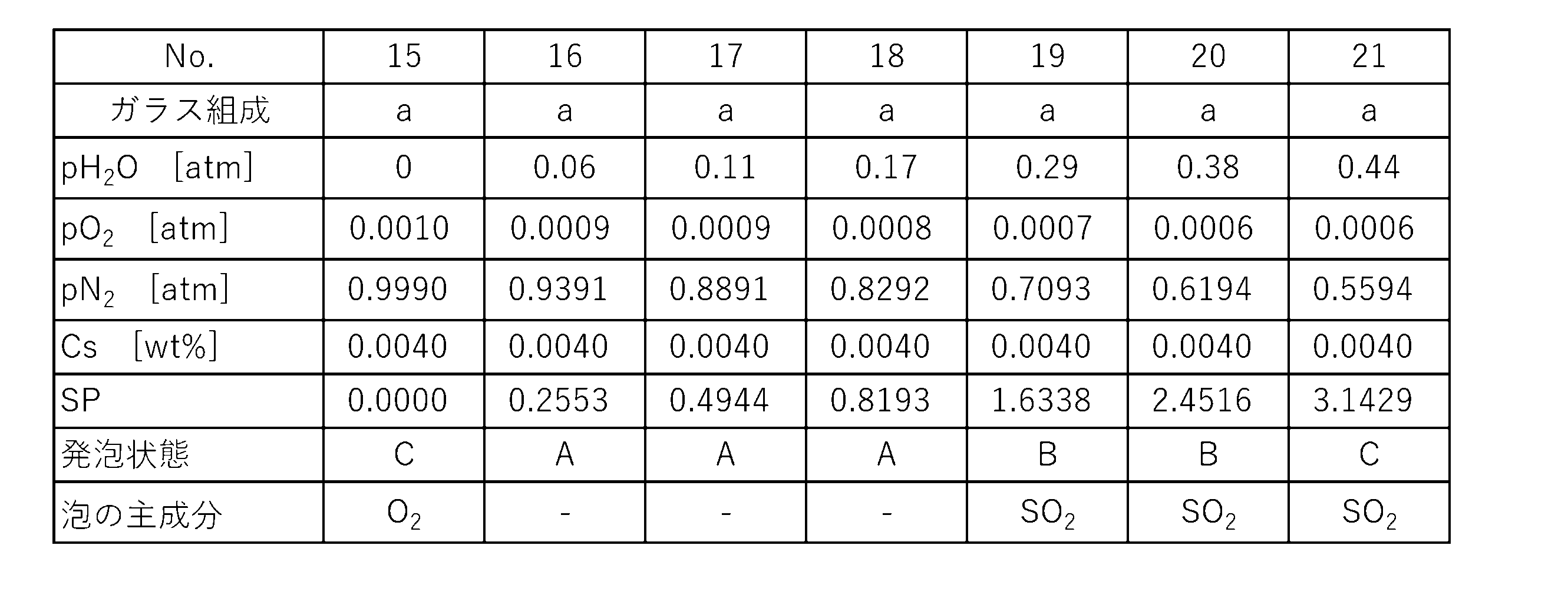


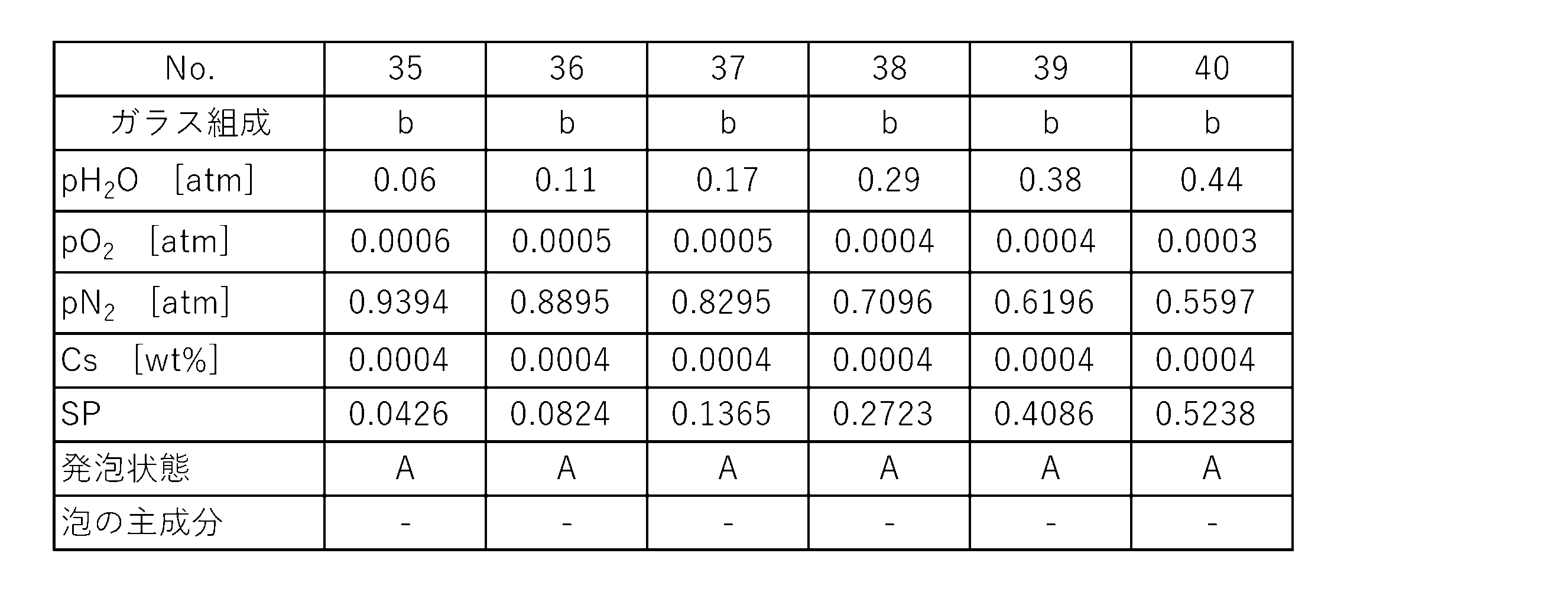
表1~6から明らかなように、例No.21、27、28は、SP値が過大であったため、SO2泡の発泡が認められた。一方、他例はSP値が抑制された結果、SO2泡の発泡が少ないか、或いは発泡が認められなかった。
本発明のガラスの製造方法は、バイアルやアンプル等の管瓶や注射器のシリンジといった医薬容器の材料として有用である。
1 ガラス製造装置
10 ガラス収容容器
11 原料供給管
12 原料調合装置
13 ガラス送出管
20 包囲容器
21 外囲空間
30 調整装置
40 酸素分圧センサ(酸素分圧測定手段)
41 酸素供給装置(酸素供給手段)
50 水蒸気分圧センサ(水蒸気分圧測定手段)
51 水蒸気供給装置(水蒸気供給手段)
60 コントローラ
J 実験装置
Q 石英容器
E 電気炉
T 金属管
G 溶融ガラス
10 ガラス収容容器
11 原料供給管
12 原料調合装置
13 ガラス送出管
20 包囲容器
21 外囲空間
30 調整装置
40 酸素分圧センサ(酸素分圧測定手段)
41 酸素供給装置(酸素供給手段)
50 水蒸気分圧センサ(水蒸気分圧測定手段)
51 水蒸気供給装置(水蒸気供給手段)
60 コントローラ
J 実験装置
Q 石英容器
E 電気炉
T 金属管
G 溶融ガラス
Claims (9)
- 溶融ガラスを、白金または白金合金からなる金属壁と接触した状態で、保持または流動させる工程を備えるガラスの製造方法であって、
前記溶融ガラスは、SO3飽和溶解度が0.05(wt%)以下であり、
前記溶融ガラスの硫黄濃度CS(wt%)、前記金属壁の外囲空間の水蒸気分圧pH2O(atm)、および前記金属壁の外囲空間の酸素分圧pO2(atm)とした場合に式(1)により算出される数値SPが、SP≦3.10となるよう、前記硫黄濃度CS、前記水蒸気分圧pH2O、および前記酸素分圧pO2の少なくともいずれかを調整する調整工程をさらに備えることを特徴とするガラスの製造方法。
SP=CS×pH2O/pO2 (1) - 前記調整工程において、0.0013≦SPとなるよう前記硫黄濃度CS、前記水蒸気分圧pH2O、前記酸素分圧pO2の少なくともいずれかを調整する、請求項1に記載のガラスの製造方法。
- 前記調整工程において、0.0040≦SP≦1.30となるよう前記硫黄濃度CS、前記水蒸気分圧pH2O、前記酸素分圧pO2の少なくともいずれかを調整する、請求項1または2に記載のガラスの製造方法。
- 前記金属壁の外囲空間に、
当該外囲空間の前記酸素分圧pO2を測定する酸素分圧測定手段と、
当該外囲空間へ酸素を供給する酸素供給手段と、を設け、
測定された前記酸素分圧pO2に基づき前記酸素の供給量を調整することにより、前記酸素分圧pO2を0.0008~0.17(atm)の範囲内に調整する、請求項1または2に記載のガラスの製造方法。 - 前記金属壁の外囲空間に、
当該外囲空間内の前記水蒸気分圧pH2Oを測定する水蒸気分圧測定手段と、
当該外囲空間へ水蒸気を供給する水蒸気供給手段と、を設け、
測定された前記水蒸気分圧pH2Oに基づき前記水蒸気の供給量を調整することにより、前記水蒸気分圧pH2Oを0.07~0.37(atm)の範囲内に調整する、請求項1または2に記載のガラスの製造方法。 - 前記溶融ガラスを得るためのガラス原料を調合する工程をさらに含み、前記ガラス原料におけるSO3含有量を調整することにより、前記硫黄濃度CSを、0.005wt%以下に調整する、請求項1または2に記載のガラスの製造方法。
- 前記金属壁に接触する前記溶融ガラスの粘度が104.0dPa・s以下である、請求項1または2に記載のガラスの製造方法。
- 前記溶融ガラスを成形して得られるガラスが、ガラス組成として質量%で、SiO2 65~80%、B2O3 9.5~15%を含有する、請求項1または2に記載のガラスの製造方法。
- 前記溶融ガラスを成形して得られるガラスが、ガラス組成として、質量%で、SiO2 50~70%、Al2O3 12~25%、B2O3 0~12%、Li2O+Na2O+K2O(Li2O、Na2O及びK2Oの合量) 0~1%未満、MgO 0~8%、CaO 0~15%、SrO 0~12%、BaO 0~15%を含有する、請求項1または2に記載のガラスの製造方法。
Applications Claiming Priority (2)
| Application Number | Priority Date | Filing Date | Title |
|---|---|---|---|
| JP2023201261A JP2025086957A (ja) | 2023-11-29 | 2023-11-29 | ガラスの製造方法 |
| JP2023-201261 | 2023-11-29 |
Publications (1)
| Publication Number | Publication Date |
|---|---|
| WO2025115461A1 true WO2025115461A1 (ja) | 2025-06-05 |
Family
ID=95896704
Family Applications (1)
| Application Number | Title | Priority Date | Filing Date |
|---|---|---|---|
| PCT/JP2024/037633 Pending WO2025115461A1 (ja) | 2023-11-29 | 2024-10-22 | ガラスの製造方法 |
Country Status (2)
| Country | Link |
|---|---|
| JP (1) | JP2025086957A (ja) |
| WO (1) | WO2025115461A1 (ja) |
Citations (3)
| Publication number | Priority date | Publication date | Assignee | Title |
|---|---|---|---|---|
| JP2001503008A (ja) * | 1996-10-28 | 2001-03-06 | コーニング インコーポレイテッド | ガラスの成形方法 |
| JP2015187081A (ja) * | 2011-10-11 | 2015-10-29 | AvanStrate株式会社 | ガラス板の製造方法 |
| WO2023089917A1 (ja) * | 2021-11-19 | 2023-05-25 | 日本電気硝子株式会社 | 医薬容器用ホウケイ酸ガラス、医薬容器用ガラス管及び医薬容器用ホウケイ酸ガラスの製造方法 |
-
2023
- 2023-11-29 JP JP2023201261A patent/JP2025086957A/ja active Pending
-
2024
- 2024-10-22 WO PCT/JP2024/037633 patent/WO2025115461A1/ja active Pending
Patent Citations (3)
| Publication number | Priority date | Publication date | Assignee | Title |
|---|---|---|---|---|
| JP2001503008A (ja) * | 1996-10-28 | 2001-03-06 | コーニング インコーポレイテッド | ガラスの成形方法 |
| JP2015187081A (ja) * | 2011-10-11 | 2015-10-29 | AvanStrate株式会社 | ガラス板の製造方法 |
| WO2023089917A1 (ja) * | 2021-11-19 | 2023-05-25 | 日本電気硝子株式会社 | 医薬容器用ホウケイ酸ガラス、医薬容器用ガラス管及び医薬容器用ホウケイ酸ガラスの製造方法 |
Also Published As
| Publication number | Publication date |
|---|---|
| JP2025086957A (ja) | 2025-06-10 |
Similar Documents
| Publication | Publication Date | Title |
|---|---|---|
| JP5109162B2 (ja) | ガラス製造方法 | |
| JP5236460B2 (ja) | ガラスを清澄する方法 | |
| TWI364407B (en) | Glass for display substrate | |
| US5785726A (en) | Method of reducing bubbles at the vessel/glass interface in a glass manufacturing system | |
| JP5105571B2 (ja) | 無アルカリガラスの製造方法 | |
| JP5002731B2 (ja) | ガラス板製造方法 | |
| JP7761879B2 (ja) | ガラス | |
| WO2011078258A1 (ja) | 溶融ガラスの減圧脱泡方法およびガラス製品の製造方法 | |
| JP6983377B2 (ja) | ガラス | |
| JP5194682B2 (ja) | ガラスの製造方法 | |
| JP5263719B2 (ja) | 無アルカリガラスの製造方法 | |
| US11584680B2 (en) | Alkali-free glass substrate | |
| JP2008201617A (ja) | ガラスの製造方法 | |
| JP5730806B2 (ja) | ガラス基板の製造方法 | |
| KR101798288B1 (ko) | 유리 기판의 제조 방법 및 유리 기판의 제조 장치 | |
| JP2025086957A (ja) | ガラスの製造方法 | |
| US10974986B2 (en) | Alkali-free glass substrate | |
| TWI388524B (zh) | 融化玻璃用耐熱材料、玻璃物品製造裝置以及玻璃物品的製造方法 | |
| US11718553B2 (en) | Alkali-free glass substrate | |
| JP2007077004A (ja) | ガラス熔融用耐熱材、ガラス物品製造装置及びガラス物品の製造方法 |
Legal Events
| Date | Code | Title | Description |
|---|---|---|---|
| 121 | Ep: the epo has been informed by wipo that ep was designated in this application |
Ref document number: 24897151 Country of ref document: EP Kind code of ref document: A1 |