WO2025115243A1 - クリップ式コネクタおよび機器 - Google Patents
クリップ式コネクタおよび機器 Download PDFInfo
- Publication number
- WO2025115243A1 WO2025115243A1 PCT/JP2024/010027 JP2024010027W WO2025115243A1 WO 2025115243 A1 WO2025115243 A1 WO 2025115243A1 JP 2024010027 W JP2024010027 W JP 2024010027W WO 2025115243 A1 WO2025115243 A1 WO 2025115243A1
- Authority
- WO
- WIPO (PCT)
- Prior art keywords
- clip
- type connector
- elastic
- elastic portion
- wall
- Prior art date
- Legal status (The legal status is an assumption and is not a legal conclusion. Google has not performed a legal analysis and makes no representation as to the accuracy of the status listed.)
- Pending
Links
Images


Classifications
-
- H—ELECTRICITY
- H01—ELECTRIC ELEMENTS
- H01R—ELECTRICALLY-CONDUCTIVE CONNECTIONS; STRUCTURAL ASSOCIATIONS OF A PLURALITY OF MUTUALLY-INSULATED ELECTRICAL CONNECTING ELEMENTS; COUPLING DEVICES; CURRENT COLLECTORS
- H01R11/00—Individual connecting elements providing two or more spaced connecting locations for conductive members which are, or may be, thereby interconnected, e.g. end pieces for wires or cables supported by the wire or cable and having means for facilitating electrical connection to some other wire, terminal, or conductive member, blocks of binding posts
- H01R11/11—End pieces or tapping pieces for wires, supported by the wire and for facilitating electrical connection to some other wire, terminal or conductive member
- H01R11/22—End pieces terminating in a spring clip
-
- H—ELECTRICITY
- H01—ELECTRIC ELEMENTS
- H01R—ELECTRICALLY-CONDUCTIVE CONNECTIONS; STRUCTURAL ASSOCIATIONS OF A PLURALITY OF MUTUALLY-INSULATED ELECTRICAL CONNECTING ELEMENTS; COUPLING DEVICES; CURRENT COLLECTORS
- H01R4/00—Electrically-conductive connections between two or more conductive members in direct contact, i.e. touching one another; Means for effecting or maintaining such contact; Electrically-conductive connections having two or more spaced connecting locations for conductors and using contact members penetrating insulation
- H01R4/28—Clamped connections, spring connections
- H01R4/48—Clamped connections, spring connections utilising a spring, clip, or other resilient member
Definitions
- the present invention relates to clip-type connectors and devices.
- Patent Document 1 discloses a female terminal assembly that receives a male terminal between a pair of protrusions that are spaced apart from each other by a distance shorter than the thickness of the male terminal.
- Patent Documents 2-16 disclose techniques relating to clip-type or clamp-type connectors.
- Patent Document 1 Japanese Patent No. 5156864
- Patent Document 2 Japanese Utility Model Publication No. 4-009752
- Patent Document 3 Japanese Utility Model Publication No. 4-009753
- Patent Document 4 Japanese Utility Model Publication No. 56-076274
- Patent Document 5 Japanese Patent Publication No. 6-028177
- Patent Document 6 Japanese Patent No. 3546479
- Patent Document 7 Japanese Patent No. 5158551
- Patent Document 8 Japanese Patent No.
- Patent Document 9 Japanese Patent No. 6754031
- Patent Document 10 Japanese Patent No. 7004542
- Patent Document 11 Japanese Patent Publication No. 2007-234373
- Patent Document 12 Japanese Patent Publication No. 2018-156734
- Patent Document 13 Japanese Patent Publication No. 2022-122739
- Patent Document 14 Japanese Patent Publication No. 2023-047375
- Patent Document 15 JP-A-09-223527
- Patent Document 16 Utility Model Registration No. 3024960
- a clip-type connector in a first aspect of the present invention, includes a base having a main surface.
- the clip-type connector includes a wall portion erected from the base.
- the clip-type connector includes a first elastic portion and a second elastic portion located on the wall portion opposite the base and spaced apart from each other in a direction along the main surface.
- the clip-type connector includes a connecting portion connecting the first elastic portion and the second elastic portion, the connecting portion facing the main surface and located on the side of the first elastic portion and the second elastic portion opposite the wall portion.
- the clip-type connector includes a first extension portion extending from the connecting portion toward the wall portion between the first elastic portion and the second elastic portion.
- the connecting portion may have a curved portion that curves toward the wall portion at least between the first elastic portion and the second elastic portion on the side opposite the first elastic portion and the second elastic portion.
- the first extension portion may extend toward the wall portion from the side of the curved portion opposite the first elastic portion and the second elastic portion.
- the first extension portion may extend from the first elastic portion and the second elastic portion side of the connecting portion toward the wall portion.
- any of the clip-type connectors described above may further include a second extension portion that extends from the first extension portion on the opposite side to the connecting portion in a direction away from the base portion.
- At least a portion of the second extension portion may be located between the first elastic portion and the second elastic portion in a direction along the main surface.
- the end of the wall portion opposite the base portion may be located lower than the first extension portion relative to the base portion.
- the end of the first extension portion on the wall side may be located closer to the wall side than the connecting portion between the first elastic portion and the second elastic portion.
- the connecting portion may have an electrical contact at a position opposite the main surface.
- the first extension portion may have a jig receiving portion that abuts against a jig used to attach the clip-type connector to a workpiece.
- a clip-type connector in a second aspect of the present invention, includes a base having a main surface.
- the clip-type connector includes a wall portion erected from the base.
- the clip-type connector includes an elastic portion located on the wall portion opposite the base.
- the clip-type connector includes a contact portion facing the main surface and located on the elastic portion opposite the wall portion.
- the clip-type connector includes extension portions located on both sides of the elastic portion in a direction along the main surface and extending from the contact portion toward the wall portion.
- a device in a third aspect of the present invention, includes any of the clip-type connectors described above and a mounting member to which the clip-type connector is attached.
- the end of the wall portion opposite the base may be located higher than the portion of the base where the clip-type connector is attached to the mounting member.
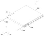
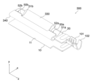
- FIG. 1 is a perspective view of a device 5 equipped with a clip-type connector 100 according to a first embodiment.
- FIG. 1 is a perspective view of a clip-type connector 100.
- FIG. 2 is a top view of the clip-type connector 100.
- 1 is a cross-sectional view of a clip-type connector 100.
- FIG. 1 is a perspective view showing a state in which a jig 150 is applied to a clip-type connector 100.
- FIG. 6 shows a cross section of the clip-type connector 100 and the jig 150 in the situation of FIG. 5.
- 11 is a cross-sectional view showing a state in which the electrical contact 42 is lifted in the positive direction of the y-axis by a jig 150.
- FIG. 1 is a perspective view of a device 5 equipped with a clip-type connector 100 according to a first embodiment.
- FIG. 1 is a perspective view of a clip-type connector 100.
- FIG. 2 is a top view
- FIG. 1 is a cross-sectional view showing a state in which the clip-type connector 100 is attached to a workpiece 140 with the electrical contact 42 lifted by a jig 150.
- FIG. 1 is a cross-sectional view showing a state in which a jig 150 has been removed from a clip-type connector 100 after the clip-type connector 100 has been attached to a workpiece 140.
- FIG. 1 is a cross-sectional view of a clip-type connector 200 which is a modified example of the clip-type connector 100.
- FIG. FIG. 11 is a perspective view showing a clip-type connector 300 according to a second embodiment.
- FIG. 1 shows an oblique view of a device 5 equipped with a clip-type connector 100 according to the first embodiment.
- the device 5 includes a clip-type connector 110, a mounting member 140, an electric wire 120, and an electric wire 130.
- the clip-type connector 100 and the clip-type connector 110 are attached to the mounting member 140 by clamping the mounting member 140.
- the mounting member 140 may be, for example, a plate-shaped member such as a solar panel, but is not limited to this.
- the clip-type connector 100 is fixed to the clip-type connector 100 so that the electric wire 120 and the clip-type connector 100 are electrically connected.
- the clip-type connector 110 is fixed to the clip-type connector 110 so that the electric wire 130 and the clip-type connector 110 are electrically connected.
- the clip-type connector 110 has the same configuration as the clip-type connector 100. Therefore, detailed explanation of the clip-type connector 110 will be omitted.
- the main purpose is to clearly explain the configuration of the device 5, and a right-handed Cartesian coordinate system having an x-axis, a y-axis, and a z-axis is shown along with the configuration of the device 5 or the clip-type connector 100, etc.
- the configuration of the device 5 or the clip-type connector 100, etc. may be explained using this Cartesian coordinate system.
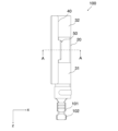
- FIG. 2 is a perspective view of the clip-type connector 100.
- FIG. 3 is a top view of the clip-type connector 100.
- FIG. 4 is a cross-sectional view of the clip-type connector 100. Specifically, FIG. 4 shows the A-A cross section of FIG. 3.
- the clip-type connector 100 is formed from a conductive material.
- the clip-type connector 100 is formed from, for example, a metal material.
- the clip-type connector 100 is formed from, for example, a single metal plate.
- the clip-type connector 100 includes a base 10, a wall portion 20, a first elastic portion 31, a second elastic portion 32, a connecting portion 40, an extension portion 50, a first crimp portion 101, and a second crimp portion 102.
- the conductive member of the electric wire 120 is crimped to the first crimping portion 101 while the conductive member of the electric wire 120 is electrically connected to the first crimping portion 101.
- the covering member of the conductive member of the electric wire 120 is crimped to the second crimping portion 102. As a result, the electric wire 120 is substantially fixed to the clip-type connector 100.
- the base 10 has a principal surface 11.
- the principal surface 11 extends in a direction along the z-axis.
- the wall portion 20 stands upright from the base portion 10. Specifically, the wall portion 20 stands upright from the main surface 11 of the base portion 10. The wall portion 20 stands upright from the main surface 11 of the base portion 10 in the positive y-axis direction.
- the first elastic portion 31 and the second elastic portion 32 are located on the opposite side of the wall portion 20 from the base portion 10.
- the first elastic portion 31 and the second elastic portion 32 are spaced apart from each other in a direction along the main surface 11.
- the connecting portion 40 connects the first elastic portion 31 and the second elastic portion 32.
- the connecting portion 40 connects the first elastic portion 31 and the second elastic portion 32 in the direction along the z-axis.
- the connecting portion 40 faces the main surface 11 and is located on the opposite side of the first elastic portion 31 and the second elastic portion 32 from the wall portion 20.
- the connecting portion 40 has an electrical contact 42 at a position facing the main surface 11.
- the connecting portion 40 has a curved portion 41.
- the electrical contact 42 is a portion near the apex of the curved portion 41. Specifically, the electrical contact 42 is a portion near the apex of the curved portion 41 in the y-axis direction.
- the base 10, the wall 20, the first elastic portion 31 and the second elastic portion 32, and the connecting portion 40 have a shape that surrounds the space 103 while forming a space 103 and a gap 104 for receiving the member to be attached 140.
- a force in the positive direction of the z-axis is applied to the connecting portion 40, a restoring force in the negative direction of the z-axis is generated in the first elastic portion 31 and the second elastic portion 32.
- the restoration of the first elastic portion 31 and the second elastic portion 32 can cause the member to be attached 140 to be sandwiched between the electrical contact 42 and the main surface 11.
- the electrical contact 42 is pressed against the member to be attached 140.
- the extension portion 50 extends from the connecting portion 40 toward the wall portion 20 between the first elastic portion 31 and the second elastic portion 32, as shown in, for example, Figures 2 and 3.
- the extension portion 50 has a first extension portion 51 and a second extension portion 52.
- the first extension portion 51 extends from the connecting portion 40 toward the wall portion 20 between the first elastic portion 31 and the second elastic portion 32, as shown in, for example, Figure 4.
- the first extension portion 51 extends mainly in the positive direction of the x-axis.
- the connecting portion 40 has a curved portion 43 on the opposite side to the first elastic portion 31 and the second elastic portion 32.
- the curved portion 43 curves toward the wall portion 20 at least between the first elastic portion 31 and the second elastic portion 32.
- the first extension portion 51 extends toward the wall portion 20 from the opposite side of the curved portion 43 to the first elastic portion 31 and the second elastic portion 32.
- the connecting portion 40 has a second extension portion 52 that extends from the opposite side of the first extension portion 51 to the connecting portion 40 in a direction away from the base portion 10.
- the first extension portion 51 extends mainly in the positive direction of the x-axis
- the second extension portion 52 extends mainly in the positive directions of the x-axis and the y-axis. In this way, at least a portion of the second extension portion 52 is located between the first elastic portion 31 and the second elastic portion 32 in the direction along the main surface 11.
- the first extension portion 51 has a jig receiving portion 53 that abuts against a jig used to attach the clip-type connector 100 to the attachment member 140.
- the jig receiving portion 53 is a portion of the first extension portion 51 near the second extension portion 52. The jig receiving portion 53 will be described later.
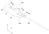
- FIG. 5 is a perspective view showing a situation in which a jig 150 is applied to the clip-type connector 100.
- the jig 150 is used when attaching the clip-type connector 100 to the workpiece 140. Specifically, the jig 150 is used to widen the gap between the main surface 11 and the electrical contacts 42.
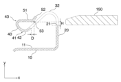
- FIG. 6 shows a cross-section of the clip-type connector 100 and the jig 150 in the situation of FIG. 5.
- FIG. 7 is a cross-sectional view showing a situation in which the electrical contacts 42 have been lifted in the positive direction of the y-axis by the jig 150.
- FIGS. 6 and 7 are cross-sectional views at the same position as A-A in FIG. 3.
- the jig 150 is inserted between the first elastic portion 31 and the second elastic portion 32.
- the jig 150 is inserted in a direction from the wall portion 20 toward the connecting portion 40.
- the jig 150 can be inserted in the negative x-axis direction.
- the end portion 21 of the wall portion 20 opposite the base portion 10 is located lower than the first extension portion 51 with respect to the base portion 10. Specifically, as shown in FIG. 6, the end portion 21 is located lower than the first extension portion 51 by H in the y-axis direction. Therefore, when the jig 150 is inserted in a direction from the wall portion 20 toward the connecting portion 40 (the negative direction of the x-axis), the jig 150 abuts against the jig receiving portion 53 of the second extension portion 52.
- the second extension portion 52 extends in a direction toward the wall portion 20 and in a direction away from the base portion 10. This allows the jig 150 to be guided in a direction toward the jig receiving portion 53 even if the position at which the jig 150 is inserted is slightly shifted in the positive direction of the y axis.
- the insertion position of the jig 150 in the z axis direction is regulated by the first elastic portion 31 and the second elastic portion 32, and at least a portion of the second extension portion 52 is located between the first elastic portion 31 and the second elastic portion 32 in the direction along the z axis, so that when the jig 150 is inserted, the jig 150 can be reliably abutted against the second extension portion 52.
- the end of the first extension portion 51 on the wall portion 20 side is located closer to the wall portion 20 than the connecting portion 40. Specifically, as shown in FIG. 6, the end of the first extension portion 51 on the wall portion 20 side is located closer to the wall portion 20 by a distance D in the x-axis direction than the end of the connecting portion 40 on the wall portion 20 side.
- This allows the jig 150 to be received by the connecting portion 40, so that the jig 150 can be positioned in the insertion direction (x-axis negative direction) before the jig 150 lifts the jig receiving portion 53. Therefore, before the jig 150 lifts the jig receiving portion 53, the jig 150 can be positioned at a position where the jig 150 can reliably lift the jig receiving portion 53.
- Figure 8 is a cross-sectional view showing the state in which the clip-type connector 100 is attached to the workpiece 140 with the electrical contact 42 lifted by the jig 150.
- Figure 8 is a cross-sectional view taken at the same position as A-A in Figure 3.
- the mounting member 140 is provided with electrodes 142. As shown in FIG. 8, the clip-type connector 100 can be inserted into the mounting member 140 with the electric contact 42 raised above the main surface 11 by the jig 150. This prevents the electric contact 42 from exerting a strong force on the electrode 142 and other parts of the mounting member 140 while the clip-type connector 100 is being inserted into the mounting member 140. This prevents the electric contact 42 from abrading the electrode 142 and other parts of the mounting member 140 with a strong force, thereby preventing electrical connection failures and the like.
- the clip-type connector 100 prevents the electrode 142 from being abraded even if the electrode 142 is formed by plating or printing.
- Figure 9 is a cross-sectional view showing the state in which the jig 150 has been removed from the clip-type connector 100 after the clip-type connector 100 has been attached to the workpiece 140.
- Figure 9 is a cross-sectional view taken at the same position as A-A in Figure 3.
- the end 21 of the wall 20 opposite the base is located higher than the portion of the base 10 where the clip-type connector 100 is attached to the workpiece 140. Specifically, as shown in FIG. 9, the end 21 is located a height h higher than the position of the electrode 142. This allows the height of the jig 150 to be regulated when the jig 150 is removed from the clip-type connector 100, so that the jig 150 does not apply a strong force to the electrode 142 and other portions of the workpiece 140. Furthermore, when the jig 150 is being inserted into the clip-type connector 100 to replace the clip-type connector 100, the jig 150 does not apply a strong force to the electrode 142 and other portions of the workpiece 140.
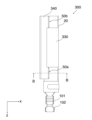
- FIG. 10 is a cross-sectional view of a clip-type connector 200 that is a modified version of the clip-type connector 100.
- the clip-type connector 200 differs from the clip-type connector 100 in that the position and structure of the extension portion that abuts against the jig 150 is different from the extension portion 50 of the clip-type connector 100.
- the same components as those of the clip-type connector 100 are given the same reference numbers as the corresponding reference numbers given to the components of the clip-type connector 100, and their description will be omitted.
- Figure 10 is a cross-sectional view of a position corresponding to Figure 4.
- Clip-type connector 200 has a connecting portion 240 and an extension portion 250 instead of connecting portion 40 and extension portion 50 of clip-type connector 100.
- the connecting portion 240 has an electrical contact 242 having a shape corresponding to the electrical contact 42, and a curved portion 241 having a shape corresponding to the curved portion 41.
- the extension portion 50 of the clip-type connector 100 has a structure that extends from the side of the connecting portion 40 opposite the first elastic portion 31 and the second elastic portion 31 toward the wall portion 20, whereas the extension portion 250 of the clip-type connector 200 extends from the first elastic portion 31 and the second elastic portion 31 side of the connecting portion 40 toward the wall portion 20 between the first elastic portion 31 and the second elastic portion 32.
- the opening 253 functions as a jig receiving portion that receives the jig 150 inserted in the negative direction of the x-axis. This allows the jig 150 to be used to lift the electrical contact 242 in the positive direction of the y-axis. Therefore, the clip-type connector 200 can also prevent strong forces from being applied from the electrical contact 242 and the jig 150 to the electrode 142 and other parts of the workpiece 140 when the clip-type connector 200 is attached to the workpiece 140.
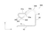
- FIG. 11 is a perspective view showing a clip-type connector 300 according to the second embodiment.
- the clip-type connector 100 has a first elastic portion 31, a second elastic portion 32, and an extension portion 50 between the first elastic portion 31 and the second elastic portion 32, whereas the clip-type connector 300 has one elastic portion 330 and extension portions 50a and 50b on either side of the elastic portion 330, which is different from the clip-type connector 100.
- the same components as those of the clip-type connector 100 are given the same reference numbers as the corresponding reference numbers given to the components of the clip-type connector 100, and their description will be omitted.
- the clip-type connector 300 comprises a base 10, a wall 20, an elastic portion 330, a contact portion 340, an extension portion 50a, an extension portion 50b, a first crimp portion 101, and a second crimp portion 102.
- the elastic portion 330 is located on the side of the wall 20 opposite the base 10.
- the contact portion 340 faces the main surface 11 and is located on the side of the elastic portion 330 opposite the wall 20.
- the extension portion 50a is located on one side of the elastic portion 330 in the direction along the main surface 11, and extends from the contact portion 340 towards the wall portion 20.
- the extension portion 50b is located on the other side of the elastic portion 330 in the direction along the main surface 11, and extends from the contact portion 340 towards the wall portion 20.
- the clip-type connector 300 has extensions located on both sides of the elastic portion 330 in the direction along the main surface 11 and extending from the contact portion 340 toward the wall portion 20.
- FIG. 12 is a top view of the clip-type connector 300.
- FIG. 13 is a cross-sectional view of the clip-type connector 300. Specifically, FIG. 13 shows the cross-section B-B in FIG. 12. Since extension portion 50b has the same structure as extension portion 50a, illustration of the cross-section and detailed description will be omitted.
- the contact portion 340 has an electrical contact 342 at a position facing the main surface 11.
- the contact portion 340 has a curved portion 341.
- the electrical contact 342 is a portion near the apex of the curved portion 341.
- the electrical contact 342 is a portion near the apex of the curved portion 341 in the y-axis direction.
- the extension portion 50a extends from the contact portion 340 toward the wall portion 20, as shown in FIG. 13, for example.
- the extension portion 50a has a first extension portion 51a and a second extension portion 52a.
- the first extension portion 51a extends from the contact portion 340 toward the wall portion 20 on one side of the elastic portion 330, as shown in FIG. 13, for example.
- the first extension portion 51a extends mainly in the positive direction of the x-axis.
- the extension portion 50a has a second extension portion 52a that extends from the opposite side of the first extension portion 51a to the contact portion 340 in a direction away from the base portion 10. As shown in FIG. 13 etc., the first extension portion 51a extends mainly in the positive direction of the x-axis, whereas the second extension portion 52a extends mainly in the positive direction of the x-axis and the positive direction of the y-axis.
- the first extension portion 51a has a jig receiving portion 53a that abuts against a jig 150 used to attach the clip-type connector 300 to the attachment member 140.
- the jig receiving portion 53a is a portion of the first extension portion 51a near the second extension portion 52a.
- the shape of the B-B cross section of the clip-type connector 300 is the same as the shape of the A-A cross section of the clip-type connector 100. This makes it possible for the clip-type connector 300 to prevent strong forces from being applied from the electrical contacts 342 and the jig 150 to the electrodes 142 and other parts of the workpiece 140 when the clip-type connector 300 is attached to the workpiece 140.
- the clip-type connectors 100, 200, and 300 can be attached to the mounting member 140 without applying strong force from the electrical contacts 342 and the jig 150. Furthermore, the clip-type connectors 100, 200, and 300 can electrically connect the conductive member of the electric wire to the electrode 142 through the first crimping portion 101. Therefore, there is no need to solder the conductive member of the electric wire to the electrode 142. Therefore, there is no need to make the mounting member 140 and the electrode 142 heat-resistant. In addition, the electric wire can be easily removed from the mounting member 140.
Landscapes
- Details Of Connecting Devices For Male And Female Coupling (AREA)
Priority Applications (1)
| Application Number | Priority Date | Filing Date | Title |
|---|---|---|---|
| JP2025560533A JPWO2025115243A1 (https=) | 2023-11-29 | 2024-03-14 |
Applications Claiming Priority (2)
| Application Number | Priority Date | Filing Date | Title |
|---|---|---|---|
| US202363604144P | 2023-11-29 | 2023-11-29 | |
| US63/604,144 | 2023-11-29 |
Publications (1)
| Publication Number | Publication Date |
|---|---|
| WO2025115243A1 true WO2025115243A1 (ja) | 2025-06-05 |
Family
ID=95896591
Family Applications (1)
| Application Number | Title | Priority Date | Filing Date |
|---|---|---|---|
| PCT/JP2024/010027 Pending WO2025115243A1 (ja) | 2023-11-29 | 2024-03-14 | クリップ式コネクタおよび機器 |
Country Status (2)
| Country | Link |
|---|---|
| JP (1) | JPWO2025115243A1 (https=) |
| WO (1) | WO2025115243A1 (https=) |
Citations (5)
| Publication number | Priority date | Publication date | Assignee | Title |
|---|---|---|---|---|
| US2434720A (en) * | 1944-06-26 | 1948-01-20 | Adel Prec Products Corp | Mounting means for flexible strap clips |
| JPH0629050A (ja) * | 1990-01-19 | 1994-02-04 | Amp Inc | 接続クリップ |
| US6106310A (en) * | 1997-11-19 | 2000-08-22 | The Whitaker Corporation | Panel-grounding contact |
| JP2000331723A (ja) * | 1999-03-17 | 2000-11-30 | Jst Mfg Co Ltd | アース用クリップ端子とこれを含む接地構造 |
| US7686625B1 (en) * | 2008-11-07 | 2010-03-30 | Tyco Electronics Corporation | Grounding clip |
-
2024
- 2024-03-14 JP JP2025560533A patent/JPWO2025115243A1/ja active Pending
- 2024-03-14 WO PCT/JP2024/010027 patent/WO2025115243A1/ja active Pending
Patent Citations (5)
| Publication number | Priority date | Publication date | Assignee | Title |
|---|---|---|---|---|
| US2434720A (en) * | 1944-06-26 | 1948-01-20 | Adel Prec Products Corp | Mounting means for flexible strap clips |
| JPH0629050A (ja) * | 1990-01-19 | 1994-02-04 | Amp Inc | 接続クリップ |
| US6106310A (en) * | 1997-11-19 | 2000-08-22 | The Whitaker Corporation | Panel-grounding contact |
| JP2000331723A (ja) * | 1999-03-17 | 2000-11-30 | Jst Mfg Co Ltd | アース用クリップ端子とこれを含む接地構造 |
| US7686625B1 (en) * | 2008-11-07 | 2010-03-30 | Tyco Electronics Corporation | Grounding clip |
Also Published As
| Publication number | Publication date |
|---|---|
| JPWO2025115243A1 (https=) | 2025-06-05 |
Similar Documents
| Publication | Publication Date | Title |
|---|---|---|
| US6033245A (en) | Self-aligning electrical connector | |
| JP4187338B2 (ja) | 電気コネクタ | |
| US9039429B2 (en) | Wire-to-board connector | |
| JPS61237375A (ja) | レセプタクル端子 | |
| CN1577991A (zh) | 一种连接组件 | |
| US8882544B2 (en) | Connector | |
| TW202123544A (zh) | 連接器組件 | |
| CN1871747A (zh) | 连接器及连接器系统 | |
| CN102474032A (zh) | 用于插接式插座的接触弹簧 | |
| JP6193122B2 (ja) | 雄電気端子 | |
| JP2015158990A (ja) | フローティング型コネクタ | |
| JPH08213119A (ja) | 電気コネクタ | |
| CN1209854C (zh) | 带有基板用接地插头的连接器 | |
| TW200828690A (en) | Electrical contact | |
| WO2025115243A1 (ja) | クリップ式コネクタおよび機器 | |
| JPH07135038A (ja) | 表面実装用コネクタ | |
| JP4913539B2 (ja) | ソケットコンタクト | |
| TW200532997A (en) | Electrical connector assembly | |
| JP3523030B2 (ja) | 端子構造 | |
| JP4502544B2 (ja) | フラットケーブル用端子 | |
| JP4386676B2 (ja) | コネクタ | |
| JP3265843B2 (ja) | コネクタピン接続装置及びその組立方法 | |
| CN110277687B (zh) | 导线联接装置的导电组件结构 | |
| CN223566946U (zh) | 用于连接器的接插装置 | |
| CN220122150U (zh) | 一种快插母端及快插装置 |
Legal Events
| Date | Code | Title | Description |
|---|---|---|---|
| 121 | Ep: the epo has been informed by wipo that ep was designated in this application |
Ref document number: 24896935 Country of ref document: EP Kind code of ref document: A1 |
|
| ENP | Entry into the national phase |
Ref document number: 2025560533 Country of ref document: JP Kind code of ref document: A |
|
| WWE | Wipo information: entry into national phase |
Ref document number: 2025560533 Country of ref document: JP |