WO2025115216A1 - 室外機および冷凍サイクル装置 - Google Patents
室外機および冷凍サイクル装置 Download PDFInfo
- Publication number
- WO2025115216A1 WO2025115216A1 PCT/JP2023/043121 JP2023043121W WO2025115216A1 WO 2025115216 A1 WO2025115216 A1 WO 2025115216A1 JP 2023043121 W JP2023043121 W JP 2023043121W WO 2025115216 A1 WO2025115216 A1 WO 2025115216A1
- Authority
- WO
- WIPO (PCT)
- Prior art keywords
- outdoor unit
- heat exchanger
- outdoor
- unit according
- drain pan
- Prior art date
- Legal status (The legal status is an assumption and is not a legal conclusion. Google has not performed a legal analysis and makes no representation as to the accuracy of the status listed.)
- Pending
Links
Images



Classifications
-
- F—MECHANICAL ENGINEERING; LIGHTING; HEATING; WEAPONS; BLASTING
- F24—HEATING; RANGES; VENTILATING
- F24F—AIR-CONDITIONING; AIR-HUMIDIFICATION; VENTILATION; USE OF AIR CURRENTS FOR SCREENING
- F24F1/00—Room units for air-conditioning, e.g. separate or self-contained units or units receiving primary air from a central station
- F24F1/06—Separate outdoor units, e.g. outdoor unit to be linked to a separate room comprising a compressor and a heat exchanger
- F24F1/36—Drip trays for outdoor units
Definitions
- This technology relates to outdoor units and refrigeration cycle devices. In particular, it is intended to hide the equipment inside the outdoor unit.
- a top-flow type outdoor unit has an air outlet on the top surface of the housing, and an outdoor heat exchanger is installed on the side of the housing, surrounding a fan installed in the center. Since air flows into the outdoor heat exchanger, part of the outdoor heat exchanger can be seen from outside the outdoor unit.
- a heat exchanger with a pair of headers at both ends of the multiple heat transfer tubes that branch and merge the refrigerant (see, for example, Patent Document 1).
- the outdoor heat exchanger functions as a condenser
- high-temperature, high-pressure gas refrigerant flows from the compressor into the header of the outdoor heat exchanger.
- the header is arranged on the left and right, the metal sheets that make up the housing can function as pillars at the corners of the side of the housing to cover the header and conceal it from the outside.
- the objective is to solve the above problems and provide an outdoor unit and refrigeration cycle device that can drain water while hiding the header.
- the outdoor unit has a housing, a number of heat transfer tubes each connected to a pair of headers through which a fluid passes, the pair of headers are separated vertically into upper and lower parts, and the outdoor heat exchanger is installed along the side of the housing, the drainage section has a drainage hole that opens with a horizontally elongated edge, and a concealed panel is installed corresponding to the lower header on the lower side of the pair of headers to cover the lower header and hide it from the outside.
- the refrigeration cycle device disclosed herein also has the outdoor unit described above.
- the lower header can be hidden from the outside by installing a concealing panel in a position corresponding to the lower header.
- the concealing panel has a horizontally elongated drainage hole, which allows water that drips down the outdoor heat exchanger to be drained, preventing the dripping water from freezing and growing and reaching the lower header.
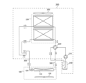
- FIG. 1 is a diagram showing the configuration of an air conditioning apparatus according to a first embodiment.
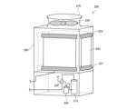
- 1 is a diagram illustrating a configuration of an outdoor unit 200 according to a first embodiment.
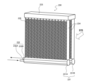
- FIG. 2 is a diagram illustrating a configuration of an outdoor heat exchanger 230 according to the first embodiment.
- FIG. 2 is a diagram illustrating the configuration of the periphery of an outdoor heat exchanger 230 in the outdoor unit 200 according to the first embodiment.
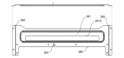
- FIG. 2 is a diagram showing a hidden panel 280 according to the first embodiment.
- FIG. 2 is a diagram showing the periphery of a concealed panel 280 in the outdoor unit 200 according to the first embodiment.
- FIG. 4 is a diagram showing a drain pan 290 according to the first embodiment.
- FIG. 1 is a diagram illustrating a configuration of an outdoor unit 200 according to a first embodiment.
- FIG. 2 is a diagram illustrating a configuration of an outdoor heat exchanger 230 according to the first embodiment.
- FIG. 2 is a diagram illustrating
- FIG. 2 is a diagram illustrating the positional relationship within an outdoor unit 200 of a lower header 231, a hidden panel 280, and a drain pan 290 of an outdoor heat exchanger 230 according to the first embodiment.
- FIG. FIG. 13 is a diagram showing a hidden panel 280 according to the second embodiment.
- FIG. 1 is a diagram showing the configuration of an air conditioner according to embodiment 1.
- the air conditioner will be described as an example of a refrigeration cycle apparatus having a heat exchanger according to embodiment 1.
- the air conditioning apparatus of the first embodiment has an outdoor unit 200, an indoor unit 100, and two refrigerant pipes 300.
- the compressor 210, four-way valve 220, and outdoor heat exchanger 230 of the outdoor unit 200 and the indoor heat exchanger 110 and expansion valve 120 of the indoor unit 100 are connected by refrigerant pipes 300 to form a refrigerant circuit.
- the air conditioning apparatus of the first embodiment has one outdoor unit 200 and one indoor unit 100 connected by piping.
- the number of connected units is not limited to this.
- the indoor unit 100 has an indoor heat exchanger 110, an expansion valve 120, and an indoor fan 130.
- the expansion valve 120 such as a throttling device, reduces the pressure of the refrigerant and expands it.
- the expansion valve 120 is configured as an electronic expansion valve, it adjusts its opening based on instructions from a control device (not shown).
- the indoor heat exchanger 110 exchanges heat between the refrigerant and the air in the room, which is the space to be air-conditioned.
- the indoor heat exchanger 110 functions as a condenser, condensing and liquefying the refrigerant.
- the indoor heat exchanger 110 functions as an evaporator, evaporating and vaporizing the refrigerant.
- the indoor fan 130 passes indoor air through the indoor heat exchanger 110 and supplies the air that has passed through the indoor heat exchanger 110 to the room.
- FIG. 2 is a diagram for explaining the configuration of the outdoor unit 200 according to the first embodiment.
- the outdoor unit 200 according to the first embodiment is a top-flow type having an outlet 270 of the outdoor fan 250 at the center of the upper part of a rectangular parallelepiped housing 260.
- the outdoor heat exchanger 230 is shown positioned in the upper part and the compressor 210 and the like are shown positioned in the lower part, but as shown in FIG. 4 described later, in the outdoor unit 200 according to the first embodiment, the outdoor heat exchanger 230 is arranged up to a position close to the bottom surface.
- the outdoor heat exchanger 230 is arranged so as to surround the compressor 210 and other devices.
- the outdoor unit 200 has a compressor 210, a four-way valve 220, an outdoor heat exchanger 230, and an accumulator 240 as devices that make up the refrigerant circuit.
- the compressor 210 compresses the refrigerant it draws in and discharges it.
- the compressor 210 is, for example, a scroll compressor, a reciprocating compressor, or a vane compressor.
- the capacity of the compressor 210 can be changed by arbitrarily changing the drive frequency, for example, by an inverter circuit or the like.
- the four-way valve 220 which serves as the flow path switching device, is a valve that switches the flow of the refrigerant depending on, for example, whether the cooling operation is performed or whether the heating operation is performed.
- the four-way valve 220 connects the discharge side of the compressor 210 to the indoor heat exchanger 110 during heating operation, and also connects the suction side of the compressor 210 to the outdoor heat exchanger 230. Furthermore, the four-way valve 220 connects the discharge side of the compressor 210 to the outdoor heat exchanger 230 during cooling operation, and also connects the suction side of the compressor 210 to the indoor heat exchanger 110.
- the flow path switching device is not limited to this.
- the flow path switching device may be configured, for example, by combining a plurality of two-way valves.
- the accumulator 240 is installed on the suction side of the compressor 210.
- the accumulator 240 passes a gaseous refrigerant (hereinafter referred to as a gaseous refrigerant) and accumulates a liquid refrigerant (hereinafter referred to as a liquid refrigerant).
- the outdoor heat exchanger 230 exchanges heat between the refrigerant and the outdoor air.
- the refrigerant is a fluid that serves as a heat exchange medium.
- the outdoor heat exchanger 230 of the first embodiment functions as an evaporator during heating operation, evaporating and vaporizing the refrigerant.
- the outdoor heat exchanger 230 functions as a condenser during cooling operation, condensing and liquefying the refrigerant. It also functions as a condenser during defrosting operation to defrost the heat exchanger.
- the outdoor heat exchanger 230 of the first embodiment has a pair of lower headers 231 and folded headers 233 that are spaced apart from each other and arranged vertically. Details of the outdoor heat exchanger 230 of the first embodiment will be described later.
- the outdoor fan 250 is driven to pass air from outside the outdoor unit 200 through the outdoor heat exchanger 230, forming a flow of air that flows out from inside the outdoor unit 200.
- each device of the air conditioner will be described based on the flow of the refrigerant.
- the operation of each device of the refrigerant circuit in heating operation will be described based on the flow of the refrigerant.
- the solid arrows in FIG. 1 indicate the flow of the refrigerant in heating operation.
- the high-temperature and high-pressure gas refrigerant compressed and discharged by the compressor 210 passes through the four-way valve 220 and flows into the indoor heat exchanger 110. While passing through the indoor heat exchanger 110, the gas refrigerant condenses and liquefies by, for example, exchanging heat with the air in the space to be air-conditioned.
- the condensed and liquefied refrigerant passes through the expansion valve 120.
- the refrigerant is decompressed when passing through the expansion valve 120.
- the refrigerant decompressed by the expansion valve 120 and brought into a gas-liquid two-phase state passes through the outdoor heat exchanger 230.
- the outdoor heat exchanger 230 the refrigerant evaporates by exchanging heat with the outdoor air sent from the outdoor fan 250, and the gasified refrigerant passes through the four-way valve 220 and the accumulator 240 and is sucked into the compressor 210 again. In this manner, the refrigerant in the air conditioner circulates to perform air conditioning related to heating.
- the dotted arrows in FIG. 1 indicate the flow of the refrigerant during cooling operation.
- the high-temperature and high-pressure gas refrigerant compressed and discharged by the compressor 210 passes through the four-way valve 220 and flows into the outdoor heat exchanger 230.
- the refrigerant then passes through the outdoor heat exchanger 230 and condenses by exchanging heat with the outdoor air supplied by the outdoor fan 250, and the liquefied refrigerant passes through the expansion valve 120.
- the refrigerant is depressurized when passing through the expansion valve 120.
- the refrigerant that has been depressurized by the expansion valve 120 and is in a gas-liquid two-phase state passes through the indoor heat exchanger 110.
- the refrigerant then evaporates in the indoor heat exchanger 110 by exchanging heat with the air in the space to be air-conditioned, for example, and the gasified refrigerant passes through the four-way valve 220 and the accumulator 240 and is sucked back into the compressor 210. In this manner, the refrigerant in the air-conditioning device circulates to perform air conditioning related to cooling.
- FIG. 3 is a diagram illustrating the configuration of the outdoor heat exchanger 230 according to the first embodiment.
- the outdoor heat exchanger 230 is a parallel piping type corrugated fin tube type heat exchanger.
- the outdoor unit 200 has a plurality of the outdoor heat exchangers 230 shown in FIG. 3, which are arranged along the side of the housing 260.
- the outdoor heat exchanger 230 has two lower headers 231 (lower header 231A and lower header 231B), a folded header 233, a plurality of flat heat transfer tubes 234, and a plurality of corrugated fins 235.
- the outdoor heat exchanger 230 has a pair of headers, for example two lower headers 231 and a folded header 233, which are arranged vertically above and below each other.
- the outdoor unit 200 is a top-flow type. Since the compressor 210 and other devices are installed below the outdoor unit 200, the folded header 233 is located on the upper side due to piping connections and the like, and the two lower headers 231 are arranged below the folded header 233.
- groups of flat heat transfer tubes 234 are arranged in two rows, with their flat surfaces facing each other and perpendicular to the lower headers 231 and the turn-back header 233 and parallel to each other.
- the groups of flat heat transfer tubes 234 in one row are connected to one lower header 231.
- the lower headers 231 are each connected to other devices that make up the refrigeration cycle device, and are pipes through which the refrigerant, a fluid that serves as a heat exchange medium, flows in and out, and through which the refrigerant branches or merges.
- Each lower header 231 has refrigerant inlet/outlet pipes 232 (refrigerant inlet/outlet pipe 232A and refrigerant inlet/outlet pipe 232B) through which refrigerant from the outside flows in and out.
- the folded header 233 is a header that acts as a bridge, merging the refrigerant flowing in from a group of flat heat transfer tubes 234 in one row, and allowing it to branch and flow out to a group of flat heat transfer tubes 234 in the other row.
- the flat heat transfer tube 234 is a heat transfer tube having a flat cross section, a flat outer surface on the long side of the flat shape along the depth direction, which is the air flow direction, and a curved outer surface on the short side perpendicular to the long side.
- the flat heat transfer tube 234 of the first embodiment is a multi-hole flat heat transfer tube having a plurality of holes that serve as a flow path for the refrigerant inside the tube.
- the holes of the flat heat transfer tube 234 are formed facing the height direction because they serve as a flow path between the lower header 231 and the folded header 233.
- the flat heat transfer tubes 234 are arranged at equal intervals in the horizontal direction with the outer surfaces on the long sides facing each other.
- each flat heat transfer tube 234 is inserted into an insertion hole (not shown) of the lower header 231 and the folded header 233, brazed, and joined.
- the brazing material used is, for example, a brazing material containing aluminum. This allows communication between the lower header 231, the folded header 233, and the inside of each flat heat transfer tube 234.
- corrugated fins 235 are arranged between the opposing flat surfaces of the arranged flat heat transfer tubes 234.
- the corrugated fins 235 are arranged to increase the heat transfer area between the refrigerant and the outside air.
- the corrugated fins 235 are formed by corrugating a plate material, folding it into a zigzag shape with repeated mountain and valley folds, and forming a wavy shape like a bellows.
- FIG. 4 is a diagram illustrating the configuration of the exterior heat exchanger 230 in the outdoor unit 200 according to embodiment 1.
- the exterior heat exchanger 230 in embodiment 1 is used as a condenser, such as in the cooling operation and defrosting operation described in FIG. 3, the high-temperature and high-pressure refrigerant from the compressor 210 flows into the lower header 231.
- the lower header 231 becomes hot, and the side of the outdoor unit 200 becomes hot.
- the lower header 231A on the inside of the unit becomes hotter than the lower header 231B on the outside of the unit.
- the header can be covered and hidden by the metal plate of the housing 260 that functions as a pillar at the corner of the side of the housing 260, and can be shielded from exposure.
- the lower header 231 of the exterior heat exchanger 230 in embodiment 1 in which the header is installed in the up-down direction, cannot be covered by the metal plate of the housing 260. Therefore, the outdoor unit 200 in embodiment 1 has a hidden panel 280 at the lower side of the housing 260.
- the hidden panel 280 is a screen panel that is installed at a position corresponding to the lower header 231 and prevents people from being seen.
- the hidden panel 280 also protects the lower header 231 and other high-temperature devices and parts from touching them.
- the hidden panel 280 is placed at the bottom of the side of the housing 260.
- the position corresponding to the lower header 231 includes not only the lower header 231 but also piping and the like placed near the lower header 231.
- the hidden panel 280 is installed on the left and right side of the outdoor unit 200 in FIG. 2 where the outdoor heat exchanger 230 is exposed.
- the outdoor unit 200 may have the hidden panel 280 installed on a side other than the left and right side, such as the back.
- the hidden panel 280 according to the first embodiment is a panel that covers a part of the side of the housing 260 to conceal and shield the lower header 231 of the outdoor heat exchanger 230, so that the lower header 231 and other components are not exposed to the side of the housing 260 and are not visible from the outside. If the hidden panel 280 were to simply cover the entire position corresponding to the lower header 231 as a screen, water dripping from the outdoor heat exchanger 230 would not be able to be drained when the drain pan 290 described below is unable to drain due to freezing or the like. For this reason, there is a possibility that the frozen ice will grow until it reaches the lower header 231.
- the hidden panel 280 has a drainage section 281 formed horizontally to match the lower header 231.
- the drainage section 281 has a horizontally long edge such as an oval or rectangular shape so that drainage can be performed in places other than the drain pan 290, and has a drainage hole 281A that opens as a through hole.
- the drainage section 281 has one drainage hole 281A so that drainage can be performed effectively.
- the drainage hole 281A is provided in a position on the hidden panel 280 such that the lower header 231 cannot be seen from a position where a person bends down and looks down.
- the drainage section 281 may have a resin with low thermal conductivity attached to the edge of the drainage hole 281A to prevent freezing near the drainage hole 281A.
- each hidden panel 280 is designed to ensure an opening area of 8,000 mm2 or more in drainage hole 281A.
- hidden panel 280 has drawn portions 282 that conform to the shape of the metal sheet in the height direction at the corners of housing 260 shown in FIG. 5, and positioning holes 283 into which tabs (not shown) of housing 260 are inserted.
- positioning is performed using drawn portions 282 and positioning holes 283 that conform to the uneven shape of the corners on the side of housing 260, making it easier to attach hidden panel 280 to housing 260.
- FIG. 6 is a diagram showing the periphery of hidden panel 280 in outdoor unit 200 according to embodiment 1.
- hidden panel 280 in embodiment 1 is made of a metal such as steel to ensure the strength of the panel itself. Therefore, hidden panel 280 also functions as a reinforcing material that reinforces housing 260.
- Hidden panel 280 is fastened and attached with screws (not shown) to the metal pillars on both sides of housing 260 and to the base that forms the bottom.
- FIG. 7 is a diagram showing a drain pan 290 according to the first embodiment.
- the drain pan 290 shown in FIG. 7 is installed below the outdoor heat exchanger 230 inside the housing 260, and drains rainwater and drain water dripping from the outdoor heat exchanger 230 and the like by directing them outside the outdoor unit 200.
- the drain pan 290 has a number of drain ports 291 that lead to the outside of the outdoor unit 200. The drain pan 290 then discharges water dripping from the outdoor heat exchanger 230 and the like from the drain ports 291 to the outside of the outdoor unit 200.
- FIG. 8 is a diagram explaining the positional relationship within the outdoor unit 200 of the lower header 231, hidden panel 280, and drain pan 290 of the outdoor heat exchanger 230 according to the first embodiment. Hatching has been omitted from FIG. 8 to make the positional relationships easier to see.
- the drain pan 290 in the first embodiment is formed so that the height on the inside side is higher than the height on the outside side. This prevents water from flowing into the inside side of the machine when freezing occurs, and can be directed toward the drain hole 281A of the hidden panel 280.
- the position of the top edge of the drain pan 290 on the inside side and the position of the top edge on the outside side are determined based on the distance from the outdoor heat exchanger 230 and the gradient angle.
- the position of the top edge on the inside side even if the water near the drain hole 281A of the drain pan 290 and the hidden panel 280 freezes, the temperature due to heat radiation from the lower header 231 is transmitted to melt the ice and allow drainage. For this reason, for example, the distance between the bottom surface of the lower header 231 of the outdoor heat exchanger 230 and the top edge of the drain pan 290 on the inside side is set to about 2 mm. Also, even if water freezes in the drain pan 290, the ice is gradient so that the ice can be efficiently drained.
- the gradient between the position of the top edge on the outside side and the position of the top edge on the inside side is set to a gradient angle of 2° or more.
- the position of the top edge on the outside side is set to a position about 4 mm lower than the position of the top edge on the inside side. Therefore, the distance between the bottom surface of the lower header 231 of the outdoor heat exchanger 230 and the upper edge of the drain pan 290 on the outside of the machine is approximately 6 mm.
- Hidden panel 280 and drain pan 290 are positioned so that when water accumulated in drain pan 290 overflows, it can be drained from drain hole 281A in drainage section 281 of hidden panel 280. Here, it is necessary to prevent ice bridges from forming between the end faces of hidden panel 280 and drain pan 290, which would reduce drainage performance. For this reason, the position of the lower edge of drain hole 281A in hidden panel 280 is lower in the height direction than the position of the upper edge of drain pan 290 on the outside of the aircraft.
- hidden panel 280 and drain pan 290 are positioned so that the distance in the height direction between the lower edge of drain hole 281A and the upper edge of drain pan 290 on the outside of the aircraft is approximately 7 mm or more.
- the hidden panel 280 and the drain pan 290 are positioned so that the linear distance between the bottom edge of the drain hole 281A and the top edge of the drain pan 290 on the outside of the machine is approximately 10 mm or more.
- the concealed panel 280 conceals the lower header 231 so that it cannot be seen through the drainage hole 281A of the concealed panel 280 even if a person bends down to look down.
- the angle at which a person bends down to look down is set to a depression angle of 45°. It is also necessary to prevent ice that has frozen in the drain pan 290 or the like from reaching the lower header 231.
- the relationship between the bottom surface of the lower header 231 in the outdoor heat exchanger 230 and the upper edge of the drainage hole 281A is set so that the distance D1 between the bottom surface of the lower header 231 and the upper edge of the drainage hole 281A is in the range of 0 mm ⁇ D1 ⁇ 25 mm.
- the finger is assumed to be a cylinder with a diameter of 12 mm, for example.
- the lower header 231A on the inside side of the lower header 231 becomes hotter because the refrigerant discharged from the compressor 210 flows into it.
- the gap D2 between the hidden panel 280 and the drain pan 290 and the gap D2 between the bottom surface of the lower header 231 and the drain pan 290 are set to 12 mm or less, and the distance D3 from the hidden panel 280 to the lower header 231 is set to 80 mm or more.
- the gap D2 is set to 5.6 mm or less
- the distance D3 is set to 44 mm or more.
- the hidden panel 280 is installed at a position corresponding to the lower header 231, across both corners of the side of the housing 260, at the lower part of the side of the housing 260 of the outdoor heat exchanger 230, in which the headers are arranged vertically separated.
- the hidden panel 280 By covering the lower header 231 with the hidden panel 280, it is possible to conceal it so that it cannot be seen from the outside when a person simply bends down and looks down, while protecting the lower header 231 and other parts that become hot from touching.
- the hidden panel 280 can drain water from the drainage hole 281A even if water stops flowing into the drain pan 290 due to freezing or the like.
- the hidden panel 280 in the first embodiment is made of a metal such as steel.
- the hidden panel 280 is attached to the metal plate at both corners of the side of the housing 260, thereby reinforcing the housing 260.
- hidden panel 280 in embodiment 1 has narrowed portions 282 that match the unevenness at the corners of the side surface of housing 260, and positioning holes 283 that correspond to the tabs of housing 260. This makes it easy to position hidden panel 280 relative to housing 260, and makes it easy to attach hidden panel 280 to housing 260.
- the outdoor unit 200 of the first embodiment also has a drain pan 290 that collects dripping water below the outdoor heat exchanger 230.
- the lower edge of the drain hole 281A in the hidden panel 280 is positioned lower than the position of the upper edge of the drain pan 290 on the outside of the machine. Therefore, when water that has accumulated in the drain pan 290 overflows, it can be drained from the drain hole 281A in the hidden panel 280.
- the height of the upper edge of the drain pan 290 on the inside side is also formed higher than the height of the upper edge on the outside side of the machine. Therefore, it is possible to prevent water from overflowing from the drain pan 290 to the inside of the machine.
- the height of the upper edge of the drain pan 290 different, it is possible to create a gradient in the ice that has frozen in the drain pan 290, and the water can flow to the outside of the machine and be discharged from the drain hole 281A in the hidden panel 280.
- the distance D1 between the bottom surface of the lower header 231 and the upper edge of the drainage hole 281A is in the range of 0 mm ⁇ D1 ⁇ 25 mm, water dripping from the outdoor heat exchanger 230 can be drained from the drainage hole 281A before it freezes and reaches the lower header 231.
- FIG. 9 is a diagram showing a hidden panel 280 according to the second embodiment.
- the same reference numerals as those in Fig. 5 and the like have the same functions as those described in the first embodiment.
- a reinforcing post 281B is integrally formed with the main body of the hidden panel 280 in the short direction of the drainage hole 281A in the drainage section 281. As shown in Fig. 9, the strength of the hidden panel 280 can be increased by the drainage section 281 having the post 281B.
- the opening area of the drainage hole 281A is to be secured to be 8000 mm2 or more.
- two support pillars 281B are formed, but the number of support pillars 281B is not limited to this as long as the opening area is 8000 mm2 or more.
- Embodiment 3 In the above-described first and second embodiments, the corrugated fin tube type outdoor heat exchanger 230 having a plurality of flat heat transfer tubes 234 and corrugated fins 235 has been described, but the present invention is not limited to this. If the outdoor heat exchanger 230 has a header installed in the vertical direction, which is the height direction, in the outdoor unit 200, the outdoor heat exchanger 230 configured with heat transfer tubes other than the flat heat transfer tubes 234 or fins other than the corrugated fins 235 can be applied.
- the outdoor unit 200 is described as being used in an air-conditioning system, but it can also be used in other refrigeration cycle devices, such as a refrigerator, a freezer, or a hot water supply system.
Landscapes
- Engineering & Computer Science (AREA)
- Chemical & Material Sciences (AREA)
- Combustion & Propulsion (AREA)
- Mechanical Engineering (AREA)
- General Engineering & Computer Science (AREA)
- Other Air-Conditioning Systems (AREA)
Priority Applications (2)
| Application Number | Priority Date | Filing Date | Title |
|---|---|---|---|
| JP2025560511A JPWO2025115216A1 (https=) | 2023-12-01 | 2023-12-01 | |
| PCT/JP2023/043121 WO2025115216A1 (ja) | 2023-12-01 | 2023-12-01 | 室外機および冷凍サイクル装置 |
Applications Claiming Priority (1)
| Application Number | Priority Date | Filing Date | Title |
|---|---|---|---|
| PCT/JP2023/043121 WO2025115216A1 (ja) | 2023-12-01 | 2023-12-01 | 室外機および冷凍サイクル装置 |
Publications (1)
| Publication Number | Publication Date |
|---|---|
| WO2025115216A1 true WO2025115216A1 (ja) | 2025-06-05 |
Family
ID=95896334
Family Applications (1)
| Application Number | Title | Priority Date | Filing Date |
|---|---|---|---|
| PCT/JP2023/043121 Pending WO2025115216A1 (ja) | 2023-12-01 | 2023-12-01 | 室外機および冷凍サイクル装置 |
Country Status (2)
| Country | Link |
|---|---|
| JP (1) | JPWO2025115216A1 (https=) |
| WO (1) | WO2025115216A1 (https=) |
Citations (3)
| Publication number | Priority date | Publication date | Assignee | Title |
|---|---|---|---|---|
| JP2001059632A (ja) * | 1999-08-20 | 2001-03-06 | Fujitsu General Ltd | 空気調和機の室外機 |
| CN210425308U (zh) * | 2019-07-11 | 2020-04-28 | 珠海格力电器股份有限公司 | 一种空调室外机及空调 |
| WO2021234963A1 (ja) * | 2020-05-22 | 2021-11-25 | 三菱電機株式会社 | 室外機および冷凍サイクル装置 |
-
2023
- 2023-12-01 JP JP2025560511A patent/JPWO2025115216A1/ja active Pending
- 2023-12-01 WO PCT/JP2023/043121 patent/WO2025115216A1/ja active Pending
Patent Citations (3)
| Publication number | Priority date | Publication date | Assignee | Title |
|---|---|---|---|---|
| JP2001059632A (ja) * | 1999-08-20 | 2001-03-06 | Fujitsu General Ltd | 空気調和機の室外機 |
| CN210425308U (zh) * | 2019-07-11 | 2020-04-28 | 珠海格力电器股份有限公司 | 一种空调室外机及空调 |
| WO2021234963A1 (ja) * | 2020-05-22 | 2021-11-25 | 三菱電機株式会社 | 室外機および冷凍サイクル装置 |
Also Published As
| Publication number | Publication date |
|---|---|
| JPWO2025115216A1 (https=) | 2025-06-05 |
Similar Documents
| Publication | Publication Date | Title |
|---|---|---|
| CN112204312B (zh) | 空气调节装置的室外机及空气调节装置 | |
| US11499762B2 (en) | Heat exchanger and air conditioner | |
| CN104285116A (zh) | 换热器、室内机和制冷循环装置 | |
| JP6590948B2 (ja) | 熱交換器および冷凍サイクル装置 | |
| CN112240654B (zh) | 换热器、空调装置、室内机以及室外机 | |
| WO2021095087A1 (ja) | 熱交換器および冷凍サイクル装置 | |
| US20230128871A1 (en) | Heat exchanger, outdoor unit, and refrigeration cycle device | |
| JP6925393B2 (ja) | 空気調和装置の室外機及び空気調和装置 | |
| JP2019011923A (ja) | 熱交換器 | |
| KR100539570B1 (ko) | 멀티공기조화기 | |
| US10619930B2 (en) | Heat exchanger | |
| WO2021245877A1 (ja) | 熱交換器および冷凍サイクル装置 | |
| EP3486593A1 (en) | Plate heat exchanger and air conditioner having the same | |
| WO2021234954A1 (ja) | 熱交換器、室外機および冷凍サイクル装置 | |
| CN111457481B (zh) | 空调室外机 | |
| JP7353483B2 (ja) | 熱交換器及び該熱交換器を備えた空気調和機 | |
| WO2025115216A1 (ja) | 室外機および冷凍サイクル装置 | |
| US11994352B2 (en) | Heat exchanger | |
| WO2021095452A1 (ja) | 熱交換器及び空気調和装置 | |
| JP2018138826A (ja) | 空気調和装置 | |
| WO2021234963A1 (ja) | 室外機および冷凍サイクル装置 | |
| US20200200476A1 (en) | Heat exchanger | |
| WO2020178966A1 (ja) | ガスヘッダ、熱交換器及び冷凍サイクル装置 | |
| JPWO2018037452A1 (ja) | 空気調和装置 | |
| CN220250164U (zh) | 新风空调器 |
Legal Events
| Date | Code | Title | Description |
|---|---|---|---|
| 121 | Ep: the epo has been informed by wipo that ep was designated in this application |
Ref document number: 23960233 Country of ref document: EP Kind code of ref document: A1 |
|
| ENP | Entry into the national phase |
Ref document number: 2025560511 Country of ref document: JP Kind code of ref document: A |
|
| WWE | Wipo information: entry into national phase |
Ref document number: 2025560511 Country of ref document: JP |