WO2025115072A1 - 工作機械、および、ワーク加工方法 - Google Patents
工作機械、および、ワーク加工方法 Download PDFInfo
- Publication number
- WO2025115072A1 WO2025115072A1 PCT/JP2023/042370 JP2023042370W WO2025115072A1 WO 2025115072 A1 WO2025115072 A1 WO 2025115072A1 JP 2023042370 W JP2023042370 W JP 2023042370W WO 2025115072 A1 WO2025115072 A1 WO 2025115072A1
- Authority
- WO
- WIPO (PCT)
- Prior art keywords
- workpiece
- machining
- tool
- robot
- axis
- Prior art date
- Legal status (The legal status is an assumption and is not a legal conclusion. Google has not performed a legal analysis and makes no representation as to the accuracy of the status listed.)
- Pending
Links
Images


Classifications
-
- B—PERFORMING OPERATIONS; TRANSPORTING
- B25—HAND TOOLS; PORTABLE POWER-DRIVEN TOOLS; MANIPULATORS
- B25J—MANIPULATORS; CHAMBERS PROVIDED WITH MANIPULATION DEVICES
- B25J9/00—Program-controlled manipulators
- B25J9/0096—Program-controlled manipulators co-operating with a working support, e.g. work-table
-
- B—PERFORMING OPERATIONS; TRANSPORTING
- B23—MACHINE TOOLS; METAL-WORKING NOT OTHERWISE PROVIDED FOR
- B23P—METAL-WORKING NOT OTHERWISE PROVIDED FOR; COMBINED OPERATIONS; UNIVERSAL MACHINE TOOLS
- B23P23/00—Machines or arrangements of machines for performing specified combinations of different metal-working operations not covered by a single other subclass
- B23P23/02—Machine tools for performing different machining operations
-
- B—PERFORMING OPERATIONS; TRANSPORTING
- B23—MACHINE TOOLS; METAL-WORKING NOT OTHERWISE PROVIDED FOR
- B23Q—DETAILS, COMPONENTS, OR ACCESSORIES FOR MACHINE TOOLS, e.g. ARRANGEMENTS FOR COPYING OR CONTROLLING; MACHINE TOOLS IN GENERAL CHARACTERISED BY THE CONSTRUCTION OF PARTICULAR DETAILS OR COMPONENTS; COMBINATIONS OR ASSOCIATIONS OF METAL-WORKING MACHINES, NOT DIRECTED TO A PARTICULAR RESULT
- B23Q1/00—Members which are comprised in the general build-up of a form of machine, particularly relatively large fixed members
- B23Q1/25—Movable or adjustable work or tool supports
- B23Q1/44—Movable or adjustable work or tool supports using particular mechanisms
- B23Q1/56—Movable or adjustable work or tool supports using particular mechanisms with sliding pairs only, the sliding pairs being the first two elements of the mechanism
- B23Q1/60—Movable or adjustable work or tool supports using particular mechanisms with sliding pairs only, the sliding pairs being the first two elements of the mechanism two sliding pairs only, the sliding pairs being the first two elements of the mechanism
- B23Q1/62—Movable or adjustable work or tool supports using particular mechanisms with sliding pairs only, the sliding pairs being the first two elements of the mechanism two sliding pairs only, the sliding pairs being the first two elements of the mechanism with perpendicular axes, e.g. cross-slides
- B23Q1/621—Movable or adjustable work or tool supports using particular mechanisms with sliding pairs only, the sliding pairs being the first two elements of the mechanism two sliding pairs only, the sliding pairs being the first two elements of the mechanism with perpendicular axes, e.g. cross-slides a single sliding pair followed perpendicularly by a single sliding pair
- B23Q1/626—Movable or adjustable work or tool supports using particular mechanisms with sliding pairs only, the sliding pairs being the first two elements of the mechanism two sliding pairs only, the sliding pairs being the first two elements of the mechanism with perpendicular axes, e.g. cross-slides a single sliding pair followed perpendicularly by a single sliding pair followed perpendicularly by a single sliding pair
-
- B—PERFORMING OPERATIONS; TRANSPORTING
- B23—MACHINE TOOLS; METAL-WORKING NOT OTHERWISE PROVIDED FOR
- B23Q—DETAILS, COMPONENTS, OR ACCESSORIES FOR MACHINE TOOLS, e.g. ARRANGEMENTS FOR COPYING OR CONTROLLING; MACHINE TOOLS IN GENERAL CHARACTERISED BY THE CONSTRUCTION OF PARTICULAR DETAILS OR COMPONENTS; COMBINATIONS OR ASSOCIATIONS OF METAL-WORKING MACHINES, NOT DIRECTED TO A PARTICULAR RESULT
- B23Q39/00—Metal-working machines incorporating a plurality of sub-assemblies, each capable of performing a metal-working operation
- B23Q39/02—Metal-working machines incorporating a plurality of sub-assemblies, each capable of performing a metal-working operation the sub-assemblies being capable of being brought to act at a single operating station
- B23Q39/021—Metal-working machines incorporating a plurality of sub-assemblies, each capable of performing a metal-working operation the sub-assemblies being capable of being brought to act at a single operating station with a plurality of toolheads per workholder, whereby the toolhead is a main spindle, a multispindle, a revolver or the like
- B23Q39/025—Metal-working machines incorporating a plurality of sub-assemblies, each capable of performing a metal-working operation the sub-assemblies being capable of being brought to act at a single operating station with a plurality of toolheads per workholder, whereby the toolhead is a main spindle, a multispindle, a revolver or the like with different working directions of toolheads on same workholder
- B23Q39/026—Metal-working machines incorporating a plurality of sub-assemblies, each capable of performing a metal-working operation the sub-assemblies being capable of being brought to act at a single operating station with a plurality of toolheads per workholder, whereby the toolhead is a main spindle, a multispindle, a revolver or the like with different working directions of toolheads on same workholder simultaneous working of toolheads
-
- B—PERFORMING OPERATIONS; TRANSPORTING
- B25—HAND TOOLS; PORTABLE POWER-DRIVEN TOOLS; MANIPULATORS
- B25J—MANIPULATORS; CHAMBERS PROVIDED WITH MANIPULATION DEVICES
- B25J11/00—Manipulators not otherwise provided for
- B25J11/005—Manipulators for mechanical processing tasks
-
- B—PERFORMING OPERATIONS; TRANSPORTING
- B25—HAND TOOLS; PORTABLE POWER-DRIVEN TOOLS; MANIPULATORS
- B25J—MANIPULATORS; CHAMBERS PROVIDED WITH MANIPULATION DEVICES
- B25J21/00—Chambers provided with manipulation devices
-
- B—PERFORMING OPERATIONS; TRANSPORTING
- B25—HAND TOOLS; PORTABLE POWER-DRIVEN TOOLS; MANIPULATORS
- B25J—MANIPULATORS; CHAMBERS PROVIDED WITH MANIPULATION DEVICES
- B25J9/00—Program-controlled manipulators
- B25J9/0084—Program-controlled manipulators comprising a plurality of manipulators
-
- B—PERFORMING OPERATIONS; TRANSPORTING
- B25—HAND TOOLS; PORTABLE POWER-DRIVEN TOOLS; MANIPULATORS
- B25J—MANIPULATORS; CHAMBERS PROVIDED WITH MANIPULATION DEVICES
- B25J9/00—Program-controlled manipulators
- B25J9/02—Program-controlled manipulators characterised by movement of the arms, e.g. cartesian coordinate type
- B25J9/023—Cartesian coordinate type
Definitions
- the present invention relates to a machine tool and a workpiece machining method.
- Patent Document 1 discloses a machining center.
- the machining center described in Patent Document 1 has a first machining head and a second machining head.
- Patent Document 2 also discloses a machining system.
- the machining system described in Patent Document 2 includes a platform formed by connecting multiple track modules, and multiple machining units that move on the track of the platform.
- the object of the present invention is to provide a machine tool and a workpiece machining method that can improve machining efficiency, prevent the installation space from expanding, and maintain machining accuracy.
- the machine tool includes a work support device having a table that supports a workpiece, a first processing device having a processing head capable of supporting a first rotating tool that processes the workpiece supported by the table and a plurality of linear motion devices that move the processing head three-dimensionally, and a first robot having a multi-joint arm that changes the position and orientation of a second rotating tool and that uses the second rotating tool to process the workpiece supported by the table.
- the work support device has a first drive device that rotates the table around a first axis.
- the workpiece machining method includes a step of directly or indirectly mounting a workpiece on a table of a workpiece support device, a first machining step of machining the workpiece supported by the table using a first group of rotating tools supported in sequence by a machining head of a first machining device, a second machining step of machining the workpiece supported by the table using a second group of rotating tools supported in sequence by a multi-joint arm of a first robot, and a step of rotating the table supporting the workpiece around a first axis.
- the first machining step includes moving the machining head using a plurality of linear motion devices.
- the table supporting the workpiece is rotated around the first axis. After the table supporting the workpiece is rotated around the first axis, a part of the first machining step and a part of the second machining step are performed simultaneously.
- the present invention provides a machine tool and a workpiece machining method that can improve machining efficiency, prevent the installation space from expanding, and maintain machining precision.
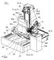
- FIG. 1 is a schematic perspective view showing a machine tool according to a first embodiment.
- FIG. 2 is a schematic perspective view showing a machine tool according to the first embodiment.
- FIG. 3 is a schematic perspective view showing a machine tool according to the first embodiment.
- FIG. 4 is a schematic plan view showing the machine tool in the first embodiment.
- FIG. 5 is a schematic plan view showing a machine tool according to the first embodiment.
- FIG. 6 is a schematic plan view illustrating the machine tool in the first embodiment.
- FIG. 7 is a schematic plan view showing the machine tool in the first embodiment.
- FIG. 8 is a schematic plan view illustrating a machine tool in a first modified example of the first embodiment.
- FIG. 9 is a schematic side view showing a part of the processing head.
- FIG. 1 is a schematic perspective view showing a machine tool according to a first embodiment.
- FIG. 2 is a schematic perspective view showing a machine tool according to the first embodiment.
- FIG. 3 is a schematic perspective view showing
- FIG. 10 is a schematic perspective view illustrating an example of the first robot and the support base.
- FIG. 11 is a schematic perspective view showing an enlarged example of a tool support device attached to a multi-joint arm.
- FIG. 12 is a schematic plan view illustrating the machine tool in the first embodiment.
- FIG. 13 is a schematic plan view illustrating a machine tool in a second modified example of the first embodiment.
- FIG. 14 is a flowchart showing an example of a workpiece machining method in the first embodiment.
- FIG. 15 is a flowchart showing another example of the workpiece machining method in the first embodiment.
- FIG. 16 is a schematic plan view illustrating the machine tool in the first embodiment.
- FIG. 17 is a schematic perspective view showing a machine tool according to the second embodiment.
- FIG. 18 is a schematic side view showing a machining head in a modified example.
- FIG. 19 is a schematic plan view illustrating a machine tool according to the second embodiment.
- FIG. 20 is a schematic perspective view illustrating an example of the second robot and the support base.
- FIG. 21 is a schematic perspective view showing an enlarged example of the second tool support device attached to the second articulated arm.
- FIG. 22 is a schematic plan view illustrating a machine tool system according to the second embodiment.
- FIG. 23 is a schematic plan view illustrating a machine tool according to the second embodiment.
- FIG. 24 is a diagram illustrating a state in which at least one tool changer is capable of changing a first rotating tool supported by a machining head to another first rotating tool.
- FIG. 25 is a diagram illustrating a state in which at least one tool changer is capable of replacing a second rotating tool supported by the tool support device of the first robot with another second rotating tool.
- FIG. 26 is a diagram illustrating a state in which at least one tool changer is capable of replacing a third rotating tool supported by a second tool support device of a second robot with another third rotating tool.
- FIG. 27 is a schematic perspective view showing a machine tool according to the second embodiment.
- FIG. 28 is a schematic perspective view illustrating a machine tool according to the second embodiment.
- FIG. 29 is a diagram illustrating a schematic diagram of a state in which a control device is capable of controlling a plurality of control target devices.
- FIG. 30 is an enlarged schematic perspective view showing a state in which one step of the workpiece machining method is being performed.
- FIG. 31 is an enlarged schematic perspective view showing a state in which one step of the workpiece machining method is being performed.
- FIG. 32 is an enlarged schematic perspective view showing a state in which one step of the workpiece machining method is being performed.
- FIG. 33 is an enlarged schematic perspective view showing a state in which one step of the workpiece machining method is being performed.
- FIG. 34 is an enlarged schematic perspective view showing a state in which one step of the workpiece machining method is being performed.
- FIG. 35 is an enlarged schematic perspective view showing a state in which one step of the workpiece machining method is being performed.
- FIG. 36 is an enlarged schematic perspective view showing a state in which one step of the workpiece machining method is being performed.
- FIG. 37 is a flowchart showing an example of a workpiece machining method in the second embodiment.
- FIG. 38 is a flowchart showing another example of the workpiece machining method in the second embodiment.
- FIG. 39 is a schematic front view showing an enlarged portion of the movable wall.
- FIG. 40 is a schematic plan view illustrating an example of the arrangement relationship between the first processing device and the first robot.
- FIG. 41 is a schematic plan view showing an example of the arrangement relationship between the first processing device and the first robot.
- FIG. 42 is a schematic plan view showing an example of the arrangement relationship between the first processing device, the first robot, and the second robot.
- FIG. 43 is a schematic plan view showing an example of the arrangement relationship between the first processing device, the first robot, and the second robot.
- FIG. 44 is a schematic plan view illustrating an example of the arrangement relationship between the first processing device and the
- the machining head 30 of the first machining device 3 can support a rotating tool.
- the rotating tools supported by the machining head 30 are collectively referred to as a first rotating tool.
- a plurality of rotating tools sequentially supported by the machining head 30 are referred to as a first group of rotating tools.
- the articulated arm 50 of the first robot 5 is capable of supporting a rotating tool.
- the rotating tools supported by the articulated arm 50 are collectively referred to as a second rotating tool.
- the multiple rotating tools supported in sequence by the articulated arm 50 are referred to as a second group of rotating tools.
- the second multi-joint arm 60 of the second robot 6 is capable of supporting a rotating tool.
- the rotating tools supported by the second multi-joint arm 60 are collectively referred to as a third rotating tool.
- the multiple rotating tools supported in sequence by the second multi-joint arm 60 are referred to as a third group of rotating tools.
- the direction from the first processing device 3 toward the workpiece supporting device 2 in a plan view (more specifically, the direction from the first processing device 3 toward the table device 20 in a plan view) is defined as a first direction DR1.
- the direction from the first support table 25a toward the second support table 25b is defined as a second direction DR2.
- the second direction DR2 is perpendicular to the first direction DR1.
- the first machining device 3 has a machining head 30 and a plurality of linear motion devices 4.
- the machining head 30 can support a first rotating tool T1 that machines a workpiece W supported by a table 21.
- the work support device 2 has a first drive device 23 (e.g., a motor) that rotates the table 21 around the first axis AX1. It is preferable that the first drive device 23 can rotate the table 21 360 degrees around the first axis AX1.
- a first drive device 23 e.g., a motor
- the first drive device 23 can rotate the table 21 360 degrees around the first axis AX1.
- the workpiece W has a first main surface Wa, a second main surface Wb, a first side surface Wc (e.g., a left side surface), and a second side surface Wd (e.g., a right side surface).
- the first robot 5 can process the first side surface Wc of the workpiece W (see FIG. 40 if necessary).
- the first processing device 3 can process the second main surface Wb located on the opposite side of the first main surface Wa.
- the table 21 is rotated from the state shown in FIG.
- the first robot 5 can process the second side surface Wd located on the opposite side of the first side surface Wc.
- the machine tool 1A can sequentially simultaneously machine the workpiece W supported on the table 21 by the first processing device 3 and the first robot 5, rotate the table 21 supporting the workpiece W about the first axis AX1 by a predetermined angle (the predetermined angle is, for example, 45 degrees, 90 degrees, 180 degrees, etc.), and again simultaneously machine the workpiece W supported on the table 21 by the first processing device 3 and the first robot 5.
- the workpiece W machined by the machine tool 1 is, for example, a metal workpiece.
- the term "machine tool” in this specification can be read as "metal processing device.”
- the workpiece W machined by the machine tool 1 may be an aluminum workpiece.
- the workpiece W machined by the machine tool 1 may be an aluminum cast part.
- the workpiece W machined by the machine tool 1 may be an automobile part or other workpiece.
- the workpiece W may be a part of the body frame of an automobile.
- the workpiece W machined by the machine tool 1 may be a small workpiece or a large workpiece.
- the height of the workpiece W (more specifically, the distance from the bottom surface to the top surface We of the workpiece W) may be, for example, 1000 mm or more, or 1500 mm or more.
- the workpiece supporting device 2 includes a table 21, a block 22 that supports the table 21 so as to be rotatable about a first axis AX1, and a first drive device 23 that rotates the table 21 about the first axis AX1.
- Each of the table 21 and the block 22 may be formed of a single part, or may be formed of an assembly of multiple parts.
- the first axis AX1 is substantially perpendicular to a horizontal plane.
- the first axis AX1 may be inclined with respect to the horizontal plane.
- the first axis AX1 may be substantially parallel to the horizontal plane.
- the table 21 and the first drive device 23 are included in the table device 20.
- the machine tool 1A (more specifically, the work support device 2) has a table device 20, which has the table 21 and a first drive device 23 that rotates the table 21 around the first axis AX1.
- the table device 20 may include a block 22 that supports the table 21 so that it can rotate.
- the machine tool 1A may have a guide rail 24 that supports the table device 20 so that it can move in the first direction DR1.
- the machine tool 1A has a third drive device 18 (e.g., a motor) that moves the table device 20, which includes the table 21 and the first drive device 23, in a direction parallel to the first direction DR1.
- the third drive device 18 moves the table device 20 along the guide rails 24.
- the table device 20 can move in a direction parallel to the first direction DR1 at least between an advance position P2 and a retract position P3.
- the advance position P2 is a position where the workpiece W supported by the table 21 can be processed using the first processing device 3.
- the retract position P3 is a position where the workpiece W supported by the table 21 can be rotated around the first axis AX1 without interfering with the first processing device 3 (or the movable wall 11b described below) (see FIG. 6).
- the retract position P3 is located on the first direction DR1 side of the advance position P2.
- the table 21 can be rotated around the first axis AX1 while a large workpiece W is supported on the table 21.
- the machine tool 1A may include a fourth drive device 19d (e.g., a motor) that moves the first processing device 3 in a direction parallel to the first direction DR1.
- the fourth drive device 19d moves the entire first processing device 3, or a structure including the column 38c that supports the processing head 30, in a direction parallel to the first direction DR1.
- the machine tool 1A may include a guide rail 19r that extends in a direction parallel to the first direction DR1.
- the guide rail 19r guides the movement of the entire first processing device 3, or a structure including the column 38c that supports the processing head 30.
- the first processing device 3 can move in a direction parallel to the first direction DR1 between an advance position P4 and a retreat position P5.
- the advance position P4 is a position where the first processing device 3 can be used to process the workpiece W supported by the table 21.
- the retreat position P5 is a position where the workpiece W supported by the table 21 can be rotated around the first axis AX1 without interfering with the first processing device 3 (or the movable wall 11b described below).
- the table 21 can be rotated around the first axis AX1 while a large workpiece W is supported on the table 21.
- the spindle 31 can hold a first rotating tool T1.
- the spindle 31 can rotate around a first rotation axis AD1.
- the first rotation axis AD1 is not parallel to the vertical direction, and more specifically, the first rotation axis AD1 is substantially perpendicular to the vertical direction. In this case, chips generated when the first rotating tool T1 rotating around the first rotation axis AD1 comes into contact with the workpiece W are likely to be discharged downward.
- the first axis AX1 (in other words, the rotation axis of the table 21) is disposed substantially perpendicular to the direction parallel to the first rotation axis AD1.
- the surface to be machined of the workpiece W can be directed toward the first rotating tool T1.
- each surface to be machined of the workpiece W that is parallel to the first axis AX1 can be directly faced with the first rotation axis AD1.
- the table 21 may be tiltable so that the first axis AX1 is substantially perpendicular to the direction parallel to the first rotation axis AD1 (see FIG. 17, if necessary). In this case, too, by rotating the table 21 to each index position about the first axis AX1, each surface to be machined of the workpiece W that is parallel to the first axis AX1 can be made to face the first rotation axis AD1. In addition, if the table 21 is tiltable about a second axis AX2 that is different from the first axis AX1 (see FIG.
- the first robot 5 has a multi-joint arm 50, which has at least six rotation axes (RX1, RX2, RX3, RX4, RX5, RX6). More specifically, the multi-joint arm 50 has a first portion 51a that can rotate around a first rotation axis RX1 with respect to the support base 13a, a second portion 51b that can tilt around a first tilt axis RX2 with respect to the first portion 51a, a third portion 51c that can tilt around a second tilt axis RX3 with respect to the second portion 51b, a fourth portion 51d that can rotate around a second rotation axis RX4 with respect to the third portion 51c, a fifth portion 51e that can tilt around a third tilt axis RX5 with respect to the fourth portion 51d, and a sixth portion 51f that can rotate around a third rotation axis RX6 with respect to the fifth portion 51e.
- the articulated arm 50 has at least three tilt
- the wrist 52 is disposed at the tip of the articulated arm 50.
- the first robot 5 has a wrist 52 disposed at the tip of the articulated arm 50.
- the wrist 52 is composed of the sixth portion 51f described above. The first robot 5 can freely change the position and orientation of the wrist 52.
- the first robot 5 has multiple arm drive devices (e.g., multiple motors MT) that move the multiple joints of the articulated arm 50.
- multiple arm drive devices e.g., multiple motors MT
- the first robot 5 has a tool support device 53 attached to the articulated arm 50 (more specifically, the wrist 52).
- the tool support device 53 is capable of supporting a second rotating tool T2.
- the tool support device 53 has a second rotation drive device 54 (more specifically, a motor) that rotates the second rotating tool T2 around the second rotation axis AD2.
- a second rotation drive device 54 (more specifically, a motor) that rotates the second rotating tool T2 around the second rotation axis AD2.
- the tool support device 53 has a fixed part 56 attached to the articulated arm 50 (more specifically, the wrist 52) and a movable part 57 that is linearly movable relative to the fixed part 56 in a direction parallel to the second rotation axis AD2.
- the fixed part 56 may have a linear guide 56r that guides the movement of the movable part 57 in the direction parallel to the second rotation axis AD2.
- the second rotating tool T2 is attached to a spindle disposed on the movable part 57.
- the tool support device 53 has a tool moving device (hereinafter referred to as the "tool linear motion device 55") that moves the second rotating tool T2 in a direction parallel to the second rotation axis AD2.
- the tool linear motion device 55 has a motor, an electric cylinder, etc. as a drive source.
- the tool linear motion device 55 has a linear guide 56r that guides the movement of the movable part 57 of the tool support device 53 relative to the fixed part 56 of the tool support device 53.
- the tool linear motion device 55 may include a ball screw, a rack and pinion, etc.
- the second rotating tool T2 can be moved in a direction parallel to the second rotation axis AD2 while rotating the second rotating tool T2 around the second rotation axis AD2. Therefore, after the second rotating tool T2 comes into contact with the workpiece W, the hole HL can be formed in the workpiece W using the second rotating tool T2 without changing the position of the wrist 52. This maintains the accuracy of the machining for forming the hole in the workpiece W. In other words, although a decrease in machining accuracy due to the presence of multiple joints in the first robot 5 is unavoidable, an excessive decrease in machining accuracy is prevented because the machining for forming the hole in the workpiece W is performed with the angle of the multiple joints fixed.
- the machine tool 1A has a support base 13a that supports the first robot 5.
- the height of the upper surface 131a of the support base 13a is higher than the height of the upper surface of the table 21.
- the height of the upper surface 131a of the support base 13a is higher than the height of the uppermost end of the table device 20.
- the support base 13a is not movable relative to the base 10 of the machine tool 1A.
- the support base 13a may be movable relative to the base 10 of the machine tool 1A.
- the entire first robot 5 may be movable relative to the base 10.
- the machine tool 1A includes a machining chamber CB defined by a wall 11, and a coolant liquid supply device 91.
- the machining chamber CB is hatched with dots to make it easier to visually recognize the machining chamber CB.
- the machine tool 1A has a wall 11 that defines a machining chamber CB, in which the machining head 30 and the articulated arm 50 of the first robot 5 are disposed.
- a part of the wall 11 (more specifically, a movable wall 11b that is part of the wall 11) is a partition wall that separates the machining chamber CB from a second chamber CD in which all or most of the multiple linear motion devices 4 that move the machining head 30 in three dimensions are disposed.
- the wall 11 defining the machining chamber CB has a fixed wall 11a and a movable wall 11b.
- the movable wall 11b moves in response to the movement of the machining head 30.
- the movable wall 11b may include a first movable wall 11b-1 that expands and contracts in response to the movement of the processing head 30 in a direction parallel to the vertical direction, and a second movable wall 11b-2 that expands and contracts in response to the movement of the processing head 30 in a direction parallel to the horizontal plane.
- the coolant supplying device 91 supplies coolant toward the workpiece W supported by the table 21.
- the coolant supplying device 91 preferably has an injection nozzle 91n that injects coolant.
- the injection nozzle 91n is disposed in the machining head 30.
- the first robot 5 may have the injection nozzle 91n.
- the injection nozzle 91n may be disposed in the ceiling part, etc., of the machine tool 1A.
- the machine tool 1A has a coolant supply device 91, excessive temperature rise of the tool caused by frictional heat is suppressed, and the lubrication characteristics between the workpiece W and the rotating tool are improved. Furthermore, chips are prevented from remaining on the workpiece W.
- coolant can be supplied to the workpiece W, it is also possible to perform heavy cutting of a metal workpiece W using the first machining device 3.
- the articulated arm of a robot is not placed inside the machining chamber where coolant splashes.
- the articulated arm 50 of the first robot 5 is placed inside the machining chamber CB where coolant splashes. If the articulated arm 50 is incompatible with the coolant, a part of the articulated arm 50 (e.g., the joint portion of the articulated arm 50) or substantially the entire articulated arm 50 may be covered with a flexible cover.
- the workpiece passage opening OP is blocked by the door 12. This prevents the coolant liquid supplied to the workpiece W from leaking outside the machine tool 1A through the workpiece passage opening OP.
- a workpiece passage opening OP through which the workpiece W passes is formed in the wall 11 that defines the machining chamber CB.
- the workpiece passage opening OP is formed in the fixed wall 11a.
- the work support device 2 (more specifically, the table device 20) is disposed between the first processing device 3 and the work passage opening OP. Therefore, the first processing device 3 does not get in the way when the work W is loaded or unloaded. For example, when the work W is loaded or unloaded, the work W is prevented from colliding with the first processing device 3, and damage to the first processing device 3 due to the collision is prevented.
- Control device 7 In the example shown in Fig. 4, the machine tool 1A has a control device 7.
- the control device 7 may be configured by one computer or may be configured by multiple computers.
- the machine tool 1A may have a first computer that controls the first processing device 3 and the workpiece support device 2, and a second computer that controls the first robot 5.
- the first computer and the second computer communicate with each other, and the first computer and the second computer work together to function as the control device 7 of the machine tool 1A.
- the workpiece machining method in the first embodiment may be performed using the machine tool 1A in the first embodiment, or may be performed using another machine tool 1A.
- the workpiece W is attached directly or indirectly to the table 21 of the workpiece support device 2.
- the first step ST1 is an attachment process.
- the workpiece W is attached to the table 21 of the workpiece support device 2 via a jig J.
- the jig J may have a chuck J1 (e.g., a hydraulic chuck or an electric chuck) that fixes the workpiece W to the jig J.
- the jig J is fixed to the table 21, and the workpiece W is fixed to the jig J.
- the second step ST2 it is determined whether or not it is necessary to change the posture of the workpiece W (see FIG. 14).
- the second step ST2 is the first judgment process.
- the first judgment process is performed by the control device 7. More specifically, the control device 7 determines whether or not it is necessary to change the posture of the workpiece W based on the machining program stored in the memory 72.
- first judgment step if the control device 7 determines that it is necessary to change the posture of the workpiece W, the workpiece W is rotated around the first axis AX1 (more specifically, the table 21 supporting the workpiece W is rotated around the first axis AX1).
- the table 21 supporting the workpiece W is rotated around the first axis AX1 (rotation step: third step ST3).
- the rotation step (in other words, rotating the table 21 supporting the workpiece W around the first axis AX1) is performed using the first drive device 23 of the workpiece support device 2.
- the first drive device 23 rotates the table 21 supporting the workpiece W around the first axis AX1.
- the turning process (third step ST3) may be performed in combination with a moving process that moves the table device 20. More specifically, when the control device 7 determines that both linear movement of the workpiece W and turning of the workpiece W are necessary, the table device 20 is moved linearly and the table 21 is turned around the first axis AX1.
- the table device 20 is moved linearly from the receiving position P1 to the advancing position P2, and the orientation of the workpiece W is changed from the orientation of the workpiece W at the receiving position P1 to an orientation of the workpiece W suitable for the initial stage of workpiece processing.
- the table device 20 is moved linearly from the receiving position P1 to the advancing position P2, and the rotation angle of the table 21 about the first axis AX1 is maintained.
- control device 7 determines that it is not necessary to change the posture of the workpiece W (second step ST2: No), or if the posture change of the workpiece W has been completed (completion of third step ST3), proceed to fourth step ST4 and fifth step ST5.
- the workpiece W supported by the table 21 is machined using a first group of rotating tools (T1-1, T1-2) supported in sequence by the machining head 30.
- the fourth step ST4 is the first machining process.
- the first group of rotating tools includes a first rotating tool T1-1 (e.g., a milling tool) and another first rotating tool T1-2 (e.g., a drill or a tap tool).
- the first rotating tool T1-1 supported by the machining head 30 is replaced with the other first rotating tool T1-1 by using, for example, a first tool changer 80a (see FIG. 24, if necessary).
- the first machining step includes moving the machining head 30 using multiple linear motion devices 4 while one of the first group of rotating tools is in contact with the workpiece W supported by the table 21.
- machining of the workpiece W is performed by moving the machining head 30 using multiple linear motion devices 4, machining of the workpiece W can be performed with high precision.
- the angular position of the table 21 around the first axis AX1 is fixed.
- the workpiece W supported by the table 21 is machined using the second group of rotating tools (T2-1, T2-2) supported in sequence by the articulated arm 50.
- the fifth step ST5 is the second machining process.
- the workpiece W is being machined using the second group of rotating tools (in other words, when any of the second group of rotating tools is in contact with the workpiece W)
- it is preferable that the angular position of the table 21 around the first axis AX1 is fixed.
- the second group of rotating tools includes a second rotating tool T2-1 (e.g., a first drill) and another second rotating tool T2-2 (e.g., a second drill or a tapping tool).
- a second rotating tool T2-1 e.g., a first drill
- another second rotating tool T2-2 e.g., a second drill or a tapping tool.
- Replacing the second rotating tool T2-1 supported by the articulated arm 50 with the other second rotating tool T2-2 is performed, for example, by using the first tool changing device or a second tool changing device different from the first tool changing device.
- the second machining process may include a tool support device 53 attached to an articulated arm 50 moving a second rotating tool T2, which rotates around the second rotation axis AD2, in a direction parallel to the second rotation axis AD2 using a tool linear motion device 55.
- the second rotating tool T2 is moved using the tool linear motion device 55, the second rotating tool T2 can be moved with high precision.
- a part of the first processing step (fourth step ST4) and a part of the second processing step (fifth step ST5) may be performed simultaneously.
- a part of the first processing step (fourth step ST4) may be performed when the second processing step is not being performed.
- a part of the second processing step (fifth step ST5) may be performed when the first processing step is not being performed.
- the sixth step ST6 it is determined whether or not the processing of the workpiece W has been completed.
- the sixth step ST6 is a second determination step.
- the second determination step is performed by the control device 7. More specifically, the control device 7 determines whether or not the processing of the workpiece W has been completed based on the processing program stored in the memory 72.
- the control device 7 determines whether or not it is necessary to change the posture of the workpiece W (more specifically, it determines whether or not it is necessary to rotate the workpiece W about the first axis AX1). More specifically, the control device 7 determines whether or not it is necessary to rotate the workpiece W about the first axis AX1 based on the machining program stored in the memory 72.
- step ST2 if the control device 7 determines that it is necessary to rotate the workpiece W around the first axis AX1 (second step ST2: Yes), in the third step ST3, the workpiece W is rotated around the first axis AX1 (rotation process).
- the turning process includes turning the table 21 supporting the workpiece W around the first axis AX1.
- the process of turning the table 21 supporting the workpiece W around the first axis AX1 is performed using the first drive device 23 of the workpiece support device 2.
- the first drive device 23 turns the table 21 supporting the workpiece W around the first axis AX1.
- the first machining process (fourth step ST4) and the fifth machining process (fifth step ST5) are performed again.
- the process of moving the workpiece to the removal position includes moving the table device 20 from the advance position P2 to the removal position P6.
- the removal position P6 may be the same position as the receiving position P1 (see FIG. 4) or may be a position different from the receiving position P1.
- the process of moving the workpiece to the removal position may include changing the orientation of the workpiece W.
- the process of moving the workpiece to the removal position includes rotating the workpiece W about the first axis AX1.
- the table 21 supporting the workpiece W is rotated about the first axis AX1 at a position between the advance position P2 and the removal position P6 (more specifically, at the retreat position P3).
- the eighth step ST8 is a removal process.
- the removal process may include moving the door 12 from the closed position to the open position, and moving the workpiece W from the processing chamber CB to outside the processing chamber CB so as to cross the workpiece passage opening OP.
- a part of the first machining step (fourth step ST4) and a part of the second machining step (fifth step ST5) are performed simultaneously, and then the table 21 supporting the workpiece W is rotated around the first axis AX1.
- a part of the process of machining the workpiece W supported by the table 21 using the first group of rotating tools supported in sequence by the machining head 30 and a part of the process of machining the workpiece W supported by the table 21 using the second group of rotating tools supported in sequence by the articulated arm 50 are performed simultaneously before the execution of one rotation process (in other words, a process of rotating the table 21 supporting the workpiece W).
- a part of the first machining step (fourth step ST4) and a part of the second machining step (fifth step ST5) are executed simultaneously.
- a part of the step of machining the workpiece W supported by the table 21 using the first group of rotating tools supported in sequence by the machining head 30 and a part of the step of machining the workpiece W supported by the table 21 using the second group of rotating tools supported in sequence by the articulated arm 50 are executed simultaneously after execution of the above-mentioned one rotating step (in other words, a step of rotating the table 21 supporting the workpiece W).
- a part of the first machining process and a part of the second machining process are simultaneously performed, so that the workpiece W is machined more efficiently and in a shorter time.
- the workpiece machining method in the first embodiment may include repeatedly executing the machining cycle "N" times or more.
- N is, for example, 1, 2, 3, 4, 5, 6, 7, 8, 9, 10, ....
- a part of the process of machining the workpiece W supported by the table 21 using a first group of rotating tools supported in sequence by the machining head 30 and a part of the process of machining the workpiece W supported by the table 21 using a second group of rotating tools supported in sequence by the articulated arm 50 may be executed simultaneously.
- the first group of rotating tools supported in sequence by the machining head 30 includes a surface machining tool (e.g., a milling tool), and the second group of rotating tools supported in sequence by the articulated arm 50 includes a hole forming tool (e.g., a drill or a tapping tool).
- a surface machining tool e.g., a milling tool
- a hole forming tool e.g., a drill or a tapping tool
- Fig. 17 is a schematic perspective view showing the machine tool 1B in the second embodiment.
- Fig. 18 is a schematic side view showing the machining head 30 in a modified example.
- Fig. 19 is a schematic plan view showing the machine tool 1B in the second embodiment.
- Fig. 20 is a schematic perspective view showing an example of the second robot 6 and the support base 13b.
- Fig. 21 is a schematic perspective view showing an enlarged example of the second tool support device 63 attached to the second articulated arm 60.
- Fig. 22 is a schematic plan view showing the machine tool system 100 in the second embodiment.
- FIG. 23 is a schematic plan view showing the machine tool 1B in the second embodiment.
- Fig. 24 is a diagram showing a state in which at least one tool exchange device 8 can exchange the first rotating tool T1 supported by the machining head 30 for another first rotating tool.
- FIG. 25 is a diagram showing a state where at least one tool exchange device 8 can exchange the second rotating tool T2 supported by the tool support device 53 of the first robot with another second rotating tool.
- FIG. 26 is a diagram showing a state where at least one tool exchange device 8 can exchange the third rotating tool T3 supported by the second tool support device 63 of the second robot with another third rotating tool.
- FIGS. 27 and 28 are schematic perspective views showing a machine tool 1B in the second embodiment.
- FIG. 29 is a diagram showing a state where the control device 7 can control a plurality of control target devices.
- FIGS. 30 to 36 is a schematic perspective view showing an enlarged state where one step of the workpiece machining method is being performed.
- FIG. 37 is a flowchart showing an example of the workpiece machining method in the second embodiment.
- FIG. 38 is a flowchart showing another example of the workpiece machining method in the second embodiment.
- the work support device 2 has a second drive device 26 that tilts the table 21 around the second axis AX2.
- the machine tool 1B in the second embodiment is equipped with a second robot 6.
- the machine tool 1B in the second embodiment includes (1) a workpiece supporting device 2 having a table 21 that supports a workpiece, (2) a first processing device 3 having a processing head 30 capable of supporting a first rotating tool T1 that processes the workpiece supported by the table 21 and a plurality of linear motion devices 4 that move the processing head 30 three-dimensionally, and (3) a first robot 5 having a multi-joint arm 50 that changes the position and orientation of the second rotating tool T2 and that uses the second rotating tool T2 to process the workpiece supported by the table 21.
- the workpiece supporting device 2 also has a first drive device 23 that rotates the table 21 around the first axis AX1.
- the machine tool 1B in the second embodiment has the same effects as the machine tool 1A in the first embodiment.
- the workpiece supporting device 2 has a second driving device 26 (e.g., a motor) that tilts the table 21 around the second axis AX2.
- the second driving device 26 tilts the block 22 around the second axis AX2, thereby tilting the table 21 supported by the block 22 around the second axis AX2.
- the second axis AX2 is an axis different from the first axis AX1. More specifically, the second axis AX2 is perpendicular to the first axis AX1.
- the second axis AX2 may be substantially parallel to a horizontal plane.
- the inclined surface WS of the workpiece W (see FIG. 33, if necessary) can be positioned perpendicular to the first rotation axis AD1 of the first rotating tool T1.
- high-precision machining using the machining head 30 can be applied to the inclined surface WS of the workpiece W. Therefore, it is not necessary to assign precision machining of the inclined surface WS of the workpiece W to a machine tool other than the machine tool 1.
- the inclined surface WS of the workpiece W is a surface inclined with respect to the first axis AX, or a surface inclined with respect to the upper surface of the table 21.
- the work support device 2 (more specifically, the second drive device 26) can tilt the table 21 about the second axis AX2 so that the inclined surface WS of the work W is changed from a position in which it is inclined with respect to the first rotation axis AD1 of the first rotating tool T1 (more specifically, as illustrated in Figure 31, a position in which the inclined surface WS of the work W is inclined with respect to the horizontal plane) to a position in which the inclined surface WS of the work W is substantially perpendicular to the first rotation axis AD1 of the first rotating tool T1 (more specifically, as illustrated in Figure 33, a position in which the inclined surface WS of the work W is substantially perpendicular to the horizontal plane).
- control device 7 executes the machining program stored in the memory 72 to send a tilt command E2 (see FIG. 29, if necessary) to the second driving device 26 so that the inclined surface WS of the workpiece W is changed from a position inclined with respect to the first rotation axis AD1 of the first rotating tool T1 to a position in which the inclined surface WS of the workpiece W is substantially perpendicular to the first rotation axis AD1 of the first rotating tool T1.
- the second driving device 26 which receives the tilt command E2, tilts the table 21 about the second axis AX2 so that the inclined surface WS of the workpiece W is changed to a position in which the inclined surface WS of the workpiece W is substantially perpendicular to the first rotation axis AD1 of the first rotating tool T1.
- the machine tool 1 is configured so that the inclined surface WS of the workpiece W can be machined by the first rotating tool T1 supported by the machining head 30 after the inclined surface WS of the workpiece W is changed to a position substantially perpendicular to the first rotation axis AD1.
- the control device 7 executes the machining program stored in the memory 72 to send a first movement command E3-1 (see FIG. 29, if necessary) to the first linear motion device 41, which is one of the multiple linear motion devices 4, so that the hole forming tool T1-5 (e.g., a tapping tool or a hole drilling tool) rotating around the first rotation axis AD1 moves linearly along the first rotation axis AD1.
- a first movement command E3-1 see FIG. 29, if necessary
- the first linear motion device 41 which receives the first movement command E3-1, moves the hole forming tool T1-5 rotating around the first rotation axis AD1 linearly along the first rotation axis AD1 so that the hole HL is formed in the inclined surface WS of the workpiece W. In this way, the hole HL can be formed with high accuracy in the inclined surface WS of the workpiece W.
- the control device 7 may execute a machining program stored in the memory 72 to send a movement command E3 (see FIG. 29, if necessary) to the multiple linear motion devices 4 so that the surface machining tool T1-6 (e.g., a milling tool) rotating about the first rotation axis AD1 faces the inclined surface WS.
- the multiple linear motion devices 4 that receive the movement command E3 move the surface machining tool rotating about the first rotation axis AD1 in a direction perpendicular to the first rotation axis AD1 so that the inclined surface WS of the workpiece W is face-machined. In this way, the surface machining of the inclined surface WS of the workpiece W is performed with high precision.
- the top surface We of the workpiece W can be tilted with respect to the horizontal plane.
- the second rotating tool T2 supported by the multi-joint arm 50 or the third rotating tool T3 supported by the second multi-joint arm 60 vertically downward to the top surface We of the workpiece W.
- This allows the size of the multi-joint arm 50 of the first robot 5 (or the size of the second multi-joint arm 60 of the second robot 6) to be reduced.
- This allows the multiple surfaces of the workpiece W, including the top surface We, to be efficiently machined without increasing the size of the first robot 5 (or the second robot 6).
- the second drive unit 26 is capable of tilting the table 21 steplessly around the second axis AX2. In other words, it is preferable that the machine tool 1 is capable of adjusting the tilt angle of the table 21 steplessly.
- the second drive unit 26 may be capable of maintaining the angle between the horizontal plane and the top surface of the table 21 at any angle between 0 degrees and 90 degrees.
- the articulated arm 50 can change the orientation of the second rotating tool T2 to any orientation, there is no need to tilt the workpiece W when machining using the first robot 5.
- the movement of the machining head 30 is, in principle, performed using multiple linear motion devices 4, so the orientation of the machining head 30 cannot be changed relative to the workpiece W.
- the machine tool 1B in the second embodiment (or the machine tool 1A in the first embodiment) may be equipped with a tilt drive device 35 that tilts the machining head 30 around the tilt axis AT.
- the tilt drive device 35 there is also a limit to the tilting around the tilt axis AT using the tilt drive device 35.
- at least two tilt axes are required to change the orientation of the machining head 30 to any orientation.
- the machine tool 1B in the second embodiment may have a tilting drive device that tilts the machining head 30 around each of the two tilting axes, but as the machining head 30 is provided with more tilting axes, there is a risk that the accuracy of machining performed using the first machining device 3 will decrease.
- the workpiece support device 2 has a table device 20.
- the table device 20 has a table 21, a block 22 that supports the table 21 so as to be rotatable around the first axis AX1, a first drive device 23 that rotates the table 21 around the first axis AX1, and a support base 25 that supports the block 22 so as to be tiltable around the second axis AX2.
- the table device 20 may have a second drive device 26 that tilts the table 21 around the second axis AX2.
- the first drive device 23 is mounted on the block 22, and the first drive device 23 can tilt together with the block 22 around the second axis AX2.
- the orientation of the first axis AX1 also changes with the tilt of the table 21 around the second axis AX2.
- the second drive unit 26 may be mounted on the block 22 that supports the table 21 so as to be tiltable, and the second drive unit 26 may be configured to be rotatable around the first axis AX1 together with the block 22.
- the orientation of the second axis AX2 may be configured to change with the rotation of the table 21 around the first axis AX1.
- the support base 25 includes a first support base 25a that supports the first end 22a of the block 22 so that it can tilt around the second axis AX2, and a second support base 25b that supports the second end 22b of the block 22 so that it can tilt.
- the table 21 has a generally circular shape with a portion of the circle cut out in a plan view.
- the shape of the table 21 is not limited to the example shown in FIG. 17.
- the shape of the table 21 may be, for example, a polygonal shape.
- the block 22 has a first end 22a tiltably supported by a first support base 25a, a second end 22b tiltably supported by a second support base 25b, and a central portion 22c between the first end 22a and the second end 22b.
- the block 22 also has a concave shape in which the central portion 22c is recessed relative to the first end 22a and the second end 22b.
- the table 21 is disposed directly above the central portion 22c with the top surface of the table 21 arranged parallel to the horizontal plane. In the example shown in FIG. 17, with the top surface of the table 21 arranged parallel to the horizontal plane, the height of the top surface of the table 21 is lower than the height of the second axis AX2.
- the block 22 supporting the table 21 has an elongated shape with the second direction DR2 as the longitudinal direction when viewed in a direction parallel to the first axis AX1. Note that the shape of the block 22 is not limited to the shape shown in FIG. 17 and may be any shape.
- the work support device 2 may have a guide rail 24 that guides the movement of the table device 20 in a direction parallel to the first direction DR1.
- the machine tool 1 may have a third drive device 18 that moves the table device 20 in a direction parallel to the first direction DR1.
- the first direction DR1 is substantially parallel to the horizontal plane and substantially perpendicular to the second axis AX2.
- the machine tool 1 may be provided with a fourth drive unit 19d (see FIG. 8, if necessary) that moves the first processing device 3 in a direction parallel to the first direction DR1.
- the third drive unit 18 and the fourth drive unit 19d have already been described in the first embodiment, so a repeated description of their configuration will be omitted.
- the table device 20 is movable in a direction parallel to the first direction DR1 at least between the receiving position P1 and the advancing position P2.
- the receiving position P1 and the advancing position P2 have already been described in the first embodiment, so a repeated description of these positions will be omitted.
- the table device 20 is movable in a direction parallel to the first direction DR1 at least between the advance position P2 and the retreat position P3.
- the advance position P2 and the retreat position P3 have already been described in the first embodiment, so a repeated description of these positions will be omitted.
- the receiving position P1 is set near the work passage opening OP formed in the wall 11.
- the receiving position P1 is, for example, an end position in the first direction DR1 within the movable range of the table device 20.
- the advance position P2 is, for example, an end position in the opposite direction to the first direction DR1 within the movable range of the table device 20, or a position close to the end position in the opposite direction to the first direction DR1.
- one position is shown as the advance position P2, but there may be multiple advance positions P2.
- the advance position P2 when the work W supported by the table 21 in a tilted state is processed by the first processing device 3 may be set on the first direction DR1 side compared to the advance position P2 when the work W supported by the table 21 in a non-tilted state is processed by the first processing device 3.
- the position of the table device 20 when the workpiece W supported by the tilted table 21 is processed by the first processing device 3 may be set toward the first direction DR1 compared to the position of the table device 20 when the workpiece W supported by the non-tilted table 21 is processed by the first processing device 3 (see the position of the table device 20 in each of Figures 27 and 28).
- the evacuation position P3 is, for example, a predetermined position between the end position of the first direction DR1 of the movable range of the table device 20 and the end position of the movable range of the table device 20 in the opposite direction to the first direction DR1.
- the evacuation position P3 may be the same position as the receiving position P1.
- the machining head 30 has already been described in the first embodiment, and therefore a repeated description of the machining head 30 will be omitted (for the machining head 30, see, for example, FIG. 9 ).
- the first rotation axis AD1 which is the rotation axis of the first rotating tool T1 (in other words, the rotation axis of the spindle 31 of the machining head 30) is substantially perpendicular to the second axis AX2.
- the machine tool 1 includes a second robot 6.
- the second robot 6 uses a third rotating tool T3 to machine a workpiece supported by a table 21.
- the second robot 6 has a second articulated arm 60 that changes the position and orientation of the third rotating tool T3. It can also be said that the second robot 6 is a second articulated robot.
- a work support device 2 e.g., a table device 20, or a guide rail 24 that movably supports the table device 20
- the first robot 5 and the second robot 6 can process the workpiece W from both sides of the workpiece W simultaneously.
- the second robot 6 has a second multi-joint arm 60, which has at least six rotation axes (RT1, RT2, RT3, RT4, RT5, RT6). More specifically, the second articulated arm 60 has a first part 61a that can rotate around a first rotation axis RT1 with respect to the support base 13b, a second part 61b that can tilt around a first tilt axis RT2 with respect to the first part 61a, a third part 61c that can tilt around a second tilt axis RT3 with respect to the second part 61b, a fourth part 61d that can rotate around a second rotation axis RT4 with respect to the third part 61c, a fifth part 61e that can tilt around a third tilt axis RT5 with respect to the fourth part 61d, and a sixth part 61f that can rotate around a third rotation axis RT6 with respect to the fifth part 61e.
- the second wrist 62 is disposed at the tip of the second multi-joint arm 60.
- the second robot 6 has a second wrist 62 disposed at the tip of the second multi-joint arm 60.
- the second wrist 62 is composed of the sixth portion 61f described above. The second robot 6 can freely change the position and orientation of the second wrist 62.
- the second robot 6 has multiple arm drive devices (e.g., multiple motors MT) that move the multiple joints of the second articulated arm 60.
- multiple arm drive devices e.g., multiple motors MT
- the second robot 6 has a second tool support device 63 attached to the second articulated arm 60 (more specifically, the second wrist 62).
- the second tool support device 63 is capable of supporting a third rotating tool T3.
- the second tool support device 63 has a third rotation drive device 64 (more specifically, a motor) that rotates the third rotating tool T3 around the third rotation axis AD3.
- a third rotation drive device 64 (more specifically, a motor) that rotates the third rotating tool T3 around the third rotation axis AD3.
- the second tool support device 63 has a fixed part 66 attached to the second articulated arm 60 (more specifically, the second wrist 62) and a movable part 67 that is linearly movable relative to the fixed part 66 in a direction parallel to the third rotation axis AD3.
- the fixed part 66 may have a linear guide 66r that guides the movement of the movable part 67 in the direction parallel to the third rotation axis AD3.
- the third rotating tool T3 is attached to a spindle disposed on the movable part 67.
- the second tool support device 63 has a tool moving device (hereinafter referred to as the "second tool linear motion device 65") that moves the third rotating tool T3 in a direction parallel to the third rotation axis AD3.
- the second tool linear motion device 65 has a motor, an electric cylinder, or the like as a driving source.
- the second tool linear motion device 65 has a linear guide 66r that guides the movement of the movable part 67 of the second tool support device 63 relative to the fixed part 66 of the second tool support device 63.
- the second tool linear motion device 65 may include a ball screw, a rack and pinion, or the like.
- the third rotating tool T3 can be moved in a direction parallel to the third rotation axis AD3 while rotating the third rotating tool T3 around the third rotation axis AD3. Therefore, after the third rotating tool T3 comes into contact with the workpiece W, the hole HL can be formed in the workpiece W using the third rotating tool T3 without changing the position of the second wrist 62. This maintains the accuracy of the machining for forming the hole in the workpiece W.
- the machine tool 1 has a support base 13b that supports the second robot 6.
- the height of the upper surface 131b of the support base 13b is higher than the height of the upper surface of the table 21.
- the height of the upper surface 131b of the support base 13b is higher than the height of the uppermost end of the table device 20.
- the support base 13b cannot move relative to the base 10 of the machine tool 1.
- the support base 13b may be movable relative to the base 10 of the machine tool 1.
- the entire second robot 6 may be movable relative to the base 10.
- the machine tool system 100 in the second embodiment includes a machine tool 1 (e.g., the machine tool 1A in the first embodiment, or the machine tool 1B in the second embodiment) and a third robot 101 arranged outside the machine tool 1.
- a machine tool 1 e.g., the machine tool 1A in the first embodiment, or the machine tool 1B in the second embodiment
- a third robot 101 arranged outside the machine tool 1.
- the third robot 101 carries the workpiece W from outside the machine tool 1 into the machining chamber CB, and/or carries the workpiece from the table 21 to outside the machining chamber CB (i.e., carries the machined workpiece).
- a wall 11 (more specifically, a fixed wall 11a) that defines the machining chamber CB is disposed between the third robot 101 and the first robot 5.
- the number of robots for carrying in and out the workpiece is not limited to one. In other words, the machine tool system 100 may have other robots for carrying in and out the workpiece in addition to the third robot 101.
- the third robot 101 carries the workpiece W from outside the machine tool 1 into the machining chamber CB of the machine tool 1 through the workpiece passage opening OP. More specifically, the third robot 101 carries the workpiece W from outside the machine tool 1 into the machining chamber CB of the machine tool 1 through the workpiece passage opening OP, and the table device 20 (more specifically, the table 21) receives the workpiece W from the third robot 101. When the table device 20 is located at the receiving position P1, the table device 20 can smoothly receive the workpiece W from the third robot 101.
- the third robot 101 has a third multi-joint arm 102, which can cross the workpiece passage opening OP.
- the third robot 101 also has a gripper 103 capable of gripping the workpiece W.
- the gripper 103 is attached, for example, to the tip of the third multi-joint arm 102.
- the machine tool 1 includes a wall 11 that defines a machining chamber CB.
- a machining head 30, a multi-joint arm 50 of a first robot 5, and a second multi-joint arm 60 of a second robot 6 are arranged in the machining chamber CB.
- the wall 11 includes a first wall 11-1 and a second wall 11-2.
- the first wall 11-1 separates the machining chamber CB from the second chamber CD in which all or most of the multiple linear motion devices 4 that move the machining head 30 in three dimensions are disposed.
- the first wall 11-1 also includes a movable wall 11b.
- a workpiece passage opening OP is formed in the second wall 11-2.
- the second wall 11-2 is disposed opposite the first wall 11-1.
- the wall 11 defining the processing chamber CB has a third wall 11-3 that connects one side of the first wall 11-1 to one side of the second wall 11-2, and a fourth wall 11-4 that faces the third wall 11-3.
- the wall 11 defining the processing chamber CB includes a movable wall 11b that moves in response to the movement of the processing head 30.
- the movable wall 11b may include a first movable wall 11b-1 that expands and contracts in response to the movement of the processing head 30 in a direction parallel to the vertical direction, and a second movable wall 11b-2 that expands and contracts in response to the movement of the processing head 30 in a direction parallel to the horizontal plane.
- the machine tool 1 includes a coolant supplying device 91 that supplies coolant toward the workpiece W supported by the table 21.
- the coolant supplying device 91 has been described in the first embodiment, and therefore a repeated description of the coolant supplying device 91 will be omitted.
- (Work passage opening OP, door 12) 23 a workpiece passage opening OP through which the workpiece W passes is formed in a wall 11 that defines the machining chamber CB.
- the machine tool 1 also includes a door 12 that opens and closes the workpiece passage opening OP formed in the wall 11.
- the work support device 2 is disposed between the first processing device 3 and the work passage opening OP in a plan view. Therefore, the first processing device 3 does not get in the way when the work W is being loaded or unloaded.
- the work passage opening OP, the first robot 5, the first processing device 3, and the second robot 6 are arranged around the work support device 2 (more specifically, the table device 20) in a plan view. More specifically, the work passage opening OP, the first robot 5, the first processing device 3, and the second robot 6 are arranged around the work support device 2 with the work support device 2 at the center in a plan view. In this case, the size of the machine tool 1 in a plan view can be made compact.
- the first processing device 3 has a moving body that three-dimensionally moves the processing head 30. More specifically, the first processing device 3 has a first moving body 36, a second moving body 37, and a third moving body 38.
- the first moving body 36 is movable together with the machining head 30 in a direction parallel to the Y axis.
- the first moving body 36 supports the machining head 30 and is movable in a direction parallel to the Y axis.
- the Y axis is, for example, substantially parallel to the first rotation axis AD1, which is the rotation axis of the first rotating tool T1.
- the Y axis may also be substantially parallel to the first direction DR1.
- the second moving body 37 can move together with the machining head 30 in a direction parallel to the Z axis.
- the second moving body 37 supports the machining head 30 via the first moving body 36 and can move in a direction parallel to the Z axis.
- the Z axis is substantially parallel to the vertical direction.
- the machine tool 1 has a base 10, which supports the third movable body 38 so that it can move in a direction parallel to the X-axis.
- the machine tool 1 (more specifically, the first machining device 3) has a plurality of linear motion devices 4 that move the machining head 30 three-dimensionally.
- the plurality of linear motion devices 4 also include a first linear motion device 41, a second linear motion device 44, and a third linear motion device 47.
- the first linear motion device 41 moves the machining head 30 in a direction parallel to the Y-axis.
- the second linear motion device 44 moves the machining head 30 in a direction parallel to the Z-axis.
- the third linear motion device 47 moves the machining head 30 in a direction parallel to the X-axis.
- the first linear motion device 41 has a drive device 42 (e.g., a motor) that moves the first moving body 36 in a direction parallel to the Y axis.
- the first linear motion device 41 preferably has a first linear guide 43 that guides the movement of the first moving body 36 in a direction parallel to the Y axis.
- the first linear guide 43 is disposed on the second moving body 37.
- the second linear motion device 44 has a drive device 45 (e.g., a motor) that moves the second moving body 37 in a direction parallel to the Z axis.
- the second linear motion device 44 preferably has a second linear guide 46 that guides the movement of the second moving body 37 in a direction parallel to the Z axis.
- the second linear guide 46 is disposed on the third moving body 38.
- the third linear motion device 47 has a drive device 48 (e.g., a motor) that moves the third moving body 38 in a direction parallel to the X-axis.
- the third linear motion device 47 preferably has a third linear guide 49 that guides the movement of the third moving body 38 in a direction parallel to the X-axis.
- the third linear guide 49 supports the third moving body 38 so that it can move.
- the third linear guide 49 is also disposed on the base 10 of the machine tool 1.
- the machine tool 1 preferably includes at least one tool exchange device 8.
- the at least one tool exchange device 8 is disposed at an arbitrary position of the machine tool 1.
- the at least one tool exchange device 8 is capable of exchanging the first rotating tool T1 held by the machining head 30 with another first rotating tool.
- the at least one tool exchange device 8 is capable of exchanging the second rotating tool T2 supported by the articulated arm 50 of the first robot 5 with another second rotating tool.
- the at least one tool exchange device 8 is capable of exchanging the third rotating tool T3 supported by the second articulated arm 60 of the second robot 6 with another third rotating tool.
- At least one tool exchange device 8 includes a first tool exchange device 80a.
- the first tool exchange device 80a exchanges the first rotating tool T1-1 held in the machining head 30 with another first rotating tool T1-2.
- the first tool exchange device 80a exchanges the first rotating tool T1-1 held in the machining head 30 with another first rotating tool T1-2 taken out from at least one tool stocker 93.
- the first tool changer 80a has a first gripping portion 82a capable of gripping a first rotating tool T1-1 and a second gripping portion 83a capable of gripping another first rotating tool T1-2.
- the first tool change device 80a may have a tool change arm 81a, an arm rotation device 84a that rotates the tool change arm 81a, and an arm movement device 85a that linearly moves the tool change arm 81a.
- the machining head 30 may be configured to access the tool stocker 93 and directly replace the first rotating tool T1 held in the machining head 30 with another first rotating tool.
- a tool exchange device that performs tool exchange for the machining head 30 is omitted.
- At least one tool change device 8 includes a second tool change device 80b.
- the second tool change device 80b changes the second rotating tool T2-1 supported on the articulated arm 50 via the tool support device 53 to another second rotating tool T2-2.
- the second tool change device 80b may change the second rotating tool T2-1 supported on the articulated arm 50 via the tool support device 53 to another second rotating tool T2-2 taken out from at least one tool stocker 93.
- each second rotating tool T2 is a tool that cannot be attached to the machining head 30 of the first machining device 3
- each first rotating tool T1 is a tool that cannot be attached to the tool support device 53 of the first robot 5.
- the tool support device 53 may be configured to access the tool stocker 93 and directly replace the second rotating tool T2 supported by the tool support device 53 with another second rotating tool.
- a tool exchange device that performs tool exchange for the tool support device 53 is omitted.
- At least one tool changer 8 changes the third rotating tool T3-1 supported by the second articulated arm 60 via the second tool support device 63 to another third rotating tool T3-2. As illustrated in FIG. 26, at least one tool changer 8 may change the third rotating tool T3-1 supported by the second articulated arm 60 via the second tool support device 63 to another third rotating tool T3-2 taken out from at least one tool stocker 93.
- each third rotating tool T3 is a tool that cannot be attached to the machining head 30 of the first machining device 3
- each first rotating tool T1 is a tool that cannot be attached to the second tool support device 63 of the second robot 6.
- the second tool support device 63 may be configured to access the tool stocker 93 and directly replace the third rotating tool T3 supported by the second tool support device 63 with another third rotating tool. In this case, a tool changer that changes tools for the second tool support device 63 is omitted.
- table 21 is in a non-tilting state
- first axis AX1 is substantially perpendicular to a horizontal plane.
- table 21 is a table that does not rotate around first axis AX1
- table 21 is in a non-tilting state refers to a state in which the top surface of the table is substantially parallel to a horizontal plane.
- the first processing device 3 and the first robot 5 can simultaneously process the workpiece W supported by the table 21 in a non-tilting state.
- the first processing device 3 and the first robot 5 can simultaneously process the workpiece W supported by the table 21.
- the first processing device 3, the first robot 5, and the second robot 6 can simultaneously process the workpiece W supported by the table 21 in a non-tilted state.
- the first processing device 3, the first robot 5, and the second robot 6 can simultaneously process the workpiece W supported by the table 21.
- table 21 is in a tilted state
- a tilted state refers to a state in which the first axis AX1 is not parallel to the vertical direction.
- table 21 is in a tilted state
- a tilted state refers to a state in which the top surface of the table is inclined with respect to the horizontal plane.
- the first processing device 3 and the first robot 5 can simultaneously process the workpiece W supported by the tilted table 21.
- the first processing device 3 and the first robot 5 can simultaneously process the workpiece W supported by the table 21.
- the first processing device 3, the first robot 5, and the second robot 6 can simultaneously process the workpiece W supported by the tilted table 21.
- the first processing device 3, the first robot 5, and the second robot 6 can simultaneously process the workpiece W supported by the table 21.
- Control device 7 In the example shown in FIG. 19, the control device 7 controls the workpiece support device 2, the first processing device 3, and the first robot 5.
- the control device 7 controls the second robot 6.
- the control device 7 controls the at least one tool exchange device 8.
- the control device 7 controls the third drive device 18.
- the control device 7 controls the fourth drive device 19d.
- control device 7 may be configured by one computer or may be configured by multiple computers.
- the machine tool 1 may have a first computer that controls the first processing device 3 and the workpiece supporting device 2, a second computer that controls the first robot 5, and a third computer that controls the second robot 6. Furthermore, these computers may work together to function as the control device 7 of the machine tool 1.
- the control device 7 includes a hardware processor 70 (hereinafter, simply referred to as the "processor 70"), a memory 72, a communication circuit 74, and an input device 76 (e.g., a display 762 with a touch panel).
- the processor 70, the memory 72, the communication circuit 74, and the input device 76 are connected to each other via a bus 78.
- Data required for machining the workpiece W e.g., workpiece data 726 including shape data of the workpiece W and machining position data of the workpiece W, etc.
- the input device 76 is not limited to the display 762 with a touch panel.
- the control device 7 may include an input device 76 such as a button, switch, lever, pointing device, keyboard, etc., and a display that displays the data input to the input device 76 or other information.
- the control device 7 generates a plurality of control commands by executing the machining program 722 stored in the memory 72. Furthermore, the communication circuit 74 transmits the plurality of control commands generated by the control device 7 to a plurality of devices to be controlled (e.g., the work support device 2, the first machining device 3, the first robot 5, the second robot 6, at least one tool changer 8, the third drive device 18, the fourth drive device 19d shown in FIG. 8, etc.). In this way, the control device 7 can control a plurality of devices to be controlled.
- a plurality of devices to be controlled e.g., the work support device 2, the first machining device 3, the first robot 5, the second robot 6, at least one tool changer 8, the third drive device 18, the fourth drive device 19d shown in FIG. 8, etc.
- control device 7 may transmit a rotation command E1 to the first driving device 23 of the work support device 2.
- the first driving device 23 that receives the rotation command E1 from the control device 7 rotates the table 21 around the first axis AX1.
- the control device 7 may transmit a tilt command E2 to the second drive device 26 of the work support device 2.
- the control device 7 may transmit a movement command E3 to multiple linear motion devices 4 of the first processing device 3.
- the multiple linear motion devices 4 that receive the movement command E3 from the control device 7 move the processing head 30. More specifically, the control device 7 transmits a first movement command E3-1 to the first linear motion device 41, and the first linear motion device 41 that receives the first movement command E3-1 moves the processing head 30 in a direction parallel to the Y axis (e.g., a direction parallel to the first rotation axis AD1).
- the control device 7 transmits a second movement command E3-2 to the second linear motion device 44, and the second linear motion device 44 that receives the second movement command E3-2 moves the processing head 30 in a direction parallel to the Z axis (e.g., a direction parallel to the vertical direction).
- the control device 7 also transmits a third movement command E3-3 to the third linear motion device 47, and the third linear motion device 47, upon receiving the third movement command E3-3, moves the machining head 30 in a direction parallel to the X-axis (e.g., a direction perpendicular to both the Y-axis and the Z-axis).
- the control device 7 may transmit a first rotation command E4 to the first rotation drive device 34 of the first processing device 3.
- the first rotation drive device 34 which receives the first rotation command E4 from the control device 7, rotates the first rotating tool T1 around the first rotation axis AD1.
- the control device 7 may transmit a first operation command E5 to a plurality of arm driving devices 59 (e.g., a plurality of motors MT) of the first robot 5.
- the arm driving devices 59 that receive the first operation command E5 from the control device 7 operate a plurality of joints of the articulated arm 50.
- control device 7 may transmit a second rotation command E6 to the second rotation drive device 54 of the tool support device 53.
- the second rotation drive device 54 which receives the second rotation command E6 from the control device 7, rotates the second rotating tool T2 around the second rotation axis AD2.
- control device 7 may transmit a tool movement command E7 to the tool linear motion device 55 of the tool support device 53.
- the tool linear motion device 55 which receives the tool movement command E7 from the control device 7, moves the second rotating tool T2 in a direction parallel to the second rotation axis AD2.
- control device 7 may transmit a second operation command E8 to a plurality of arm driving devices 69 (e.g., a plurality of motors MT) of the second robot 6.
- the plurality of arm driving devices 69 that receive the second operation command E8 from the control device 7 operate a plurality of joints of the second multi-joint arm 60.
- control device 7 may transmit a third rotation command E9 to the third rotation drive device 64 of the second tool support device 63.
- the third rotation drive device 64 which receives the third rotation command E9 from the control device 7, rotates the third rotating tool T3 around the third rotation axis AD3.
- the control device 7 may transmit a second tool movement command E10 to the second tool linear motion device 65 of the second tool support device 63.
- the second tool linear motion device 65 which receives the second tool movement command E10 from the control device 7, moves the third rotating tool T3 in a direction parallel to the third rotation axis AD3.
- the control device 7 may transmit a table movement command E11 to the third drive device 18.
- the third drive device 18, which receives the table movement command E11 from the control device 7, moves the table device 20 in a direction parallel to the first direction DR1.
- the control device 7 may transmit a processing device movement command E12 to the fourth drive device 19d.
- the fourth drive device 19d, which receives the processing device movement command E12 from the control device 7, moves the first processing device 3 in a direction parallel to the first direction DR1.
- the control device 7 may transmit a tool change command E13 to at least one tool change device 8.
- the at least one tool change device 8 that receives the tool change command E13 from the control device 7 may change the first rotating tool T1 held in the machining head 30 to another first rotating tool.
- the at least one tool change device 8 that receives the tool change command E13 from the control device 7 may change the second rotating tool T2 supported by the articulated arm 50 to another second rotating tool.
- the at least one tool change device 8 that receives the tool change command E13 from the control device 7 may change the third rotating tool T3 supported by the second articulated arm 60 to another third rotating tool.
- the control device 7 transmits a first tool change command E13-1 to the first tool change device 80a, and the first tool change device 80a, which receives the first tool change command E13-1, replaces the first rotating tool T1 held by the machining head 30 with another first rotating tool.
- the control device 7 also transmits a second tool change command E13-2 to the second tool change device 80b, and the second tool change device 80b, which receives the second tool change command E13-2, replaces the second rotating tool T2 supported by the articulated arm 50 with another second rotating tool.
- the control device 7 is capable of executing a first machining mode M1 including transmitting a movement command E3 to the multiple linear motion devices 4 and transmitting a first rotation command E4 to the first rotary drive device 34 so that the workpiece W supported on the table 21 is machined by the first rotating tool T1 supported on the machining head 30.
- the first machining mode M1 the movement of the first rotating tool T1 rotating around the first rotation axis AD1 is performed using the multiple linear motion devices 4, so that the workpiece W can be machined with high precision.
- the control device 7 executes sending movement commands E3 to the multiple linear motion devices 4 and sending a first rotation command E4 to the first rotation drive device 34 so that the surface machining tool rotates around the first rotation axis AD1 in contact with the workpiece W supported by the table 21 and moves in a direction substantially perpendicular to the first rotation axis AD1. In this way, the surface machining of the workpiece W is performed with high precision.
- a surface machining tool e.g., a milling tool
- the control device 7 transmits a first movement command E3-1 to the first linear motion device 41 and a first rotation command E4 to the first rotation drive device 34 so that the hole-drilling tool rotating around the first rotation axis AD1 moves in a direction substantially parallel to the first rotation axis AD1 while in contact with the workpiece W supported by the table 21.
- the first linear motion device 41 that receives the first movement command E3-1 linearly moves the hole-drilling tool in a direction substantially parallel to the first rotation axis AD1. In this way, the workpiece W is machined with high precision to drill holes.
- the control device 7 transmits a first movement command E3-1 to the first linear motion device 41 and a first rotation command E4 to the first rotation drive device 34 so that the tapping tool rotates around the first rotation axis AD1 and is in contact with the workpiece W supported by the table 21, and the tapping tool moves in a direction substantially parallel to the first rotation axis AD1.
- the first linear motion device 41 that receives the first movement command E3-1 linearly moves the tapping tool in a direction substantially parallel to the first rotation axis AD1. In this way, a screw hole is formed in the workpiece W with high precision.
- the control device 7 can execute a second machining mode M2 including transmitting a first operation command E5 to the arm driving devices 59 of the first robot 5, transmitting a second rotation command E6 to the second rotation driving device 54 of the tool support device 53, and transmitting a tool movement command E7 to the tool linear motion device 55 of the tool support device 53 so that the workpiece W supported on the table 21 is machined by the second rotating tool T2 supported on the articulated arm 50.
- the second machining mode M2 the position and orientation of the second rotating tool T2 are changed using the articulated arm 50 at a stage before the second rotating tool T2 comes into contact with the workpiece W. Therefore, the position and orientation of the second rotating tool T2 can be freely set in accordance with the shape, size, orientation, posture, etc. of the workpiece W.
- the control device 7 transmits a second rotation command E6 to the second rotation drive device 54 and a tool movement command E7 to the tool linear motion device 55 so that the hole-drilling tool rotating around the second rotation axis AD2 moves in a direction substantially parallel to the second rotation axis AD2 while in contact with the workpiece W supported by the table 21.
- the tool linear motion device 55 which receives the tool movement command E7, moves the hole-drilling tool linearly in a direction substantially parallel to the second rotation axis AD2. In this way, the workpiece W is drilled with high precision.
- the control device 7 executes sending a second rotation command E6 to the second rotation drive device 54 and sending a tool movement command E7 to the tool linear motion device 55 so that the tapping tool moves in a direction substantially parallel to the second rotation axis AD2.
- the tool linear motion device 55 receiving the tool movement command E7 linearly moves the tapping tool in a direction substantially parallel to the second rotation axis AD2. In this way, a screw hole is formed in the workpiece W with high precision.
- the control device 7 can execute a third machining mode M3 including at least transmitting a second operation command E8 to the arm driving devices 69 of the second robot 6, transmitting a third rotation command E9 to the third rotation driving device 64 of the second tool support device 63, and transmitting a second tool movement command E10 to the second tool linear motion device 65 of the second tool support device 63 so that the workpiece W supported on the table 21 is machined by the third rotating tool T3 supported on the second articulated arm 60.
- the third machining mode M3 the position and orientation of the third rotating tool T3 are changed using the second articulated arm 60 at a stage before the third rotating tool T3 comes into contact with the workpiece W. Therefore, the position and orientation of the third rotating tool T3 can be freely set in accordance with the shape, size, orientation, posture, etc. of the workpiece W.
- the control device 7 transmits a third rotation command E9 to the third rotation drive device 64 and a second tool movement command E10 to the second tool linear motion device 65 so that the hole-drilling tool rotating around the third rotation axis AD3 moves in a direction substantially parallel to the third rotation axis AD3 while in contact with the workpiece W supported by the table 21.
- the second tool linear motion device 65 which receives the second tool movement command E10, moves the hole-drilling tool linearly in a direction substantially parallel to the third rotation axis AD3. In this way, the workpiece W is drilled with high precision.
- the control device 7 transmits a third rotation command E9 to the third rotation drive device 64 and a second tool movement command E10 to the second tool linear motion device 65 so that the tapping tool rotates around the third rotation axis AD3 and moves in a direction substantially parallel to the third rotation axis AD3 while in contact with the workpiece W supported by the table 21.
- the second tool linear motion device 65 which receives the second tool movement command E10, moves the tapping tool linearly in a direction substantially parallel to the third rotation axis AD3. In this way, a screw hole is formed in the workpiece W with high precision.
- the control device 7 can execute a rotation mode M4 including transmitting a rotation command E1 to the first driving device 23 of the workpiece supporting device 2 so that the workpiece W supported on the table 21 is rotated around the first axis AX1.
- the rotation mode M4 may include moving the table device 20 from the advance position P2 to the retreat position P3, rotating the table 21 supporting the workpiece W around the first axis AX1 while the table device 20 is in the retreat position P3, and returning the table device 20 from the retreat position P3 to the advance position P2.
- control device 7 executes transmitting a table movement command E11 to the third driving device 18 and transmitting a rotation command E1 to the first driving device 23 of the workpiece supporting device 2 so that the table device 20 moves from the advance position P2 to the retreat position P3, the workpiece W rotates around the first axis AX1, and the table device 20 moves from the retreat position P3 to the advance position P2.
- the workpiece W to be machined is a small workpiece, there is no need to move the table device 20 between the advance position P2 and the retreat position P3 when executing the rotation mode M4.
- the control device 7 may execute the rotation mode M4 after the state of the table 21 is changed from the tilted state to the non-tilted state.
- the tilted table 21 may be rotated around the first axis AX1 in the rotation mode M4.
- the machine tool 1 can change the orientation of the workpiece W relative to the first machining device 3.
- the first machining device 3 can easily machine the first main surface Wa of the workpiece W (e.g., the front surface of the workpiece W), as well as the first side surface Wc of the workpiece W (e.g., the left side surface of the workpiece W), the second main surface Wb of the workpiece W (e.g., the back surface of the workpiece W), and the second side surface Wd of the workpiece W (e.g., the right side surface of the workpiece W).
- tilt mode M5 The control device 7 is capable of executing a tilt mode M5, which includes sending a tilt command E2 to the second drive device 26 of the work supporting device 2 so that the work W supported on the table 21 is tilted around the second axis AX2.
- the machine tool 1 can change the attitude of the workpiece W relative to the first machining device 3.
- the first machining device 3 can easily machine a workpiece W having a complex shape (see FIG. 28).
- the first machining device 3 can also machine the top surface We of the workpiece W when the workpiece W is in a tilted state.
- the first robot 5 has a wrist 52 disposed at the tip of the articulated arm 50.
- the control device 7 may transmit a command to the first robot 5 to correct the position and orientation of the wrist 52 in response to the second drive device 26 changing the orientation of the workpiece W about the second axis AX2.
- the control device 7 transmits a first operation command E5 to the multiple arm drive devices 59 of the first robot 5 so that the position and orientation of the wrist 52 are corrected in accordance with the tilting of the table 21 about the second axis AX2.
- the multiple arm drive devices 59 that receive the first operation command E5 correct the position and orientation of the wrist 52 in accordance with the tilting of the table 21 about the second axis AX2.
- control device 7 may send a command to the first robot 5 to correct the position and orientation of the wrist 52 in response to the first drive device 23 rotating the table 21 about the first axis AX1.
- the second robot 6 has a second wrist 62 disposed at the tip of the second articulated arm 60.
- the control device 7 may transmit a command to the first robot 5 to correct the position and orientation of the second wrist 62 in response to the second drive device 26 changing the posture of the workpiece W about the second axis AX2.
- the control device 7 transmits a second operation command E8 to the multiple arm drive devices 69 of the second robot 6 so that the position and orientation of the second wrist 62 are corrected in accordance with the tilting of the table 21 about the second axis AX2.
- the multiple arm drive devices 69 that receive the second operation command E8 correct the position and orientation of the second wrist 62 in accordance with the tilting of the table 21 about the second axis AX2.
- control device 7 may send a command to the second robot 6 to correct the position and orientation of the second wrist 62 in response to the first drive device 23 rotating the table 21 about the first axis AX1.
- the control device 7 is capable of executing a first tool change mode M6, which includes sending a first tool change command E13-1 to the first tool change device 80a so that the first rotating tool T1 held in the machining head 30 is replaced with another first rotating tool.
- the control device 7 is capable of executing the first tool change mode M6, so that the first machining device 3 can perform multiple types of machining (e.g., surface machining, drilling, tapping, friction stir welding, etc.) on one workpiece W.
- multiple types of machining e.g., surface machining, drilling, tapping, friction stir welding, etc.
- the control device 7 is capable of executing a second tool change mode M7, which includes sending a second tool change command E13-2 to the second tool change device 80b so that the second rotating tool T2 supported by the articulated arm 50 is replaced with another second rotating tool.
- the control device 7 is capable of executing the second tool change mode M7, allowing the first robot 5 to perform multiple types of machining (e.g., drilling, tapping, etc.) on a single workpiece W.
- multiple types of machining e.g., drilling, tapping, etc.
- the control device 7 is capable of executing a third tool change mode M8 which includes sending a third tool change command E13-3 to the second tool change device 80b or a tool change device other than the second tool change device 80b so that the third rotating tool T3 supported by the second articulated arm 60 is replaced with another third rotating tool.
- the control device 7 is capable of executing the third tool change mode M8, allowing the second robot 6 to perform multiple types of machining (e.g., drilling, tapping, etc.) on a single workpiece W.
- a machining cycle is defined as at least one of rotating the table 21 supporting the workpiece W about the first axis AX1 and tilting the table 21 supporting the workpiece W about the second axis AX2, and then machining the workpiece W supported by the table 21 using a first group of rotating tools supported in sequence by the machining head 30,
- the control device 7 is configured to repeatedly execute the machining cycle "N" times or more by executing the machining program 722 stored in the memory 72.
- N is, for example, 1, 2, 3, 4, 5, 6, 7, 8, 9, 10, ....
- the control device 7 may be configured to execute a plurality of processing cycles including a first processing cycle and a second processing cycle by executing the processing program 722 stored in the memory 72.
- the first processing cycle may include the control device 7 simultaneously executing a part of the first processing mode M1 and a part of the second processing mode M2.
- the first processing cycle may also include the control device 7 simultaneously executing a part of the first processing mode M1, a part of the second processing mode M2, and a part of the third processing mode M3.
- the second processing cycle may include the control device 7 simultaneously executing a part of the first processing mode M1 and a part of the second processing mode M2.
- the second processing cycle may also include the control device 7 simultaneously executing a part of the first processing mode M1, a part of the second processing mode M2, and a part of the third processing mode M3.
- the control device 7 may (1) machine the workpiece W with the first rotating tool T1 held in the machining head 30 by transmitting a first group of control commands to the first machining device 3; (2) replace the first rotating tool T1 held in the machining head 30 with another first rotating tool by transmitting a first tool exchange command E13-1 to at least one tool exchange device 8 (e.g., the first tool exchange device 80a); and (3) machine the workpiece W with the other first rotating tool held in the machining head 30 by transmitting a second group of control commands to the first machining device 3.
- the control device 7 may (1) machine the workpiece W with the second rotating tool T2 supported by the articulated arm 50 by sending a third group of control commands to the first robot 5; (2) replace the second rotating tool T2 supported by the articulated arm 50 with another second rotating tool by sending a second tool change command E13-2 to at least one tool change device 8 (e.g., the second tool change device 80b); and (3) machine the workpiece W with the other second rotating tool supported by the articulated arm 50 by sending a fourth group of control commands to the first robot 5.
- the control device 7 may (1) machine the workpiece W with the third rotating tool T3 supported by the second articulated arm 60 by sending a fifth group of control commands to the second robot 6; (2) replace the third rotating tool T3 supported by the second articulated arm 60 with another third rotating tool by sending a third tool exchange command E13-3 to at least one tool exchange device 8; and (3) machine the workpiece W using the other third rotating tool supported by the second articulated arm 60 by sending a sixth group of control commands to the second robot 6.
- the control device 7 executes a combination of the first machining mode M1, the second machining mode M2, at least one of the turning mode M4 and the tilting mode M5, the first tool change mode M6, and the second tool change mode M7, thereby enabling workpieces with complex shapes to be machined efficiently using multiple types of tools.
- control device 7 executes a combination of the first machining mode M1, the second machining mode M2, the third machining mode M3, at least one of the rotation mode M4 and the tilt mode M5, and the first tool change mode M6, the second tool change mode M7, and the third tool change mode M8, thereby enabling more efficient machining of workpieces with complex shapes using multiple types of tools.
- the control device 7 executing the machining program 722 stored in the memory 72 may transmit a control command to the first machining device 3 so that all of the surface machining of the workpiece W is performed by the first machining device 3.
- the control device 7 executing the machining program 722 stored in the memory 72 may transmit a control command to each of the first machining device 3, the first robot 5, and the second robot 6 so that a part of the machining to form the plurality of holes HL in the workpiece W is performed by the first machining device 3, another part of the machining to form the plurality of holes HL in the workpiece W is performed by the first robot 5, and still another part of the machining to form the plurality of holes HL in the workpiece W is performed by the second robot 6.
- the workpiece machining method according to the second embodiment may be performed using the machine tool 1A according to the first embodiment, the machine tool 1B according to the second embodiment, or another machine tool.
- the workpiece W is directly or indirectly attached to the table 21 of the workpiece support device 2.
- the first step ST101 is an attachment process.
- the attachment process (first step ST101) is similar to the attachment process (first step ST1) in the first embodiment, so a repeated explanation of the attachment process (first step ST101) will be omitted.
- the second step ST102 it is determined whether or not it is necessary to change the posture of the workpiece W (see FIG. 37).
- the second step ST102 is the first judgment process.
- the first judgment process is performed by the control device 7. More specifically, the control device 7 determines whether or not it is necessary to change the posture of the workpiece W based on the machining program 722 stored in the memory 72.
- first judgment step if the control device 7 determines that it is necessary to change the posture of the workpiece W, at least one of rotating the workpiece W around the first axis AX1 and tilting the workpiece W around the second axis AX2 is performed (more specifically, at least one of rotating the table 21 supporting the workpiece W around the first axis AX1 and tilting the table 21 supporting the workpiece W around the second axis AX2).
- first judgment process if the control device 7 determines that it is necessary to rotate the workpiece W at least about the first axis AX1, the table 21 supporting the workpiece W is rotated about the first axis AX1 (rotation process: third step ST103).
- the control device 7 determines in the first judgment process (second step ST102) that tilting of the workpiece W around at least the second axis AX2 is necessary, the table 21 supporting the workpiece W is tilted around the second axis AX2 (tilting process: fourth step ST104).
- the turning process (third step ST103) and the tilting process (fourth step ST104) are collectively referred to as the posture change process.
- the posture change process may be performed in combination with a movement process that moves the table device 20 (see FIG. 38). More specifically, when the control device 7 determines that both linear movement of the workpiece W and a change in the posture of the workpiece W are necessary, the table device 20 is moved linearly and the table 21 is rotated or tilted.
- the table device 20 is moved linearly from the receiving position P1 to the advancing position P2, and the posture of the workpiece W is changed from the posture of the workpiece W at the receiving position P1 to a posture of the workpiece W suitable for the initial stage of workpiece machining.
- the table device 20 is moved linearly from the receiving position P1 to the advancing position P2, and the posture of the workpiece W is maintained.
- control device 7 determines that changing the posture of the workpiece W is not necessary (second step ST102: No), or if changing the posture of the workpiece W has been completed, proceed to fifth step ST105, sixth step ST106, and/or seventh step ST107.
- the workpiece W supported by the table 21 is machined using a first group of rotating tools (T1-3, T1-4, T1-5, T1-6) supported in sequence by the machining head 30.
- the fifth step ST105 is the first machining process.
- the number of locations on the workpiece W that are machined by the first group of rotating tools may be 10 or more, 20 or more, or 30 or more.
- the first group of rotating tools supported in sequence by the machining head 30 includes a hole drilling tool T1-3 (e.g., a drill), a tapping tool T1-4, and a surface machining tool T1-6 (e.g., a milling tool).
- the first group of rotating tools supported in sequence by the machining head 30 may include a friction stir welding tool T1-7 (see Figure 24, if necessary).
- the first rotating tool T1 (e.g., a hole drilling tool T1-3, a tapping tool T1-4, or a hole forming tool T1-5) supported by the machining head 30 is replaced with another first rotating tool (e.g., a surface machining tool T1-6, or a friction stir welding tool T1-7) by using, for example, a first tool exchange device 80a (see Figure 24).
- the first group of rotating tools may include a plurality of the same type of tools having different tool diameters.
- the first group of rotary tools may include a first drill having a first tool diameter and a second drill having a second tool diameter.
- the first machining step includes moving the machining head 30 using a plurality of linear motion devices 4 while one of the first group of rotating tools is in contact with the workpiece W supported by the table 21.
- machining of the workpiece W is performed by moving the machining head 30 using a plurality of linear motion devices 4, machining of the workpiece W can be performed with high precision.
- the angular position of the table 21 around the first axis AX1 is fixed and the angular position of the table 21 around the second axis AX2 is fixed.
- a sixth step ST106 the workpiece W supported by the table 21 is machined using a second group of rotating tools (T2-3, T2-4, T2-5) supported in sequence by the articulated arm 50.
- the sixth step ST106 is a second machining process.
- the number of locations on the workpiece W that are machined by the second group of rotating tools may be 10 or more, 20 or more, or 30 or more.
- the second group of rotating tools supported in sequence by the tool support device 53 of the first robot 5 includes a hole-making tool T2-3 (e.g., a drill) and a tapping tool T2-4.
- the second rotating tool T2 e.g., a hole-making tool T2-3) supported by the articulated arm 50 is replaced with another second rotating tool (e.g., a tapping tool T2-4) by using, for example, the second tool exchange device 80b (see FIG. 25).
- the second group of rotating tools may include multiple tools of the same type but with different tool diameters.
- the second group of rotating tools may include a third drill having a tool diameter of a third size and a fourth drill having a tool diameter of a fourth size.
- the second machining process may include a tool support device 53 attached to an articulated arm 50 moving a second rotating tool T2, which rotates around a second rotation axis AD2, in a direction parallel to the second rotation axis AD2 using a tool linear motion device 55.
- the second rotating tool T2 is moved using the tool linear motion device 55, the second rotating tool T2 can be moved with high precision.
- the angular position of the table 21 around the first axis AX1 is fixed and the angular position of the table 21 around the second axis AX2 is fixed.
- a part of the first processing step (fifth step ST105) and a part of the second processing step (sixth step ST106) may be performed simultaneously.
- a part of the first processing step (fifth step ST105) may be performed when the second processing step is not being performed.
- a part of the second processing step (sixth step ST106) may be performed when the first processing step is not being performed.
- the workpiece W supported by the table 21 is machined using a third group of rotating tools (T3-3, T3-4, T3-5) supported in sequence by the second articulated arm 60.
- the seventh step ST107 is the third machining process.
- the number of locations on the workpiece W that are machined by the third group of rotating tools may be 10 or more, 20 or more, or even 30 or more. Note that if the machine tool 1 does not have a second robot 6, the third machining process (seventh step ST107) is omitted.
- the third group of rotating tools supported in sequence by the second tool support device 63 of the second robot 6 includes a hole-making tool T3-3 (e.g., a drill) and a tapping tool T3-4.
- the third rotating tool T3 e.g., a hole-making tool T3-3) supported by the second articulated arm 60 is replaced with another third rotating tool (e.g., a tapping tool T3-4) by using the second tool changer 80b (see FIG. 25) or a tool changer different from the second tool changer 80b.
- the third group of rotating tools may include a plurality of tools of the same type having different tool diameters.
- the third group of rotating tools may include a fifth drill having a tool diameter of a fifth size and a sixth drill having a tool diameter of a sixth size.
- the third machining process may include a second tool support device 63 attached to the second articulated arm 60 moving a third rotating tool T3, which rotates around the third rotation axis AD3, in a direction parallel to the third rotation axis AD3 using a second tool linear motion device 65.
- the third rotating tool T3 can be moved with high precision.
- the angular position of the table 21 around the first axis AX1 is fixed and the angular position of the table 21 around the second axis AX2 is fixed.
- a part of the first processing step (fifth step ST105) and a part of the third processing step (seventh step ST107) may be performed simultaneously.
- a part of the first processing step (fifth step ST105) may be performed when the third processing step is not being performed.
- a part of the third processing step (seventh step ST107) may be performed when the first processing step is not being performed.
- a part of the first processing step (fifth step ST105), a part of the second processing step (sixth step ST106), and a part of the third processing step (seventh step ST107) may be performed simultaneously.
- the eighth step ST108 it is determined whether or not the processing of the workpiece W has been completed.
- the eighth step ST108 is a second determination process.
- the second determination process is performed by the control device 7. More specifically, the control device 7 determines whether or not the processing of the workpiece W has been completed based on the processing program 722 stored in the memory 72.
- the control device 7 determines whether or not it is necessary to change the posture of the workpiece W. More specifically, the control device 7 determines whether or not it is necessary to change the posture of the workpiece W based on the machining program 722 stored in the memory 72.
- the table 21 supporting the workpiece W is rotated around the first axis AX1 (rotation step: third step ST103).
- the rotation step (in other words, rotating the table 21 supporting the workpiece W around the first axis AX1) is performed using the first drive device 23 of the workpiece support device 2.
- the first drive device 23 rotates the table 21 supporting the workpiece W around the first axis AX1.
- the table 21 supporting the workpiece W is tilted about the second axis AX2 (tilting step: fourth step ST104).
- the tilting step (in other words, tilting the table 21 supporting the workpiece W about the second axis AX2) is performed using the second drive device 26 of the workpiece support device 2.
- the second drive device 26 tilts the table 21 supporting the workpiece W about the second axis AX2.
- Both the turning process (third step ST103) and the tilting process (fourth step ST104) may be executed (see Figures 34 and 35). More specifically, when the control device 7 determines that at least both the turning of the workpiece W around the first axis AX1 and the tilting of the workpiece W around the second axis AX2 are required, both the turning of the table 21 around the first axis AX1 and the tilting of the table 21 around the second axis AX2 are executed (turning and tilting process). In the turning and tilting process, either the turning of the table 21 or the tilting of the table 21 may be executed first. Also, in the turning and tilting process, a part of the turning of the table 21 and a part of the tilting of the table 21 may be executed simultaneously.
- the turning process (third step ST103) may be performed in combination with a moving process for moving the table device 20.
- the tilting process (fourth step ST104) may be performed in combination with a moving process for moving the table device 20.
- the turning and tilting process (third step ST103 and fourth step ST104) may be performed in combination with a moving process for moving the table device 20.
- control device 7 determines in the first judgment step (second step ST102) that both linear movement of the workpiece W and a change in the posture of the workpiece W are necessary, at least one of rotation of the workpiece W about the first axis AX1 and tilting of the workpiece W about the second axis AX2 is performed in combination with linear movement of the table device 20.
- the linear movement of the table device 20 is performed using the third drive device 18.
- the control device 7 determines that at least linear movement of the workpiece W and rotation of the workpiece W about the first axis AX1 are necessary, (1) the table device 20 is moved linearly in the first direction DR1 toward the retracted position P3 (see FIG. 5), (2) while the table device 20 is located at the retracted position P3, the table 21 supporting the workpiece W is rotated about the first axis AX1 (see FIG. 6), and (3) the table device 20 is moved linearly in the direction opposite to the first direction DR1 toward the advance position P2.
- the control device 7 determines that at least linear movement of the workpiece W and tilting of the workpiece W around the second axis AX2 are necessary, (1) the table device 20 is moved linearly in a direction parallel to the first direction DR1, and (2) the table 21 supporting the workpiece W is tilted around the second axis AX2.
- one of the table 21 and the first processing device 3 may be moved linearly in a direction away from the other of the table 21 and the first processing device 3, and immediately after the table 21 supporting the workpiece W rotates about the first axis AX1, one of the table 21 and the first processing device 3 may be moved linearly in a direction approaching the other of the table 21 and the first processing device 3.
- the above-mentioned turning process may include turning the table 21 in the tilted state about the first axis AX1.
- the above-mentioned turning process may include turning the table 21 in the non-tilted state about the first axis AX1 after the state of the table 21 is changed from the tilted state to the non-tilted state.
- control device 7 may send a command to the first robot 5 to correct the position and orientation of the wrist 52 in response to the second drive device 26 changing the posture of the workpiece W around the second axis AX2.
- tilting the table 21 supporting the workpiece W around the second axis AX2 may be performed with the table device 20 located in the retracted position P3 (see FIG. 19), or may be performed with the table device 20 located in the advanced position P2 (see FIG. 19).
- the first machining process (fifth step ST105), the second machining process (sixth step ST106), and/or the third machining process (seventh step ST107) are performed again.
- step ST108 it is determined again whether or not the processing of the workpiece W has been completed (second determination step).
- second determination step if the control device 7 determines that the processing of the workpiece W has not been completed (eighth step ST108: No), the process returns to the second step ST102.
- the control device 7 determines in the second judgment step (eighth step ST108) that the processing of the workpiece W has been completed (eighth step ST108: Yes)
- the workpiece W is moved to the removal position P6 (see FIG. 16, if necessary) (ninth step ST109).
- the ninth step ST109 is a step of moving the workpiece to the removal position.
- the process of moving the workpiece to the removal position includes moving the table device 20 from the advance position P2 to the removal position P6 (see FIG. 16, if necessary).
- the removal position P6 may be the same position as the receiving position P1 (see FIG. 19), or it may be a position different from the receiving position P1.
- the process of moving the workpiece to the removal position (9th step ST109) may include changing the posture of the workpiece W.
- Tenth step ST110 the workpiece W is removed from the table 21.
- Tenth step ST110 is a removal process.
- the removal process may include moving the door 12 from a closed position to an open position, and moving the workpiece W from the processing chamber CB to outside the processing chamber CB so as to cross the workpiece passage opening OP.
- a part of the first machining step (fifth step ST105) and a part of the second machining step (sixth step ST106) are performed simultaneously, and then the table 21 supporting the workpiece W is tilted about the second axis AX2.
- a part of the process of machining the workpiece W supported by the table 21 using the first group of rotating tools sequentially supported by the machining head 30 and a part of the process of machining the workpiece W supported by the table 21 using the second group of rotating tools sequentially supported by the articulated arm 50 are performed simultaneously before the execution of one tilting step (in other words, a step of tilting the table 21 supporting the workpiece W about the second axis AX2).
- a part of the process of machining the workpiece W supported by the table 21 using the first group of rotating tools supported in sequence by the machining head 30 and a part of the process of machining the workpiece W supported by the table 21 using the second group of rotating tools supported in sequence by the articulated arm 50 are executed simultaneously after execution of the above-mentioned one tilting step (in other words, a step of tilting the table 21 supporting the workpiece W about the second axis AX2).
- a part of the first machining process (fifth step ST105) and a part of the second machining process (sixth step ST106) before and after one tilting step the workpiece W can be machined efficiently and in a shorter time.
- a part of the first machining process (fifth step ST105), a part of the second machining process (sixth step ST106), and a part of the third machining process (seventh step ST107) may be simultaneously executed before and after one tilting step.
- a part of the first machining process (fifth step ST105), a part of the second machining process (sixth step ST106), and a part of the third machining process (seventh step ST107) may be performed simultaneously, (2) thereafter, the table 21 may be rotated about the first axis AX1 and tilted about the second axis AX2, and (3) thereafter, a part of the first machining process (fifth step ST105), a part of the second machining process (sixth step ST106), and a part of the third machining process (seventh step ST107) may be performed simultaneously.
- the workpiece machining method in the second embodiment may include repeatedly executing the machining cycle "N" times or more.
- N is, for example, 1, 2, 3, 4, 5, 6, 7, 8, 9, 10, ....
- the workpiece machining method in the second embodiment may be configured to execute a plurality of machining cycles including a first machining cycle and a second machining cycle.
- the first machining cycle may include simultaneously machining the workpiece W supported by the table 21 with a first group of rotating tools supported in sequence by the machining head 30 and a second group of rotating tools supported in sequence by the articulated arm 50. Additionally, the first machining cycle may include simultaneously machining the workpiece W supported by the table 21 with a first group of rotating tools supported in sequence by the machining head 30, a second group of rotating tools supported in sequence by the articulated arm 50, and a third group of rotating tools supported in sequence by the second articulated arm 60.
- the second machining cycle may include simultaneously machining the workpiece W supported by the table 21 with a first group of rotating tools supported sequentially by the machining head 30 and a second group of rotating tools supported sequentially by the articulated arm 50. Additionally, the second machining cycle may include simultaneously machining the workpiece W supported by the table 21 with a first group of rotating tools supported sequentially by the machining head 30, a second group of rotating tools supported sequentially by the articulated arm 50, and a third group of rotating tools supported sequentially by the second articulated arm 60.
- At least one of the first machining cycle and the second machining cycle may include machining the workpiece W with a first rotating tool T1 held in the machining head 30, replacing the first rotating tool T1 held in the machining head 30 with another first rotating tool, and machining the workpiece W with the other first rotating tool held in the machining head 30.
- At least one of the first machining cycle and the second machining cycle may include machining the workpiece W with a second rotating tool T2 supported by the multi-joint arm 50, replacing the second rotating tool T2 supported by the multi-joint arm 50 with another second rotating tool, and machining the workpiece W with the other second rotating tool supported by the multi-joint arm 50.
- At least one of the first machining cycle and the second machining cycle may include machining the workpiece W with a third rotating tool T3 supported by the second multi-joint arm 60, replacing the third rotating tool T3 supported by the second multi-joint arm 60 with another third rotating tool, and machining the workpiece W with the other third rotating tool supported by the second multi-joint arm 60.
- the machine tool 1 can simultaneously machine a first main surface Wa of the workpiece W by the first rotating tool T1 supported by the machining head 30, and machine a first side surface Wc of the workpiece W by the second rotating tool T2 supported by the articulated arm 50.
- the control device 7 executes the machining program 722 stored in the memory 72, thereby transmitting a control command to the first machining device 3 and the first robot 5 so that the machining of the first main surface Wa of the workpiece W by the first rotating tool T1 and the machining of the first side surface Wc of the workpiece W by the second rotating tool T2 supported by the articulated arm 50 are simultaneously performed.
- the machine tool 1 when the table 21 is in a tilted state, the machine tool 1 can simultaneously process the workpiece W with the first rotating tool T1 supported by the machining head 30 and the second rotating tool T2 supported by the articulated arm 50. More specifically, the control device 7 executes the machining program 722 stored in the memory 72, so that the workpiece W supported by the tilted table 21 is simultaneously machined by the first rotating tool T1 supported by the machining head 30 and the second rotating tool T2 supported by the articulated arm 50. As illustrated in FIG.
- the machine tool 1 when the table 21 is in a tilted state, the machine tool 1 may be able to machine the inclined surface WS of the workpiece W with the first rotating tool T1 supported by the machining head 30 (for example, may be able to perform machining to form a hole in the inclined surface WS of the workpiece W). As illustrated in FIG. 34, when the table 21 is in a tilted state, the machine tool 1 may be capable of machining the top surface We of the workpiece W using the first rotating tool T1 supported by the machining head 30 (e.g., the top surface We of the workpiece W may be capable of surface machining).
- the machine tool 1 can simultaneously perform surface machining of the workpiece W using a first rotating tool T1 (more specifically, a surface machining tool T1-6) supported by the machining head 30, and machining to form a hole HL in the workpiece W using a second rotating tool T2 (e.g., a tapping tool T2-4 or a hole drilling tool T2-5) supported by the articulated arm 50. Additionally, machining to form a hole HL in the workpiece W using a third rotating tool T3 supported by the second articulated arm 60 may also be simultaneously performed.
- a first rotating tool T1 more specifically, a surface machining tool T1-6
- T2 e.g., a tapping tool T2-4 or a hole drilling tool T2-5
- machining to form a hole HL in the workpiece W using a third rotating tool T3 supported by the second articulated arm 60 may also be simultaneously performed.
- control device 7 executes the machining program 722 stored in the memory 72, and sends control commands to the first machining device 3, the first robot 5, and the second robot 6 so that the workpiece W supported by the table 21 is simultaneously machined by the surface machining tool T1-6 supported by the machining head 30, the tapping tool T2-4 or the hole drilling tool T2-5 supported by the multi-joint arm 50, and the tapping tool T3-4 or the hole drilling tool T3-5 supported by the second multi-joint arm 60.
- control device 7 may execute a machining program 722 stored in the memory 72, and send control commands to the first machining device 3 and the first robot 5 so that the workpiece W supported by the table 21 is simultaneously machined by the friction stir welding tool T1-7 (see FIG. 24) supported by the machining head 30 and the tapping tool T2-4 or the hole drilling tool T2-5 supported by the articulated arm 50.
- a machining program 722 stored in the memory 72, and send control commands to the first machining device 3 and the first robot 5 so that the workpiece W supported by the table 21 is simultaneously machined by the friction stir welding tool T1-7 (see FIG. 24) supported by the machining head 30 and the tapping tool T2-4 or the hole drilling tool T2-5 supported by the articulated arm 50.
- the machine tool 1 can simultaneously machine three different surfaces of the workpiece W using a first rotating tool T1 supported by the machining head 30, a second rotating tool T2 supported by the articulated arm 50, and a third rotating tool T3 supported by the second articulated arm 60.
- control device 7 executes the machining program 722 stored in the memory 72, and sends control commands to the first machining device 3, the first robot 5, and the second robot 6 so that three different surfaces of the workpiece W supported by the table 21 are simultaneously machined by the first rotating tool T1 supported by the machining head 30, the second rotating tool T2 supported by the articulated arm 50, and the third rotating tool T3 supported by the second articulated arm 60.
- the work support device 2 can index the table 21 to each of a plurality of different index angle positions (Q1, Q2) around the first axis AX1.
- the work support device 2 can index the table 21 to a first index angle position Q1 around the first axis AX1, and can index the table 21 to a second index angle position Q2 around the first axis AX1.
- the second index angle position Q2 is a position that is different from the first index angle position Q1 by 90 degrees around the first axis AX1.
- the second index angle position Q2 may be a position that is different from the first index angle position Q1 by any predetermined angle around the first axis AX1.
- the work support device 2 may also be capable of indexing the table 21 to each of a plurality of index angle positions that differ at least every 90 degrees around the first axis AX1.
- the work support device 2 may also be capable of indexing the table 21 to each of a plurality of index angle positions that differ at least every 45 degrees around the first axis AX1.
- the machine tool 1 is capable of (1) simultaneously machining the workpiece W supported by the table 21 using two rotating tools supported by the first processing device 3 and the first robot 5, respectively; (2) after the workpiece W has been machined using the two rotating tools, rotating the table 21 supporting the workpiece W a predetermined angle (e.g., 90 degrees or 180 degrees) about the first axis AX1; and (3) after the table 21 has been rotated about the first axis AX1, simultaneously machining the workpiece W supported by the table 21 using the two rotating tools or two other rotating tools newly supported by the first processing device 3 and the first robot 5, respectively, through tool replacement.
- a predetermined angle e.g. 90 degrees or 180 degrees
- the machine tool 1 is capable of (1) simultaneously machining the workpiece W supported by the table 21 using three rotating tools supported by the first processing device 3, the first robot 5, and the second robot 6, respectively; (2) after the workpiece W has been machined using the three rotating tools, rotating the table 21 supporting the workpiece W by a predetermined angle (e.g., 90 degrees or 180 degrees) about the first axis AX1; and (3) after the table 21 has been rotated by the predetermined angle about the first axis AX1, simultaneously machining the workpiece W supported by the table 21 using the three rotating tools or three other rotating tools newly supported by the first processing device 3, the first robot 5, and the second robot 6, respectively, through tool replacement.
- a predetermined angle e.g. 90 degrees or 180 degrees
- the machine tool 1 can simultaneously machine the first main surface Wa of the workpiece W supported by the table 21, the first side surface Wc of the workpiece W, and the second side surface Wd of the workpiece W, using three rotating tools supported by the first processing device 3, the first robot 5, and the second robot 6, respectively.
- the machine tool 1 can simultaneously machine the first main surface Wa of the workpiece W supported by the table 21, the second main surface Wb of the workpiece W, and the side surface (e.g., the second side surface Wd) of the workpiece W, using three rotating tools supported by the first processing device 3, the first robot 5, and the second robot 6, respectively.
- the first robot 5 and the first processing device 3 are arranged at two different angular positions around the work support device 2 in a plan view. In this case, it is easy to simultaneously process the workpiece W by the first processing device 3 and the first robot 5 without interfering with each other. This improves the processing efficiency and suppresses the expansion of the installation space of the machine tool 1.
- the processing head 30 and the articulated arm 50 can approach the workpiece W supported on the table 21 from angles that differ by approximately 90 degrees in a plan view. This further effectively suppresses interference between the first processing device 3 and the first robot 5.
- the first robot 5, the first processing device 3, and the work passage opening OP are arranged at three different angular positions around the work support device 2 in a plan view.
- the work W can be easily loaded and unloaded from the processing chamber CB.
- the expansion of the installation space of the machine tool 1 is suppressed.
- the door 12 has a window 121 that allows the inside of the processing chamber CB to be viewed from outside the processing chamber CB. In this case, by looking inside the machine through the window 121, the state of multiple tools including the first rotating tool T1 and the second rotating tool T2 can be easily confirmed.
- the first robot 5, the second robot 6, the first processing device 3, and the work passage opening OP are arranged at four different angular positions around the work support device 2 in a plan view.
- the processing head 30 and the multi-joint arm 50 can approach the workpiece W supported by the table 21 from angles that differ by approximately 90 degrees in a plan view.
- processing head 30 and the second multi-joint arm 60 can approach the workpiece W supported by the table 21 from angles that differ by approximately 90 degrees in a plan view. This further effectively suppresses interference between the first processing device 3, the first robot 5, and the second robot 6.
- the workpiece W can be easily loaded and unloaded from the processing chamber CB. This also prevents the installation space of the machine tool 1 from increasing. Furthermore, by looking inside the machine through the workpiece passage opening OP or the window 121, the status of multiple tools including the first rotating tool T1, the second rotating tool T2, and the third rotating tool T3 can be easily confirmed.
- the workpiece support device 2 is disposed between the first robot 5 and the second robot 6 in plan view. In this case, it becomes easy to simultaneously machine the workpiece W by the first robot 5 and the second robot 6 without causing interference between the first robot 5 and the second robot 6. This improves the machining efficiency and prevents the installation space for the machine tool 1 from increasing.
- the machine tool 1 has a linear guide LG (more specifically, a guide rail 24) that movably supports the table device 20.
- the direction in which the table device 20 is guided by the linear guide LG is defined as the third direction DR3.
- the area formed by virtually extending the area occupied by the table device 20 in a direction parallel to the third direction DR3 is defined as a virtual area RG.
- hatching with dots is added to the virtual area RG.
- the first processing device 3 is disposed at a position overlapping with the virtual area RG in a plan view.
- the work passage opening OP formed in the wall 11 that defines the processing chamber CB is disposed at a position overlapping with the virtual area RG in a plan view.
- the first robot 5 is disposed on one side of the virtual area RG in a plan view.
- the second robot 6 is disposed on the other side of the virtual area RG in a plan view.
- the virtual area RG passes between the first robot 5 and the second robot 6 in a plan view.
- the support base 13a that supports the first robot 5 is disposed outside the virtual area RG in a plan view.
- the support base 13b that supports the second robot 6 is disposed outside the virtual area RG in a plan view.
- the first robot 5 is disposed in a position facing the linear guide LG in a plan view.
- the second robot 6 is disposed in a position facing the linear guide LG in a plan view.
- the center of area of the table 21 when the table 21 is closest to the first processing device 3 (more specifically, the center of area of the top surface of the table 21 when the table 21 is closest to the first processing device 3) is defined as the first center C1.
- the table 21 may be a table that is movable in a direction away from the first processing device 3, or a table that does not move in a direction away from the first processing device 3.
- the direction from the first center C1 toward the center C2 of the work passage opening OP in a planar view is defined as the 12 o'clock direction DT12.
- the first processing device 3 is positioned, for example, at a position overlapping at least one of the half line DT5 extending from the first center C1 in the 5 o'clock direction, the half line DT6 extending from the first center C1 in the 6 o'clock direction, and the half line DT7 extending from the first center C1 in the 7 o'clock direction in a planar view.
- the first robot 5 is positioned, for example, in a planar view, at a position overlapping with at least one of the half line DT2 extending from the first center C1 in the 2 o'clock direction, the half line DT3 extending from the first center C1 in the 3 o'clock direction, the half line DT4 extending from the first center C1 in the 4 o'clock direction, the half line DT8 extending from the first center C1 in the 8 o'clock direction, the half line DT9 extending from the first center C1 in the 9 o'clock direction, and the half line DT10 extending from the first center C1 in the 10 o'clock direction.
- the first robot 5 may be positioned in a plan view so as to overlap at least one of the following: a half line DT8 extending from the first center C1 in the 8 o'clock direction, a half line DT9 extending from the first center C1 in the 9 o'clock direction, and a half line DT10 extending from the first center C1 in the 10 o'clock direction; and the second robot 6 may be positioned so as to overlap at least one of the following: a half line DT2 extending from the first center C1 in the 2 o'clock direction, a half line DT3 extending from the first center C1 in the 3 o'clock direction, and a half line DT4 extending from the first center C1 in the 4 o'clock direction.
- the first rotation axis AD1 which is the rotation axis of the first rotating tool T1 supported by the machining head 30, is substantially parallel to the horizontal plane.
- the first rotation axis AD1 may be substantially parallel to the vertical direction, or may be inclined with respect to both the horizontal plane and the vertical direction.
- the configuration in which the table 21 can rotate around the first axis AX1 may be an optional additional configuration.
- each of the machine tool 1A in the first embodiment and the machine tool 1B in the second embodiment includes (1) a work support device 2 having a table 21 that supports a workpiece, (2) a first processing device 3 having a processing head 30 capable of supporting a first rotating tool T1 that processes a workpiece supported by the table 21 and a plurality of linear motion devices 4 that move the processing head 30 three-dimensionally, and (3) a first robot 5 having a multi-joint arm 50 that changes the position and orientation of the second rotating tool T2 and processes a workpiece supported by the table 21 using the second rotating tool T2.
- configurations other than the above (1) to (3) may or may not be adopted in the machine tool 1A in the first embodiment or the machine tool 1B in the second embodiment.
- each of the workpiece machining method in the first embodiment and the workpiece machining method in the second embodiment includes: (1) a step of directly or indirectly attaching the workpiece W to the table 21 of the workpiece support device 2; (2) a step (first machining step) of machining the workpiece W supported by the table 21 using a first group of rotating tools sequentially supported by the machining head 30 of the first machining device 3; and (3) a step (second machining step) of machining the workpiece W supported by the table 21 using a second group of rotating tools sequentially supported by the articulated arm 50 of the first robot 5.
- steps other than the above (1) to (3) may or may not be adopted in the workpiece machining method in the first embodiment or the workpiece machining method in the second embodiment.
- T1-7 friction stir welding tool, T2, T2-1, T2-2... second rotating tool, T2-3... hole drilling tool, T2-4... tapping tool, T2-5... hole drilling tool, T3, T3-1, T3-2... third rotating tool, T3-3... hole drilling tool, T3-4... tapping tool, T3-5... hole drilling tool, W... work, WS... inclined surface of work, Wa... first main surface of work, Wb... second main surface of work, Wc... first side surface of work, Wd... second side surface of work, We... top surface of work
Landscapes
- Engineering & Computer Science (AREA)
- Mechanical Engineering (AREA)
- Robotics (AREA)
- Physics & Mathematics (AREA)
- Optics & Photonics (AREA)
- Manipulator (AREA)
- Turning (AREA)
- Machine Tool Units (AREA)
Priority Applications (5)
| Application Number | Priority Date | Filing Date | Title |
|---|---|---|---|
| CN202380098979.8A CN121285445A (zh) | 2023-11-27 | 2023-11-27 | 机床和工件加工方法 |
| JP2024536127A JP7701572B1 (ja) | 2023-11-27 | 2023-11-27 | 工作機械 |
| EP23960095.0A EP4711074A1 (en) | 2023-11-27 | 2023-11-27 | Machine tool and workpiece processing method |
| PCT/JP2023/042370 WO2025115072A1 (ja) | 2023-11-27 | 2023-11-27 | 工作機械、および、ワーク加工方法 |
| JP2025087183A JP7751772B2 (ja) | 2023-11-27 | 2025-05-26 | ワーク加工方法 |
Applications Claiming Priority (1)
| Application Number | Priority Date | Filing Date | Title |
|---|---|---|---|
| PCT/JP2023/042370 WO2025115072A1 (ja) | 2023-11-27 | 2023-11-27 | 工作機械、および、ワーク加工方法 |
Publications (1)
| Publication Number | Publication Date |
|---|---|
| WO2025115072A1 true WO2025115072A1 (ja) | 2025-06-05 |
Family
ID=95896491
Family Applications (1)
| Application Number | Title | Priority Date | Filing Date |
|---|---|---|---|
| PCT/JP2023/042370 Pending WO2025115072A1 (ja) | 2023-11-27 | 2023-11-27 | 工作機械、および、ワーク加工方法 |
Country Status (4)
| Country | Link |
|---|---|
| EP (1) | EP4711074A1 (https=) |
| JP (2) | JP7701572B1 (https=) |
| CN (1) | CN121285445A (https=) |
| WO (1) | WO2025115072A1 (https=) |
Citations (11)
| Publication number | Priority date | Publication date | Assignee | Title |
|---|---|---|---|---|
| JP2000296429A (ja) | 1999-04-13 | 2000-10-24 | Yamazaki Mazak Corp | マシニングセンタ |
| JP2004130468A (ja) * | 2002-10-11 | 2004-04-30 | Mitsui Seiki Kogyo Co Ltd | 工作機械 |
| JP2013018106A (ja) * | 2011-07-14 | 2013-01-31 | Jkm:Kk | 加工装置および加工方法 |
| JP2013202742A (ja) * | 2012-03-29 | 2013-10-07 | Brother Industries Ltd | 工作機械 |
| WO2014024319A1 (ja) * | 2012-08-10 | 2014-02-13 | ヤマザキマザック 株式会社 | 立型マシニングセンタ |
| WO2017109980A1 (ja) * | 2015-12-25 | 2017-06-29 | 株式会社牧野フライス製作所 | 工作機械システム |
| JP2017164829A (ja) * | 2016-03-14 | 2017-09-21 | スターテクノ株式会社 | ワーク加工装置及び加工位置補正方法 |
| CN211966625U (zh) * | 2020-04-28 | 2020-11-20 | 卢昶帅 | 一种毛坯件多功能自动粗加工装置 |
| CN113021017A (zh) * | 2021-03-19 | 2021-06-25 | 中国科学院自动化研究所 | 随形自适应智能3d检测与加工系统 |
| US20220055163A1 (en) * | 2019-05-07 | 2022-02-24 | Chiron Group Se | Machine tool having a gantry |
| JP2023134393A (ja) | 2022-03-14 | 2023-09-27 | 国立大学法人 東京大学 | 機械加工システム |
Family Cites Families (4)
| Publication number | Priority date | Publication date | Assignee | Title |
|---|---|---|---|---|
| JP2004255515A (ja) * | 2003-02-26 | 2004-09-16 | It Techno Kk | 横中ぐりマシニングセンタ |
| US8591389B2 (en) * | 2009-10-23 | 2013-11-26 | Fuji Seiko Limited | Tool transfer system |
| JP6735148B2 (ja) * | 2016-05-11 | 2020-08-05 | オークマ株式会社 | 工作機械 |
| JP7079443B2 (ja) * | 2018-03-22 | 2022-06-02 | 国立大学法人千葉大学 | 木材加工システム |
-
2023
- 2023-11-27 CN CN202380098979.8A patent/CN121285445A/zh active Pending
- 2023-11-27 WO PCT/JP2023/042370 patent/WO2025115072A1/ja active Pending
- 2023-11-27 JP JP2024536127A patent/JP7701572B1/ja active Active
- 2023-11-27 EP EP23960095.0A patent/EP4711074A1/en active Pending
-
2025
- 2025-05-26 JP JP2025087183A patent/JP7751772B2/ja active Active
Patent Citations (11)
| Publication number | Priority date | Publication date | Assignee | Title |
|---|---|---|---|---|
| JP2000296429A (ja) | 1999-04-13 | 2000-10-24 | Yamazaki Mazak Corp | マシニングセンタ |
| JP2004130468A (ja) * | 2002-10-11 | 2004-04-30 | Mitsui Seiki Kogyo Co Ltd | 工作機械 |
| JP2013018106A (ja) * | 2011-07-14 | 2013-01-31 | Jkm:Kk | 加工装置および加工方法 |
| JP2013202742A (ja) * | 2012-03-29 | 2013-10-07 | Brother Industries Ltd | 工作機械 |
| WO2014024319A1 (ja) * | 2012-08-10 | 2014-02-13 | ヤマザキマザック 株式会社 | 立型マシニングセンタ |
| WO2017109980A1 (ja) * | 2015-12-25 | 2017-06-29 | 株式会社牧野フライス製作所 | 工作機械システム |
| JP2017164829A (ja) * | 2016-03-14 | 2017-09-21 | スターテクノ株式会社 | ワーク加工装置及び加工位置補正方法 |
| US20220055163A1 (en) * | 2019-05-07 | 2022-02-24 | Chiron Group Se | Machine tool having a gantry |
| CN211966625U (zh) * | 2020-04-28 | 2020-11-20 | 卢昶帅 | 一种毛坯件多功能自动粗加工装置 |
| CN113021017A (zh) * | 2021-03-19 | 2021-06-25 | 中国科学院自动化研究所 | 随形自适应智能3d检测与加工系统 |
| JP2023134393A (ja) | 2022-03-14 | 2023-09-27 | 国立大学法人 東京大学 | 機械加工システム |
Also Published As
| Publication number | Publication date |
|---|---|
| EP4711074A1 (en) | 2026-03-18 |
| JP7701572B1 (ja) | 2025-07-01 |
| JP2025116872A (ja) | 2025-08-08 |
| CN121285445A (zh) | 2026-01-06 |
| JPWO2025115072A1 (https=) | 2025-06-05 |
| JP7751772B2 (ja) | 2025-10-08 |
Similar Documents
| Publication | Publication Date | Title |
|---|---|---|
| US10343247B2 (en) | Machine tool system and workpiece transport method | |
| JP5270299B2 (ja) | 複合加工旋盤 | |
| JP5328782B2 (ja) | 工作機械 | |
| CN103987496B (zh) | Nc机床系统 | |
| CN101422820B (zh) | 复合加工车床 | |
| CN112338616A (zh) | 机床 | |
| WO2019082508A1 (ja) | 工具ユニットが取り付けられた旋盤 | |
| JP3969664B2 (ja) | 数値制御工作機械及び加工プログラムのチェック方法 | |
| JP7372457B2 (ja) | 加工機械 | |
| JP7701519B2 (ja) | 金属加工装置 | |
| JP6198744B2 (ja) | 工作機械 | |
| JP7701572B1 (ja) | 工作機械 | |
| JP2009291877A (ja) | パラレルメカニズム及びこれを備えた工作機械 | |
| JP7372456B2 (ja) | 加工機械 | |
| JP7678920B1 (ja) | 工作機械、および、ワーク加工方法 | |
| US9039587B2 (en) | Multitasking machine tool | |
| JPH10138064A (ja) | 複合加工装置 | |
| WO2022091260A1 (ja) | 複合加工機 | |
| WO2021215003A1 (ja) | クランプ装置および加工機械 | |
| JP6862637B2 (ja) | 工作機械 | |
| KR20200010855A (ko) | 하이브리드 5축 가공장치 | |
| US20240066714A1 (en) | Assembly and apparatus for machining mechanical part | |
| JP6054127B2 (ja) | 工作機械 | |
| KR102798518B1 (ko) | 다공정 일원화형 cnc 복합 자동선반장치 | |
| JP7608988B2 (ja) | 工作機械 |
Legal Events
| Date | Code | Title | Description |
|---|---|---|---|
| ENP | Entry into the national phase |
Ref document number: 2024536127 Country of ref document: JP Kind code of ref document: A |
|
| WWE | Wipo information: entry into national phase |
Ref document number: 2024536127 Country of ref document: JP |
|
| 121 | Ep: the epo has been informed by wipo that ep was designated in this application |
Ref document number: 23960095 Country of ref document: EP Kind code of ref document: A1 |
|
| WWE | Wipo information: entry into national phase |
Ref document number: 2023960095 Country of ref document: EP |
|
| ENP | Entry into the national phase |
Ref document number: 2023960095 Country of ref document: EP Effective date: 20251212 |
|
| ENP | Entry into the national phase |
Ref document number: 2023960095 Country of ref document: EP Effective date: 20251212 |
|
| ENP | Entry into the national phase |
Ref document number: 2023960095 Country of ref document: EP Effective date: 20251212 |
|
| ENP | Entry into the national phase |
Ref document number: 2023960095 Country of ref document: EP Effective date: 20251212 |
|
| ENP | Entry into the national phase |
Ref document number: 2023960095 Country of ref document: EP Effective date: 20251212 |
|
| ENP | Entry into the national phase |
Ref document number: 2023960095 Country of ref document: EP Effective date: 20251212 |
|
| ENP | Entry into the national phase |
Ref document number: 2023960095 Country of ref document: EP Effective date: 20251212 |
|
| ENP | Entry into the national phase |
Ref document number: 2023960095 Country of ref document: EP Effective date: 20251212 |
|
| WWP | Wipo information: published in national office |
Ref document number: 2023960095 Country of ref document: EP |