WO2025110583A1 - 플라스틱 성형품 및 그 제조방법 - Google Patents
플라스틱 성형품 및 그 제조방법 Download PDFInfo
- Publication number
- WO2025110583A1 WO2025110583A1 PCT/KR2024/017523 KR2024017523W WO2025110583A1 WO 2025110583 A1 WO2025110583 A1 WO 2025110583A1 KR 2024017523 W KR2024017523 W KR 2024017523W WO 2025110583 A1 WO2025110583 A1 WO 2025110583A1
- Authority
- WO
- WIPO (PCT)
- Prior art keywords
- digital code
- molded product
- plastic molded
- pattern
- code pattern
- Prior art date
- Legal status (The legal status is an assumption and is not a legal conclusion. Google has not performed a legal analysis and makes no representation as to the accuracy of the status listed.)
- Pending
Links
Images




Classifications
-
- B—PERFORMING OPERATIONS; TRANSPORTING
- B29—WORKING OF PLASTICS; WORKING OF SUBSTANCES IN A PLASTIC STATE IN GENERAL
- B29B—PREPARATION OR PRETREATMENT OF THE MATERIAL TO BE SHAPED; MAKING GRANULES OR PREFORMS; RECOVERY OF PLASTICS OR OTHER CONSTITUENTS OF WASTE MATERIAL CONTAINING PLASTICS
- B29B17/00—Recovery of plastics or other constituents of waste material containing plastics
- B29B17/02—Separating plastics from other materials
-
- B—PERFORMING OPERATIONS; TRANSPORTING
- B29—WORKING OF PLASTICS; WORKING OF SUBSTANCES IN A PLASTIC STATE IN GENERAL
- B29C—SHAPING OR JOINING OF PLASTICS; SHAPING OF MATERIAL IN A PLASTIC STATE, NOT OTHERWISE PROVIDED FOR; AFTER-TREATMENT OF THE SHAPED PRODUCTS, e.g. REPAIRING
- B29C33/00—Moulds or cores; Details thereof or accessories therefor
- B29C33/42—Moulds or cores; Details thereof or accessories therefor characterised by the shape of the moulding surface, e.g. ribs or grooves
-
- B—PERFORMING OPERATIONS; TRANSPORTING
- B29—WORKING OF PLASTICS; WORKING OF SUBSTANCES IN A PLASTIC STATE IN GENERAL
- B29C—SHAPING OR JOINING OF PLASTICS; SHAPING OF MATERIAL IN A PLASTIC STATE, NOT OTHERWISE PROVIDED FOR; AFTER-TREATMENT OF THE SHAPED PRODUCTS, e.g. REPAIRING
- B29C45/00—Injection moulding, i.e. forcing the required volume of moulding material through a nozzle into a closed mould; Apparatus therefor
- B29C45/17—Component parts, details or accessories; Auxiliary operations
- B29C45/26—Moulds
- B29C45/37—Mould cavity walls, i.e. the inner surface forming the mould cavity, e.g. linings
-
- B—PERFORMING OPERATIONS; TRANSPORTING
- B29—WORKING OF PLASTICS; WORKING OF SUBSTANCES IN A PLASTIC STATE IN GENERAL
- B29C—SHAPING OR JOINING OF PLASTICS; SHAPING OF MATERIAL IN A PLASTIC STATE, NOT OTHERWISE PROVIDED FOR; AFTER-TREATMENT OF THE SHAPED PRODUCTS, e.g. REPAIRING
- B29C45/00—Injection moulding, i.e. forcing the required volume of moulding material through a nozzle into a closed mould; Apparatus therefor
- B29C45/17—Component parts, details or accessories; Auxiliary operations
- B29C45/40—Removing or ejecting moulded articles
-
- G—PHYSICS
- G06—COMPUTING OR CALCULATING; COUNTING
- G06K—GRAPHICAL DATA READING; PRESENTATION OF DATA; RECORD CARRIERS; HANDLING RECORD CARRIERS
- G06K19/00—Record carriers for use with machines and with at least a part designed to carry digital markings
- G06K19/06—Record carriers for use with machines and with at least a part designed to carry digital markings characterised by the kind of the digital marking, e.g. shape, nature, code
-
- Y—GENERAL TAGGING OF NEW TECHNOLOGICAL DEVELOPMENTS; GENERAL TAGGING OF CROSS-SECTIONAL TECHNOLOGIES SPANNING OVER SEVERAL SECTIONS OF THE IPC; TECHNICAL SUBJECTS COVERED BY FORMER USPC CROSS-REFERENCE ART COLLECTIONS [XRACs] AND DIGESTS
- Y02—TECHNOLOGIES OR APPLICATIONS FOR MITIGATION OR ADAPTATION AGAINST CLIMATE CHANGE
- Y02W—CLIMATE CHANGE MITIGATION TECHNOLOGIES RELATED TO WASTEWATER TREATMENT OR WASTE MANAGEMENT
- Y02W30/00—Technologies for solid waste management
- Y02W30/50—Reuse, recycling or recovery technologies
- Y02W30/62—Plastics recycling; Rubber recycling
Definitions
- the present invention relates to a plastic molded product and a method for manufacturing the same. More specifically, the present invention relates to an environmentally friendly plastic molded product and a method for manufacturing the same by excluding a conventional 2D digital code (QR and Bar) implemented as a label or post-processing and regenerating it into a three-dimensional shape to become a part of a plastic part.
- a plastic molded product with excellent recognition rate regardless of color or pattern shape and a method for manufacturing the same are provided.
- 2D digital codes attached/printed on plastic consumer goods are considered pollutants from an environmental perspective, which reduces the recyclability of the parts, and may be removed or erased over time. Therefore, it is necessary to form digital codes as part of the plastic parts without the need for printing, attachment, etc.
- waste plastics are collected and recycled, and are usually classified by material such as PET, PP, LDPE, PS, HDPE, PVC, OTHER, etc.
- material such as PET, PP, LDPE, PS, HDPE, PVC, OTHER, etc.
- the waste plastics are damaged or the material is unknown, they cannot be recycled because they are difficult to classify, which causes environmental pollution problems and increases the cost of classifying them by material.
- the inventor of the present invention has developed a method for forming a 3D digital code pattern on a plastic molded product simultaneously with injection molding by imprinting a 3D digital code pattern on a mold during plastic injection molding.
- the recognition rate is reduced when the pattern is embossed or the color of the molded product is dark.
- the purpose of the present invention is to provide a plastic molded product and a method for manufacturing the same that does not require label attachment or post-processing.
- Another object of the present invention is to provide a plastic molded product having an excellent recognition rate regardless of color or pattern shape and a method for manufacturing the same.
- Another object of the present invention is to provide a plastic molded product and a method for manufacturing the same, which can achieve both recyclability and aesthetics by including a 3D digital code in the opening formed in the plastic molded product, which is a passage through which sound, air, liquid, and gas flow in and out.
- Another object of the present invention is to provide a plastic molded product and a method for manufacturing the same, which can be easily classified and recycled because recycling information can be read by a digital code even if a part of the product is damaged.
- Another object of the present invention is to provide a plastic molded product and a method for manufacturing the same that can be easily manufactured through a single injection molding without subsequent processes such as attachment or perforation.
- Another object of the present invention is to provide a plastic molded product and a manufacturing method thereof capable of applying a 3D digital code to a curved surface.
- Another object of the present invention is to provide a plastic molded product and a manufacturing method thereof that can contain product-related information while providing a design effect by applying a 3D digital code to a large area.
- Another object of the present invention is to provide a plastic molded product and a method for manufacturing the same that can contribute to closed-loop recycling and circular economy.
- Another object of the present invention is to provide a method for forming a 3D digital code with improved injection properties that can reduce the defect rate during injection molding in the molding of a plastic molded product that does not require label attachment or post-processing, a mold therefor, and a plastic molded product formed thereby.
- Another object of the present invention is to provide a method for forming a 3D digital code, a mold therefor, and a plastic molded product formed thereby, which contributes to reducing carbon emissions by regenerating a conventional 2D digital code (QR and Bar) implemented as a label or post-processing into a three-dimensional shape as part of a plastic part through a single injection molding, while improving the injection properties of a fine 3D digital code and enhancing the recognition rate.
- QR and Bar 2D digital code
- Another object of the present invention is to provide a method for forming a 3D digital code, which improves mold damage and enhances injection properties by modifying a 3D digital code design, a mold therefor, and a plastic molded product formed therefrom.
- the plastic molded product is a plastic molded product having a 3D digital code pattern formed three-dimensionally on at least one surface, wherein the 3D digital code stores information including the type of material for classification and recycling of the plastic molded product, and is formed by injection of the plastic molded product, and the 3D digital code is made of the same material as the plastic molded product and is formed integrally with the plastic molded product.
- the 3D digital code may be a QR code or a barcode.
- the 3D digital code pattern may have an engraved pattern, a relief pattern or a perforated pattern.
- the 3D digital code has a thickness, and the thickness may be about 1.0 mm or more.
- the 3D digital code may not be printed.
- the 3D digital code pattern may be formed on about 30% or more, about 50% or more, about 70% or more, about 80% or more, about 85% or more, about 90% or more, about 95% or more, about 99% or more or the entire surface of the plastic molded product.
- the 3D digital code pattern may be formed by double injection.
- the plastic molded product is a plastic molded product having an opening formed on at least one side, the opening allowing a fluid including gas, liquid or sound to pass through, and the opening includes the 3D digital code and can be recognized by a terminal.
- the opening may include a speaker grill, a vent hole, an air purifier exhaust port, a humidifier exhaust port, a home appliance vent hole, a vacuum cleaner exhaust port, or a food packaging container exhaust port.
- the 3D digital code can be formed on a curved surface.
- Another aspect of the present invention is a method for manufacturing a plastic molded product.
- the method comprises the steps of: injection molding molten plastic using a mold having a 3D digital code engraved thereon; and separating the molded plastic product from the mold; wherein the 3D digital code stores information including the type of material for classification and recycling of the plastic molded product.
- the plastic molded product may have a 3D digital code pattern formed three-dimensionally on at least one surface.
- the plastic molded product has an opening formed on at least one side, the opening can pass a fluid including gas, liquid or sound, and the opening includes a 3D digital code and can be recognized by a terminal.
- the plastic molded product may have a 3D digital code pattern formed openly on at least one surface, and the open 3D digital code pattern and the plastic molded product may be formed integrally.
- the plastic molded product has a 3D digital code pattern formed three-dimensionally on at least one surface, the 3D digital code including a concave portion and a protrusion portion, and is formed by injection molding of the plastic molded product, and is characterized in that either the concave portion or the protrusion portion has a diffusely reflective surface or a glossy surface.
- the 3D digital code is made of the same material as the plastic molded product and is formed integrally with the plastic molded product.
- the 3D digital code is made of the same material as the plastic molded product and is formed integrally with the plastic molded product.
- Another aspect of the present invention is a method for recovering waste plastic.
- the method is a method for recovering waste plastic using a 3D digital code, and the method includes a step of recognizing a 3D digital code formed on at least one surface of the waste plastic by a terminal and classifying the waste plastic material by type, and the 3D digital code stores information including the type of material, and the waste plastic has a 3D digital code pattern formed three-dimensionally on at least one surface, and the open 3D digital code pattern and the plastic molded product are integrally formed.
- the 3D digital code may be made of the same material as the plastic molded product and may be formed by injection molding of the plastic molded product.
- the plastic molded product is a plastic molded product having an opening formed on at least one side, the opening allowing a fluid including gas, liquid or sound to pass through, and the opening includes the 3D digital code and can be recognized by a terminal.
- the 3D digital code pattern forming method is a 3D digital code pattern forming method with improved injection properties, and the method includes a step of injection-molding a plastic molded product in which a 3D digital code pattern is formed three-dimensionally using a mold in which a pattern is formed to transfer the 3D digital code pattern, and the mold has a pattern portion provided such that cells forming the 3D digital code pattern include connecting cells having a dot-connected structure, and the 3D digital code pattern stores information including a type of material for classification and recycling of the plastic molded product, and the connecting cells satisfy the following Equation 1:
- d is the width of a cell forming a 3D digital code pattern of a plastic molded product
- t is the height of a cell forming a 3D digital code pattern
- the 3D digital code may be made of the same material as the plastic molded product and may be formed integrally with the plastic molded product.
- t may be 1.0 mm or more.
- Another aspect of the present invention relates to a plastic molded product according to another specific example.
- the plastic molded product is characterized in that it has a 3D digital code pattern formed by the 3D digital code pattern forming method of the specific examples 21 to 23.
- the present invention implements a 3D digital code as a part of a plastic part in three dimensions, and has excellent design freedom due to excellent depth (engraved/embossed) of the 3D digital code, brightness and color of the plastic, size and design variation of the code, and can read recycling information by the digital code even when a part of the product is damaged, so that it can be easily classified and recycled, and can be easily manufactured with a single injection molding without the need for subsequent processes such as label attachment or perforation, and the 3D digital code can be applied to curved surfaces and can be applied to large areas, so that it can contain product-related information while providing a design effect, and can contribute to closed-loop recycling and a circular economy by enabling recycling of high-purity waste plastic, and can have a digital code with excellent recognition rate regardless of color or pattern shape, and can achieve both recyclability and aesthetics by assigning a digital code to an opening through which sound or fluid passes, so that it can be environmentally friendly, and a plastic molded product and its product that can improve the injection property of
- Figures 1(a) to (d) are plastic molded products in which conventional digital codes are formed.
- FIGS. 2(a) to 2(b) are plastic molded articles according to one specific example of the present invention
- FIG. 2(c) is a plastic molded article according to another specific example in which an opening is formed.
- Figure 3 schematically illustrates a pattern of a 3D digital code according to a specific example of the present invention.
- FIG. 4 illustrates a pattern of a 3D digital code according to depth according to another specific example of the present invention.
- FIG. 5 schematically illustrates a pattern of a 3D digital code according to another specific example of the present invention.
- FIG. 6 (a) is a side perspective view of a molded product in which a 3D digital code according to another specific example of the present invention is formed by a combination of a perforation pattern and a positive/negative pattern, and (b) is a schematic diagram illustrating a cross-section of the C-C' plane of (a).
- Figure 7 schematically illustrates a cross-section of a pattern according to one specific example of the present invention.
- Figure 8 schematically illustrates a method for manufacturing a plastic molded product according to one specific example of the present invention.
- FIG. 9a schematically illustrates a cross-section of a mold according to one specific example of the present invention.
- Figure 9b is a pattern portion of a mold according to another specific example of the present invention.
- FIG. 10 illustrates a pattern of a 3D digital code according to color according to another specific example of the present invention.
- FIG. 11 schematically illustrates a cross-section of a plastic molded product according to another specific example of the present invention.
- Figure 12 is a conceptual diagram showing a recovery method according to one specific example of the present invention.
- Figure 13 illustrates closed-loop recycling of waste plastic according to one specific example of the present invention.
- Figure 14 compares the conventional attached/printed 2D digital code method and the injection-molded 3D digital code method of the present invention.
- Figure 15 schematically illustrates (a) a cross-section of the pattern before improvement and (b) a cross-section of the pattern after improvement.
- Fig. 16 (a) shows a pattern of a 3D digital code before improvement and transferred to a plastic molded product according to one specific example, and (b) shows a pattern of a 3D digital code after improvement.
- Fig. 17 (a) shows a pattern of a 3D digital code of a mold before improvement according to one specific example, and (b) shows a pattern of a 3D digital code of a mold after improvement.
- Fig. 18 (a) shows a pattern of a 3D digital code before improvement and transferred to a plastic molded product according to another specific example, and (b) shows a pattern of a 3D digital code after improvement.
- Fig. 19 (a) shows a pattern of a 3D digital code of a mold before improvement according to another specific example, and (b) shows a pattern of a 3D digital code of a mold after improvement.
- Figure 20 (a) is a pattern of a 3D digital code transferred before improvement, and (b) is a pattern of a 3D digital code transferred after improvement.
- FIG. 2(a) and FIG. 2(b) are plastic molded products (10) according to one specific example of the present invention, and FIG. 2(c) is about a plastic molded product according to another specific example in which an opening is formed.
- the above plastic molded product (10) has a 3D digital code (P) formed three-dimensionally on at least one surface.
- the plastic molded product (10) has an opening (P) formed on at least one surface.
- the opening (P) allows a fluid including gas, liquid, or sound to pass through, and the opening includes a 3D digital code and can be recognized by a terminal.
- a 3D digital code pattern is formed in an open shape, and the open 3D digital code pattern and the plastic molded product are formed integrally.
- the opening is formed when the plastic molded product is injected. Accordingly, since a separate laser processing or etching process or other subsequent process is unnecessary, not only can productivity be greatly improved, but also 3D digital codes can be assigned to curved surfaces.
- the above 3D digital code is made of the same material as the plastic molded product and is formed integrally with the plastic molded product. Therefore, attachment or detachment for 3D digital code labeling is unnecessary, and since it is made of the same material as the plastic molded product, it can be recycled at once.
- the above 3D digital code may be a QR code or a barcode.
- Fig. 2(a) shows a QR code as an example of a 3D digital code (P)
- Fig. 2(b) shows a barcode as an example of a 3D digital code (P).
- the above 3D digital code is formed simultaneously with the molded product by injection of the plastic molded product. Accordingly, since a separate laser processing or etching process or other subsequent processes are unnecessary, not only can productivity be greatly improved, but also a 3D digital code can be assigned to a curved surface.
- the above 3D digital code can contain information about the material of the plastic molded product, such as information about the components, component ratio, color, and additives.
- the plastic was classified according to the description of HDPE, PP, etc. indicated on the surface of the plastic, and if the description was damaged and could not be found or was not indicated, it had no choice but to be discarded and incinerated.
- plastics such as PET, PP, LDPE, PS, HDPE, PVC, PC, LDPE, PC-ABS, HPPS, acrylic resin, melanin resin, urea resin, epoxy resin, urethane resin, and silicone resin
- 3D digital code recognition 3D digital code recognition
- information about the component ratio, reinforcing material, color, and additives can be known. Therefore, classification by material, component, and additive is easy, and most discarded plastics can be recycled.
- detailed classification is possible, such as whether or not it is fiber reinforced, whether or not it contains 50% or more glass fiber, whether or not it contains a flame retardant, and whether or not a matting agent is added.
- Plastics classified in this way can be recycled according to the appropriate recycling process for each material/component. In this way, energy consumption and labor consumption in the classification and recycling process can be greatly reduced, and the amount of plastic discarded can be greatly reduced, thereby achieving carbon neutrality.
- the above 3D digital code pattern may have an engraved pattern, a relief pattern, or a perforated pattern.
- Fig. 3 (a) shows an engraved pattern, (b) shows a relief pattern, and (c) shows a perforated pattern.
- the entire 3D digital code may have an engraved pattern, a relief pattern, or a perforated pattern.
- the 3D digital code is formed by a combination of two or more types of engraved patterns, relief patterns, or perforated patterns.
- the opening may have a perforation pattern.
- the entire 3D digital code is formed as an opening, and the entire code has a perforation pattern.
- the 3D digital code is formed by a combination of a perforation pattern and a positive/negative pattern.
- the perforation pattern can be permeable to fluid or sound, while the positive/negative pattern is not permeable to fluid or sound and serves only to provide aesthetics.
- the 3D digital code has a thickness (t), and the thickness may be about 1.0 mm or more, preferably about 1.5 mm or more, for example, about 1.5 to about 5 mm.
- the digital code is easy to manufacture, and the digital code can be easily recognized.
- the thickness was in the unit of microns because it was formed by processing such as a laser or etching.
- the 3D digital code recognition rate does not decrease and no error occurs even after long-term use.
- FIG. 4 illustrates a pattern of a 3D digital code according to depth according to another specific example of the present invention. As illustrated in FIG. 4, the deeper the depth of the pattern, the clearer the pattern and the higher the recognition rate. When the thickness of the 3D digital code is about 0.5 mm, the code recognition rate can drop to about 80%, and when the thickness is at least about 1.0 mm or more, the code recognition rate can secure about 97% or more.
- FIG. 5 schematically illustrates a pattern of a 3D digital code according to another specific example of the present invention.
- the plastic molded product (10) may have a matte surface.
- the plastic molded product (10) may have a comb-like pattern, and a 3D digital code may be formed on the comb-like pattern.
- a 3D digital code a plurality of 3D digital codes may be formed continuously to display a unique pattern.
- the plastic molded product itself may have a three-dimensional pattern such as stripes, dots, or wood grain. When it has a three-dimensional pattern, the 3D digital code (P) may be formed on the three-dimensional pattern. In this way, even when the plastic molded product (10) has a three-dimensional pattern rather than a matte surface, the three-dimensional pattern and the 3D digital code may be formed simultaneously in a single injection mold.
- the above 3D digital code (P) is made of the same material as the plastic molded product and is formed integrally with the plastic molded product. Therefore, attachment or detachment for 3D digital code labeling is unnecessary, and since it is made of the same material as the plastic molded product, it can be recycled at once.
- FIG. 6(a) is a side perspective view of a molded product in which a 3D digital code according to another specific example of the present invention is formed by a combination of a perforation pattern and a relief/engraved pattern
- FIG. 6(b) is a schematic cross-section of the C-C' plane of FIG. 6(a).
- the 3D digital code can be formed by a combination of P1 in which a perforation pattern is formed and P2 in which an engraved pattern is formed.
- the P1 portion in which the perforation pattern is formed has a thickness t1
- the P2 portion in which the engraved pattern is formed has a thickness t2.
- t1 and t2 are about 1.0 mm or more, preferably about 1.5 mm or more, for example, about 1.5 to about 5 mm, and t1 > t2.
- P2 is formed as an engraved pattern, but it may be formed as a relief pattern.
- the 3D digital code may be in the form of a 3D digital code or a barcode.
- a perforation pattern is an opening through which a fluid, including gas, liquid or sound, can pass.
- the opening can be applied as a speaker grill, a vent hole, an air purifier exhaust port, a humidifier exhaust port, a home appliance vent hole, a vacuum cleaner exhaust port, or a food packaging container exhaust port.
- the 3D digital code of the present invention is formed simultaneously with the injection molding of a plastic molded product, it can be formed even on a curved surface, and can impart a new aesthetic feel on its own.
- Figure 7 schematically illustrates a cross-section of a pattern according to one specific embodiment of the present invention.
- the 3D digital code has a thickness direction pattern in the form of an oblique plane (P1).
- the oblique plane (P1) may form an angle ( ⁇ ) of about 5 to about 45 degrees from the thickness direction.
- the angle ( ⁇ ) is about 10 to about 30 degrees, preferably about 15 to about 25 degrees. In the above range, the pattern is less likely to be broken or damaged, and the pattern recognition rate is excellent.
- the surface (W1) that is in contact with the bottom of the mold is smaller than the surface (W2) located at the top of the mold. In this case, the pattern is less likely to be damaged or broken, and the pattern recognition rate is excellent.
- the above 3D digital code is not printed. Therefore, it does not contain ink.
- the above 3D digital code is not formed through post-processing such as laser or etching, but is formed simultaneously with the injection of the molded product, so it is economical and does not require separate costs or energy consumption.
- 3D digital code patterns can be formed on about 30% or more, about 50% or more, about 70% or more, about 80% or more, about 85% or more, about 90% or more, about 95% or more, about 99% or more of the surface of the plastic molded product, or the entire surface.
- the 3D digital code pattern is formed on about 50% or more, preferably about 70% or more, of the surface of the plastic molded product, even if part of the product is damaged, the recycling information can be read by the digital code, so that the product can be easily classified and recycled.
- Fig. 2 shows a speaker as a plastic molded product, and one entire side of the plastic molded product has a 3D digital code (open 3D digital code) formed on it.
- 3D digital code open 3D digital code
- the opening transmits information about the molded product while allowing sound to pass through, so that it can be easily recycled.
- the front of the plastic molded product may be formed with a 3D digital code.
- the front of a food packaging container may be formed with an open barcode to allow air to pass through, thereby keeping the contents fresh and allowing for distribution, and creating a new design.
- the 3D digital code is formed by about 30% or more, even if a part of the plastic molded product is broken or a part of a broken piece is broken, the material can be easily recognized and classified using the 3D digital code. Accordingly, in the past, broken plastic pieces were difficult to recycle and had to be discarded, but in the case of the plastic molded product of the present invention, they can be easily recovered, and the problem of environmental pollution can be greatly reduced.
- the material of the above plastic molded product may be any resin that can be recycled, including but not limited to polyester, polyolefin, polystyrene, polyvinyl chloride, ABS, polycarbonate, silicone resin, etc. A single material or a blend of these materials is also possible.
- the above plastic molded products include housings for electronic products, food packaging, disposable product packaging, etc., and include all products to which recyclable plastics are applied.
- a perforated QR/Bar code can be repeatedly patterned on the surface of the housing of an electronic product (air purifier, speaker, or TV component with a grill or vent hole)
- a new function of resource recycling can be given to the pattern in addition to the existing purpose of discharging air/sound/heat, which is the purpose of the vent hole or grill.
- a QR code is repeatedly applied, it has the advantage of being recognizable even if some of the components are damaged during the process of being separated and classified.
- Another aspect of the present invention is a method for manufacturing a plastic molded article.
- the method comprises the steps of: injection molding molten plastic using a mold having a 3D digital code engraved thereon; and separating the injected plastic molded article from the mold.
- Figure 8 schematically illustrates a method for manufacturing a plastic molded product according to one specific example of the present invention.
- the plastic molded product (10) separated in this manner has a 3D digital code pattern formed three-dimensionally and/or openly on at least one surface, and the 3D digital code pattern and the plastic molded product are formed integrally.
- FIG. 9a schematically illustrates a cross-section of a mold (molding (20)) according to one specific example of the present invention.
- a mold pattern portion (21) for a 3D digital code (P) is formed in the mold (20).
- the thickness (t) of the mold pattern portion (21) may be about 1.0 mm or more, preferably about 1.5 mm or more, for example, about 1.5 to about 5 mm. Within the above range, the digital code can be easily recognized.
- the cross section of the above mold pattern portion (21) is tapered, and for example, the width (d2) of the lower part of the mold pattern is larger than the width (d1) of the upper part of the pattern.
- Fig. 9b is a pattern portion of a mold according to another specific example of the present invention. As illustrated, the mold pattern portion may have an engraved, raised, or perforated shape, and a plastic molded product manufactured using the same has the pattern of the mold pattern transferred through injection molding.
- FIG. 10 illustrates a pattern of a 3D digital code according to color according to another specific example of the present invention.
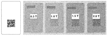
- a plastic molded product may have various colors, and a 3D digital code may be formed regardless of the type of color of the plastic molded product.
- the recognition of the 3D digital code tends to be somewhat poor.
- a recognition rate of about 97% or higher can be secured, which will be described in detail below.
- Another aspect of the present invention relates to a plastic molded article according to another specific embodiment.
- Figure 11 schematically illustrates a cross-section of a plastic molded product (10) according to another specific example of the present invention.
- the above plastic molded product (10) has a 3D digital code (P) formed three-dimensionally on at least one surface, and the 3D digital code includes a concave portion (12) and a protrusion portion (11), and is formed by injection molding of the plastic molded product.
- One of the concave portion (12) or the protrusion portion (11) is characterized by having a diffuse reflection surface (13) or a glossy surface (13). Since it has the diffuse reflection surface or the glossy surface, it can have an excellent recognition rate regardless of the color or pattern shape.
- the above 3D digital code (P) is made of the same material as the plastic molded product and is formed integrally with the plastic molded product.
- the above 3D digital code may be a QR code or a barcode.
- Fig. 2(a) illustrates a QR code as an example of the 3D digital code (P)
- Fig. 2(b) illustrates a barcode as an example of the 3D digital code (P).
- the above 3D digital code is formed simultaneously with the molded product by injection of the plastic molded product. Accordingly, since a separate laser processing or etching process or other subsequent processes are unnecessary, not only can productivity be greatly improved, but also a 3D digital code can be assigned to a curved surface.
- the above 3D digital code can contain information about the material of the plastic molded product, such as information about the components, component ratio, color, and additives.
- the plastic was classified according to the description of HDPE, PP, etc. indicated on the surface of the plastic, and if the description was damaged and could not be found or was not indicated, it had no choice but to be discarded and incinerated.
- plastics such as PET, PP, LDPE, PS, HDPE, PVC, PC, LDPE, PC-ABS, HPPS, acrylic resin, melanin resin, urea resin, epoxy resin, urethane resin, and silicone resin
- 3D digital code recognition 3D digital code recognition
- information about the component ratio, reinforcing material, color, and additives can be known. Therefore, classification by material, component, and additive is easy, and most discarded plastics can be recycled.
- detailed classification is possible, such as whether or not it is fiber reinforced, whether or not it contains 50% or more glass fiber, whether or not it contains a flame retardant, and whether or not a matting agent is added.
- Plastics classified in this way can be recycled according to the appropriate recycling process for each material/component. In this way, energy consumption and labor consumption in the classification and recycling process can be greatly reduced, and the amount of plastic discarded can be greatly reduced, thereby achieving carbon neutrality.
- the above 3D digital code pattern may have an engraved pattern, a relief pattern, or a perforated pattern.
- Fig. 3 (a) shows an engraved pattern, (b) shows a relief pattern, and (c) shows a perforated pattern.
- the entire 3D digital code may have an engraved pattern, a relief pattern, or a perforated pattern.
- the 3D digital code is formed by a combination of two or more types of an engraved pattern, a relief pattern, or a perforated pattern.
- the above 3D digital code has a thickness (t), and the thickness may be about 1.0 mm or more, preferably about 1.5 mm or more, for example, about 1.5 to about 5 mm. Conventionally, the thickness was in the micron unit because it was formed by processing such as laser or etching. In the present invention, since the thickness of the pattern is about 1.0 mm or more, the 3D digital code recognition rate does not decrease and no error occurs even after long-term use.
- FIG. 4 illustrates a pattern of a 3D digital code according to depth according to another specific example of the present invention. As illustrated in FIG. 4, the deeper the depth of the pattern, the clearer the pattern and the higher the recognition rate. When the thickness of the 3D digital code is about 0.5 mm, the code recognition rate can drop to about 80%, and when the thickness is at least about 1.0 mm or more, the code recognition rate can secure about 97% or more.
- Figure 7 schematically illustrates a cross-section of a pattern according to one specific embodiment of the present invention.
- the 3D digital code has a thickness direction pattern in the form of an oblique plane (P1).
- the oblique plane (P1) may form an angle ( ⁇ ) of about 5 to about 45 degrees from the thickness direction.
- the angle ( ⁇ ) is about 10 to about 30 degrees, preferably about 15 to about 25 degrees. In the above range, the pattern is less likely to be broken or damaged, and the pattern recognition rate is excellent.
- the surface (W1) that is in contact with the bottom of the mold is smaller than the surface (W2) located at the top of the mold. In this case, the pattern is less likely to be damaged or broken, and the pattern recognition rate is excellent.
- the above 3D digital code is not printed. Therefore, it does not contain ink.
- the above 3D digital code is not formed through post-processing such as laser or etching, but is formed simultaneously with the injection of the molded product, so it is economical and does not require separate costs or energy consumption.
- the above 3D digital code pattern may be formed on about 30% or more, about 50% or more, about 70% or more, about 80% or more, about 85% or more, about 90% or more, about 95% or more, about 99% or more of the surface of the plastic molded product, or the entire surface.
- Fig. 2 shows a case where a 3D digital code is formed on an entire surface of a plastic molded product. In another specific example, the entire surface of the plastic molded product may be formed with a 3D digital code.
- the 3D digital code is formed by about 30% or more, even if a part of the plastic molded product is broken or a part of a broken piece is broken, the material can be easily recognized and classified using the 3D digital code. Accordingly, while previously broken plastic pieces were difficult to recycle, the plastic molded product of the present invention can be easily recovered.
- the material of the above plastic molded product can be any resin that can be recycled, and examples thereof include, but are not limited to, polyester, polyolefin, polystyrene, polyvinyl chloride, ABS, polycarbonate, silicone resin, etc. These may be used alone or in combination.
- plastic molded products include housings for electronic products, food packages, disposable product packages, etc., and include all products to which recyclable plastics are applied.
- the above-described diffuse reflection surface (13) or glossy surface (13) can be formed by surface treatment.
- the above-described diffuse reflection or glossy surface treatment can be formed by physically or chemically etching the mold to treat the surface of the mold, and then using the surface-treated mold for injection molding, thereby imprinting the diffuse reflection or glossy surface.
- the mold surface-treated By using the mold surface-treated in this way, the diffuse reflection or glossy surface can be obtained only by injection molding without a separate post-treatment process.
- the method for manufacturing the above plastic molded product can be manufactured by injection molding according to the method illustrated in FIG. 8. Specifically, it includes the steps of (a) preparing a mold (20) having a 3D digital code (P) engraved thereon, (b) injecting molten plastic (10a) into the mold (20) to form a plastic molded product (10) in which the 3D digital code (P) is formed three-dimensionally, and (c) separating the plastic molded product (10) from the mold (20).
- the separated plastic molded product (10) has a 3D digital code pattern formed three-dimensionally on at least one surface, and the 3D digital code pattern includes a concave portion and a protrusion portion.
- the concave portion (12) or the protrusion portion (11) has a diffuse reflection or glossy surface, it is possible to have an excellent recognition rate regardless of the color or pattern shape of the plastic molded product.
- the above mold has a mold pattern portion (21) formed as shown in the mold cross-section of Fig. 9a, and further, the cross-section of the mold pattern portion (21) may be tapered.
- Another aspect of the present invention is a method for recycling the above plastic molded product.
- the above method includes a step of recognizing a 3D digital code formed on at least one surface of waste plastic with a terminal and classifying the waste plastic material by type.
- waste plastics may be broken during the collection process, and in the case of broken waste plastic pieces, since it is not possible to know what product material they are, it is difficult to classify them and they cannot be recycled.
- the present invention has a 3D digital code formed on the waste plastic material itself, even broken pieces can be recognized by the terminal, and the recognized parts can be classified and recycled.
- information including the type of material is stored in the 3D digital code.
- Information that can be stored includes, but is not limited to, the type of material such as PET, PP, LDPE, PS, HDPE, PVC, OTHER, the color of the material, the manufacturer, and additives.
- Another aspect of the present invention is a method for recovering waste plastic using a 3D digital code.
- Figure 12 is a conceptual diagram showing a recovery method according to one specific example of the present invention.
- plastics classified in this way can be recycled through an appropriate recycling process. In this way, energy and labor consumption can be significantly reduced during the classification and recycling process, and the amount of plastic discarded can be significantly reduced, thereby achieving carbon neutrality.
- the above method includes a step of recognizing a 3D digital code formed on at least one side of waste plastic (15) by a terminal (30) and classifying the waste plastic material by type.
- the waste plastic includes a 3D digital code on at least one side and can be recognized by the terminal.
- the waste plastic is formed by the method for manufacturing the plastic molded product.
- it may be a speaker, an air purifier, a humidifier, a home appliance housing, a vacuum cleaner, a food packaging material, etc.
- waste plastics may be broken during the collection process, and in the case of broken waste plastic pieces, since it is not possible to know what product material they are, it is difficult to classify them and they cannot be recycled.
- the present invention has a 3D digital code formed on the waste plastic material itself, even broken pieces can be recognized by the terminal, and the recognized parts can be classified and recycled.
- information including the type of material is stored in the 3D digital code.
- Information that can be stored includes, but is not limited to, the type of material such as PET, PP, LDPE, PS, HDPE, PVC, OTHER, the color of the material, the manufacturer, and additives.
- the above-mentioned waste plastic has a 3D digital code pattern formed on at least one surface, and the 3D digital code pattern and the plastic molded product are formed integrally.
- the 3D digital code pattern may be formed on about 30% or more, about 50% or more, about 70% or more, about 80% or more, about 85% or more, about 90% or more, about 95% or more, about 99% or more or the entire surface of the plastic molded product.
- the above 3D digital code is formed simultaneously with the injection molding of the plastic molded product, it is made of the same material as the plastic molded product and is formed integrally with the plastic molded product.
- the 3D digital code may be a QR code or a barcode.
- the above 3D digital code pattern may have an engraved pattern, a relief pattern or a perforated pattern.
- the 3D digital code is formed by a combination of a perforated pattern and a relief/engraved pattern.
- the above 3D digital code has a thickness (t), and the thickness may be about 1.0 mm or more, preferably about 1.5 mm or more, for example, about 1.5 to about 5 mm.
- the digital code can be easily recognized within the above range.
- the digital code was formed by processing such as laser or etching, and the thickness was in the micron unit.
- the 3D digital code recognition rate does not decrease and no error occurs even after long-term use.
- FIG. 13 illustrates closed-loop recycling of waste plastic according to one specific example of the present invention
- FIG. 14 compares a conventional attached/printed 2D digital code method with an injection-molded 3D digital code method of the present invention.
- a waste plastic management company collects the waste plastic, separates the label or sticker, and classifies it by type according to the product material indicated on a portion of the waste plastic.
- the work of separating the label or sticker was inevitably involved, which wasted manpower and energy and could be a major cause of environmental pollution.
- the waste plastic is damaged, there is a problem that the product cannot be recycled and is discarded as is because it is not known what material it is.
- the 3D digital code of the present invention is formed by injection molding rather than being printed, there is no need to remove the sticker or the adhesive.
- the opening itself as an open 3D digital code pattern, it is possible to contain product-related information while providing a design effect in addition to the practical effect of a ventilation hole.
- the 3D digital code can be applied to a large area, even if the product is damaged, it can be easily classified and recycled without being discarded. Accordingly, it can also contribute to a circular economy as shown in Fig. 13.
- the conventional method necessarily involved a sticker and adhesive removal process, but when applying the plastic molded product of the present invention, the sticker or adhesive removal process is unnecessary because product information can be included in the product itself through injection.
- a 'cell' is a unit structure forming a 3D digital code (e.g., a 3D digital code) pattern and having a protruding or concave shape.
- a 3D digital code e.g., a 3D digital code
- a 'dot' is one of the cell shapes and has a square or circular shape when viewed in the frontal direction.
- Another aspect of the present invention relates to a method for forming a 3D digital code pattern with improved injection properties.
- the method includes a step of injection-molding a plastic molded product having a 3D digital code pattern formed three-dimensionally using a mold having a pattern formed to transfer a 3D digital code pattern.
- the mold is characterized in that a pattern portion is provided such that cells forming the 3D digital code pattern include connecting cells having a dot-connection structure, the 3D digital code pattern stores information including a type of material for classification and recycling of the plastic molded product, and the connecting cells satisfy the following Equation 1.
- d is the width of a cell forming a 3D digital code pattern of a plastic molded product
- t is the height of a cell forming a 3D digital code pattern
- FIG. 15 schematically illustrates (a) a cross-section of a pattern before improvement and (b) a cross-section of a pattern after improvement, (c) is a front view of the pattern (a), and (d) is a front view of the pattern (b).
- the cross-section (P1) of the pattern before improvement (a) has d/t of 1 or less.
- the pattern (P2) improved by the present invention has a dot-connected structure in which cells are connected to each other, and may have a value in the range of 1.5 to 10, preferably 2 to 9, and more preferably 2.5 to 7 according to Equation 1. In the above range, there is no pattern damage, and the pattern recognition rate is excellent.
- the pattern having such a dot connection structure is about 50% or more, preferably about 75% or more, and more preferably about 80% or more of the entire 3D digital code pattern.
- (c) and (d) of Fig. 15 are shapes of the pattern as viewed from the front, and a is the length of the cell. In one specific example, d/a may be 1.5 to 10.
- the mold for forming the above pattern is a mold in which a pattern is formed to transfer a 3D digital code pattern, the mold includes a receiving portion for receiving molten plastic; and a pattern portion for transferring the 3D digital code pattern to the molten plastic, and the pattern portion is provided such that cells forming the 3D digital code pattern include connecting cells having a dot-connected structure.
- Fig. 16(a) shows a pattern of a 3D digital code before improvement transferred to a plastic molded product according to one specific example
- Fig. 16(b) shows a pattern of a 3D digital code after improvement
- Fig. 17(a) shows a pattern of a 3D digital code of a mold before improvement according to another specific example
- Fig. 17(b) shows a pattern of a 3D digital code of a mold after improvement.
- the patterns of the 3D digital code before improvement of FIG. 16 (a) and FIG. 18 (a) are formed in such a way that each fine cell is formed independently.
- the cells forming the 3D digital code pattern include connecting cells having a dot-connection structure, thereby preventing damage to the pattern.
- the patterns of the 3D digital code after improvement of FIG. 16 (b) and FIG. 18 (b) are characterized in that the cells forming the 3D digital code pattern form connecting cells having a dot-connection structure.
- the connecting cells are set to be about 50% or more of the total cells, preferably about 75% or more, and more preferably about 80% or more. In the above range, damage to the cell shape during production is prevented, and the phenomenon of dust accumulating between cells even after long-term use can be minimized.
- Fig. 19 (a) shows a pattern of a 3D digital code of a mold before improvement according to another specific example
- Fig. 19 (b) shows a pattern of a 3D digital code of a mold after improvement.
- Figure 20 (a) is a pattern of a 3D digital code transferred before improvement
- Figure 20 (b) is a pattern of a 3D digital code transferred after improvement.
- the shape of the mold can be modified to further improve the injection properties.
Landscapes
- Engineering & Computer Science (AREA)
- Mechanical Engineering (AREA)
- Manufacturing & Machinery (AREA)
- Physics & Mathematics (AREA)
- General Physics & Mathematics (AREA)
- Theoretical Computer Science (AREA)
- Environmental & Geological Engineering (AREA)
- Injection Moulding Of Plastics Or The Like (AREA)
- Moulds For Moulding Plastics Or The Like (AREA)
Abstract
본 발명의 플라스틱 성형품은 적어도 일면에 3D 디지털 코드 패턴이 입체적으로 형성된 플라스틱 성형품이며, 상기 3D 디지털 코드는 상기 플라스틱 성형품의 사출에 의해 형성된 것인 플라스틱 성형품을 제공한다.
Description
본 발명은 플라스틱 성형품 및 그 제조방법에 관한 것이다. 보다 구체적으로, 본 발명은 라벨이나 후가공으로 구현되는 종래의 2D 디지털 코드(QR 및 Bar)를 배제하고 플라스틱 부품의 일부가 되게끔 입체적으로 재탄생시켜 친환경적인 플라스틱 성형품 및 그 제조방법에 관한 것이다. 또한, 색상이나 패턴 형태에 무관하게 인식률이 우수한 플라스틱 성형품 및 그 제조방법을 제공한다.
대부분의 패키지나 소비재에는 도 1(a)~(d)와 같이, 2D 3D 디지털 코드(Quick Response Code)나 Bar 코드가 스티커/라벨로 부착되거나 인쇄/에칭 등의 후가공으로 적용되어 제품의 정보를 전달해 주는 역할을 하고 있다. 그러나, 환경적 측면에서 보면 이는 오염물질로 간주되어 그 부품의 재활용성을 낮추는 요인이 된다. 뿐만 아니라, 라벨이나 에칭은 시간이 지남에 따라 떼어지거나 지워질 수도 있다.
이처럼, 플라스틱 소비재에 부착/인쇄된 2D 디지털 코드는 환경적인 측면에서 보면 오염물질로 간주되어 그 부품의 재활용성을 낮추는 요인이 되고, 시간이 지남에 따라 떼어지거나 지워질 수도 있기 때문에, 인쇄, 부착 등의 필요 없이 플라스틱 부품의 일부로서 디지털 코드를 형성시키는 것이 필요하다.
상기 문제를 해결하기 위해, 레이저 가공을 통해 각인하는 기술이 검토되고 있으나, 별도의 후가공이 필요하고 시간 및 에너지 낭비로 인해 실용성이 없다.
한편, 사용된 폐플라스틱은 수거 후 재활용되며, 통상 PET, PP, LDPE, PS, HDPE, PVC, OTHER 등 소재 별로 분류되어 재활용된다. 그런데, 폐플라스틱이 파손되거나 어떤 소재인지 알 수 없는 경우, 분류가 어렵기 때문에 재활용될 수 없으며, 이로 인해 환경오염의 문제가 발생하고, 소재별 분류작업으로 인한 비용이 증가하는 문제가 있다.
따라서, 라벨 부착이나 후가공이 필요 없고, 파손되어도 용이하게 재활용될 수 있는 플라스틱 제품 및 그 제조방법의 개발이 필요하다.
또한, 본 발명자는 플라스틱의 사출성형 시, 몰드에 3D 디지털 코드 패턴을 각인시켜 사출과 동시에 플라스틱 성형품에 3D 디지털 코드 패턴을 형성시키는 방법을 개발한 바 있다. 그러나, 패턴이 양각을 갖거나, 혹은 성형품의 색상이 어두울 경우, 인식률이 저하되는 문제가 있다.
따라서, 색상이나 패턴 형태에 무관하게 인식률이 우수한 3D 디지털 코드를 갖는 플라스틱 성형품 및 그 제조방법의 개발이 필요하다.
관련 선행기술은 대한민국 등록특허 1597471호이다.
본 발명의 목적은 라벨 부착이나 후가공이 필요 없는 플라스틱 성형품 및 그 제조방법을 제공하기 위한 것이다.
본 발명의 다른 목적은 색상이나 패턴 형태에 무관하게 인식률이 우수한 플라스틱 성형품 및 그 제조방법을 제공하기 위한 것이다.
본 발명의 또 다른 목적은 소리, 공기, 액체, 기체가 유출/입되는 통로인 개구부가 형성되는 플라스틱 성형품에 있어서, 개구부에 3D 디지털 코드를 포함시켜 재활용성과 심미감을 모두 달성할 수 있는 플라스틱 성형품 및 그 제조방법을 제공하기 위한 것이다.
본 발명의 또 다른 목적은 제품의 일부가 파손되어도 디지털 코드에 의해 재활용 정보를 읽을 수 있어 용이하게 분류 및 재활용될 수 있는 플라스틱 성형품 및 그 제조방법을 제공하기 위한 것이다.
본 발명의 또 다른 목적은 한번의 사출성형으로 부착이나 천공 등의 후속공정 없이 용이하게 제조할 수 있는 플라스틱 성형품 및 그 제조방법을 제공하기 위한 것이다.
본 발명의 또 다른 목적은 3D 디지털 코드를 곡면에도 적용 가능한 플라스틱 성형품 및 그 제조방법을 제공하기 위한 것이다.
본 발명의 또 다른 목적은 3D 디지털 코드를 대면적에도 적용 가능하여, 디자인효과까지 주면서 제품 관련정보를 담을 수 있는 플라스틱 성형품 및 그 제조방법을 제공하기 위한 것이다.
본 발명의 또 다른 목적은 Closed-loop Recycling과 순환 경제에 기여할 수 있는 플라스틱 성형품 및 그 제조방법을 제공하기 위한 것이다.
본 발명의 또 다른 목적은 라벨 부착이나 후가공이 필요 없는 플라스틱 성형품의 성형에 있어서, 사출성형시 불량률을 감소시킬 수 있는 사출성이 개선된 3D 디지털 코드 형성방법, 이를 위한 금형 및 이로부터 형성된 플라스틱 성형품을 제공하기 위한 것이다.
본 발명의 또 다른 목적은 라벨이나 후가공으로 구현되는 종래의 2D 디지털 코드(QR 및 Bar)를 단일 사출로 플라스틱 부품의 일부가 되게끔 입체적으로 재탄생시켜 탄소저감에 기여하고, 미세한 3D 디지털 코드의 사출성을 개선하는 동시에, 인식율을 향상시키는 3D 디지털 코드 형성방법, 이를 위한 금형 및 이로부터 형성된 플라스틱 성형품을 제공하기 위한 것이다.
본 발명의 또 다른 목적은 3D 디지털 코드 디자인을 변형하는 방법으로 금형 훼손을 개선하고 사출성이 향상된 3D 디지털 코드 형성방법, 이를 위한 금형 및 이로부터 형성된 플라스틱 성형품을 제공하기 위한 것이다.
본 발명의 상기 및 기타의 목적들은 하기 설명되는 본 발명에 의하여 모두 달성될 수 있다.
1. 본 발명의 하나의 관점은 플라스틱 성형품에 관한 것이다. 상기 플라스틱 성형품은 적어도 일면에 3D 디지털 코드 패턴이 입체적으로 형성된 플라스틱 성형품이며, 상기 3D 디지털 코드는 상기 플라스틱 성형품의 분류 및 재활용을 위한 소재의 종류를 포함하는 정보가 저장된 것이며, 상기 플라스틱 성형품의 사출에 의해 형성되고, 상기 3D 디지털 코드는 상기 플라스틱 성형품과 동일한 재질이며, 플라스틱 성형품과 일체로 형성된 것이다.
2. 상기 1 구체예에서, 상기 3D 디지털 코드는 QR코드 또는 바코드일 수 있다.
3. 상기 1 또는 2 구체예에서, 상기 3D 디지털 코드 패턴은 음각패턴, 양각패턴 또는 천공패턴을 가질 수 있다.
4. 상기 1 내지 3 구체예에서, 상기 3D 디지털 코드는 두께를 가지며, 상기 두께는 약 1.0 mm 이상일 수 있다.
5. 상기 1 내지 4 구체예에서, 상기 3D 디지털 코드는 인쇄된 것이 아닐 수 있다.
6. 상기 1 내지 5 구체예에서, 상기 3D 디지털 코드 패턴은 플라스틱 성형품 표면의 약 30% 이상, 약 50% 이상, 약 70% 이상, 약 80% 이상, 약 85% 이상, 약 90% 이상, 약 95% 이상, 약 99% 이상 또는 전면으로 형성된 것일 수 있다.
7. 상기 1 내지 6 구체예에서, 상기 3D 디지털 코드 패턴은 이중 사출에 의해 형성된 것일 수 있다.
8. 상기 1 내지 7 구체예에서, 상기 플라스틱 성형품은 적어도 일측에 개구부가 형성된 플라스틱 성형품이며, 상기 개구부는 기체, 액체 또는 소리를 포함하는 유체가 통과될 수 있고, 상기 개구부는 상기 3D 디지털 코드를 포함하며, 단말기에 의해 인식될 수 있다.
9. 상기 1 내지 8 구체예에서, 상기 개구부는 스피커 그릴, 벤트 홀, 공기청정기 배출구, 가습기 배출구, 가전제품 벤트홀, 진공청소기 배출구 또는 식품포장용기 배출구를 포함할 수 있다.
10. 상기 1 내지 9 구체예에서, 상기 3D 디지털 코드는 곡면 상에 형성될 수 있다.
11. 본 발명의 다른 관점은 플라스틱 성형품의 제조방법이다. 상기 제조방법은 3D 디지털 코드가 각인된 몰드를 사용하여 용융 플라스틱을 사출성형하는 단계; 및 상기 사출된 플라스틱 성형품과 몰드를 분리하는 단계;를 포함하며, 상기 3D 디지털 코드는 상기 플라스틱 성형품의 분류 및 재활용을 위한 소재의 종류를 포함하는 정보가 저장된 것 것이다.
12. 상기 11 구체예에서, 상기 플라스틱 성형품은 적어도 일면에 3D 디지털 코드 패턴이 입체적으로 형성된 것일 수 있다.
13. 상기 11 또는 12 구체예에서, 상기 플라스틱 성형품은 적어도 일측에 개구부가 형성되고, 상기 개구부는 기체, 액체 또는 소리를 포함하는 유체가 통과될 수 있고, 상기 개구부는 3D 디지털 코드를 포함하며, 단말기에 의해 인식될 수 있다.
14. 상기 11 내지 13 구체예에서, 상기 플라스틱 성형품은 적어도 일면에 3D 디지털 코드 패턴이 개방형으로 형성되고, 그리고 상기 개방형 3D 디지털 코드 패턴과 플라스틱 성형품이 일체로 형성된 것일 수 있다.
15. 본 발명의 또 다른 관점은 다른 구체예에 의한 플라스틱 성형품에 관한 것이다. 상기 플라스틱 성형품은 적어도 일면에 3D 디지털 코드 패턴이 입체적으로 형성된 것이며, 상기 3D 디지털 코드는 오목부와 돌출부를 포함하고, 상기 플라스틱 성형품의 사출에 의해 형성된 것이고, 상기 오목부 또는 돌출부 중 어느 하나는 난반사 표면 또는 광택 표면을 갖는 것을 특징으로 한다.
16. 상기 15 구체예에서, 상기 3D 디지털 코드는 상기 플라스틱 성형품과 동일한 재질이며, 플라스틱 성형품과 일체로 형성된 것이다.
17. 상기 15 또는 16 구체예에서, 상기 3D 디지털 코드는 상기 플라스틱 성형품과 동일한 재질이며, 플라스틱 성형품과 일체로 형성된 것이다.
18. 본 발명은 다른 관점은 폐플라스틱의 회수 방법이다. 상기 회수 방법은 3D 디지털 코드를 활용한 폐플라스틱의 회수 방법이며, 상기 방법은 폐플라스틱의 적어도 일면에 형성된 3D 디지털 코드를 단말기로 인식시켜 폐플라스틱 소재의 종류별로 분류하는 단계를 포함하고, 상기 3D 디지털 코드에는 소재의 종류를 포함하는 정보가 저장된 것이고, 상기 폐플라스틱은 적어도 일면에 3D 디지털 코드 패턴이 입체적으로 형성되고, 그리고 상기 개방형 3D 디지털 코드 패턴과 플라스틱 성형품이 일체로 형성된 것이다.
19. 상기 18 구체예에서, 상기 3D 디지털 코드는 상기 플라스틱 성형품과 동일한 재질이며, 상기 플라스틱 성형품의 사출에 의해 형성된 것일 수 있다.
20. 상기 18 또는 19 구체예에서, 상기 플라스틱 성형품은 적어도 일측에 개구부가 형성된 플라스틱 성형품이며, 상기 개구부는 기체, 액체 또는 소리를 포함하는 유체가 통과될 수 있고, 상기 개구부는 상기 3D 디지털 코드를 포함하며, 단말기에 의해 인식될 수 있는 것이다.
21. 본 발명의 또 다른 관점은 3D 디지털 코드 패턴 형성방법이다. 상기 3D 디지털 코드 패턴 형성방법은 사출성이 개선된 3D 디지털 코드 패턴 형성방법이며, 상기 방법은 3D 디지털 코드 패턴을 전사하도록 패턴이 형성된 금형을 사용하여 3D 디지털 코드 패턴이 입체적으로 형성된 플라스틱 성형품을 사출성형하는 단계를 포함하고, 상기 금형은, 상기 3D 디지털 코드 패턴을 이루는 셀이 도트-연결 구조를 갖는 연결셀을 포함하도록 패턴부가 마련되고, 상기 3D 디지털 코드 패턴은 상기 플라스틱 성형품의 분류 및 재활용을 위한 소재의 종류를 포함하는 정보가 저장된 것이고, 상기 연결셀은 하기 식 1을 만족한다:
[식 1]
d/t = 1.5~10
상기 식 1에서, d는 플라스틱 성형품의 3D 디지털 코드 패턴을 이루는 셀의 너비이고, t는 3D 디지털 코드 패턴을 이루는 셀의 높이이다.
22. 상기 21 구체예에서, 상기 3D 디지털 코드는 상기 플라스틱 성형품과 동일한 재질이며, 플라스틱 성형품과 일체로 형성된 것일 수 있다.
23. 상기 21 또는 22 구체예에서, 상기 t는 1.0 mm 이상일 수 있다.
24. 본 발명의 또 다른 관점은 또 다른 구체예에 의한 플라스틱 성형품에 관한 것이다. 상기 플라스틱 성형품은 상기 21 내지 23 구체예의 3D 디지털 코드 패턴 형성방법에 의해 형성된 3D 디지털 코드 패턴을 갖는 것을 특징으로 한다.
본 발명은 3D 디지털 코드를 플라스틱 부품의 일부로써 입체적으로 구현하고 3D 디지털 코드의 깊이(음각/양각), 플라스틱의 명도 및 색상, 코드의 사이즈 및 디자인 변형이 우수하여 디자인 자유도가 탁월하고, 제품의 일부가 파손되어도 디지털 코드에 의해 재활용 정보를 읽을 수 있어 용이하게 분류 및 재활용될 수 있으며, 한번의 사출성형으로 라벨 부착이나 천공 등의 후속공정의 필요 없이 용이하게 제조할 수 있고, 3D 디지털 코드를 곡면에도 적용가능 하며, 3D 디지털 코드를 대면적에도 적용 가능하여, 디자인효과까지 주면서 제품 관련정보를 담을 수 있으며, 순도 높은 폐플라스틱의 재활용이 가능하여 Closed-loop Recycling과 순환 경제에 기여할 수 있으며, 또한, 색상이나 패턴 형태에 무관하게 인식률이 우수한 디지털 코드를 가질 수 있고, 필요에 따라, 소리, 유체가 관통되는 개구부에 대해 디지털 코드를 부여하여, 재활용성과 심미감을 모두 달성할 수 있어 친환경적일 수 있으며, 필요에 따라, 미세한 3D 코드의 사출성을 개선하는 동시에 인식율을 향상시킬 수 있는 플라스틱 성형품 및 그 제조방법을 얻는 발명의 효과를 갖는다.
도 1(a)~(d)는 종래의 디지털 코드가 형성된 플라스틱 성형품이다.
도 2(a)~(b)는 본 발명의 하나의 구체예에 따른 플라스틱 성형품이고, 도 2(c)는 개구부가 형성된 다른 구체예에 따른 플라스틱 성형품이다.
도 3은 본 발명의 구체예에 따른 3D 디지털 코드의 패턴을 개략적으로 나타낸 것이다.
도 4는 본 발명의 다른 구체예에 따라 깊이에 따른 3D 디지털 코드의 패턴을 나타낸 것이다.
도 5는 본 발명의 다른 구체예에 따른 3D 디지털 코드의 패턴을 개략적으로 나타낸 것이다.
도 6의 (a)는 본 발명의 다른 구체예에 따른 3D 디지털 코드가 천공패턴과 양각/음각 패턴의 조합으로 형성된 성형품의 측면 사시도를 나타낸 것이고, (b)는 (a)의 C-C' 면의 횡단면을 개략적으로 도시한 것이다.
도 7은 본 발명의 하나의 구체예에 따른 패턴의 단면을 개략적으로 도시한 것이다.
도 8은 본 발명의 하나의 구체예에 따른 플라스틱 성형품의 제조방법을 개략적으로 도시한 것이다.
도 9a는 본 발명의 하나의 구체예에 따른 몰드의 단면을 개략적으로 도시한 것이다.
도 9b는 본 발명의 다른 구체예에 따른 몰드의 패턴부이다.
도 10은 본 발명의 다른 구체예에 따라 색상에 따른 3D 디지털 코드의 패턴을 나타낸 것이다.
도 11은 본 발명의 다른 구체예에 따른 플라스틱 성형품의 단면을 개략적으로 도시한 것이다.
도 12는 본 발명의 하나의 구체예에 따른 회수방법을 나타낸 개념도이다.
도 13은 본 발명의 하나의 구체예에 따른 폐플라스틱의 Closed-loop Recycling을 나타낸 것이다.
도 14는 종래의 부착/인쇄된 2D 디지털 코드 방식과 본 발명의 사출에 의한 3D 디지털 코드 방식을 비교한 것이다.
도 15는 (a) 개량전 패턴의 단면과 (b) 개량후 패턴의 단면을 개략적으로 도시한 것이다.
도 16의 (a)는 한 구체예에 따른 플라스틱 성형품에 전사된 개량전 3D 디지털 코드의 패턴이고, (b)는 개량후 3D 디지털 코드의 패턴을 나타낸 것이다.
도 17의 (a)는 한 구체예에 따른 개량전 금형의 3D 디지털 코드의 패턴이고, (b)는 개량후 금형의 3D 디지털 코드의 패턴을 나타낸 것이다.
도 18의 (a)는 다른 구체예에 따른 플라스틱 성형품에 전사된 개량전 3D 디지털 코드의 패턴이고, (b)는 개량후 3D 디지털 코드의 패턴을 나타낸 것이다.
도 19의 (a)는 다른 구체예에 따른 개량전 금형의 3D 디지털 코드의 패턴이고, (b)는 개량후 금형의 3D 디지털 코드의 패턴을 나타낸 것이다.
도 20의 (a)는 개량전 전사된 3D 디지털 코드의 패턴이고, (b)는 개량후 전사된 3D 디지털 코드의 패턴이다.
하나의 관점은 플라스틱 성형품에 관한 것이다.
도 2(a) 및 도 2(b)는 본 발명의 하나의 구체예에 따른 플라스틱 성형품(10)이고, 도 2(c)는 개구부가 형성된 다른 구체예에 따른 플라스틱 성형품에 관한 것이다.
상기 플라스틱 성형품(10)은 적어도 일면에 3D 디지털 코드(P)가 입체적으로 형성된 것이다.
도 2(c)에서, 상기 플라스틱 성형품(10)은 적어도 일면에 개구부(P)가 형성된 것이다. 상기 개구부(P)는 기체, 액체 또는 소리를 포함하는 유체가 통과될 수 있고, 상기 개구부는 3D 디지털 코드를 포함하며, 단말기에 의해 인식될 수 있다. 구체적으로, 3D 디지털 코드 패턴이 개방형으로 형성되고, 그리고 상기 개방형 3D 디지털 코드 패턴과 플라스틱 성형품이 일체로 형성된 것이다.
도 2(c)에서, 상기 개구부는 상기 플라스틱 성형품을 사출할 때 형성된다. 이에 따라, 별도의 레이저 가공이나, 에칭공정 등 후속공정이 불필요하기 때문에, 생산성을 크게 개선할 수 있을 뿐만 아니라, 곡면에도 3D 디지털 코드의 부여가 가능하다.
상기 3D 디지털 코드는 상기 플라스틱 성형품과 동일한 재질이며, 플라스틱 성형품과 일체로 형성된 것이다. 따라서, 3D 디지털 코드 라벨링을 위한 부착이나 탈착이 불필요하며, 플라스틱 성형품과 동일한 재질이므로 한번에 재활용 분류가 가능하다.
상기 3D 디지털 코드는 QR코드 또는 바코드일 수 있다. 도 2(a)에는 3D 디지털 코드(P)의 예시로 QR코드를 나타낸 것이고, 도 2(b) 에는 3D 디지털 코드(P)의 예시로 바코드를 나타낸 것이다. 상기 3D 디지털 코드는 상기 플라스틱 성형품의 사출에 의해 성형품과 동시에 형성된 것이다. 이에 따라, 별도의 레이저 가공이나, 에칭공정 등 후속공정이 불필요하기 때문에, 생산성을 크게 개선할 수 있을 뿐만 아니라, 곡면에도 3D 디지털 코드의 부여가 가능하다.
상기 3D 디지털 코드에는 플라스틱 성형품의 소재에 관한 정보, 예컨대 성분, 성분비, 색상, 첨가제 등의 정보를 담을 수 있다. 종래에는 플라스틱 표면에 표시된 HDPE, PP 등의 기재에 따라 분류하였고, 파손되어 표시를 찾을 수 없거나 표기가 되어 있지 않은 경우에는 그대로 폐기하여 소각할 수 밖에 없었다. 그러나, 본 발명에서는 3D 디지털 코드 인식에 의해 PET, PP, LDPE, PS, HDPE, PVC, PC, LDPE, PC-ABS, HPPS, 아크릴 수지, 멜라닌 수지, 요소수지, 에폭시 수지, 우레탄 수지, 실리콘 수지 등 모든 종류의 플라스틱을 정확하게 분류할 수 있을 뿐만 아니라, 성분비, 보강재, 색상, 첨가제 등의 정보를 알 수 있다. 따라서, 소재별, 성분별, 첨가제별로 분류가 용이하고, 폐기된 플라스틱 대부분을 재활용할 수 있는 것이다. 예를 들면, 동일한 폴리카보네이트 소재라도 섬유강화 여부, 유리섬유 50% 이상 여부, 난연제 포함여부, 소광제 첨가여부 등 세부적인 분류가 가능하다. 이렇게 분류된 플라스틱은 소재/ 성분별로 적합한 재생공정에 따라 재생할 수 있다. 이와 같이, 분류 및 재생 과정에서 에너지 소비와 노동력 소비를 대폭 감소시킬 수 있고, 폐기시키는 플라스틱을 대폭 줄일 수 있어 탄소중립을 이룰 수 있는 것이다.
상기 3D 디지털 코드 패턴은 음각패턴, 양각패턴 또는 천공패턴을 가질 수 있다. 도 3의 (a)는 음각패턴을 나타낸 것이고, (b)는 양각패턴을 나타낸 것이며, (c)는 천공패턴을 나타낸 것이다. 본 발명의 하나의 구체예에서는 3D 디지털 코드 전체가 음각패턴, 양각패턴 또는 천공패턴을 가질 수 있다. 본 발명의 다른 구체예에서는 3D 디지털 코드가 음각패턴, 양각패턴 또는 천공패턴의 2종 이상의 조합으로 형성되어 있다.
도 2(c)에서, 상기 개구부는 천공패턴을 가질 수 있다. 본 발명의 다른 구체예에서는 3D 디지털 코드 전체가 개구부로 형성되어 있으며, 전체가 천공패턴을 갖는다. 본 발명의 또 다른 구체예에서는 3D 디지털 코드가 천공패턴과 양각/음각 패턴의 조합으로 형성되어 있다.
이 경우, 천공패턴은 유체 또는 소리가 관통될 수 있으며, 양각/음각 패턴은 유체 및 소리가 관통되지 않고 단지 미감을 부여하는 역할을 한다.
도 3의 (a) 내지 (c)에 도시된 바와 같이, 상기 3D 디지털 코드는 두께(t)를 가지며, 상기 두께는 약 1.0 mm 이상, 바람직하게는 약 1.5 mm 이상, 예를 들면 약 1.5 내지 약 5 mm일 수 있다. 상기 범위 내에서 제조가 용이하고, 디지털 코드를 용이하게 인식할 수 있다. 종래에는 레이저나 에칭 등의 가공에 의해 형성되어 두께가 마이크론 단위였다. 본 발명에서는 패턴의 두께가 약 1.0 mm 이상이므로, 장기간 사용 후에도 3D 디지털 코드 인식률이 저하되지 않고 오류가 발생하지 않는다.
도 4는 본 발명의 다른 구체예에 따라 깊이에 따른 3D 디지털 코드의 패턴을 나타낸 것이다. 도 4에 도시된 바와 같이 패턴의 깊이가 깊을수록 패턴이 선명해지며, 인식률이 높아진다. 3D 디지털 코드의 두께가 약 0.5 mm인 경우, 코드 인식률이 약 80%로 떨어질 수 있으며, 적어도 약 1.0 mm 이상의 두께를 가질 경우, 코드 인식률이 약 97% 이상을 확보할 수 있다.
도 5는 본 발명의 다른 구체예에 따른 3D 디지털 코드의 패턴을 개략적으로 나타낸 것이다.
도 5의 (a) 및 (b)에 도시된 바와 같이, 상기 플라스틱 성형품(10)은 매트한 표면을 가질 수 있다. 또한, 도 5의 (c)에 도시된 바와 같이 플라스틱 성형품(10)은 빗살무늬 패턴을 가질 수 있으며, 상기 빗살무늬 패턴 상에도 3D 디지털 코드를 형성할 수 있다. 또한, 도 5의 (d)에 도시된 바와 같이, 3D 디지털 코드로서, 복수개의 3D 디지털 코드를 연속적으로 형성시켜 특이한 문양을 나타낼 수 있다. 도시되지 않았지만, 상기 플라스틱 성형품 자체는 스트라이프, 도트, 나무결 등의 입체적 무늬 패턴을 가질 수 있다. 입체적 무늬 패턴을 가질 경우, 상기 3D 디지털 코드(P)는 입체적 무늬 패턴 상에 형성될 수 있다. 이와 같이, 플라스틱 성형품(10)이 매트한 표면이 아닌 입체적 무늬 패턴을 가질 경우에도 입체적 무늬 패턴과 3D 디지털 코드는 단일 사출성형 금형에서 동시에 형성될 수 있다.
상기 3D 디지털 코드(P)는 상기 플라스틱 성형품과 동일한 재질이며, 플라스틱 성형품과 일체로 형성된 것이다. 따라서, 3D 디지털 코드 라벨링을 위한 부착이나 탈착이 불필요하며, 플라스틱 성형품과 동일한 재질이므로 한번에 재활용 분류가 가능하다.
도 6의 (a)는 본 발명의 다른 구체예에 따른 3D 디지털 코드가 천공패턴과 양각/음각 패턴의 조합으로 형성된 성형품의 측면 사시도를 나타낸 것이고, 도 6의 (b)는 도 6의 (a)의 C-C' 면의 횡단면을 개략적으로 도시한 것이다. 도시된 바와 같이, 3D 디지털 코드는 천공패턴이 형성된 P1과 음각패턴이 형성된 P2 의 조합으로 형성될 수 있다. 천공패턴이 형성된 P1 부분은 t1 두께를 가지며, 음각패턴이 형성된 P2 부분은 t2 두께를 갖는다. t1 및 t2는 약 1.0 mm 이상, 바람직하게는 약 1.5 mm 이상, 예를 들면 약 1.5 내지 약 5 mm이며, t1 > t2이다. 도면에는 P2가 음각패턴으로 형성되어 있지만, 양각패턴으로 형성되어 있어도 무방하다. 또한, 3D 디지털 코드는 3D 디지털 코드 또는 바코드 형태일 수 있다. 천공패턴은 개구부로서 기체, 액체 또는 소리를 포함하는 유체가 통과될 수 있다.
구체예에서, 상기 개구부는 스피커 그릴, 벤트 홀, 공기청정기 배출구, 가습기 배출구, 가전제품 벤트홀, 진공청소기 배출구 또는 식품포장용기 배출구 등으로 적용될 수 있다.
또한, 본 발명의 3D 디지털 코드는 플라스틱 성형품의 사출성형 시와 동시에 형성되기 때문에 곡면 상에도 형성될 수 있으며, 자체로도 새로운 미감을 부여할 수 있는 것이다.
도 7은 본 발명의 하나의 구체에에 따른 패턴의 단면을 개략적으로 도시한 것이다.
도시된 바와 같이, 상기 3D 디지털 코드는 두께방향 패턴이 사선면(P1)으로 되어 있다. 예를 들면, 상기 사선면(P1)은 두께방향으로부터 약 5 내지 약 45도의 각(θ)을 이룰 수 있다. 구체예에서 상기 각(θ)은 약 10 내지 약 30도, 바람직하게는 약 15 내지 약 25도를 갖는다. 상기 범위에서, 패턴의 파손 또는 훼손이 적고, 패턴 인식률이 우수하다.
또한, 몰드바닥에 접했던 면(W1)은 몰드 상부에 위치하는 면(W2) 보다 작다. 이 경우, 패턴의 파손 또는 훼손이 적고, 패턴 인식률이 우수하다.
상기 3D 디지털 코드는 인쇄된 것이 아니다. 따라서, 잉크를 함유하지 않는다. 또한 상기 3D 디지털 코드는 레이저나 식각 등에 의해 후가공으로 형성된 것이 아니고, 성형품의 사출과 동시에 형성되기 때문에 경제적이고 별도의 비용이나 에너지 소모가 필요하지 않는다.
이러한 3D 디지털 코드 패턴은 플라스틱 성형품 표면의 약 30% 이상, 약 50% 이상, 약 70% 이상, 약 80% 이상, 약 85% 이상, 약 90% 이상, 약 95% 이상, 약 99% 이상 또는 전면으로 형성될 수 있다. 3D 디지털 코드 패턴이 플라스틱 성형품 표면의 약 50% 이상, 바람직하게는 약 70% 이상 형성될 경우, 제품의 일부가 파손되어도 디지털 코드에 의해 재활용 정보를 읽을 수 있어 용이하게 분류 및 재활용될 수 있다.
예컨대, 도 2는 플라스틱 성형품으로서, 스피커를 나타낸 것이며, 플라스틱 성형품의 한 면 전체가 3D 디지털 코드(개방형 3D 디지털 코드)가 형성된 것이다. 도 2에 나타난 바와 같이, 스피커 그릴 자체를 3D 디지털 코드로 형성한 경우, 개구부는 소리가 통과하면서 성형품에 대한 정보를 전달하여 용이하게 재활용될 수 있도록 한다.
다른 구체예에서는 플라스틱 성형품의 전면이 3D 디지털 코드가 형성된 것일 수 있다. 예를 들면, 식품 포장용기의 전면을 개방형 바코드로 형성하여, 공기 통풍을 원활하게 하여 내용물을 신선하게 보관 및 유통할 수 있으며, 새로운 디자인으로 창출할 수 있다.
이와 같이, 3D 디지털 코드가 약 30% 이상 형성되기 때문에, 플라스틱 성형품의 일부가 파손되거나 파손된 조각 일부라도 3D 디지털 코드로 어떤 소재인지 쉽게 인식되고 분류될 수 있다. 따라서, 기존에는 파손된 플라스틱 조각은 재활용이 어려워 폐기할 수 밖에 없었지만, 본 발명의 플라스틱 성형품의 경우 용이하게 회수될 수 있으며, 환경오염의 문제를 대폭 감소시킬 수 있다.
상기 플라스틱 성형품의 재질은 재활용이 가능한 모든 수지가 가능하며, 예를 들면, 폴리에스테르, 폴리올레핀, 폴리스티렌, 폴리염화비닐, ABS, 폴리카보네이트, 실리콘 수지 등이 있으며, 이에 제한되는 것은 아니다. 이들의 단독 또는 블렌드된 재질도 가능하다.
또한, 상기 플라스틱 성형품은 전자제품의 하우징, 식품 패키지, 일회용품 패키지, 등이 있으며, 재활용이 가능한 플라스틱이 적용되는 모든 제품을 포함한다. 이처럼, 전자제품(그릴이나 vent hole이 있는 공기청정기, 스피커 혹은 TV 부품) Housing 표면에 타공형 QR/Bar 코드를 반복적으로 패턴화할 수 있다는 점을 연결시켜, vent hole이나 그릴의 기존 존재 목적인 공기/소리/열 방출 외에 자원순환이라는 새로운 기능을 패턴에 부여할 수 있다. 또한, QR코드가 반복적으로 적용되면 부품이 분리되고 분류되는 과정에서 일부 파손되더라도 인식이 가능하다는 장점을 갖게 된다.
본 발명의 다른 관점은 플라스틱 성형품의 제조방법이다. 상기 제조방법은 3D 디지털 코드가 각인된 몰드를 사용하여 용융 플라스틱을 사출성형하는 단계; 및 상기 사출된 플라스틱 성형품과 몰드를 분리하는 단계;를 포함한다.
도 8은 본 발명의 하나의 구체예에 따른 플라스틱 성형품의 제조방법을 개략적으로 도시한 것이다.
구체적으로, (a) 3D 디지털 코드(P)를 위한 몰드 패턴부(21)가 새겨진 몰드(20)를 마련하고, (b) 상기 몰드(20)에 용융 플라스틱(10a)을 주입하여 3D 디지털 코드(P)가 입체적으로 형성된 플라스틱 성형품(10)을 형성하고, (c) 상기 플라스틱 성형품(10)을 몰드(20)으로부터 분리하는 단계를 포함한다. 이와 같이 분리된 플라스틱 성형품(10)은 적어도 일면에 3D 디지털 코드 패턴이 입체적 및/또는 개방형으로 형성되고, 상기 3D 디지털 코드 패턴과 플라스틱 성형품이 일체로 형성된다.
도 9a은 본 발명의 하나의 구체예에 따른 몰드(금형(20))의 단면을 개략적으로 도시한 것이다.
도시된 바와 같이, 몰드(20)에는 3D 디지털 코드(P)를 위한 몰드 패턴부(21)가 형성되어 있다. 상기 몰드 패턴부(21)의 두께(t)는 약 1.0 mm 이상, 바람직하게는 약 1.5 mm 이상, 예를 들면 약 1.5 내지 약 5 mm일 수 있다. 상기 범위 내에서 디지털 코드를 용이하게 인식할 수 있다.
상기 몰드 패턴부(21)의 단면은 테이퍼형으로 되어 있으며, 예컨대 몰드 패턴하부의 너비(d2)은 패턴상부의 너비(d1) 보다 크다. 이와 같이 설계될 경우, 몰드와 성형품의 분리가 용이하며, 형성된 3D 디지털 코드의 인식도 우수하다.
도 9b는 본 발명의 다른 구체예에 따른 몰드의 패턴부이다. 도시된 바와 같이, 몰드 패턴부는 음각, 양각, 천공 형태를 가질 수 있으며, 이를 이용하여 제작된 플라스틱 성형품은 사출 성형에 의해 몰드 패턴의 문양이 전사된다.
도 10은 본 발명의 다른 구체예에 따라 색상에 따른 3D 디지털 코드의 패턴을 나타낸 것이다. 도시된 바와 같이, 플라스틱 성형품은 다양한 색상을 가질 수 있으며, 플라스틱 성형품의 색상의 종류에 무관하게 3D 디지털 코드를 형성할 수 있다. 다만, 플라스틱 성형품의 색상이 블랙 색상과 같이 어두운 색상을 가질 경우, 3D 디지털 코드의 인식이 다소 떨어지는 경향이 있다. 본 발명에서는 플라스틱 색상이 블랙과 같은 어두운 색상을 가지더라도 인식률을 약 97% 이상으로 확보할 수 있으며, 하기에 상세히 설명한다.
본 발명의 또 다른 관점은 다른 구체예에 따른 플라스틱 성형품에 관한 것이다.
도 11은 본 발명의 다른 구체예에 따른 플라스틱 성형품(10)의 단면을 개략적으로 도시한 것이다.
상기 플라스틱 성형품(10)은 적어도 일면에 3D 디지털 코드(P)가 입체적으로 형성된 것이며, 상기 3D 디지털 코드는 오목부(12)와 돌출부(11)를 포함하고, 플라스틱 성형품의 사출에 의해 형성된 것이다. 상기 오목부(12) 또는 돌출부(11) 중 어느 하나는 난반사 표면(13) 또는 광택 표면(13)을 갖는 것을 특징으로 한다. 상기 난반사 표면 또는 광택 표면을 가지므로, 색상이나 패턴 형태에 무관하게 우수한 인식률을 가질 수 있다.
상기 3D 디지털 코드(P)는 상기 플라스틱 성형품과 동일한 재질이며, 플라스틱 성형품과 일체로 형성된 것이다. 상기 3D 디지털 코드는 QR코드 또는 바코드일 수 있다. 도 2(a)에는 3D 디지털 코드(P)의 예시로 QR코드를 나타낸 것이고, 도 2(b) 에는 3D 디지털 코드(P)의 예시로 바코드를 나타낸 것이다. 상기 3D 디지털 코드는 상기 플라스틱 성형품의 사출에 의해 성형품과 동시에 형성된 것이다. 이에 따라, 별도의 레이저 가공이나, 에칭공정 등 후속공정이 불필요하기 때문에, 생산성을 크게 개선할 수 있을 뿐만 아니라, 곡면에도 3D 디지털 코드의 부여가 가능하다.
상기 3D 디지털 코드에는 플라스틱 성형품의 소재에 관한 정보, 예컨대 성분, 성분비, 색상, 첨가제 등의 정보를 담을 수 있다. 종래에는 플라스틱 표면에 표시된 HDPE, PP 등의 기재에 따라 분류하였고, 파손되어 표시를 찾을 수 없거나 표기가 되어 있지 않은 경우에는 그대로 폐기하여 소각할 수 밖에 없었다. 그러나, 본 발명에서는 3D 디지털 코드 인식에 의해 PET, PP, LDPE, PS, HDPE, PVC, PC, LDPE, PC-ABS, HPPS, 아크릴 수지, 멜라닌 수지, 요소수지, 에폭시 수지, 우레탄 수지, 실리콘 수지 등 모든 종류의 플라스틱을 정확하게 분류할 수 있을 뿐만 아니라, 성분비, 보강재, 색상, 첨가제 등의 정보를 알 수 있다. 따라서, 소재별, 성분별, 첨가제별로 분류가 용이하고, 폐기된 플라스틱 대부분을 재활용할 수 있는 것이다. 예를 들면, 동일한 폴리카보네이트 소재라도 섬유강화 여부, 유리섬유 50% 이상 여부, 난연제 포함여부, 소광제 첨가여부 등 세부적인 분류가 가능하다. 이렇게 분류된 플라스틱은 소재/ 성분별로 적합한 재생공정에 따라 재생할 수 있다. 이와 같이, 분류 및 재생 과정에서 에너지 소비와 노동력 소비를 대폭 감소시킬 수 있고, 폐기시키는 플라스틱을 대폭 줄일 수 있어 탄소중립을 이룰 수 있는 것이다.
상기 3D 디지털 코드 패턴은 음각패턴, 양각패턴 또는 천공패턴을 가질 수 있다. 도 3의 (a)는 음각패턴을 나타낸 것이고, (b)는 양각패턴을 나타낸 것이며, (c)는 천공패턴을 나타낸 것이다. 본 발명의 하나의 구체예에서는 3D 디지털 코드 전체가 음각패턴, 양각패턴 또는 천공패턴를 가질 수 있다. 본 발명의 다른 구체예에서는 3D 디지털 코드가 음각패턴, 양각패턴 또는 천공패턴의 2종 이상의 조합으로 형성되어 있다.
상기 3D 디지털 코드는 두께(t)를 가지며, 상기 두께는 약 1.0 mm 이상, 바람직하게는 약 1.5 mm 이상, 예를 들면 약 1.5 내지 약 5 mm일 수 있다. 종래에는 레이저나 에칭 등의 가공에 의해 형성되어 두께가 마이크론 단위였다. 본 발명에서는 패턴의 두께가 약 1.0 mm 이상이므로, 장기간 사용 후에도 3D 디지털 코드 인식률이 저하되지 않고 오류가 발생하지 않는다.
도 4는 본 발명의 다른 구체예에 따라 깊이에 따른 3D 디지털 코드의 패턴을 나타낸 것이다. 도 4에 도시된 바와 같이 패턴의 깊이가 깊을수록 패턴이 선명해지며, 인식률이 높아진다. 3D 디지털 코드의 두께가 약 0.5 mm인 경우, 코드 인식률이 약 80%로 떨어질 수 있으며, 적어도 약 1.0 mm 이상의 두께를 가질 경우, 코드 인식률 약 97% 이상을 확보할 수 있다.
도 7은 본 발명의 하나의 구체에에 따른 패턴의 단면을 개략적으로 도시한 것이다.
도시된 바와 같이, 상기 3D 디지털 코드는 두께방향 패턴이 사선면(P1)으로 되어 있다. 예를 들면, 상기 사선면(P1)은 두께방향으로부터 약 5 내지 약 45도의 각(θ)을 이룰 수 있다. 구체예에서 상기 각(θ)은 약 10 내지 약 30도, 바람직하게는 약 15 내지 약 25도를 갖는다. 상기 범위에서, 패턴의 파손 또는 훼손이 적고, 패턴 인식률이 우수하다.
또한, 몰드바닥에 접했던 면(W1)은 몰드 상부에 위치하는 면(W2) 보다 작다. 이 경우, 패턴의 파손 또는 훼손이 적고, 패턴 인식률이 우수하다.
상기 3D 디지털 코드는 인쇄된 것이 아니다. 따라서, 잉크를 함유하지 않는다. 또한, 상기 3D 디지털 코드는 레이저나 식각 등에 의해 후가공으로 형성된 것이 아니고, 성형품의 사출과 동시에 형성되기 때문에 경제적이고 별도의 비용이나 에너지 소모가 필요하지 않는다.
상기 3D 디지털 코드 패턴은 플라스틱 성형품 표면의 약 30% 이상, 약 50% 이상, 약 70% 이상, 약 80% 이상, 약 85% 이상, 약 90% 이상, 약 95% 이상, 약 99% 이상 또는 전면으로 형성된 것일 수 있다. 도 2는 플라스틱 성형품의 한 면 전체가 3D 디지털 코드가 형성된 것이다. 다른 구체예에서는 플라스틱 성형품의 전면이 3D 디지털 코드가 형성된 것일 수 있다.
이와 같이 3D 디지털 코드가 약 30% 이상 형성되기 때문에, 플라스틱 성형품의 일부가 파손되거나 파손된 조각 일부라도 3D 디지털 코드로 어떤 소재인지 쉽게 인식되고 분류될 수 있다. 따라서, 기존에는 파손된 플라스틱 조각은 재활용이 어려웠지만 본 발명의 플라스틱 성형품의 경우 용이하게 회수될 수 있는 것이다.
상기 플라스틱 성형품의 재질은 재활용이 가능한 모두 수지가 가능하며, 예를 들면, 폴리에스테르, 폴리올레핀, 폴리스티렌, 폴리염화비닐, ABS, 폴리카보네이트, 실리콘 수지 등이 있으며, 이에 제한되는 것은 아니다. 이들의 단독 또는 블렌드된 재질도 가능하다.
또한, 상기 플라스틱 성형품은 전자제품의 하우징, 식품 패키지, 일회용품 패키지, 등이 있으며, 재활용이 가능한 플라스틱이 적용되는 모든 제품을 포함한다.
상기 난반사 표면(13) 또는 광택 표면(13)은 표면처리에 의해 형성될 수 있다. 예를 들면, 상기 난반사 또는 광택 표면처리는 금형에 물리적 또는 화학적 에칭을 하여 금형을 표면 처리하고, 상기 표면처리된 금형을 이용하여 사출함으로써, 난반사 또는 광택 표면이 임프린팅될 수 있다. 이와 같이 표면 처리된 금형을 이용함으로써, 별도의 후처리 공정 없이 사출 성형만으로 난반사 또는 광택 표면을 가질 수 있다.
상기 플라스틱 성형품의 제조방법은 도 8에 도시된 방법에 따라 사출성형하여 제작될 수 있다. 구체적으로, (a) 3D 디지털 코드(P)가 새겨진 몰드(20)를 마련하고, (b) 상기 몰드(20)에 용융 플라스틱(10a)을 주입하여 3D 디지털 코드(P)가 입체적으로 형성된 플라스틱 성형품(10)을 형성하고, (c) 상기 플라스틱 성형품(10)을 몰드(20)으로부터 분리하는 단계를 포함한다. 이와 같이, 분리된 플라스틱 성형품(10)은 적어도 일면에 3D 디지털 코드 패턴이 입체적으로 형성되며, 상기 3D 디지털 코드 패턴은 오목부와 돌출부를 포함한다. 이후 (d) 상기 오목부 또는 돌출부 중 어느 하나에 난반사 또는 광택 표면처리를 하는 단계를 포함한다. 이와 같이 오목부(12) 또는 돌출부(11) 중 어느 하나에 난반사나 광택 표면을 가지므로, 플라스틱 성형품의 색상이나 패턴 형태에 무관하게 우수한 인식률을 가질 수 있다.
상기 몰드는 도 9a의 몰드 단면과 같이 몰드 패턴부(21)가 형성되어 있으며, 또한, 상기 몰드 패턴부(21)의 단면은 테이퍼형으로 되어 있을 수 있다.
본 발명은 다른 관점은 상기 플라스틱 성형품을 재활용하는 방법이다.
상기 방법은 폐플라스틱의 적어도 일면에 형성된 3D 디지털 코드를 단말기로 인식시켜 폐플라스틱 소재의 종류별로 분류하는 단계를 포함한다.
일반적으로 폐플라스틱의 경우, 수거하는 과정에서 파손될 수 있으며, 파손된 폐플라스틱 조각의 경우, 어떤 제품 소재를 알 수 없기 때문에 분류하기 어려워 재활용될 수 없다. 그러나, 본 발명은 폐플라스틱 소재 자체에 3D 디지털 코드가 형성된 것이기 때문에 파손된 조각이라도 단말기가 인식할 수 있으며, 인식된 부분은 분류되어 재활용이 가능하다. 이 경우, 상기 3D 디지털 코드에는 소재의 종류를 포함하는 정보가 저장된 것이다. 저장될 수 있는 정보는, 예를 들면, PET, PP, LDPE, PS, HDPE, PVC, OTHER 등 소재의 종류, 소재의 색상, 제조사, 첨가물 등이 있으며, 이에 제한되는 것은 아니다.
본 발명은 또 다른 관점은 3D 디지털 코드를 활용한 폐플라스틱의 회수 방법이다.
도 12는 본 발명의 하나의 구체예에 따른 회수방법을 나타낸 개념도이다.
도 12에 도시된 바와 같이, 플라스틱 성형품(10)을 사용한 후 폐기된 폐플라스틱(15)의 적어도 일면에 형성된 3D 디지털 코드를 단말기(30)로 인식시키면 폐플라스틱의 소재에 관한 정보, 예컨대 성분, 성분비, 색상, 첨가제 등의 정보를 획득하여 종류별로 분류할 수 있다. 예컨대, 3D 디지털 코드 인식에 의해 PET, PP, LDPE, PS, HDPE, PVC, PC, LDPE, PC-ABS, HPPS, 아크릴 수지, 멜라닌 수지, 요소수지, 에폭시 수지, 우레탄 수지, 실리콘 수지 등 모든 종류의 플라스틱을 정확하게 분류할 수 있을 뿐만 아니라, 성분비, 보강재, 색상, 첨가제 등의 정보를 알 수 있어서, 소재별, 성분별, 첨가제별로 분류가 용이하고, 폐기된 플라스틱 대부분을 재활용할 수 있는 것이다. 예를 들면, 동일한 폴리카보네이트 소재라도 섬유강화 여부, 유리섬유 50% 이상 여부, 난연제 포함여부, 소광제 첨가여부 등 세부적으로 분류가 가능하다. 이렇게 분류된 플라스틱은 적합한 재생공정에 따라 재생할 수 있다. 이와 같이 분류 및 재생 과정에서 에너지 소비와 노동력 소비를 대폭 감소시킬 수 있고, 폐기시키는 플라스틱을 대폭 줄일 수 있어 탄소중립을 이룰 수 있는 것이다.
상기 방법은 폐플라스틱(15)의 적어도 일면에 형성된 3D 디지털 코드를 단말기(30)로 인식시켜 폐플라스틱 소재의 종류별로 분류하는 단계를 포함한다. 상기 폐플라스틱은 적어도 일측에 3D 디지털 코드를 포함하며, 단말기에 의해 인식될 수 있다.
구체예에서, 상기 폐플라스틱은 상기 플라스틱 성형품의 제조방법에 의해 형성된 것이다. 예를 들면, 스피커, 공기청정기, 가습기, 가전제품 하우징, 진공청소기, 식품포장재 등일 수 있다.
일반적으로 폐플라스틱의 경우, 수거하는 과정에서 파손될 수 있으며, 파손된 폐플라스틱 조각의 경우, 어떤 제품 소재를 알 수 없기 때문에 분류하기 어려워 재활용될 수 없다. 그러나, 본 발명은 폐플라스틱 소재 자체에 3D 디지털 코드가 형성된 것이기 때문에 파손된 조각이라도 단말기가 인식할 수 있으며, 인식된 부분은 분류되어 재활용이 가능하다. 이 경우, 상기 3D 디지털 코드에는 소재의 종류를 포함하는 정보가 저장된 것이다. 저장될 수 있는 정보는, 예를 들면, PET, PP, LDPE, PS, HDPE, PVC, OTHER 등 소재의 종류, 소재의 색상, 제조사, 첨가물 등이 있으며, 이에 제한되는 것은 아니다.
상기 폐플라스틱은 적어도 일면에 3D 디지털 코드 패턴이 형성되고, 그리고 상기 3D 디지털 코드 패턴과 플라스틱 성형품이 일체로 형성된 것으로, 예를 들면, 3D 디지털 코드 패턴은 플라스틱 성형품 표면의 약 30% 이상, 약 50% 이상, 약 70% 이상, 약 80% 이상, 약 85% 이상, 약 90% 이상, 약 95% 이상, 약 99% 이상 또는 전면으로 형성된 것일 수 있다.
상기 3D 디지털 코드는 상기 플라스틱 성형품의 사출성형시 동시에 형성되기 때문에 상기 플라스틱 성형품과 동일한 재질이며, 플라스틱 성형품과 일체로 형성된 것이다.
구체예에서, 상기 3D 디지털 코드는 QR코드 또는 바코드일 수 있다.
상기 3D 디지털 코드 패턴은 음각패턴, 양각패턴 또는 천공패턴을 가질 수 있다. 본 발명의 다른 구체예에서는 3D 디지털 코드가 천공패턴과 양각/음각 패턴의 조합으로 형성되어 있다.
상기 3D 디지털 코드는 두께(t)를 가지며, 상기 두께는 약 1.0 mm 이상, 바람직하게는 약 1.5 mm 이상, 예를 들면 약 1.5 내지 약 5 mm일 수 있다. 상기 범위 내에서 디지털 코드를 용이하게 인식할 수 있다. 종래에는 레이저나 에칭 등의 가공에 의해 형성되어 두께가 마이크론 단위였다. 본 발명에서는 패턴의 두께가 약 1.0 mm 이상이므로, 장기간 사용 후에도 3D 디지털 코드 인식률이 저하되지 않고 오류가 발생하지 않는다.
도 13은 본 발명의 하나의 구체예에 따른 폐플라스틱의 Closed-loop Recycling을 나타낸 것이고, 도 14는 종래의 부착/인쇄된 2D 디지털 코드 방식과 본 발명의 사출에 의한 3D 디지털 코드 방식을 비교한 것이다. 도 13에 도시된 바와 같이, 소비자가 플라스틱을 사용하고 폐기한 경우, 폐플라스틱 관리업체는 폐플라스틱을 수거하고, 라벨이나 스티커를 분리한 후, 폐플라스틱 일부에 표기된 제품 재질에 따라, 종류별로 분류한다. 종래에는 라벨이나 스티커 분리 작업이 필수적으로 수반되어 이로 인해 인력 및 에너지가 낭비되고 환경 오염의 주범이 될 수 있고, 폐플라스틱이 파손된 경우, 제품이 어떤 재질인지 알 수 없어 재활용되지 못하고 그대로 폐기되는 문제가 있다. 본 발명의 3D 디지털 코드는 인쇄된 것이 아니라 사출성형에 의해 형성되므로, 스티커의 제거나 접착제의 제거 작업이 필요하지 않다. 특히, 개구부 자체를 개방형 3D 디지털 코드 패턴으로 형성되도록 하여 환기구와 같은 실질적 효과 외에도 디자인효과까지 주면서 제품 관련정보를 담을 수 있다. 나아가 3D 디지털 코드를 대면적에도 적용할 수 있으므로, 제품이 파손되더라도 폐기하지 않고 용이하게 분류 및 재활용될 수 있다. 이에 따라, 도 13에 도시된 바와 같이 순환 경제에도 기여할 수 있는 것이다.
또한, 도 14에 도시된 바와 같이, 종래방식은 스티커와 접착제 제거 공정이 필수적으로 수반되었지만 본 발명의 플라스틱 성형품을 적용할 경우, 사출에 의해 제품 자체에 제품 정보를 담을 수 있기 때문에 스티커나 접착제 제거 공정이 불필요하다.
본 명세서에서, '셀'은 3D 디지털 코드(예를 들면, 3D 디지털 코드) 패턴을 이루는 단위 구조체이며, 돌출되거나 오목한 형태를 갖는다.
본 명세서에서, '도트'는 셀 형태의 하나이며, 정면방향에서 정사각형 또는 원형의 형태를 갖는다.
본 발명의 플라스틱 성형품 제조 시, 3D 디지털 코드의 단일 셀 부분의 경우, 사출이 어려워 인식을 저하시키는 원인이 될 수 있다. 이에 따라, 사출성을 개선하여 최종 성형품의 인식률을 증가시킬 필요가 있다.
본 발명의 또 다른 관점은 사출성이 개선된 3D 디지털 코드 패턴 형성방법에 관한 것이다.
상기 방법은 3D 디지털 코드 패턴을 전사하도록 패턴이 형성된 금형을 사용하여 3D 디지털 코드 패턴이 입체적으로 형성된 플라스틱 성형품을 사출성형하는 단계를 포함한다. 상기 금형은, 상기 3D 디지털 코드 패턴을 이루는 셀이 도트-연결 구조를 갖는 연결셀을 포함하도록 패턴부가 마련되고, 상기 3D 디지털 코드 패턴은 상기 플라스틱 성형품의 분류 및 재활용을 위한 소재의 종류를 포함하는 정보가 저장된 것이고, 상기 연결셀은 하기 식 1을 만족하는 것을 특징으로 한다.
[식 1]
d/t = 1.5~10
상기 식 1에서, d는 플라스틱 성형품의 3D 디지털 코드 패턴을 이루는 셀의 너비이고, t는 3D 디지털 코드 패턴을 이루는 셀의 높이이다.
도 15는 (a) 개량전 패턴의 단면과 (b) 개량후 패턴의 단면을 개략적으로 도시한 것이며, (c)는 (a) 패턴의 정면이고, (d)는 (b) 패턴의 정면이다. 도시된 바와 같이, (a) 개량전 패턴의 단면(P1)은 d/t가 1 이하이다. 반면, 본 발명에 의해 개량된 패턴(P2)은 셀과 셀이 연결된 도트-연결 구조를 가지며, 식 1에 의한 값이 1.5~10, 바람직하게는 2~9, 더욱 바람직하게는 2.5~7의 범위를 가질 수 있다. 상기 범위에서, 패턴 훼손이 없으며, 패턴 인식률이 우수하다.
또한, 이러한 도트 연결 구조를 갖는 패턴은 전체 3D 디지털 코드 패턴 중 약 50% 이상, 바람직하게는 약 75% 이상, 더욱 바람직하게는 약 80% 이상이다. 도 15의 (c), (d)는 정면으로 바라 본 패턴의 형태이며, a는 셀의 길이이다. 한 구체예에서, d/a = 1.5~10일 수 있다.
상기 패턴을 형성하기 위한 금형은 3D 디지털 코드 패턴을 전사하도록 패턴이 형성된 금형이며, 상기 금형은 용융 플라스틱을 수용하는 수용부; 및 상기 용융 플라스틱에 3D 디지털 코드 패턴을 전사하는 패턴부를 포함하고, 패턴부는 상기 3D 디지털 코드 패턴을 이루는 셀이 도트-연결 구조를 갖는 연결셀을 포함하도록 마련된다.
도 16의 (a)는 한 구체예에 따른 플라스틱 성형품에 전사된 개량전 3D 디지털 코드의 패턴이고, 도 16의 (b)는 개량후 3D 디지털 코드의 패턴을 나타낸 것이다. 도 17의 (a)는 다른 구체예에 따른 개량전 금형의 3D 디지털 코드의 패턴이고, 도 17의 (b)는 개량후 금형의 3D 디지털 코드의 패턴을 나타낸 것이다.
도시된 바와 같이, 도 16 (a) 및 도 18 (a)의 개량전 3D 디지털 코드의 패턴은 미세한 셀이 각각 독립적으로 형성되어 있다. 이 경우, 플라스틱 성형품을 금형으로부터 분리할 때 미세한 셀 형태가 훼손될 가능성이 높아 인식에 문제가 발생될 수 있다. 본 발명에서는 3D 디지털 코드 패턴을 이루는 셀이 도트-연결 구조를 갖는 연결셀을 포함하도록 하여 패턴의 훼손을 방지한 것이다. 도 16 (b) 및 도 18 (b)의 개량후 3D 디지털 코드의 패턴은 3D 디지털 코드 패턴을 이루는 셀이 도트-연결 구조를 갖는 연결셀을 형성한 것을 특징으로 한다.
구체예에서는 상기 연결셀이 전체 셀의 약 50% 이상, 바람직하게는 약 75% 이상, 더욱 바람직하게는 약 80% 이상이 되도록 한다. 상기 범위에서, 제작 시 셀 형태의 훼손이 방지되며, 오랜 기간 사용하여도 셀 사이에 먼지가 끼는 현상도 최소화할 수 있다.
도 19의 (a)는 다른 구체예에 따른 개량전 금형의 3D 디지털 코드의 패턴이고, 도 19 (b)는 개량후 금형의 3D 디지털 코드의 패턴을 나타낸 것이다.
도 20의 (a)는 개량전 전사된 3D 디지털 코드의 패턴이고 도 20의 (b)는 개량후 전사된 3D 디지털 코드의 패턴이다.
또한, 사출성을 더욱 개선시키기 위해 금형의 형태를 변형시킬 수 있다.
본 발명의 단순한 변형 내지 변경은 이 분야의 통상의 지식을 가진 자에 의하여 용이하게 실시될 수 있으며, 이러한 변형이나 변경은 모두 본 발명의 영역에 포함되는 것으로 볼 수 있다.
Claims (16)
- 적어도 일면에 3D 디지털 코드 패턴이 입체적으로 형성된 플라스틱 성형품이며,상기 3D 디지털 코드는 상기 플라스틱 성형품의 분류 및 재활용을 위한 소재의 종류를 포함하는 정보가 저장된 것이며, 상기 플라스틱 성형품의 사출에 의해 형성되고,상기 3D 디지털 코드는 상기 플라스틱 성형품과 동일한 재질이며, 플라스틱 성형품과 일체로 형성된 것을 특징으로 하는 플라스틱 성형품.
- 제1항에 있어서, 상기 3D 디지털 코드는 QR코드 또는 바코드인 것을 특징으로 하는 플라스틱 성형품.
- 제1항 또는 제2항에 있어서, 상기 3D 디지털 코드 패턴은 음각패턴, 양각패턴 또는 천공패턴을 갖는 것을 특징으로 하는 플라스틱 성형품.
- 제1항 내지 제3항 중 어느 한 항에 있어서, 상기 3D 디지털 코드는 두께를 가지며, 상기 두께는 약 1.0 mm 이상인 것인 것을 특징으로 하는 플라스틱 성형품.
- 제1항 내지 제4항 중 어느 한 항에 있어서, 상기 3D 디지털 코드 패턴은 플라스틱 성형품 표면의 약 30% 이상으로 형성된 것을 특징으로 하는 플라스틱 성형품.
- 제1항 내지 제5항 중 어느 한 항에 있어서, 상기 3D 디지털 코드 패턴은 이중 사출에 의해 형성된 것을 특징으로 하는 플라스틱 성형품.
- 제1항 내지 제6항 중 어느 한 항에 있어서, 상기 플라스틱 성형품은 적어도 일측에 개구부가 형성된 플라스틱 성형품이며, 상기 개구부는 기체, 액체 또는 소리를 포함하는 유체가 통과될 수 있고, 상기 개구부는 상기 3D 디지털 코드를 포함하며, 단말기에 의해 인식될 수 있는 것을 특징으로 하는 플라스틱 성형품.
- 제7항에 있어서, 상기 개구부는 스피커 그릴, 벤트 홀, 공기청정기 배출구, 가습기 배출구, 가전제품 벤트 홀, 진공청소기 배출구 또는 식품포장용기 배출구를 포함하는 것을 특징으로 하는 플라스틱 성형품.
- 3D 디지털 코드가 각인된 몰드를 사용하여 용융 플라스틱을 사출성형하는 단계; 및상기 사출된 플라스틱 성형품과 몰드를 분리하는 단계;를 포함하며,상기 3D 디지털 코드는 상기 플라스틱 성형품의 분류 및 재활용을 위한 소재의 종류를 포함하는 정보가 저장된 것을 특징으로 하는 플라스틱 성형품의 제조방법.
- 제9항에 있어서, 상기 플라스틱 성형품은 적어도 일면에 3D 디지털 코드 패턴이 입체적으로 형성된 것을 특징으로 하는 플라스틱 성형품의 제조방법.
- 제9항 또는 제10항에 있어서, 상기 플라스틱 성형품은 적어도 일측에 개구부가 형성되고, 상기 개구부는 기체, 액체 또는 소리를 포함하는 유체가 통과될 수 있고, 상기 개구부는 3D 디지털 코드를 포함하며, 단말기에 의해 인식될 수 있는 것을 특징으로 하는 플라스틱 성형품.
- 제9항 내지 제11항 중 어느 한 항에 있어서, 상기 플라스틱 성형품은 적어도 일면에 3D 디지털 코드 패턴이 개방형으로 형성되고, 그리고 상기 개방형 3D 디지털 코드 패턴과 플라스틱 성형품이 일체로 형성된 것을 특징으로 하는 플라스틱 성형품의 제조방법.
- 사출성이 개선된 3D 디지털 코드 패턴 형성방법이며,상기 방법은 3D 디지털 코드 패턴을 전사하도록 패턴이 형성된 금형을 사용하여 3D 디지털 코드 패턴이 입체적으로 형성된 플라스틱 성형품을 사출성형하는 단계를 포함하고,상기 금형은, 상기 3D 디지털 코드 패턴을 이루는 셀이 도트-연결 구조를 갖는 연결셀을 포함하도록 패턴부가 마련되고,상기 3D 디지털 코드 패턴은 상기 플라스틱 성형품의 분류 및 재활용을 위한 소재의 종류를 포함하는 정보가 저장된 것이고,상기 연결셀은 하기 식 1을 만족하는 것을 특징으로 하는 3D 디지털 코드 패턴 형성방법:[식 1]d/t = 1.5~10상기 식 1에서, d는 플라스틱 성형품의 3D 디지털 코드 패턴을 이루는 셀의 너비이고, t는 3D 디지털 코드 패턴을 이루는 셀의 높이이다.
- 제13항에 있어서, 상기 3D 디지털 코드는 상기 플라스틱 성형품과 동일한 재질이며, 플라스틱 성형품과 일체로 형성된 것을 특징으로 하는 3D 디지털 코드 패턴 형성방법.
- 제13항 또는 제14항에 있어서, 상기 t는 1.0 mm 이상인 것을 특징으로 하는 3D 디지털 코드 패턴 형성방법.
- 제13항 내지 제15항중 어느 한 항의 3D 디지털 코드 패턴 형성방법에 의해 형성된 3D 디지털 코드 패턴을 갖는 것을 특징으로 하는 플라스틱 성형품.
Applications Claiming Priority (9)
| Application Number | Priority Date | Filing Date | Title |
|---|---|---|---|
| KR20230117708 | 2023-09-05 | ||
| KR20230117710 | 2023-09-05 | ||
| KR20230117709 | 2023-09-05 | ||
| KR1020230164223A KR20250035405A (ko) | 2023-09-05 | 2023-11-23 | 플라스틱 성형품 및 그 제조방법 |
| KR10-2023-0164223 | 2023-11-23 | ||
| KR1020230164222A KR20250035404A (ko) | 2023-09-05 | 2023-11-23 | 플라스틱 성형품 및 그 제조방법 |
| KR10-2023-0164222 | 2023-11-23 | ||
| KR10-2023-0170147 | 2023-11-29 | ||
| KR1020230170147A KR102906297B1 (ko) | 2023-09-05 | 2023-11-29 | 사출성이 개선된 qr 코드 패턴 형성방법 및 이를 위한 금형 |
Publications (1)
| Publication Number | Publication Date |
|---|---|
| WO2025110583A1 true WO2025110583A1 (ko) | 2025-05-30 |
Family
ID=95827911
Family Applications (1)
| Application Number | Title | Priority Date | Filing Date |
|---|---|---|---|
| PCT/KR2024/017523 Pending WO2025110583A1 (ko) | 2023-09-05 | 2024-11-07 | 플라스틱 성형품 및 그 제조방법 |
Country Status (1)
| Country | Link |
|---|---|
| WO (1) | WO2025110583A1 (ko) |
Citations (5)
| Publication number | Priority date | Publication date | Assignee | Title |
|---|---|---|---|---|
| KR20040004233A (ko) * | 2003-11-27 | 2004-01-13 | 충 정 | Qr코드라벨을 천공하여 생성 및 출력하는 방법, 그리고 직·간접광원을 비추어 상기 라벨을 인식하는 방법 |
| US8308067B1 (en) * | 2011-11-11 | 2012-11-13 | Google Inc. | Structural display of visual codes |
| KR20200133774A (ko) * | 2018-03-21 | 2020-11-30 | 필립 서튼 | 재활용 가능한 제품을 위한 재활용 방법 및 타간트 |
| KR20200140369A (ko) * | 2018-04-12 | 2020-12-15 | 이구스 게엠베하 | 에너지 안내 체인을 위한 사출 성형 부품 상의 표시 |
| US20220305812A1 (en) * | 2021-03-23 | 2022-09-29 | Kazuki FUNAHASHI | Medium, container, object-holding container, marking device, and method of manufacturing container |
-
2024
- 2024-11-07 WO PCT/KR2024/017523 patent/WO2025110583A1/ko active Pending
Patent Citations (5)
| Publication number | Priority date | Publication date | Assignee | Title |
|---|---|---|---|---|
| KR20040004233A (ko) * | 2003-11-27 | 2004-01-13 | 충 정 | Qr코드라벨을 천공하여 생성 및 출력하는 방법, 그리고 직·간접광원을 비추어 상기 라벨을 인식하는 방법 |
| US8308067B1 (en) * | 2011-11-11 | 2012-11-13 | Google Inc. | Structural display of visual codes |
| KR20200133774A (ko) * | 2018-03-21 | 2020-11-30 | 필립 서튼 | 재활용 가능한 제품을 위한 재활용 방법 및 타간트 |
| KR20200140369A (ko) * | 2018-04-12 | 2020-12-15 | 이구스 게엠베하 | 에너지 안내 체인을 위한 사출 성형 부품 상의 표시 |
| US20220305812A1 (en) * | 2021-03-23 | 2022-09-29 | Kazuki FUNAHASHI | Medium, container, object-holding container, marking device, and method of manufacturing container |
Similar Documents
| Publication | Publication Date | Title |
|---|---|---|
| ATE192254T1 (de) | Abziehbares etikett und verfahren zu seiner herstellung und wiederverwendung | |
| DE60137709D1 (de) | Verfahren zum schutz von tinte und zum ermöglichen von verstärkten bindungen während des giessformens von polymerischen gegenständen mit einer linsenrasterplatte | |
| CN115175796B (zh) | 用于选择和分离源自城市和/或工业塑料废物的聚合物的方法 | |
| JP2577741B2 (ja) | 金型内ラベル貼りのための同時押出プラスチックフィルムラベル | |
| WO2025110583A1 (ko) | 플라스틱 성형품 및 그 제조방법 | |
| MX2024013091A (es) | Pelicula termoretractil reciclable para envase reciclable | |
| DE60011172D1 (de) | Verfahren zum Drucken von elektronischen Bildern auf ein gefärbtes Kleidungsstück | |
| CN1872563A (zh) | 模内转印薄膜及其制造方法 | |
| JPH06238710A (ja) | インサート成形品とその製造方法 | |
| KR102906297B1 (ko) | 사출성이 개선된 qr 코드 패턴 형성방법 및 이를 위한 금형 | |
| ATE193239T1 (de) | Vorrichtung zum spritzgiessen von behältern oder vorformlingen für behälter aus kunststoff | |
| JPH10329169A (ja) | 薄膜アクリルインサート成形品とその製造方法 | |
| KR20250035405A (ko) | 플라스틱 성형품 및 그 제조방법 | |
| WO2018062870A1 (ko) | 차량용 내장재의 제조방법 및 차량용 내장재 | |
| WO2012096437A1 (ko) | 입체 사출물 표면장식용 데코레이션 시트와 그 제조 방법 및 이를 이용한 사출물 표면장식 방법 | |
| KR20250035404A (ko) | 플라스틱 성형품 및 그 제조방법 | |
| WO2025005392A1 (ko) | 합성수지 성형체 및 탄소섬유 복합재 모사방법 | |
| KR20250035272A (ko) | 플라스틱 성형품 및 그 제조방법 | |
| US7641831B2 (en) | Method for manufacturing plastic products | |
| KR101939848B1 (ko) | 라벨지가 일체로 부착된 사출성형품 제조방법 및 사출성형품 라벨지 | |
| CN219349696U (zh) | 一种可水洗脱墨的热收缩膜标签 | |
| CN102029851B (zh) | 抗屑型转印层合薄膜 | |
| SE470094B (sv) | Behållarlock samt förfarande för tillverkning av detta | |
| JPH0546095A (ja) | プラスチツクボトル用ラベル | |
| JPH07205538A (ja) | 転写フィルム |
Legal Events
| Date | Code | Title | Description |
|---|---|---|---|
| 121 | Ep: the epo has been informed by wipo that ep was designated in this application |
Ref document number: 24894476 Country of ref document: EP Kind code of ref document: A1 |