WO2025109986A1 - 車両用制御装置 - Google Patents
車両用制御装置 Download PDFInfo
- Publication number
- WO2025109986A1 WO2025109986A1 PCT/JP2024/039180 JP2024039180W WO2025109986A1 WO 2025109986 A1 WO2025109986 A1 WO 2025109986A1 JP 2024039180 W JP2024039180 W JP 2024039180W WO 2025109986 A1 WO2025109986 A1 WO 2025109986A1
- Authority
- WO
- WIPO (PCT)
- Prior art keywords
- vehicle
- impulse
- braking
- driving
- change
- Prior art date
- Legal status (The legal status is an assumption and is not a legal conclusion. Google has not performed a legal analysis and makes no representation as to the accuracy of the status listed.)
- Pending
Links
Images





Classifications
-
- B—PERFORMING OPERATIONS; TRANSPORTING
- B60—VEHICLES IN GENERAL
- B60L—PROPULSION OF ELECTRICALLY-PROPELLED VEHICLES; SUPPLYING ELECTRIC POWER FOR AUXILIARY EQUIPMENT OF ELECTRICALLY-PROPELLED VEHICLES; ELECTRODYNAMIC BRAKE SYSTEMS FOR VEHICLES IN GENERAL; MAGNETIC SUSPENSION OR LEVITATION FOR VEHICLES; MONITORING OPERATING VARIABLES OF ELECTRICALLY-PROPELLED VEHICLES; ELECTRIC SAFETY DEVICES FOR ELECTRICALLY-PROPELLED VEHICLES
- B60L15/00—Methods, circuits, or devices for controlling the traction-motor speed of electrically-propelled vehicles
- B60L15/20—Methods, circuits, or devices for controlling the traction-motor speed of electrically-propelled vehicles for control of the vehicle or its driving motor to achieve a desired performance, e.g. speed, torque, programmed variation of speed
-
- B—PERFORMING OPERATIONS; TRANSPORTING
- B60—VEHICLES IN GENERAL
- B60T—VEHICLE BRAKE CONTROL SYSTEMS OR PARTS THEREOF; BRAKE CONTROL SYSTEMS OR PARTS THEREOF, IN GENERAL; ARRANGEMENT OF BRAKING ELEMENTS ON VEHICLES IN GENERAL; PORTABLE DEVICES FOR PREVENTING UNWANTED MOVEMENT OF VEHICLES; VEHICLE MODIFICATIONS TO FACILITATE COOLING OF BRAKES
- B60T7/00—Brake-action initiating means
- B60T7/12—Brake-action initiating means for automatic initiation; for initiation not subject to will of driver or passenger
-
- B—PERFORMING OPERATIONS; TRANSPORTING
- B60—VEHICLES IN GENERAL
- B60T—VEHICLE BRAKE CONTROL SYSTEMS OR PARTS THEREOF; BRAKE CONTROL SYSTEMS OR PARTS THEREOF, IN GENERAL; ARRANGEMENT OF BRAKING ELEMENTS ON VEHICLES IN GENERAL; PORTABLE DEVICES FOR PREVENTING UNWANTED MOVEMENT OF VEHICLES; VEHICLE MODIFICATIONS TO FACILITATE COOLING OF BRAKES
- B60T8/00—Arrangements for adjusting wheel-braking force to meet varying vehicular or ground-surface conditions, e.g. limiting or varying distribution of braking force
- B60T8/17—Using electrical or electronic regulation means to control braking
- B60T8/172—Determining control parameters used in the regulation, e.g. by calculations involving measured or detected parameters
-
- B—PERFORMING OPERATIONS; TRANSPORTING
- B60—VEHICLES IN GENERAL
- B60W—CONJOINT CONTROL OF VEHICLE SUB-UNITS OF DIFFERENT TYPE OR DIFFERENT FUNCTION; CONTROL SYSTEMS SPECIALLY ADAPTED FOR HYBRID VEHICLES; ROAD VEHICLE DRIVE CONTROL SYSTEMS FOR PURPOSES NOT RELATED TO THE CONTROL OF A PARTICULAR SUB-UNIT
- B60W30/00—Purposes of road vehicle drive control systems not related to the control of a particular sub-unit, e.g. of systems using conjoint control of vehicle sub-units
-
- B—PERFORMING OPERATIONS; TRANSPORTING
- B60—VEHICLES IN GENERAL
- B60W—CONJOINT CONTROL OF VEHICLE SUB-UNITS OF DIFFERENT TYPE OR DIFFERENT FUNCTION; CONTROL SYSTEMS SPECIALLY ADAPTED FOR HYBRID VEHICLES; ROAD VEHICLE DRIVE CONTROL SYSTEMS FOR PURPOSES NOT RELATED TO THE CONTROL OF A PARTICULAR SUB-UNIT
- B60W30/00—Purposes of road vehicle drive control systems not related to the control of a particular sub-unit, e.g. of systems using conjoint control of vehicle sub-units
- B60W30/06—Automatic manoeuvring for parking
-
- B—PERFORMING OPERATIONS; TRANSPORTING
- B60—VEHICLES IN GENERAL
- B60W—CONJOINT CONTROL OF VEHICLE SUB-UNITS OF DIFFERENT TYPE OR DIFFERENT FUNCTION; CONTROL SYSTEMS SPECIALLY ADAPTED FOR HYBRID VEHICLES; ROAD VEHICLE DRIVE CONTROL SYSTEMS FOR PURPOSES NOT RELATED TO THE CONTROL OF A PARTICULAR SUB-UNIT
- B60W40/00—Estimation or calculation of non-directly measurable driving parameters for road vehicle drive control systems not related to the control of a particular sub unit, e.g. by using mathematical models
- B60W40/02—Estimation or calculation of non-directly measurable driving parameters for road vehicle drive control systems not related to the control of a particular sub unit, e.g. by using mathematical models related to ambient conditions
- B60W40/06—Road conditions
Definitions
- This disclosure relates to a vehicle control device.
- the braking force applied to the wheels when the vehicle goes over a step varies depending on the driving force used to get over the step. For this reason, if the braking force applied to the wheels when the vehicle goes over a step is not appropriate, the vehicle speed cannot be adjusted appropriately.
- the braking force actually applied to the wheels is insufficient compared to the braking force required to avoid a sudden increase in vehicle speed, there is a risk that a sudden increase in vehicle speed after going over a step cannot be avoided. Also, if the braking force actually applied to the wheels is excessively large compared to the braking force required to avoid a sudden increase in vehicle speed, there is a risk that the vehicle will decelerate more than necessary after going over a step.
- Patent Document 1 does not disclose the specific braking force to be applied to the wheels. This fact was discovered through detailed research by the inventors.
- the present disclosure aims to provide a vehicle control device that can appropriately control the braking force and driving force of a vehicle after passing a change source.
- a vehicle control device controls a driving force and a braking force of a vehicle passing through a change source that changes a vehicle speed by a wheel of the vehicle going over or down, comprising: a passage determination unit that determines whether the vehicle has passed a change source; an impulse calculation unit that calculates an impulse applied to the vehicle when the vehicle passes through a change source and outputs impulse information corresponding to the calculated impulse; a braking/driving calculation unit that calculates a driving force and a braking force after the vehicle has passed a change source based on the impulse information, The impulse calculation unit calculates a speed impulse based on a vehicle speed that changes when the vehicle passes through a change source, and a driving/braking impulse based on a driving force and a braking force that change when the vehicle passes through the change source, When the difference between the speed impulse and the braking/driving impulse is taken as a disturbance impulse, if the passage determination unit determines that the change source has been passed, the braking/driving calculation unit calculate
- the disturbance impulse which is the difference between the speed impulse and the driving/braking impulse, is the impulse received from a disturbance when the vehicle passes through a change source, and is a factor that causes the vehicle speed to suddenly increase after passing through the change source. Therefore, by calculating the driving force and braking force based on the amount of change in the disturbance impulse that causes the vehicle speed to suddenly increase after passing through the change source, it is possible to prevent the braking force and driving force from becoming excessive or insufficient after passing through the change source. Therefore, it is possible to appropriately control the braking force and driving force of the vehicle immediately after passing through the change source.
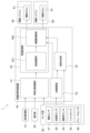
- FIG. 1 is a schematic configuration diagram of a vehicle control device according to an embodiment of the present invention
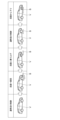
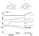
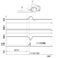
- FIG. 13 is a diagram showing a state in which a vehicle collides against a step and then overcomes the step.
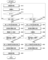
- 5 is a flowchart showing a control process executed by the automatic parking control device according to the present embodiment when the vehicle passes over a step.
- 4 is a flowchart showing a control process executed by the automatic parking control device according to the present embodiment when the vehicle descends from a step.
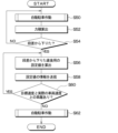
- 4 is a flowchart showing an automatic parking process executed by the automatic parking control device according to the present embodiment.
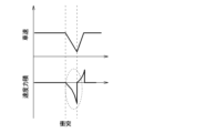
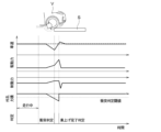
- 10A and 10B are diagrams for explaining a change in velocity impulse when a vehicle collides with a step.
- 10A and 10B are diagrams for explaining a change in the sum of a braking force and a driving force when a vehicle collides with a step.
- 11 is a diagram for explaining a change in disturbance impulse when a wheel collides with a step before starting;
- FIG. 11A and 11B are diagrams for explaining a method of determining when a wheel that has collided with a step before starting has climbed over the step.
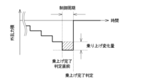
- 10A and 10B are diagrams for explaining a change in disturbance impulse when a vehicle runs over a step.
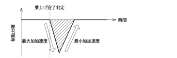
- 10A and 10B are diagrams for explaining braking/driving impulses when a vehicle runs over a step.
- 11 is a diagram for explaining a change in disturbance impulse when a wheel collides against a step during travel.
- FIG. 11 is a diagram for explaining a change in disturbance impulse when a wheel descends from a step.
- FIG. 11 is a diagram for explaining a change in disturbance impulse when a vehicle descends from a step.
- FIG. 10A and 10B are diagrams for explaining braking/driving impulses when a vehicle descends from a step.
- a vehicle control device 1 is applied to an electric vehicle having an automatic parking system.
- the automatic parking system is a control system that automatically parks the vehicle in a parking space.
- the automatic parking system performs an automatic parking process and controls the operation of various control target devices mounted on the vehicle, thereby driving the vehicle and parking it in a parking space.
- the vehicle control device 1 of the present disclosure is configured as one unit with the automatic parking system, and is capable of executing the automatic parking process performed by the automatic parking system.
- the vehicle control device 1 has a periphery monitoring unit 10, an operation unit 20, a sensor unit 30, an automatic parking control device 40, a drive system 50, and a braking system 60.
- the periphery monitoring unit 10, the operation unit 20, the sensor unit 30, the automatic parking control device 40, the drive system 50, and the braking system 60 are used by the vehicle control device 1 to execute the automatic parking process.
- the periphery monitoring unit 10 is an autonomous sensor that monitors the environment around the vehicle and detects moving dynamic targets such as pedestrians and other vehicles, and stationary static targets such as road structures.
- the periphery monitoring unit 10 is configured to include, for example, a camera that captures images of the surroundings of the vehicle, and a sonar that detects objects around the vehicle by emitting ultrasonic waves as search waves and acquiring the reflected waves.
- the periphery monitoring unit 10 may also include a millimeter wave radar that outputs millimeter waves as search waves, or a LIDAR (Light Detection and Ranging) that outputs laser light as search waves.
- the periphery monitoring unit 10 is electrically connected to the automatic parking control device 40, and outputs a signal including the detected information to the automatic parking control device 40 at each predetermined sampling period as sensing information.
- the operation unit 20 is a user interface that enables an operator, such as a driver, to give various instructions to the vehicle control device 1.
- the operation unit 20 includes, for example, an automatic parking start switch that allows the operator to input a signal to start automatic parking.
- the automatic parking start switch is disposed, for example, near the center of the instrument panel.
- the automatic parking start switch may be configured to be displayed on a touch panel display.
- the operation unit 20 is electrically connected to the automatic parking control device 40, and transmits various signals input via the operation unit 20 to the automatic parking control device 40.
- the sensor unit 30 is a sensor that detects various information related to the driving of the vehicle.
- the sensor unit 30 includes a speed sensor 31 that detects the vehicle speed of the vehicle, an acceleration sensor 32 that detects the acceleration of the vehicle, and a steering angle sensor 33 that detects the steering angle of the steering wheel.
- the sensor unit 30 also includes a torque sensor 34 that detects the output torque of the drive system 50 that outputs the driving force for the vehicle, which is an electric vehicle, to drive, and a brake sensor 35 that detects the braking force for braking the vehicle.
- the sensor unit 30 may also include a yaw rate sensor.
- the sensor unit 30 is electrically connected to the automatic parking control device 40, and transmits various information detected by the sensor unit 30 to the automatic parking control device 40.
- the speed sensor 31 is a sensor that detects the speed of the vehicle.
- the speed sensor 31 is composed of a wheel speed sensor that detects the rotation of the wheels of the vehicle.
- the speed sensor 31 is provided near each of the four wheels of the vehicle, and outputs a number of detection signals corresponding to the rotation angle of each of the four wheels as wheel speed pulses.
- the speed sensor 31 outputs a pulse signal a pre-set designed number of times (e.g., 96 times) according to the rotation angle of the wheel every time the wheel rotates once.
- the speed sensor 31 functions as a speed detection unit that outputs information corresponding to the detected vehicle speed.
- the acceleration sensor 32 is a sensor that detects the acceleration of the host vehicle based on the inertial force that accompanies the acceleration of the host vehicle.
- the acceleration sensor 32 is, for example, fixed to the host vehicle, and detects the acceleration in the directions along each of the three axes defined for the host vehicle, specifically, the forward/backward, left/right, and up/down directions of the host vehicle.
- the torque sensor 34 is a sensor that detects the driving force of the vehicle by detecting the output torque of a driving motor (not shown) of the drive system 50.
- the torque sensor 34 When the driver depresses the accelerator pedal, the torque sensor 34 outputs a detection signal corresponding to the output torque of the driving motor that operates according to the amount of depression of the accelerator pedal.
- the torque sensor 34 when the automatic parking system executes automatic parking processing, the torque sensor 34 outputs a detection signal corresponding to the output torque of the driving motor of the drive system 50 that is controlled by the automatic parking processing.
- the brake sensor 35 is a sensor that detects the braking force generated in the braking system 60 when the vehicle is decelerated or stopped. When the driver depresses the brake pedal, the brake sensor 35 outputs a detection signal corresponding to the braking force generated in the braking system 60 according to the amount of depression of the brake pedal. In addition, when the automatic parking system executes the automatic parking process, the brake sensor 35 outputs a detection signal corresponding to the braking force generated in the braking system 60 controlled by the automatic parking process.
- the drive system 50 includes a drive ECU 51, which will be described later.
- the drive system 50 includes, for example, a driving motor (not shown) that functions as a power source for the vehicle, and an inverter that supplies power to the driving motor.
- the drive system 50 controls the output driving force by controlling the power supplied to the inverter to adjust the rotational force of the driving motor that is transmitted to the wheels.
- the braking system 60 includes a braking ECU 61, which will be described later.
- the braking system 60 includes, for example, a brake rotor, brake pads, wheel cylinders, etc., which are not shown.
- the braking system 60 controls the output braking force by adjusting the brake fluid pressure supplied to the wheel cylinders to control the frictional force generated by pressing the brake pads against the brake rotor.
- the braking system 60 controls the braking force generated on each of the four wheels.
- the automatic parking control device 40 is a control device that executes automatic parking processing and controls the operation of various controlled devices when an automatic parking start signal is input.
- the automatic parking control device 40 is composed of a microcomputer including a CPU, ROM, RAM, etc., and its peripheral circuits.
- the automatic parking control device 40 performs various calculations and processing based on the control program stored in the ROM, and controls the operation of various controlled devices connected to its output side.
- the ROM and RAM of the automatic parking control device 40 are composed of non-transient physical storage media.
- the automatic parking control device 40 has a stopping position calculation unit 41, a vehicle speed control unit 42, an impulse calculation unit 43, and a step determination unit 44.
- the automatic parking control device 40 executes a control program stored in the ROM, thereby functioning as the stopping position calculation unit 41, the vehicle speed control unit 42, the impulse calculation unit 43, and the step determination unit 44.
- the automatic parking control device 40 may have multiple circuit modules corresponding to the stopping position calculation unit 41, the vehicle speed control unit 42, the impulse calculation unit 43, and the step determination unit 44.
- the stopping position calculation unit 41 recognizes the surrounding environment of the vehicle based on the sensing information input from the periphery monitoring unit 10, determines a target stopping position as a target position for parking the vehicle, and determines a target driving route to the target stopping position.
- the stopping position calculation unit 41 determines the target stopping position and target driving route based on, for example, image data captured by the camera of the periphery monitoring unit 10, and detection signals including information about objects detected by the sonar, millimeter wave radar, and LIDAR.
- the vehicle speed control unit 42 determines the setting values of each of the controlled devices to be operated in order to stop the vehicle at the target stopping position.
- the vehicle speed control unit 42 has a vehicle speed calculation unit 421 that calculates and determines the setting value of the vehicle speed when the vehicle travels from the current position to the target stopping position, and a braking/driving calculation unit 422 that calculates and determines the driving force and braking force when the vehicle travels from the current position to the target stopping position.
- the vehicle speed calculation unit 421 calculates a target speed, which is a target vehicle speed along the target driving route calculated by the stop position calculation unit 41 when moving the vehicle from the current position to the target stop position.
- the vehicle speed calculation unit 421 transmits information about the calculated target speed to the braking/driving calculation unit 422.
- the driving/braking calculation unit 422 calculates the driving force and braking force required to drive the vehicle at the target speed calculated by the vehicle speed calculation unit 421, and calculates the setting values for each of the controlled devices required to obtain the calculated driving force and braking force.
- the braking/driving calculation unit 422 determines the driving force of the driving motor required to drive the vehicle from the current position to the target stopping position along the target driving route at the target speed as the target rotation speed of the driving motor.
- the braking/driving calculation unit 422 also determines, for example, the target hydraulic pressure of the brake fluid to be supplied to the wheel cylinders provided on each wheel when the vehicle is driven from the current position to the target stopping position along the target driving route at the target speed.
- the braking/driving calculation unit 422 transmits information about the determined driving force to the driving ECU 51 of the driving system 50, and transmits information about the determined braking force to the braking ECU 61 of the braking system 60.
- the drive ECU 51 controls the power supplied to the inverter so that the rotation speed of the driving motor becomes the target rotation speed set by the braking/driving calculation unit 422.
- the drive ECU 51 controls the driving force output by the drive system 50 by controlling the power supplied to the inverter so that the rotation speed of the driving motor approaches the target rotation speed.
- the brake ECU 61 controls the operation of an actuator (not shown) that adjusts the brake fluid pressure so that the brake fluid pressure to the wheel cylinder becomes the target fluid pressure set by the brake/drive calculation unit 422.
- the brake ECU 61 controls the braking force output by the brake system 60 by controlling the actuator so that the brake fluid pressure approaches the target fluid pressure.
- the vehicle control device 1 of this embodiment is equipped with a steering system, and when an automatic parking start signal is input to the automatic parking control device 40, a target steering angle of the steering wheel when driving the vehicle from the current position to the target stopping position along the target driving route is calculated.
- the steering system then controls the operation of a steering motor that rotates the steering wheel so that the steering angle of the steering wheel becomes the target steering angle.
- the automatic parking control device 40 transmits various pieces of information necessary to park the vehicle at the target stopping position to the drive system 50, braking system 60, and steering system.
- the drive system 50 receives various pieces of information from the automatic parking control device 40
- the drive ECU 51 controls the operation of the driving motor so that the output driving force approaches the target driving force determined by the braking/driving calculation unit 422.
- the brake ECU 61 controls the actuator so that the output braking force approaches the target braking force determined by the braking/driving calculation unit 422.
- a step S may be present on the road on which the vehicle V travels.
- the step S has a certain height and impedes the travel of the vehicle V, causing the speed of the vehicle V to decrease when the wheels of the vehicle V collide with the step S while traveling. Furthermore, when the vehicle V starts moving from a state in which the wheels of the vehicle V are in contact with the step S while stopped, the step S prevents the vehicle V from starting, thereby decreasing the acceleration and speed of the vehicle V compared to when the step S is not present.
- the step S increases the speed of the vehicle V when the vehicle V is traveling at a constant speed on a road with a flat road surface or when the vehicle V starts traveling from a stopped state and descends from the step S.
- the reason that the speed of the vehicle V increases when descending from the step S is that when the vehicle V descends from the step S, it is subjected to gravity, and receives a load due to gravity in the vertical direction, i.e., downward in the direction of gravity, thereby converting potential energy into kinetic energy.
- the step S is a source of change that changes the speed of the vehicle V when the wheels of the vehicle V go over the step S or descend from the step S.
- the braking/driving calculation unit 422 sets a larger setting value for the driving force for the wheels to go over the step S compared to when the step S does not exist. Also, when calculating the braking force required to make the vehicle V go over the step S, the braking/driving calculation unit 422 sets a smaller setting value for the braking force when the vehicle V goes over the step S compared to when the step S does not exist.
- the braking/driving calculation unit 422 is required to set the driving force setting value immediately after the wheel runs over the step S to be smaller than that before the wheel runs over the step S, or to set the braking force setting value immediately after the wheel runs over the step S to be larger than that before the wheel runs over the step S.
- the braking/driving calculation unit 422 is required to set the driving force immediately after the wheel descends the step S to a smaller value compared to before the wheel descends the step S, or to set the braking force immediately after the wheel descends the step S to a larger value compared to before the wheel descends the step S.
- the vehicle control device 1 of this embodiment accurately determines the passing of the step S and appropriately controls the driving force and braking force of the vehicle V immediately after passing over the step S.
- the vehicle control device 1 of this embodiment has a step determination unit 44 that determines the passing of the step S, and an impulse calculation unit 43 that determines the information required for the step determination unit 44 to determine the passing of the step S and to determine the driving force and braking force immediately after passing over the step S.
- the step determination unit 44 detects that the wheel of the vehicle V has collided with the step S when the wheel of the vehicle V in motion collides with the step S, and detects that the wheel of the vehicle V in motion is in contact with the step S when the vehicle V starts moving from a state where the wheel is in contact with the step S.
- the step determination unit 44 also detects that the wheel of the vehicle V in motion has climbed up on the step S after colliding with the step S and that the wheel of the vehicle V in motion has climbed up on the step S after starting moving with the wheel in contact with the step S.
- the step determination unit 44 also detects that the wheel of the vehicle V in motion has climbed up on the step S when the wheel of the vehicle V in motion descends from the step S.
- the step determination unit 44 determines whether the wheel has passed the step S based on information acquired from the impulse calculation unit 43.
- the step determination unit 44 in this embodiment functions as a passage determination unit that determines the passage of the step S, which is a change source. The determination method will be described in detail later.
- the impulse calculation unit 43 calculates the impulse applied to the vehicle V by passing over the step S, as information required by the step determination unit 44 when performing these detections. Furthermore, the impulse calculation unit 43 calculates the impulse applied to the vehicle V by passing over the step S, as information required by the braking/driving calculation unit 422 when appropriately calculating the driving force and braking force of the vehicle V immediately after passing over the step S. The impulse calculation unit 43 calculates the impulse applied to the vehicle V by passing over the step S based on various information transmitted from the sensor unit 30, and transmits impulse information corresponding to the calculated impulse to the step determination unit 44 and the braking/driving calculation unit 422. Details of the method of calculating the impulse and the method of calculating the driving force and braking force immediately after passing over the step S will be described later.
- the control process shown in FIG. 3 and FIG. 4 is executed periodically, for example, when the automatic parking start switch is operated by the operator and an automatic parking start signal is input to the vehicle control device 1, and ends when the vehicle V is parked and the automatic parking process is completed.
- the control process shown in FIG. 3 and FIG. 4 also includes a control process executed when the vehicle V passes over a step S.
- control process shown in FIG. 3 includes a control process executed after the vehicle V climbs up the step S from a state before the vehicle V climbs up the step S.
- control process shown in FIG. 4 includes a control process executed after the vehicle V descends from a state in which the vehicle V climbs up the step S.
- the control processes shown in FIG. 3 and FIG. 4 may be executed in parallel, or the control process shown in FIG. 4 may be executed after the control process shown in FIG. 3 is executed. In this embodiment, an example in which the control processes shown in FIG. 3 and FIG. 4 are executed in parallel will be described.
- control process including the control process executed after the vehicle V has climbed over the step S from a state before the vehicle V has climbed over the step S will be described with reference to Figures 3 and 5.
- step S10 the automatic parking control device 40 starts the automatic parking operation. Specifically, as shown in FIG. 5, first, in step S100, the automatic parking control device 40 acquires sensing information from the periphery monitoring unit 10. For example, the automatic parking control device 40 acquires imaging data from a camera as sensing information, and acquires information on objects present within the detection ranges of the sonar, millimeter wave radar, and LIDAR from the sonar, millimeter wave radar, and LIDAR.
- step S110 the automatic parking control device 40 recognizes the surrounding environment of the vehicle based on various information acquired by the stopping position calculation unit 41 from the surroundings monitoring unit 10, and determines the target stopping position and the target driving route.
- the vehicle speed control unit 42 determines the setting values of each of the controlled devices to be operated in order to stop the host vehicle at the target stop position. Specifically, the vehicle speed calculation unit 421 determines a target speed for moving the host vehicle V from the current position to the target stop position along the target driving route determined by the stop position calculation unit 41. Then, the braking/driving calculation unit 422 determines the driving force required to drive the host vehicle at the target speed determined by the vehicle speed calculation unit 421 along the target driving route determined by the stop position calculation unit 41. The braking/driving calculation unit 422 also determines the braking force required to drive the host vehicle at the target speed determined by the vehicle speed calculation unit 421 along the target driving route determined by the stop position calculation unit 41. Furthermore, the braking/driving calculation unit 422 determines the target steering angle of the steering wheel required to drive the host vehicle along the target driving route.
- step S130 the automatic parking control device 40 transmits information on the various setting values calculated by the braking/driving calculation unit 422 to the drive system 50, the braking system 60, and the steering system.
- the braking/driving calculation unit 422 transmits information on the driving force to the drive ECU 51 of the drive system 50, transmits information on the determined braking force to the braking ECU 61 of the braking system 60, and transmits information on the determined steering angle to the steering system.
- the driving motor that outputs the driving force, the actuator that adjusts the brake fluid pressure that outputs the braking force, and the steering motor that controls the steering angle all start operating, and automatic parking is performed.
- step S140 the automatic parking control device 40 determines whether the current position of the vehicle V is the target stopping position. If the automatic parking control device 40 determines that the current position of the vehicle V is the target stopping position, it determines that the vehicle has traveled to the target stopping position and ends the automatic parking process. The automatic parking control device 40 repeatedly executes the processes of steps S100 to S140 until it determines in step S140 that the current position of the vehicle V is the target stopping position. In other words, the automatic parking operation continues until it is determined in step S140 that the host vehicle has traveled to the target stopping position.
- a step S as shown in FIG. 2 exists on the road on which the vehicle V is traveling, the wheels of the vehicle V may come into contact with or collide with the step S.
- the wheels of the vehicle V may collide with the step S.
- the wheels will be in collision with the step S before starting off, i.e., the wheels of the stopped vehicle V will be in contact with the step S.
- a driving force greater than that required before the collision with the step S may be required to overcome the step S.
- a driving force greater than that required when the step S does not exist is required to overcome the step S.
- the driving force after the step S has been overcome must be reduced from the driving force set large for overcoming the step S.
- the braking force after the step S has been overcome must be increased from the braking force before the step S has been overcome.
- the automatic parking control device 40 of this embodiment executes the process from step S12 onwards during automatic parking operation in the control process shown in FIG. 3, and determines whether the wheels are in contact with or colliding with the step S before the vehicle V runs over the step S. If the wheels are in contact with or colliding with the step S, the automatic parking control device 40 sets the drive force setting value to a value that allows the vehicle to overcome the step S, and reduces the drive force after the step S has been overcome.
- the control process from step S12 onwards will be described below.
- step S12 during automatic parking operation, the automatic parking control device 40 uses the impulse calculation unit 43 to calculate the impulse applied to the vehicle V. Then, in steps S16 and S32, the automatic parking control device 40 uses the step determination unit 44 to determine whether or not the wheels of the vehicle V are in contact with or colliding with the step S based on the impulse calculated by the impulse calculation unit 43.
- the impulse calculation unit 43 calculates the impulse applied to the vehicle V when the vehicle V passes over the step S, based on various information acquired from the sensor unit 30.
- the impulse applied to the vehicle V will be described with reference to Figures 6 and 7.
- the impulse applied to the vehicle V can be calculated based on the speed at which the vehicle V travels, i.e., the vehicle speed.
- the impulse calculated based on the vehicle speed will be referred to as the speed impulse.
- the speed impulse applied to the vehicle V when the vehicle V travels on the road surface for a predetermined period of time can be calculated by integrating the value obtained by multiplying the weight of the vehicle V and the acceleration of the vehicle V. For example, when the weight of the vehicle V is the vehicle weight M and the acceleration of the vehicle V is the vehicle acceleration a, the speed impulse can be calculated by the following formula 1.
- the impulse calculation unit 43 calculates the speed impulse using the following formula 1 as impulse information.
- Speed impulse ⁇ (vehicle weight M ⁇ vehicle acceleration a)
- vehicle speed impulse ⁇ (vehicle weight M ⁇ vehicle acceleration a)
- the speed impulse is smaller than 0 while the vehicle speed is decreasing, and is larger than 0 while the vehicle speed is increasing. Note that when the vehicle speed is constant and is not accelerating or decelerating, and when the vehicle V is stopped, the vehicle acceleration a is 0. In this case, the speed impulse is 0.
- the impulse calculation unit 43 obtains information on the vehicle acceleration a from the sensor unit 30 to calculate the speed impulse.
- the vehicle acceleration a to calculate the speed impulse may use information on the acceleration detected by the acceleration sensor 32 of the sensor unit 30, or may use a differential value obtained by differentiating the speed detected by the speed sensor 31.
- the impulse calculation unit 43 uses the differential value of the speed detected by the speed sensor 31 as the vehicle acceleration a.
- a preset design value may be used for the vehicle weight M.
- the magnitude of the velocity impulse decreases as the vehicle speed decreases. Therefore, when a wheel of a vehicle V traveling on a road surface collides with a step S and the vehicle speed decreases, the velocity impulse becomes smaller than before the collision with the step S.
- the set value of the driving force set by the braking/driving calculation unit 422 in order to overcome the step S may need to be increased from the set value set in step S120 of the previous control cycle. Also, in order to avoid a sudden increase in vehicle speed immediately after the wheels run up onto the step S due to the increased driving force, the set value of the driving force set by the braking/driving calculation unit 422 may need to be reduced by the increased set value in order to overcome the step S.
- the braking/driving calculation unit 422 may need to change the set value of the driving force, so it is necessary to accurately detect that the wheel has collided with the step S. Also, in order for the braking/driving calculation unit 422 to reduce the set value of the driving force immediately after the wheel has climbed up on the step S, it is necessary to accurately detect that the wheel has climbed up on the step S after colliding with it.
- step S will prevent the vehicle V from traveling. For this reason, when the vehicle V starts moving and goes over the step S, it may be necessary to increase the set value of the driving force set by the braking/driving calculation unit 422 to go over the step S from the set value set in step S120 of the previous control cycle.
- the braking/driving calculation unit 422 may need to change the set value of the driving force, so it is necessary to accurately detect that the wheels are in contact with the step S before starting.
- step S When vehicle V starts moving with its wheels in contact with step S, the vehicle speed is 0 until vehicle V starts moving, that is, until the wheels start climbing up step S. Therefore, the speed impulse does not change from 0 until the wheels start climbing up step S. Then, when vehicle V starts moving and the wheels start climbing up step S, the speed impulse increases from 0.
- the velocity impulse has a magnitude of 0 until the vehicle V starts moving, regardless of whether the wheel is in contact with the step S or not, and increases from 0 when the vehicle V starts moving.
- the method of detecting the change in the speed impulse cannot accurately detect that the wheel is in contact with the step S before starting. Furthermore, even if an increase in the speed impulse is detected, it is not possible to determine whether the vehicle V started from a state in which the wheel was in contact with the step S, or whether the vehicle V started from a state in which the wheel was not in contact with the step S.
- the driving force and braking force are different when the speed impulse is reduced due to the collision of the wheels with the step S and when the speed impulse is reduced due to the driver's braking operation. Therefore, based on the difference between the driving force and the braking force, it is possible to accurately detect whether the wheels of the vehicle V are in contact with or colliding with the step S.
- the difference between the driving force and the braking force when the speed impulse is reduced due to the collision of the wheels with the step S and when the speed impulse is reduced due to the driver's braking operation will be explained with reference to Figure 7.
- the vehicle speed control unit 42 adjusts the driving force and braking force to drive the vehicle at a target speed.
- the braking/driving calculation unit 422 sets the set value of the driving force to a value equal to or greater than the set value of the braking force.
- the braking/driving calculation unit 422 sets the set value of the braking force to a value greater than the set value of the driving force.
- the automatic parking control device 40 repeatedly executes the processing of steps S100 to S140, causing the braking/driving calculation unit 422 to increase the set value of the driving force and decrease the set value of the braking force so that the vehicle speed approaches the target speed.
- the braking/driving calculation unit 422 gradually increases the set value of the driving force and gradually increases the set value of the braking force as the speed impulse gradually decreases. Therefore, as shown in FIG. 7, when the speed impulse decreases due to a wheel hitting a step S, the total value obtained by adding the driving force output by the driving system 50 and the braking force output by the braking system 60 increases as the speed impulse decreases. This is because when attempting to accelerate the vehicle V, the braking/driving calculation unit 422 sets the set value of the driving force greater than the set value of the braking force.
- the driving force and braking force are different when the speed impulse is reduced due to the collision of the wheels with a step S and when the speed impulse is reduced due to the driver's braking operation.
- the impulse applied to the vehicle V can be calculated based on the driving force and braking force, in addition to being calculated based on the vehicle speed.
- the braking/driving impulse when the vehicle speed changes as a result of going over a step S, a difference occurs between the speed impulse that can be calculated based on the vehicle speed and the impulse that can be calculated based on the driving force and braking force. Furthermore, even when the vehicle V is started from a state in which the wheels are in contact with a step S, a difference occurs between the speed impulse that can be calculated based on the vehicle speed and the impulse that can be calculated based on the driving force and braking force.
- the impulse that can be calculated based on the driving force and braking force will be referred to as the braking/driving impulse.
- the driving/braking impulse is the impulse applied to the vehicle V, and can also be calculated based on the driving force output by the drive system 50 and the braking force output by the braking system 60 in order for the vehicle V to travel.
- the impulse calculation unit 43 calculates the driving/braking impulse in addition to the speed impulse.
- the driving/braking impulse applied to the vehicle V when the vehicle V runs on a road surface for a predetermined period of time can be calculated by integrating the value obtained by adding the driving force output by the drive system 50 and the braking force output by the braking system 60.
- the driving/braking impulse can be calculated by the following formula 2.
- the impulse calculation unit 43 calculates the driving/braking impulse using the following formula 2 as impulse information.
- the driving/braking impulse becomes greater than 0.
- the driving/braking impulse becomes greater than 0.
- the driving/braking impulse is 0.
- the driving force F1 may be calculated based on a set value set by the braking/driving calculation unit 422, i.e., the target rotation speed of the driving motor, or based on the measured value of the output torque of the driving motor detected by the torque sensor 34.
- the braking force F2 may be calculated based on a set value set by the braking/driving calculation unit 422, i.e., the target hydraulic pressure of the brake fluid supplied to the wheel cylinder.
- the braking force F2 may be calculated based on the measured value of the braking force generated in the braking system 60 detected by the brake sensor 35.
- the measurement values detected by the torque sensor 34 and the brake sensor 35 are used, rather than using the respective set values of the driving force and braking force set by the driving/braking calculation unit 422, thereby making it possible to reduce errors in the calculated driving/braking impulse.
- the braking/driving impulse increases in magnitude when the vehicle V accelerates, and decreases in magnitude when the vehicle V decelerates.
- the speed impulse and the braking/driving impulse are approximately equal in magnitude.
- the speed impulse and the braking/driving impulse are approximately equal in magnitude. This is because, when not affected by an external disturbance, changes in vehicle speed are determined by changes in driving force and braking force.
- the speed impulse decreases as the vehicle speed decreases.
- the driving/braking impulse is not affected by the change in vehicle speed even when the wheel collides with a step S and the vehicle speed decreases, as long as the driving force and braking force do not decrease.
- the driving/braking impulse will increase in magnitude if the value obtained by adding the driving force and braking force changes to become larger.
- the velocity impulse and the braking/driving impulse will differ in magnitude.
- the magnitude of the velocity impulse will deviate from the magnitude of the braking/driving impulse.
- the magnitude of the velocity impulse and the magnitude of the braking/driving impulse will deviate due to the impulse received from the external disturbance.
- the speed impulse is zero when the vehicle V is stopped. For this reason, when starting the vehicle V from a state in which the wheels of the vehicle V have collided with a step S, even if the driving force is increased to start the vehicle V, the speed impulse is zero until the vehicle V starts traveling. In contrast, the magnitude of the braking/driving impulse increases from zero even when the vehicle V is stopped, by increasing the driving force to start the vehicle V.
- the speed impulse and the braking/driving impulse will be different in magnitude.
- the magnitude of the braking/driving impulse will deviate from the magnitude of the speed impulse.
- the magnitude of the speed impulse and the magnitude of the braking/driving impulse will deviate due to the impulse received from the disturbance.
- the impulse received from the step S which is a cause of disturbance, when the wheel of the vehicle V traveling on the road surface collides with a step S and when the vehicle V starts from a state in which the wheel has collided with the step S, will be referred to as the disturbance impulse.
- the disturbance impulse can be calculated by subtracting the braking/driving impulse from the speed impulse, as shown in the following formula 3.
- the impulse calculation unit 43 calculates the speed impulse and the braking/driving impulse
- the step determination unit 44 determines whether or not the vehicle is in a state of collision with the step S and contact with the step S based on the speed impulse and the braking/driving impulse calculated by the impulse calculation unit 43.
- a method of determining whether or not the vehicle is in a state of collision with the step S and whether or not the wheel is in contact with the step S before starting will be described with reference to Figs. 3, 8, and 9.
- the impulse calculation unit 43 calculates the speed impulse and braking/driving impulse applied to the vehicle V when passing over the step S, based on various information acquired from the sensor unit 30. Specifically, the impulse calculation unit 43 differentiates the detection value detected by the speed sensor 31 to obtain the acceleration of the vehicle V, and calculates the speed impulse based on the obtained acceleration of the vehicle V and the preset weight of the vehicle V. The impulse calculation unit 43 also calculates the braking/driving impulse based on the output torque of the driving motor detected by the torque sensor 34 and the braking force generated in the braking system 60 detected by the brake sensor 35. The impulse calculation unit 43 transmits the calculated speed impulse information and braking/driving impulse information to the step determination unit 44 and the braking/driving calculation unit 422.
- the step determination unit 44 determines whether or not the vehicle V is moving based on the information acquired from the sensor unit 30. For example, if the detection value detected by the speed sensor 31 is not 0, the step determination unit 44 determines that the vehicle V is moving, and if the detection value detected by the speed sensor 31 is 0, the step determination unit 44 does not determine that the vehicle V is moving. If the step determination unit 44 does not determine that the vehicle V is moving, it executes the process of step S16, and if it determines that the vehicle V is moving, it executes the process of step S32.
- step S16 the step determination unit 44 determines whether or not the wheels of the vehicle V before starting are in contact with the step S based on the speed impulse information and the braking/driving impulse information received from the impulse calculation unit 43. Specifically, the step determination unit 44 calculates a disturbance impulse, which is the difference between the speed impulse and the braking/driving impulse, based on the speed impulse information and the braking/driving impulse information, and determines whether or not the wheels of the vehicle V before starting are in contact with the step S based on the calculated disturbance impulse. Then, if it is determined that the wheels of the vehicle V before starting are in contact with the step S, the automatic parking control device 40 executes the processing from step S18 onwards.
- a disturbance impulse which is the difference between the speed impulse and the braking/driving impulse
- step S32 the step determination unit 44 determines whether or not a wheel of the moving vehicle V has collided with a step S based on the speed impulse information and the braking/driving impulse information received from the impulse calculation unit 43. Specifically, the step determination unit 44 calculates a disturbance impulse, which is the difference between the speed impulse and the braking/driving impulse, based on the speed impulse information and the braking/driving impulse information, and determines whether or not a wheel of the moving vehicle V has collided with a step S based on the calculated disturbance impulse. Then, if it is determined that a wheel of the moving vehicle V has collided with a step S, the automatic parking control device 40 executes the processing from step S34 onwards.
- a disturbance impulse which is the difference between the speed impulse and the braking/driving impulse
- step determination unit 44 determines whether or not the wheels of the vehicle V before starting are in contact with the step S based on the disturbance impulse, and the control process when it is determined that the wheels of the vehicle V before starting are in contact with the step S will be described with reference to FIG. 8.
- the vehicle speed and driving force are 0. Also, when the vehicle V is stopped before starting, the braking system 60 outputs a braking force to stop the vehicle V.
- automatic parking is started based on the various set values calculated by the braking/driving calculation unit 422.
- the target speed is set so that the vehicle speed gradually increases over time.
- the set value of the driving force is set so that it gradually increases over time in order to bring the vehicle speed closer to the target speed. This causes the traveling system to output the driving force.
- the dashed line indicates the target speed
- the solid line indicates the speed of the vehicle V detected by the speed sensor 31.
- the set value of the braking force is set to 0. This causes the braking system 60 to stop outputting the braking force.
- step S prevents vehicle V from starting, so that even if the travel motor outputs driving force, vehicle V cannot start due to step S, which is a disturbance.
- the vehicle speed remains at 0 immediately after the travel motor outputs driving force. Therefore, while step S prevents vehicle V from starting, the speed impulse remains at 0.
- the step S prevents the vehicle V from starting, the vehicle speed detected by the speed sensor 31 will diverge from the target speed. The amount of deviation between the vehicle speed detected by the speed sensor 31 and the target speed will gradually increase over time. For this reason, the braking/driving calculation unit 422 gradually increases the set value of the driving force over time. As a result, the driving force output by the drive system 50 will gradually increase over time. The braking/driving impulse will increase over time.
- the disturbance impulse calculated by subtracting the driving/braking impulse from the velocity impulse, decreases away from 0 over time, as shown in Figure 8.
- the absolute value of the disturbance impulse increases over time.
- step S16 when the disturbance impulse becomes equal to or less than a preset contact judgment threshold, the step judgment unit 44 judges that the wheels of the vehicle V before starting are in contact with the step S.
- the step judgment unit 44 judges that the wheels of the vehicle V before starting are in contact with the step S.
- the contact determination threshold is a predetermined threshold that is set in advance to determine whether or not the vehicle V is in contact with the step S, and is set, for example, based on experimental results obtained by conducting an experiment in advance in which the vehicle V is started with the wheels in contact with the step S. Furthermore, the contact determination threshold is set in step S16 according to the height of the step S with which it is desired to detect whether the wheels are in contact.
- the vehicle control device 1 of this embodiment can accurately detect that the wheels of the vehicle V are in contact with the step S before starting by determining that the wheels of the vehicle V are in contact with the step S before starting based on the disturbance impulse. It can then detect that the vehicle V has started from a state in which the wheels are in contact with the step S.
- the contact determination threshold in this embodiment is set to be changeable depending on the roughness of the road surface.
- the step determination unit 44 has a base threshold that serves as a reference threshold set in advance, and the contact determination threshold is set to be changeable by adding a predetermined additional value to the base threshold depending on the roughness of the road surface.
- the base threshold is set, for example, depending on the height of the step S.
- the contact determination threshold is set so that it can be changed between a good road threshold to which a predetermined additional value is added when the road surface is flat, and a bad road threshold to which a predetermined additional value is added when the road surface is uneven and rougher than flat, depending on the roughness of the road surface.
- the predetermined additional value added when setting the good road threshold is set to be smaller than the predetermined additional value added when setting the bad road threshold. In other words, the good road threshold is smaller than the bad road threshold.
- the step determination unit 44 detects the roughness of the road surface and sets the contact determination threshold to either the good road threshold or the bad road threshold.
- the step determination unit 44 may detect the roughness of the road surface based on the speed of the vehicle V detected by the speed sensor 31 when it last traveled before the vehicle V stopped traveling. For example, if the deviation between the speed of the vehicle V detected by the speed sensor 31 when it last traveled and the target speed when it last traveled is relatively small, the step determination unit 44 determines that the roughness of the road surface is flat and sets the contact determination threshold to the good road threshold. On the other hand, if the deviation between the speed of the vehicle V detected by the speed sensor 31 when it last traveled and the target speed when it last traveled is relatively large, the step determination unit 44 determines that the roughness of the road surface is uneven and sets the contact determination threshold to the bad road threshold that is larger than the good road threshold.
- the reason that the roughness of the road surface can be determined based on the deviation between the speed of the vehicle V detected by the speed sensor 31 and the target speed is that when the road surface is flat, the resistance that the vehicle V receives from the road surface when traveling on the road surface is smaller than when the road surface is uneven. In other words, when the resistance from the road surface is small, it is easier to bring the speed of the vehicle V closer to the target speed.
- the step determination unit 44 may detect the roughness of the road surface based on information other than the speed of the vehicle V detected by the speed sensor 31. For example, the step determination unit 44 may detect the roughness of the road surface based on the vertical acceleration of the vehicle V detected by the acceleration sensor 32. In this case, the step determination unit 44 may determine that the roughness of the road surface is flat and set the contact determination threshold to the good road threshold if, for example, the vertical acceleration of the vehicle V detected by the acceleration sensor 32 when it was last driven is equal to or less than a predetermined value.
- the step determination unit 44 may determine that the roughness of the road surface is uneven and set the contact determination threshold to the bad road threshold if, for example, the vertical acceleration of the vehicle V detected by the acceleration sensor 32 when it was last driven is greater than a predetermined value.
- the step determination unit 44 may also detect the roughness of the road surface based on an image of the road surface captured by the camera of the periphery monitoring unit 10, or based on reflected waves from the road surface acquired by each of the sonar, millimeter wave radar, and LIDAR of the periphery monitoring unit 10.
- step determination unit 44 determines in step S16 that the wheels of the vehicle V before starting are in contact with the step S, it transmits information on the determination result to the braking/driving calculation unit 422.
- the step determination unit 44 receives information that the wheels of the vehicle V before starting are in contact with the step S, the braking/driving calculation unit 422 executes the process of step S18.
- step S18 the braking/driving calculation unit 422 calculates the driving force required to overcome the step S based on the determination result of the step determination unit 44. For example, the braking/driving calculation unit 422 calculates the driving force required to overcome the step S as a value obtained by increasing the set value set in step S120 of the immediately preceding control cycle in the automatic parking operation by a preset increase amount.
- step S20 the braking/driving calculation unit 422 transmits information about the calculated driving force required to overcome the step S to the driving ECU 51 of the driving system 50.
- the driving force output by the driving motor becomes greater than the set value that was set when the automatic parking start signal was input.
- the step determination unit 44 detects the number of pulse signals based on the pulse signals output by the speed sensor 31. After it is determined in step S16 that the wheel is in contact with the step S, the step determination unit 44 detects the number of pulse signals received from the speed sensor 31. Then, the step determination unit 44 determines whether the wheel of the vehicle V has climbed over the step S based on whether the number of received pulse signals is equal to or exceeds a predetermined determination number.
- the speed sensor 31 outputs a pulse signal as shown in FIG. 9 a designed number of times according to the rotation angle of the wheel each time the wheel rotates once. Therefore, the rotation angle of the wheel can be obtained based on the number of pulse signals. And, based on the rotation angle of the wheel, the travel distance of the vehicle V can be obtained. Therefore, the step determination unit 44 can determine whether the vehicle V has traveled and climbed up onto a step S based on the number of detected pulse signals. Note that the pulse width of the pulse signal becomes smaller the faster the rotation speed of the wheel.
- the number of judgments for determining whether or not the wheel of the vehicle V has run up the step S is set to three. Therefore, the step judgment unit 44 judges that the wheel has run up the step S when it receives three pulse signals from the speed sensor 31 after it has been determined that the wheel is in contact with the step S.
- the number of judgments for determining whether or not the wheel of the vehicle V has run up the step S is not limited to three, and may be less than three or more than three. The more judgments there are, the longer it takes to determine that the wheel has run up the step S when the wheel rotates, but it is possible to avoid erroneous judgments due to wheel spinning, etc.
- the step determination unit 44 may determine that a wheel has run up a step S when it receives a determined number of pulse signals from two of the four speed sensors 31.
- the step determination unit 44 may determine that a wheel has run up a step S when it receives a determined number of pulse signals from all four speed sensors 31.
- the automatic parking control device 40 repeatedly executes the processes of steps S18 to S24 until it is determined that the wheels of the vehicle V have climbed up onto the step S. Then, in step S24, when the step determination unit 44 determines that the wheels of the vehicle V have climbed up onto the step S, it transmits information on the determination result to the braking/driving calculation unit 422. When the braking/driving calculation unit 422 receives information from the step determination unit 44 that the wheels have climbed up onto the step S, it executes the process of step S26.
- the vehicle control device 1 of this embodiment can accurately detect that the wheels of the vehicle V, which have been in contact with the step S before starting, have climbed up onto the step S by determining that the wheels have climbed up onto the step S based on the number of pulse signals received from the speed sensor 31.
- step S26 the braking/driving calculation unit 422 calculates the driving force immediately after running over the step S and the braking force immediately after running over the step S based on the judgment result of the step judgment unit 44 and the speed impulse information and the braking/driving impulse information calculated by the impulse calculation unit 43.
- the braking/driving calculation unit 422 calculates a value that is the driving force immediately after running over the step S, which is reduced by a preset reduction amount from the driving force set in step S18 to get over the step S.
- the braking/driving calculation unit 422 sets the set value of the driving force immediately after running over the step S to 0.
- step S26 immediately after running over the step S is insufficient or the reduction in driving force is insufficient compared to the driving force calculated in step S18 to run over the step S, there is a risk that the vehicle speed will suddenly increase after running over the step S. Also, if the braking force calculated in step S26 immediately after running over the step S is excessive compared to the driving force calculated in step S18 to run over the step S, there is a risk that the vehicle V will decelerate more than necessary after running over the step S.
- the braking/driving calculation unit 422 appropriately calculates the braking force and driving force immediately after running over the step S so that the braking force and driving force after running over the step S are not excessive or insufficient.
- the automatic parking control device 40 increases the driving force by a preset increment for each control cycle by repeatedly executing the processes of steps S18 to S24 until it is determined that the wheels of the vehicle V have climbed up onto the step S. Then, the disturbance impulse calculated by subtracting the braking/driving impulse from the speed impulse decreases and moves away from 0 over time, as shown in FIG. 10. Specifically, the disturbance impulse decreases in a stepped manner so that its absolute value increases over time.
- the disturbance impulse calculated by subtracting the braking/driving impulse from the speed impulse has a larger absolute value as the braking/driving impulse increases.
- the setting value of the braking force when executing the automatic parking process is set to 0. Therefore, the disturbance impulse, which decreases so that its absolute value increases in a stepped manner, changes for each control cycle according to the amount of change in the driving force, which increases by a preset increment.
- the disturbance impulse calculated when it is determined that the wheels of the vehicle V have climbed up onto the step S is the disturbance impulse immediately after the vehicle V climbs up onto the step S.
- the disturbance impulse calculated in the control cycle immediately before the timing at which it is determined that the wheels of the vehicle V have climbed up onto the step S is the disturbance impulse immediately before the vehicle V climbs up onto the step S.
- the disturbance impulse calculated when it is determined that the wheels of the vehicle V have climbed up onto the step S is the disturbance impulse when the driving force calculated by the braking/driving calculation unit 422 becomes equal to or greater than the driving force required to climb over the step S.
- the disturbance impulse calculated in the control cycle immediately before the timing when it is determined that the wheels of the vehicle V have climbed up onto the step S is the disturbance impulse immediately before the timing when the driving force calculated by the braking/driving calculation unit 422 becomes equal to or greater than the driving force required to climb over the step S.
- the difference between the disturbance impulse calculated when it is determined that the wheels of the vehicle V have run up onto the step S and the disturbance impulse calculated immediately before it is determined that the wheels of the vehicle V have run up onto the step S is the amount of change in the disturbance impulse that decreases with each control cycle.
- the difference between the disturbance impulse when it is determined that the wheels of the vehicle V have run up onto the step S and the disturbance impulse immediately before it is determined that the wheels of the vehicle V have run up onto the step S is the amount of change in the impulse received from the step S, which becomes a disturbance when the vehicle V runs up onto the step S.
- This difference in disturbance impulse is the surplus disturbance impulse component that causes the vehicle speed of the vehicle V to suddenly increase when the vehicle V runs up onto the step S.
- the braking force and driving force after climbing over the step S are required to be set based on the difference between the disturbance impulse when it is determined that the step S has been climbed and the disturbance impulse immediately before it is determined that the step S has been climbed.
- the difference between the disturbance impulse obtained when it is determined that the wheels of the vehicle V have climbed over the step S and the disturbance impulse obtained immediately before it is determined that the wheels of the vehicle V have climbed over the step S will be referred to as the climb-over change amount.
- the braking/driving calculation unit 422 calculates the braking force and driving force immediately after the wheels of the vehicle V run over the step S based on the amount of change in the run-up. In other words, the braking/driving calculation unit 422 calculates the braking force and driving force immediately after the vehicle V passes over the step S based on the amount of change in the disturbance impulse when passing over the step S.
- the braking/driving calculation unit 422 sets the set value of the driving force immediately after the wheel runs over the step S as close to 0 as possible to prevent the vehicle V from suddenly accelerating immediately after the wheel runs over the step S.
- the braking/driving calculation unit 422 increases the setting value of the braking force immediately after the wheel runs over the step S from 0, and then reduces the braking force to 0 so that the vehicle speed approaches the target speed. Therefore, the braking/driving impulse based on the braking force and driving force set by the braking/driving calculation unit 422 gradually increases as the braking force increases immediately after it is determined that the wheel has run over the step S, and then gradually decreases as the braking force decreases, as shown in FIG. 11.
- the braking/driving calculation unit 422 of this embodiment calculates the braking force immediately after climbing over the step S so that the difference between the absolute value of the braking/driving impulse immediately after climbing over the step S and the absolute value of the climbing change approaches zero. Specifically, the braking/driving calculation unit 422 calculates the braking force immediately after climbing over the step S so that the absolute value of the braking/driving impulse immediately after climbing over the step S is equal to the absolute value of the climbing change.
- the absolute value of the braking/driving impulse immediately after running over the step S is the braking/driving impulse component shown by the diagonal hatching in FIG. 11.
- the running-over change amount which is the difference between the disturbance impulse calculated when it is determined that the wheels of the vehicle V have run over the step S and the disturbance impulse calculated immediately before it is determined that the wheels of the vehicle V have run over the step S, is the disturbance impulse component shown by the diagonal hatching in FIG. 10.
- the braking/driving calculation unit 422 of this embodiment sets the braking force immediately after running over the step S so that the area of the portion of the disturbance impulse shown in FIG. 10 shown by the diagonal hatching is equal to the area of the portion of the braking/driving impulse shown in FIG. 11 shown by the diagonal hatching.
- the braking/driving calculation unit 422 transmits information about the calculated braking force to the braking system 60, and changes the braking force quickly so that the braking force output by the braking system 60 becomes the calculated set value.
- the maximum amount of change in acceleration of vehicle V per unit time that can be changed by the braking force output by braking system 60 is limited in advance by the performance of braking system 60.
- the jerk of vehicle V that decreases as the braking force is increased and the jerk of vehicle V that increases as the braking force is decreased are limited by the performance of braking system 60.
- the maximum value of the acceleration per unit time of the vehicle V that decreases as the braking force output by the braking system 60 increases is defined as the maximum jerk.
- the minimum value of the acceleration per unit time of the vehicle V that increases as the braking force output by the braking system 60 decreases is defined as the minimum jerk.
- the maximum jerk and minimum jerk are determined in advance based on the characteristics of an actuator (not shown) of the braking system 60 that adjusts the brake fluid pressure.
- the braking/driving calculation unit 422 of this embodiment sets the braking force so that when the vehicle V is decelerated by increasing the braking force immediately after running over a step S, the amount of decrease in acceleration of the vehicle V per unit time is the maximum jerk. Also, when the vehicle V is decelerated immediately after running over a step S and then accelerated, the braking/driving calculation unit 422 sets the braking force so that the amount of increase in acceleration of the vehicle V per unit time is the minimum jerk.
- step S28 the braking/driving calculation unit 422 transmits information about the calculated driving force immediately after running over the step S to the driving ECU 51 of the driving system 50, and transmits information about the calculated braking force immediately after running over the step S to the braking ECU 61 of the braking system 60.
- the driving force output by the drive system 50 becomes smaller than the set value set in step S18. Specifically, the driving force output by the drive system 50 immediately after climbing over the step S becomes 0, as shown in FIG. 8.
- the braking force output by the braking system 60 becomes greater than the set value set in step S18.
- the driving force output by the braking system 60 immediately after the vehicle V runs over the step S gradually increases over time, as shown in FIG. 8.
- step S30 the automatic parking control device 40 controls the vehicle V for a predetermined time with the driving force and braking force set in step S26, and then returns to the control before it was determined that the wheels of the vehicle V were in contact with the step S before starting.
- the automatic parking control device 40 performs the processes of steps S100 to S140 and performs the automatic parking operation.
- step determination unit 44 determines whether or not a wheel of a traveling vehicle V has collided with a step S based on the disturbance impulse, and the control process when it is determined that a wheel of a traveling vehicle V has collided with a step S will be described with reference to FIG. 12.
- the vehicle speed detected by the speed sensor 31 diverges from the target speed.
- the amount of deviation between the vehicle speed detected by the speed sensor 31 and the target speed gradually increases over time.
- the magnitude of the speed impulse decreases.
- the braking/driving calculation unit 422 gradually increases the set value of the driving force and gradually decreases the set value of the braking force over time.
- the driving force output by the driving system 50 gradually increases over time.
- the braking force output by the braking system 60 gradually increases over time.
- the braking/driving impulse increases over time.
- the disturbance impulse calculated by subtracting the driving/braking impulse from the velocity impulse becomes smaller and moves away from 0 over time, as shown in FIG. 1012.
- the absolute value of the disturbance impulse becomes larger over time.
- step S32 the step determination unit 44 determines that a wheel of the traveling vehicle V has collided with a step S when the disturbance impulse becomes equal to or less than a preset collision determination threshold. In other words, the step determination unit 44 determines that a wheel of the traveling vehicle V has collided with a step S when the absolute value of the difference between the speed impulse and the braking/driving impulse becomes equal to or greater than the collision determination threshold.
- the collision judgment threshold is a predetermined threshold that is set in advance to determine whether or not a wheel of a traveling vehicle V has collided with a step S, and is set, for example, based on experimental results obtained by conducting an experiment in advance in which the wheel of a traveling vehicle V is collided with a step S. Furthermore, the collision judgment threshold is set in step S32 according to the height of the step S with which it is desired to detect that the wheel of a traveling vehicle V has collided with the step S. Note that the collision judgment threshold may be set to the same magnitude as the contact judgment threshold, or may be set to a different magnitude from the contact judgment threshold.
- the vehicle control device 1 of this embodiment can accurately detect when a wheel of a traveling vehicle V has collided with a step S by determining that the wheel has collided with a step S based on the disturbance impulse.
- the collision judgment threshold in this embodiment is set to be changeable according to the roughness of the road surface, similar to the contact judgment threshold.
- a base threshold that serves as a reference threshold is determined in advance, similar to the contact judgment threshold, and the collision judgment threshold is set to be changeable by adding a predetermined additional value to the base threshold according to the roughness of the road surface.
- the step judgment unit 44 detects the roughness of the road surface and sets the collision judgment threshold to either the good road threshold or the bad road threshold.
- the base threshold is set, for example, according to the height of the step S.
- the step determination unit 44 determines that the road surface is flat and sets the collision determination threshold to the good road threshold.
- the step determination unit 44 determines that the road surface is uneven and sets the collision determination threshold to the bad road threshold.
- the step determination unit 44 may detect the roughness of the road surface based on the vertical acceleration of the vehicle V detected by the acceleration sensor 32 while the vehicle V is traveling, and set the collision determination threshold to either the good road threshold or the bad road threshold based on the detected road surface roughness.
- the step determination unit 44 may also detect the roughness of the road surface based on an image of the road surface captured by the camera of the periphery monitoring unit 10 while the vehicle V is traveling, and set the collision determination threshold to either a good road threshold or a bad road threshold based on the detected road surface roughness.
- the step determination unit 44 may detect the roughness of the road surface based on reflected waves from the road surface acquired by each of the sonar, millimeter wave radar, and LIDAR of the periphery monitoring unit 10, and set the collision determination threshold to either a good road threshold or a bad road threshold based on the detected road surface roughness.
- step determination unit 44 determines in step S32 that a wheel of the traveling vehicle V has collided with a step S, it transmits information on the determination result to the braking/driving calculation unit 422.
- the step determination unit 44 receives information that a wheel of the traveling vehicle V has collided with a step S, the braking/driving calculation unit 422 executes the process of step S34.
- step S34 the braking/driving calculation unit 422 calculates the driving force required to overcome the step S based on the determination result of the step determination unit 44. For example, the braking/driving calculation unit 422 calculates the driving force required to overcome the step S as a value obtained by increasing the set value set in step S120 of the immediately preceding control cycle in the automatic parking operation by a preset increase amount.
- step S36 the braking/driving calculation unit 422 transmits information about the calculated driving force required to overcome the step S to the driving ECU 51 of the driving system 50.
- the driving force output by the travel motor then becomes greater than the set value that was set in step S120 of the previous control cycle in the automatic parking operation.
- the driving force output by the travel motor increases, the wheels of the vehicle V begin to ride over the step S, and the vehicle speed increases to approach the target speed.
- the deviation between the vehicle speed detected by the speed sensor 31 and the target speed gradually decreases over time. Furthermore, as the vehicle speed increases, the magnitude of the speed impulse increases.
- the braking/driving calculation unit 422 also sets the set value of the driving force output by the driving motor to a value greater than the set value of the driving force that was set before it was determined that the wheels of the traveling vehicle V had collided with the step S. As a result, the braking/driving impulse increases over time.
- the disturbance impulse calculated by subtracting the driving/braking impulse from the velocity impulse increases and approaches 0 over time, as shown in FIG. 1012.
- the absolute value of the disturbance impulse decreases over time.
- the impulse calculation unit 43 calculates the speed impulse and braking/driving impulse applied to the vehicle V when passing over the step S, based on the various information acquired from the sensor unit 30. Specifically, the impulse calculation unit 43 differentiates the detection value detected by the speed sensor 31 to obtain the acceleration of the vehicle V, and calculates the speed impulse based on the obtained acceleration of the vehicle V and the preset weight of the vehicle V. The impulse calculation unit 43 also calculates the braking/driving impulse based on the output torque of the driving motor detected by the torque sensor 34 and the braking force generated in the braking system 60 detected by the brake sensor 35. The impulse calculation unit 43 transmits the calculated speed impulse information and braking/driving impulse information to the step determination unit 44.
- the step determination unit 44 determines whether or not the wheel of the vehicle V has run up onto the step S, based on the speed impulse information and the braking/driving impulse information received from the impulse calculation unit 43. Specifically, the step determination unit 44 calculates the braking/driving impulse after it is determined that the wheel has collided with the step S and the disturbance impulse after it is determined that the wheel has collided with the step S, based on the braking/driving impulse information calculated by the impulse calculation unit 43.
- the step determination unit 44 determines that the wheel of the vehicle V has run up onto the step S.
- the automatic parking control device 40 repeatedly executes the processes of steps S34 to S40 until it is determined that the wheels of the vehicle V have climbed up onto the step S. Then, in step S40, when the step determination unit 44 determines that the wheels of the vehicle V have climbed up onto the step S, it transmits information on the determination result to the braking/driving calculation unit 422. When the braking/driving calculation unit 422 receives information from the step determination unit 44 that the wheels have climbed up onto the step S, it executes the process of step S42.
- the vehicle control device 1 of this embodiment can accurately detect that a wheel of a traveling vehicle V has run up onto a step S after colliding with the step S based on the speed impulse and the braking/driving impulse calculated by the impulse calculation unit 43.
- step S42 the braking/driving calculation unit 422 calculates the driving force immediately after climbing over the step S and the braking force immediately after climbing over the step S based on the result of the judgment by the step judgment unit 44 and the speed impulse information and the braking/driving impulse information calculated by the impulse calculation unit 43.
- the vehicle control device 1 of this embodiment uses a calculation method similar to that in the case where the wheels of the vehicle V collide with the step S before starting, and the braking/driving calculation unit 422 appropriately sets the braking force and driving force immediately after going over the step S.
- the braking/driving calculation unit 422 sets the set value of the driving force immediately after the step S to the same set value as the driving force before it was increased by the wheels of the vehicle V colliding with the step S.
- the braking/driving calculation unit 422 increases the setting value of the braking force immediately after the wheel runs over the step S. After that, the braking/driving calculation unit 422 sets the braking force to the same value as before the wheel collides with the step S and is reduced, so that the vehicle speed approaches the target speed. For this reason, the braking/driving impulse based on the braking force and driving force set by the braking/driving calculation unit 422 gradually increases immediately after it is determined that the step S has been run over, and then gradually decreases, as shown in FIG. 11.
- the braking/driving calculation unit 422 of this embodiment calculates the braking force immediately after climbing over the step S so that the difference between the absolute value of the braking/driving impulse immediately after climbing over the step S and the absolute value of the climbing change approaches zero. Specifically, the braking/driving calculation unit 422 calculates the braking force immediately after climbing over the step S so that the absolute value of the braking/driving impulse immediately after climbing over the step S is equal to the absolute value of the climbing change.
- the braking/driving calculation unit 422 increases the braking force immediately after running over a step S to decelerate the vehicle V, it sets the braking force so that the amount of decrease in acceleration of the vehicle V per unit time is the maximum jerk.
- the braking/driving calculation unit 422 decelerates the vehicle V immediately after running over a step S and then accelerates the vehicle V, it sets the braking force so that the amount of increase in acceleration of the vehicle V per unit time is the minimum jerk.
- step S44 the braking/driving calculation unit 422 transmits information about the calculated driving force immediately after running over the step S to the driving ECU 51 of the driving system 50, and transmits information about the calculated braking force immediately after running over the step S to the braking ECU 61 of the braking system 60.
- the driving force output by the drive system 50 becomes smaller than the set value set in step S34.
- the driving force output by the drive system 50 immediately after climbing over the step S gradually decreases to the driving force immediately before the wheels of the vehicle V collide with the step S, as shown in FIG. 12.
- the automatic parking control device 40 controls the vehicle V with the driving force and braking force set in step S42 for a predetermined time, and then returns to the control before it was determined that the wheels of the vehicle V had collided with the step S.
- the automatic parking control device 40 performs the processes of steps S100 to S140 and performs the automatic parking operation.
- step S50 shown in FIG. 4 is the same as the automatic parking process in step S10 shown in FIG. 3, and therefore will not be described here.
- the automatic parking control device 40 of this embodiment executes the processes from step S52 onwards during automatic parking operation in the control process shown in FIG. 4, and detects that the wheels have descended from the step S. Then, when the wheels have descended from the step S, the automatic parking control device 40 increases the braking force from before the wheels descended from the step S.
- the impulse calculation unit 43 calculates the speed impulse and the braking/driving impulse
- the step determination unit 44 determines that the wheels have descended from the step S based on the speed impulse and the braking/driving impulse calculated by the impulse calculation unit 43.
- the vehicle speed detected by the speed sensor 31 diverges from the target speed.
- the amount of deviation between the vehicle speed detected by the speed sensor 31 and the target speed gradually increases over time.
- the magnitude of the speed impulse increases.
- the braking/driving calculation unit 422 gradually increases the set value of the braking force over time.
- the braking force output by the braking system 60 gradually increases over time.
- the braking/driving impulse increases over time.
- the disturbance impulse calculated by subtracting the driving/braking impulse from the velocity impulse, becomes larger and moves away from 0 over time, as shown in FIG. 13.
- the absolute value of the disturbance impulse becomes larger over time.
- step S54 the step determination unit 44 determines that the wheels of the traveling vehicle V have descended from the step S when the disturbance impulse becomes equal to or less than a preset descent determination threshold. In other words, the step determination unit 44 determines that the wheels of the traveling vehicle V have descended from the step S when the absolute value of the difference between the speed impulse and the braking/driving impulse becomes equal to or greater than the descent determination threshold.
- the descent judgment threshold is a predetermined threshold that is set in advance to determine whether or not the wheels of the vehicle V have descended from the step S, and is set, for example, based on experimental results obtained by conducting an experiment in advance in which the wheels of the vehicle V descend from the step S while in motion.
- the descent judgment threshold is also set in step S54 according to the height of the step S at which it is desired to detect that the wheels of the vehicle V have descended from the step S while in motion.
- the descent judgment threshold may be set to the same magnitude as the contact judgment threshold and the collision judgment threshold, or may be set to a different magnitude from the contact judgment threshold and the collision judgment threshold.
- the vehicle control device 1 of this embodiment can accurately detect that the wheels of the vehicle V while traveling have descended the step S by determining that the wheels have descended the step S based on the disturbance impulse.
- the downhill judgment threshold in this embodiment is set to be changeable depending on the roughness of the road surface, similar to the contact judgment threshold and collision judgment threshold.
- a base threshold that serves as a reference threshold is determined in advance, similar to the contact judgment threshold and collision judgment threshold, and the downhill judgment threshold is set to be changeable by adding a predetermined additional value to the base threshold depending on the roughness of the road surface.
- the step judgment unit 44 detects the roughness of the road surface and sets the downhill judgment threshold to either the good road threshold or the bad road threshold.
- the base threshold is set, for example, depending on the height of the step S.
- the step determination unit 44 determines that the roughness of the road surface is flat and sets the descent determination threshold to the good road threshold. In contrast, if the deviation between the speed of the vehicle V detected by the speed sensor 31 when the vehicle V is accelerated and the target speed at the last time the vehicle was driven is relatively large, the step determination unit 44 determines that the roughness of the road surface is uneven and sets the descent determination threshold to the bad road threshold.
- the step determination unit 44 may detect the roughness of the road surface based on the vertical acceleration of the vehicle V detected by the acceleration sensor 32 while the vehicle V is traveling, and set the downhill determination threshold to either the good road threshold or the bad road threshold based on the detected roughness of the road surface.
- the step determination unit 44 may also detect the roughness of the road surface based on an image of the road surface captured by the camera of the periphery monitoring unit 10 while the vehicle V is traveling, and set the downhill determination threshold to either a good road threshold or a bad road threshold based on the detected roughness of the road surface.
- the step determination unit 44 may detect the roughness of the road surface based on reflected waves from the road surface acquired by the sonar, millimeter wave radar, and LIDAR of the periphery monitoring unit 10, and set the downhill determination threshold to either a good road threshold or a bad road threshold based on the detected roughness of the road surface.
- step determination unit 44 determines in step S54 that the wheels of the traveling vehicle V have descended from the step S, it transmits information on the determination result to the braking/driving calculation unit 422.
- the step determination unit 44 receives information that the wheels of the traveling vehicle V have descended from the step S, the braking/driving calculation unit 422 executes the process of step S56.
- step S56 the braking/driving calculation unit 422 calculates the driving force immediately after descending from the step S and the braking force immediately after descending from the step S based on the result of the judgment by the step judgment unit 44 and the speed impulse information and the braking/driving impulse information calculated by the impulse calculation unit 43.
- step S56 As in the case where the wheels of the vehicle V climb up a step S, if the braking force or the reduction in driving force calculated in step S56 immediately after descending from the step S is insufficient compared to the driving force calculated in step S50, there is a risk that the vehicle speed will suddenly increase after descending from the step S. Also, if the braking force calculated in step S56 immediately after descending from the step S is excessive compared to the driving force calculated in step S50, there is a risk that the vehicle V will decelerate more than necessary after descending from the step S.
- the braking/driving calculation unit 422 appropriately sets the braking force and driving force immediately after descending from the step S so that the braking force and driving force after descending from the step S are not excessive or insufficient.
- the automatic parking control device 40 gradually increases the set value of the braking force. Then, the disturbance impulse calculated by subtracting the braking/driving impulse from the speed impulse increases so as to move away from 0 over time, as shown in Figures 13 and 14. Specifically, the disturbance impulse increases in a stepped manner so that its absolute value increases over time.
- the braking/driving calculation unit 422 increases the braking force due to a deviation between the vehicle speed and the target speed
- the braking/driving calculation unit 422 increases the braking force by a preset increment for each control cycle. Therefore, the disturbance impulse, whose absolute value increases in a stepped manner, changes for each control cycle according to the amount of change in the braking force, which increases by a preset increment.
- the amount of change in disturbance impulse that increases when the wheels of the vehicle V descend from the step S is the amount of change in the disturbance impulse that increases for each control cycle when the wheels of the vehicle V descend from the step S.
- This amount of change in disturbance impulse is the amount of change in the impulse that the vehicle V receives when descending from the step S.
- This amount of change in disturbance impulse is the surplus disturbance impulse component that causes the vehicle speed of the vehicle V to suddenly increase when the vehicle V descends from the step S.
- the braking force and driving force after descending from the step S must be set based on the amount of change in the disturbance impulse that increases as a result of descending from the step S.
- the amount of change in the disturbance impulse that occurs after it is determined that the wheels of the vehicle V have descended from the step S will be referred to as the descent change amount.
- the braking/driving calculation unit 422 sets the braking force and driving force immediately after the wheels of the vehicle V descend from the step S based on the amount of descent change. In other words, the braking/driving calculation unit 422 calculates the braking force and driving force immediately after the vehicle V passes over the step S based on the amount of change in the disturbance impulse when passing over the step S.
- the braking/driving calculation unit 422 of this embodiment maintains the set value of the driving force immediately after descending from the step S at the same value as the driving force before descending from the step S.
- the braking/driving calculation unit 422 sets the setting value of the braking force immediately after descending from the step S to be greater than the setting value of the braking force at the timing when it is determined in step S54 that the vehicle V has descended from the step S. After that, the braking/driving calculation unit 422 sets the setting value to the same as the braking force before the wheels of the vehicle V descend from the step S, so that the vehicle speed approaches the target speed.
- the braking/driving impulse based on the braking force and driving force set by the braking/driving calculation unit 422 gradually increases immediately after it is determined that the vehicle V has descended from the step S, and then gradually decreases, as shown in FIG. 13.
- the braking/driving calculation unit 422 of this embodiment sets the braking force immediately after descending the step S so that the difference between the absolute value of the braking/driving impulse after it is determined that the step S has descended and the absolute value of the descent change amount approaches zero. Specifically, the braking/driving calculation unit 422 sets the braking force immediately after climbing over the step S so that the absolute value of the braking/driving impulse after it is determined that the step S has descended is equal to the absolute value of the descent change amount.
- the absolute value of the braking/driving impulse after it is determined that the vehicle has descended from the step S is the braking/driving impulse component shown by the diagonal hatching in FIG. 15.
- the amount of change in the disturbance impulse that has changed after it is determined that the wheels of the vehicle V have descended from the step S is the disturbance impulse component shown by the diagonal hatching in FIG. 14.
- the braking/driving calculation unit 422 of this embodiment sets the braking force immediately after descending from the step S so that the area of the portion of the disturbance impulse shown in FIG. 14 shown by the diagonal hatching is equal to the area of the portion of the braking/driving impulse shown in FIG. 15 shown by the diagonal hatching.
- the braking/driving calculation unit 422 sets the braking force so that the amount of decrease in acceleration of the vehicle V per unit time is the maximum jerk.
- the braking/driving calculation unit 422 sets the braking force so that the amount of increase in acceleration of the vehicle V per unit time is the minimum jerk.
- step S58 the braking/driving calculation unit 422 transmits information about the calculated driving force and braking force immediately after descending the step S to the braking ECU 61 of the braking system 60.
- the braking force output by the braking system 60 becomes smaller than the braking force immediately before it is determined that the wheel has descended from the step S.
- the braking force output by the braking system 60 immediately after descending from the step S gradually increases over time, as shown in FIG. 13.
- step S60 the automatic parking control device 40 determines whether or not there is a deviation between the actual speed of the vehicle V detected by the speed sensor 31 and the target speed. If it is determined that there is a deviation between the actual speed and the target speed, the automatic parking control device 40 repeats the processing of steps S56 to S60, so that the braking/driving calculation unit 422 adjusts the setting value of the braking force so that the vehicle speed approaches the target speed. On the other hand, if it is not determined that there is a deviation between the actual speed and the target speed, the automatic parking control device 40 executes the processing of step S62.
- step S62 the automatic parking control device 40 returns to the control before it determined that the wheels of the vehicle V had descended from the step S.
- the automatic parking control device 40 performs the processes of steps S100 to S140 and performs the automatic parking operation.
- the braking/driving calculation unit 422 of this embodiment calculates the driving force and braking force based on the amount of change in the disturbance impulse when passing over the step S.
- the disturbance impulse which is the difference between the speed impulse and the driving/braking impulse, is an impulse received from a disturbance when the vehicle V passes over the step S, and is a factor that causes the vehicle speed of the vehicle V to suddenly increase after passing over the step S. Therefore, by calculating the driving force and braking force based on the amount of change in the disturbance impulse that causes the vehicle speed of the vehicle V to suddenly increase after passing over the step S, it is possible to prevent the braking force and driving force after passing over the step S from becoming excessive or insufficient. Therefore, it is possible to appropriately control the braking force and driving force of the vehicle V immediately after passing over the step S.
- the braking/driving calculation unit 422 calculates the driving force and braking force so that the difference between the absolute value of the braking/driving impulse immediately after climbing over the step S and the absolute value of the amount of change in the climb approaches zero.
- the run-up change amount which is the difference between the disturbance impulse when it is determined that the step S has been run-up and the disturbance impulse immediately before it is determined that the step S has been run-up, is an excess disturbance impulse component caused by running-up the step S.
- the run-up change amount can be offset by the braking/driving impulse immediately after running-up the step S. Therefore, it is possible to appropriately control the braking force and driving force of the vehicle V immediately after running-up the step S so that the vehicle speed of the vehicle V after running-up the step S does not suddenly increase or decelerate more than necessary.
- the braking/driving calculation unit 422 calculates the driving force and braking force so that the difference between the absolute value of the braking/driving impulse immediately after descending the step S and the absolute value of the descent change amount approaches zero.
- the descent change amount which is the amount of change in the disturbance impulse after it is determined that the vehicle V has descended from the step S
- the descent change amount is the excess disturbance impulse component received from the step S by descending from the step S.
- the braking/driving calculation unit 422 calculates the driving force and braking force so as to maximize the amount of change in acceleration of the vehicle V per unit time.
- the driving force and braking force can be calculated to maximize the amount of change in acceleration of the vehicle V per unit time, thereby allowing the vehicle V to decelerate as quickly as possible.
- the braking/driving calculation unit 422 calculates the driving force and braking force so as to maximize the amount of change in acceleration of the vehicle V per unit time.
- the driving force and braking force can be calculated to maximize the amount of change in acceleration of the vehicle V per unit time, thereby allowing the vehicle V to accelerate as quickly as possible.
- the vehicle control device 1 is configured as one unit with the automatic parking system and is capable of executing the automatic parking process performed by the automatic parking system, but the present invention is not limited to this.
- the vehicle control device 1 may be configured separately from the automatic parking system and may be unable to execute the automatic parking process.
- the vehicle control device 1 may execute the control process described above when starting the vehicle V by the driver's operation and when driving the vehicle V by the driver's operation, rather than the automatic parking process.
- the change source was a step S, but this is not limiting.
- the change source can be anything other than a step S (such as a stone) that has a certain height and obstructs the travel of the vehicle V, causing the vehicle V to change speed when it goes over or descends.
- the vehicle control device 1 may be applied to an automobile equipped with an engine as a driving source.
- the torque sensor 34 may be configured to directly detect the driving force output by the engine as the driving force, or may be configured as an accelerator sensor that detects the driving force of the engine by detecting the amount of operation of the accelerator pedal.
- the driving and braking impulse may be changed by making the driving force after passing over the step S smaller than the driving force before passing over the step S.
- the driving and braking impulse may be changed by making the driving force after passing over the step S smaller than the driving force before passing over the step S and making the braking force after passing over the step S larger than the braking force before passing over the step S.
- the driving force before and after passing over the step S may be adjusted by controlling the driving motor of the electric vehicle.
- the control unit and the method of the present disclosure may be realized in a special-purpose computer provided by configuring a processor and memory programmed to execute one or more functions embodied in a computer program.
- the control unit and the method of the present disclosure may be realized in a special-purpose computer provided by configuring a processor with one or more dedicated hardware logic circuits.
- the control unit and the method of the present disclosure may be realized in one or more special-purpose computers configured by a combination of a processor and memory programmed to execute one or more functions and a processor configured with one or more hardware logic circuits.
- the computer program may also be stored in a computer-readable non-transient tangible recording medium as instructions executed by the computer.
- a vehicle control device that controls a driving force and a braking force of a vehicle passing through a change generating source (S) that changes a vehicle speed by a wheel of the vehicle going over or down, comprising: a passage determination unit (44) for determining whether the vehicle has passed the change source; an impulse calculation unit (43) that calculates an impulse applied to the vehicle when the vehicle passes through the change source and outputs impulse information corresponding to the calculated impulse; a braking/driving calculation unit (422) that calculates the driving force and the braking force after the vehicle has passed the change source based on the impulse information, the impulse calculation unit calculates a speed impulse based on the vehicle speed which changes when the vehicle passes through the change source, and a braking/driving impulse based on the driving force and the braking force which change when the vehicle passes through the change source, When a difference between the speed impulse and the braking/driving impulse is defined as a disturbance impulse, when the passage determination unit determines that the change source has been passed, the braking/driving
- the passage determination unit determines that the vehicle has run onto the change generation source when the vehicle runs onto the change generation source
- the impulse calculation unit calculates the speed impulse and the braking/driving impulse when the vehicle runs over the change source
- the control device for a vehicle according to the first aspect wherein when a difference between the disturbance impulse when it is determined that the vehicle has run up onto the change source and the disturbance impulse immediately before it is determined that the vehicle has run up onto the change source is defined as a run-up change amount, when the passage determination unit determines that the vehicle has run up onto the change source, the braking/driving calculation unit calculates the driving force and the braking force so that a difference between an absolute value of the braking/driving impulse immediately after the vehicle has run up onto the change source and an absolute value of the run-up change amount approaches 0.
- the passage determination unit determines that the vehicle has exited the change source when the vehicle exits the change source
- the impulse calculation unit calculates the speed impulse and the braking/driving impulse when the vehicle descends from the change generation source
- the control device for a vehicle wherein when a change amount of the disturbance impulse after it is determined that the vehicle has descended from the change source is defined as a descending change amount, when the passing determination unit determines that the vehicle has descended from the change source, the braking/driving calculation unit calculates the driving force and the braking force so that a difference between an absolute value of the braking/driving impulse immediately after the vehicle has descended from the change source and an absolute value of the descending change amount approaches 0.
- the braking/driving calculation unit is capable of changing the acceleration of the vehicle and decelerating the vehicle by controlling the calculated driving force and braking force, and when the vehicle is decelerated upon passing the change source, calculates the driving force and the braking force so as to maximize the amount of change in acceleration of the vehicle per unit time.
Landscapes
- Engineering & Computer Science (AREA)
- Transportation (AREA)
- Mechanical Engineering (AREA)
- Automation & Control Theory (AREA)
- Physics & Mathematics (AREA)
- Mathematical Physics (AREA)
- Power Engineering (AREA)
- Regulating Braking Force (AREA)
- Control Of Driving Devices And Active Controlling Of Vehicle (AREA)
- Electric Propulsion And Braking For Vehicles (AREA)
Abstract
車両の車輪が乗り越え、または、下りることで、車速を変化させる変化発生源(S)を通過する車両の駆動力および制動力を制御する車両用制御装置は、車両が変化発生源を通過したことを判定する通過判定部(44)と、車両が変化発生源を通過する際に車両に加わる力積を算出し、算出した力積に対応する力積情報を出力する力積演算部(43)と、力積情報に基づいて、車両が変化発生源を通過した後の駆動力および制動力を算出する制駆動演算部(422)と、を備える。力積演算部は、変化発生源を通過する際に変化する車速に基づく速度力積と、変化発生源を通過する際に変化する駆動力および制動力に基づく制駆動力積とを算出する。制駆動演算部は、速度力積と制駆動力積との差を外乱力積としたとき、通過判定部が変化発生源を通過したと判定すると、変化発生源を通過した際の外乱力積の変化量に基づいて駆動力および制動力を算出する。
Description
本出願は、2023年11月22日に出願された日本特許出願番号2023-198402号に基づくもので、ここにその記載内容が参照により組み入れられる。
本開示は、車両用制御装置に関する。
段差を乗り越えながら車両を発進させる場合、平坦な路面で車両を発進させる場合に比較して大きな駆動力が必要となる。ただし、段差を乗り越えるための大きな駆動力を得るためにアクセルを踏み増す場合、車速が急上昇することを回避するために、アクセル操作後に速やかにブレーキ操作を行うことが必要となる。
このように必要となるアクセル操作およびブレーキ操作に対して、従来、車両が段差に乗り上げていると判定したときに、車輪に実質的に制動力が付与されない程度にわずかに制動力を付与する車両用制御装置が知られている(例えば、特許文献1参照)。
このように必要となるアクセル操作およびブレーキ操作に対して、従来、車両が段差に乗り上げていると判定したときに、車輪に実質的に制動力が付与されない程度にわずかに制動力を付与する車両用制御装置が知られている(例えば、特許文献1参照)。
ところで、車両が段差に乗り上げる際に車輪に付与する制動力は、段差を乗り越えるための駆動力に応じて変化する。このため、車両が段差に乗り上げる際に車輪に付与する制動力が適切でない場合、車両の速度を適切に調整することができない。
例えば、車速が急上昇することを回避するための必要な制動力に対して、実際に車輪に付与する制動力が不足すると、段差を乗り越えた後に車速が急上昇することを回避できない虞がある。また、車速が急上昇することを回避するための必要な制動力に対して、実際に車輪に付与する制動力が過剰に大きいと、段差を乗り越えた後に車両が必要以上に減速する虞がある。
このため、段差のような車速を変化させる変化発生源が存在する路面を車両が走行する場合、変化発生源を通過した後の車両の制動力および駆動力を適切に制御することが求められる。しかしながら、特許文献1には、車輪に付与する具体的な制動力について記載されていない。このようなことは、発明者の詳細な検討によって見出された。
上記点に鑑みて、本開示は、変化発生源を通過した後の車両の制動力および駆動力を適切に制御可能な車両用制御装置を提供することを目的とする。
本開示の1つの観点によれば、
車両の車輪が乗り越え、または、下りることで、車速を変化させる変化発生源を通過する車両の駆動力および制動力を制御する車両用制御装置は、
車両が変化発生源を通過したことを判定する通過判定部と、
車両が変化発生源を通過する際に車両に加わる力積を算出し、算出した力積に対応する力積情報を出力する力積演算部と、
力積情報に基づいて、車両が変化発生源を通過した後の駆動力および制動力を算出する制駆動演算部と、を備え、
力積演算部は、変化発生源を通過する際に変化する車速に基づく速度力積と、変化発生源を通過する際に変化する駆動力および制動力に基づく制駆動力積とを算出し、
制駆動演算部は、速度力積と制駆動力積との差を外乱力積としたとき、通過判定部が変化発生源を通過したと判定すると、変化発生源を通過した際の外乱力積の変化量に基づいて駆動力および制動力を算出する。
車両の車輪が乗り越え、または、下りることで、車速を変化させる変化発生源を通過する車両の駆動力および制動力を制御する車両用制御装置は、
車両が変化発生源を通過したことを判定する通過判定部と、
車両が変化発生源を通過する際に車両に加わる力積を算出し、算出した力積に対応する力積情報を出力する力積演算部と、
力積情報に基づいて、車両が変化発生源を通過した後の駆動力および制動力を算出する制駆動演算部と、を備え、
力積演算部は、変化発生源を通過する際に変化する車速に基づく速度力積と、変化発生源を通過する際に変化する駆動力および制動力に基づく制駆動力積とを算出し、
制駆動演算部は、速度力積と制駆動力積との差を外乱力積としたとき、通過判定部が変化発生源を通過したと判定すると、変化発生源を通過した際の外乱力積の変化量に基づいて駆動力および制動力を算出する。
ここで、速度力積と制駆動力積との差である外乱力積とは、車両が変化発生源を通過する際に外乱から受ける力積であって、変化発生源を通過した後の車両の車速を急上昇させる要因となるものである。このため、変化発生源を通過した後の車両の車速を急上昇させる要因となる外乱力積の変化量に基づいて駆動力および制動力を算出することで、変化発生源を通過した後の制動力および駆動力が過剰または不足することを抑制することができる。したがって、変化発生源を通過した直後の車両の制動力および駆動力を適切に制御することができる。
なお、各構成要素等に付された括弧付きの参照符号は、その構成要素等と後述する実施形態に記載の具体的な構成要素等との対応関係の一例を示すものである。
本開示の一実施形態について図1~図15に基づいて説明する。本開示では、車両用制御装置1が自動駐車システムを有する電気自動車に適用される例について説明する。自動駐車システムは、自車両を駐車スペースに自動駐車する制御システムである。自動駐車システムは、自動駐車処理を実行して自車両に搭載された各種制御対象機器の作動を制御することで、自車両を走行させて駐車スペースに駐車させる。本開示の車両用制御装置1は、自動駐車システムと一体に構成されており、自動駐車システムが実行する自動駐車処理を実行可能になっている。
図1に示すように、車両用制御装置1は、周辺監視部10、操作部20、センサ部30、自動駐車制御装置40、駆動システム50、制動システム60を有する。これら周辺監視部10、操作部20、センサ部30、自動駐車制御装置40、駆動システム50および制動システム60は、車両用制御装置1が自動駐車処理を実行するために用いられるものである。
周辺監視部10は、自車両の周辺環境を監視し、歩行者や他車両などの移動する動的物標および路上の構造物などの静止している静的物標を検出する自律センサである。周辺監視部10は、例えば、自車両の周辺画像を撮影するカメラ、探査波として超音波を出力するとともにその反射波を取得することで自車両の周辺に存在する物体を検出するソナーなどを含んで構成される。また、周辺監視部10は、探査波としてミリ波を出力するミリ波レーダや探査波としてレーザ光を出力するLIDAR(Light Detection and Ranging)を含んでいてもよい。周辺監視部10は、自動駐車制御装置40に電気的に接続されており、所定のサンプリング周期毎に、検出した情報を含む信号をセンシング情報として自動駐車制御装置40へ出力する。
操作部20は、運転者などの操作者の操作によって車両用制御装置1に対して種々の指示をすることを可能とするユーザーインターフェースである。操作部20は、例えば、操作者が自動駐車の開始信号を入力するための自動駐車開始スイッチなどを含んで構成される。自動駐車開始スイッチは、例えば、インストルメントパネルの中央付近に配置される。なお、自動駐車開始スイッチは、タッチパネル式のディスプレイに表示されるように構成されていてもよい。操作部20は、自動駐車制御装置40に電気的に接続されており、操作部20を介して入力される各種信号を自動駐車制御装置40に送信する。
センサ部30は、自車両の走行に関する各種情報を検出するセンサである。センサ部30は、例えば、図1に示すように、自車両の車速を検出する速度センサ31、自車両の加速度を検出する加速度センサ32、ステアリングホイールの操舵角を検出する操舵角センサ33などを含んで構成される。また、センサ部30は、電気自動車である自車両が走行するための駆動力を出力する駆動システム50の出力トルクを検出するトルクセンサ34、自車両を制動する制動力を検出するブレーキセンサ35などを含んで構成される。なお、センサ部30は、図示しないが、ヨーレートセンサなどを含んで構成されていてもよい。センサ部30は、自動駐車制御装置40に電気的に接続されており、センサ部30が検出する各種情報を自動駐車制御装置40に送信する。
速度センサ31は、自車両の速度を検出するセンサである。本実施形態の速度センサ31は、自車両の車輪の回転を検出する車輪速センサで構成されている。速度センサ31は、自車両の4つ車輪それぞれの近傍に設けられており、4つの車輪それぞれの回転角に応じた数量の検出信号を車輪速パルスとして出力する。速度センサ31は、車輪が1回転する毎に、車輪の回転角度に応じてパルス信号を予め設定される設計回数(例えば、96回)出力する。本実施形態では、速度センサ31は、検出した車速に対応する情報を出力する速度検出部として機能する。
加速度センサ32は、自車両の加速に伴う慣性力に基づき自車両の加速度を検出するセンサである。加速度センサ32は、例えば、自車両に固定されており、自車両に対して規定された三軸それぞれに沿う方向、具体的には、自車両の前後方向、左右方向および上下方向の加速度を検出する。
操舵角センサ33は、ステアリングホイールの向きや操作量を検出するセンサである。操舵角センサ33は、運転者がステアリング操作を行う場合、当該ステアリング操作に応じた検出信号を出力し、自動駐車システムが自動駐車処理を実行する場合、自動駐車処理によって設定されるステアリングホイールの操舵角に応じた検出信号を出力する。
トルクセンサ34は、駆動システム50が有する不図示の走行用モータの出力トルクを検出することで自車両の駆動力を検出センサである。トルクセンサ34は、運転者がアクセルペダルを踏み込む操作を行う場合、アクセルペダルの踏み込み量に応じて作動する走行用モータの出力トルクに応じた検出信号を出力する。また、トルクセンサ34は、自動駐車システムが自動駐車処理を実行する場合、自動駐車処理が制御する駆動システム50の走行用モータの出力トルクに応じた検出信号を出力する。
ブレーキセンサ35は、自車両を減速させたり停止させたりする際に制動システム60に発生する制動力を検出するセンサである。ブレーキセンサ35は、運転者がブレーキペダルを踏み込む操作を行う場合、ブレーキペダルの踏み込み量に応じて制動システム60に発生する制動力に応じた検出信号を出力する。また、ブレーキセンサ35は、自動駐車システムが自動駐車処理を実行する場合、自動駐車処理が制御する制動システム60に発生する制動力に応じた検出信号を出力する。
駆動システム50は、後述の駆動ECU51を含むものである。駆動システム50は、例えば、自車両の動力源として機能する不図示の走行用モータおよび走行用モータへ電力を供給するインバータを備える。駆動システム50は、インバータへの供給電力を制御して車輪に伝達する走行用モータの回転力を調整することで、出力する駆動力を制御する。
制動システム60は、後述の制動ECU61を含むものである。制動システム60は、例えば、不図示のブレーキロータ、ブレーキパッド、ホイールシリンダ等を備える。制動システム60は、ホイールシリンダに供給するブレーキ液圧を調整してブレーキロータにブレーキパッドを押圧することで発生する摩擦力を制御することで、出力する制動力を制御する。制動システム60は、4つ車輪それぞれに発生する制動力を制御する。
自動駐車制御装置40は、自動駐車の開始信号が入力された際、自動駐車処理を実行して各種制御対象機器の作動を制御する制御装置である。自動駐車制御装置40は、CPU、ROMおよびRAM等を含むマイクロコンピュータとその周辺回路から構成されている。そして、自動駐車制御装置40は、ROM内に記憶された制御プログラムに基づいて各種演算、処理を行い、その出力側に接続された各種制御対象機器の作動を制御する。なお、自動駐車制御装置40のROMおよびRAMは、非遷移的実体的記憶媒体で構成される。
自動駐車制御装置40は、停車位置演算部41、車速制御部42、力積演算部43、段差判定部44を有する。自動駐車制御装置40は、自動駐車の開始信号が入力されると、ROM内に記憶された制御プログラムを実行することで、停車位置演算部41、車速制御部42、力積演算部43、段差判定部44として機能する。あるいは、自動駐車制御装置40は、停車位置演算部41、車速制御部42、力積演算部43、段差判定部44に対応する複数の回路モジュールを備えていてもよい。
停車位置演算部41は、周辺監視部10から入力されるセンシング情報に基づいて自車両の周辺環境の認識し、自車両を駐車させる目標位置として目標停車位置を求めるとともに、目標停車位置までの目標走行経路を求めるものである。停車位置演算部41は、例えば、周辺監視部10のカメラが撮影する撮像データ、ソナー、ミリ波レーダおよびLIDARそれぞれが検出した物体に関する情報を含む検出信号に基づいて、目標停車位置および目標走行経路を求める。
車速制御部42は、自車両を目標停車位置に停車させるために作動させる制御対象機器それぞれの設定値を求めるものである。車速制御部42は、自車両を現在位置から目標停車位置まで走行させる際の車速の設定値を演算して求める車速演算部421と、自車両を現在位置から目標停車位置まで走行させる際の駆動力および制動力を演算して求める制駆動演算部422とを有する。
車速演算部421は、現在位置から目標停車位置まで停車位置演算部41が求めた目標走行経路に沿って自車両を移動させる際の目標走行経路中の目標の車速である目標速度を求めるものである。車速演算部421は、求めた目標速度の情報を制駆動演算部422へ送信する。
制駆動演算部422は、車速演算部421が求めた目標速度で自車両を走行させるために必要な駆動力および制動力を求め、求めた駆動力および制動力を得るために必要な制御対象機器それぞれの設定値を求めるものである。
制駆動演算部422は、例えば、目標走行経路に沿って現在位置から目標停車位置まで目標速度で自車両を走行させるために必要な走行用モータの駆動力を走行用モータの目標回転数として求める。また、制駆動演算部422は、例えば、目標走行経路に沿って現在位置から目標停車位置まで目標速度で自車両を走行させる際に各車輪それぞれに設けられるホイールシリンダに供給するブレーキ液の目標液圧を制動力として求める。
制駆動演算部422は、求めた駆動力の情報を駆動システム50の駆動ECU51に送信するとともに、求めた制動力の情報を制動システム60の制動ECU61に送信する。
駆動ECU51は、走行用モータの回転数が制駆動演算部422によって設定された目標回転数となるように、インバータへの供給電力を制御するものである。駆動ECU51は、走行用モータの回転数が目標回転数に近づくようにインバータへの供給電力を制御することで駆動システム50が出力する駆動力を制御する。
制動ECU61は、ホイールシリンダへのブレーキ液圧が制駆動演算部422によって設定された目標液圧となるように、ブレーキ液圧を調整する不図示のアクチュエータの作動を制御するものである。制動ECU61は、ブレーキ液圧が目標液圧に近づくようにアクチュエータを制御することで制動システム60が出力する制動力を制御する。
なお、図示しないが、本実施形態の車両用制御装置1は、転舵システムを備え、自動駐車制御装置40に自動駐車の開始信号が入力されると、目標走行経路に沿って現在位置から目標停車位置まで自車両を走行させる際のステアリングホイールの目標操舵角を求める。そして、転舵システムによってステアリングホイールの操舵角が目標操舵角となるようにステアリングホイールを回転させるステアリングモータの作動を制御する。
自動駐車制御装置40は、自動駐車の開始信号が入力されると、駆動システム50、制動システム60および転舵システムそれぞれに、自車両を目標停車位置に駐車させるために必要な各種情報を送信する。駆動システム50は、自動駐車制御装置40から各種情報を受信すると、出力する駆動力が、制駆動演算部422が求めた目標の駆動力に近づくように駆動ECU51が走行用モータの動作を制御する。また、制動システム60は、自動駐車制御装置40から各種情報を受信すると、出力する制動力が、制駆動演算部422が求めた目標の制動力に近づくように制動ECU61がアクチュエータを制御する。
ところで、図2に示すように、車両Vが走行する走行路には、段差Sが存在する場合がある。段差Sは、所定の高さを有し、車両Vの走行の妨げとなるものであって、走行中の車両Vの車輪が段差Sに衝突した際に、車両Vの速度を低下させる。また、段差Sは、停止中の車両Vの車輪が段差Sに接している状態から発進する際に、車両Vの発進を妨げることで、段差Sが存在しない場合に比較して、車両Vの加速度および速度を低下させる。
さらに、段差Sは、車両Vが一定の速度で路面が平坦な走行路を走行中または停止状態から走行を開始した車両Vが段差Sから下りる際に、車両Vの速度を上昇させる。車両Vが段差Sから下りる際に車両Vの速度が上昇する理由は、車両Vが段差Sから下りる際に、重力を受けることによって、鉛直方向、すなわち、重力方向の下側に重力に起因する荷重を受けて位置エネルギが運動エネルギに変換されるためである。このように、段差Sは、車両Vの車輪が段差Sを乗り越え、または、段差Sから下りることで車両Vの速度を変化させる変化発生源となるものである。
走行中の車両Vが段差Sを乗り越えて走行させる場合および段差Sを乗り越えてながら停止中の車両Vを発進させる場合、段差Sが存在しない平坦な路面を走行させたり段差Sが存在しない平坦な路面で発進させたりする場合に比較して大きな駆動力が必要となる。このため、目標速度で自車両を走行させるために必要な駆動力を求めるにあたり、制駆動演算部422は、車輪が段差Sを乗り超えるための駆動力の設定値を、段差Sが存在しない場合に比較して大きくする。また、目標速度で自車両を走行させるために必要な制動力を求めるにあたり、制駆動演算部422は、車両Vが段差Sを乗り越える際の制動力の設定値を、段差Sが存在しない場合に比較して小さくする。
ただし、段差Sを乗り越えるために駆動力を大きくし、且つ、制動力を小さくすると、車輪が段差Sに乗り上げた直後に、車両Vが急加速する虞がある。すなわち、段差Sを乗り越えるために大きくした駆動力によって、車両Vが急加速する虞がある。したがって、車速が急上昇することを回避するために、車輪が段差Sに乗り上げた直後の駆動力は、段差Sを乗り越えるために設定された設定値に比較して低下させることが求められる場合がある。また、車輪が段差Sに乗り上げた直後の制動力は、段差Sを乗り越えるために設定された設定値に比較して上昇させることが求められる場合がある。
このため、制駆動演算部422は、車輪が段差Sに乗り上げた直後の駆動力の設定値を、車輪が段差Sに乗り上げる前に比較して小さくし、または、車輪が段差Sに乗り上げた直後の制動力の設定値を、車輪が段差Sに乗り上げる前に比較して大きくすることが求められる。
また、車両Vが段差Sから下りる際に、重力によって位置エネルギが運動エネルギに変換されて車速が上昇するため、車輪が段差Sから下りて段差Sを通過した後に車速が急上昇する虞がある。したがって、車速が急上昇することを回避するために、車輪が段差Sから下りた直後の駆動力は、段差Sから下りる前に設定された設定値に比較して低下させることが求められる場合がある。また、車輪が段差Sから下りた直後の制動力は、段差Sから下りる前に設定された設定値に比較して上昇させることが求められる場合がある。
このため、制駆動演算部422は、車輪が段差Sから下りた直後の駆動力の設定値を、車輪が段差Sから下りる前に比較して小さくし、または、車輪が段差Sから下りる直後の制動力の設定値を、車輪が段差Sから下りる前に比較して大きくすることが求められる。
このため、本実施形態の車両用制御装置1は、車両Vの速度を変化させる変化発生源となる段差Sを通過する際に、段差Sの通過を精度良く判定して、段差Sを通過した直後の車両Vの駆動力および制動力を適切に制御する。本実施形態の車両用制御装置1は、図1に示すように、段差Sの通過を判定する段差判定部44および段差判定部44が段差Sの通過を判定するとともに、段差Sの通過直後の駆動力および制動力を求めるために必要となる情報を求める力積演算部43を有する。
段差判定部44は、走行中の車両Vの車輪が段差Sに衝突した際に、車輪が段差Sに衝突したことを検出するとともに、停止中の車両Vの車輪が段差Sに接している状態から発進する際に、車輪が段差Sに接している状態であることを検出するものである。また、段差判定部44は、走行中の車両Vが段差Sに衝突後に車輪が段差Sに乗り上げた際および車輪が段差Sに接して停止している車両Vが発進後に車輪が段差Sに乗り上げた際に、車輪が段差Sに乗り上げたこと検出するものである。さらに、段差判定部44は、走行中の車両Vの車輪が段差Sから下りた際に、車輪が段差Sから下りたことを検出するものである。段差判定部44は、力積演算部43から取得する情報に基づいて、段差Sの通過を判定する。本実施形態の段差判定部44は、変化発生源である段差Sの通過を判定する通過判定部として機能する。判定方法の詳細は後述する。
力積演算部43は、段差判定部44がこれらの検出を行う際に必要な情報として、段差Sの通過によって車両Vに加わる力積を算出するものである。さらに、力積演算部43は、制駆動演算部422が段差Sの通過直後の車両Vの駆動力および制動力を適切に求める際に必要な情報として、段差Sの通過によって車両Vに加わる力積を算出する。力積演算部43は、センサ部30から送信される各種情報に基づいて、段差Sの通過によって車両Vに加わる力積を算出し、算出した力積に対応する力積情報を段差判定部44および制駆動演算部422に送信する。力積の算出方法および段差Sの通過直後における駆動力および制動力の算出方法の詳細は後述する。
続いて、本実施形態の車両用制御装置1の自動駐車制御装置40が自動駐車処理を実行する動作処理の一例について、図3および後述の図4に示すフローチャートを参照して説明する。図3および図4に示す制御処理は、例えば、操作者によって自動駐車開始スイッチが操作されて車両用制御装置1に自動駐車の開始信号が入力されると周期的に実行され、車両Vが駐車されて自動駐車処理が完了すると終了する。また、図3および図4に示す制御処理は、車両Vが段差Sを通過する際に実行される制御処理を含む。
具体的に、図3に示す制御処理は、車両Vが段差Sに乗り上げる前の状態から段差Sに乗り上げた後に実行される制御処理を含む。また、図4に示す制御処理は、車両Vが段差Sに乗り上げた状態から下りた後に実行される制御処理を含む。図3および図4に示す制御処理は、並行して実行されてもよいし、図3に示す制御処理が実行された後に図4に示す制御処理が実行されてもよい。本実施形態では、図3および図4に示す制御処理が並行して実行される例について説明する。
まず、車両Vが段差Sに乗り上げる前の状態から乗り上げた後に実行される制御処理を含む制御処理について、図3および図5を参照して説明する。
自動駐車の開始信号が入力されると、最初に、ステップS10において、自動駐車制御装置40は、自動駐車作動を開始する。具体的には、図5に示すように、まず、ステップS100において、自動駐車制御装置40は、周辺監視部10からセンシング情報を取得する。例えば、自動駐車制御装置40は、センシング情報として、カメラから撮像データを取得するとともに、ソナー、ミリ波レーダおよびLIDARそれぞれの検出範囲に存在する物体の情報をこれらソナー、ミリ波レーダおよびLIDARから取得する。
続いて、ステップS110において、自動駐車制御装置40は、停車位置演算部41が周辺監視部10から取得する各種情報に基づいて自車両の周辺環境の認識し、目標停車位置および目標走行経路を求める。
続いて、ステップS120において、車速制御部42は、自車両を目標停車位置に停車させるために作動させる制御対象機器それぞれの設定値を求める。具体的には、停車位置演算部41が求めた目標走行経路に沿って車両Vを現在位置から目標停車位置まで移動させるための目標速度を車速演算部421が求める。そして、停車位置演算部41が求めた目標走行経路に沿って車速演算部421が求めた目標速度で自車両を走行させるために必要な駆動力を制駆動演算部422が求める。また、制駆動演算部422は、停車位置演算部41が求めた目標走行経路に沿って車速演算部421が求めた目標速度で自車両を走行させるために必要な制動力を求める。さらに、制駆動演算部422は、目標走行経路に沿って自車両を走行させるために必要なステアリングホイールの目標の操舵角を求める。
続いて、ステップS130において、自動駐車制御装置40は、制駆動演算部422が求めた各種設定値の情報を駆動システム50、制動システム60および転舵システムに送信する。具体的に、制駆動演算部422は、駆動力の情報を駆動システム50の駆動ECU51に送信し、求めた制動力の情報を制動システム60の制動ECU61に送信するとともに、求めた操舵角の情報を転舵システムに送信する。
これにより、駆動力を出力する走行用モータ、制動力を出力するブレーキ液圧を調整するアクチュエータおよび操舵角を制御するステアリングモータそれぞれが作動を開始し、自動駐車が行われる。
続いて、ステップS140において、自動駐車制御装置40は、車両Vの現在位置が目標停車位置であるか否かを判定する。自動駐車制御装置40は、車両Vの現在位置が目標停車位置であると判定した場合、目標停車位置まで走行したと判定して、自動駐車処理を終了する。自動駐車制御装置40は、ステップS140において、車両Vの現在位置が目標停車位置である判定するまでステップS100~ステップS140の処理を繰り返し実行する。すなわち、自動駐車作動は、ステップS140において、自車両が目標停車位置まで走行したと判定されるまで継続される。
ところで、車両Vが走行する走行路に図2に示したような段差Sが存在する場合、車両Vの車輪が当該段差Sに接触または衝突することがある。例えば、車両Vが走行する路面に段差Sが存在する場合、車両Vの車輪が段差Sに衝突することがある。また、車両Vの車輪が段差Sに衝突した状態で車両Vが停車する場合、発進前から車輪が段差Sに衝突している状態、すなわち、停止中の車両Vの車輪が段差Sに接している状態となる。
そして、上述したように、路面を走行中の車両Vが段差Sに衝突し、当該段差Sを乗り越える場合、段差Sを乗り越えるための駆動力は、段差Sに衝突する前に比較して大きな駆動力が必要となる場合がある。また、停止中の車両Vの車輪が段差Sに接している状態において段差Sを乗り越えて車両Vを発進させる場合、段差Sを乗り越えるための駆動力は、段差Sが存在しない場合に比較して大きな駆動力が必要となる。そして、上述したように、段差Sを乗り越えた後の車速の急上昇を回避するために、段差Sを乗り越えた後の駆動力は、段差Sを乗り越えるために大きく設定された駆動力より低下させる必要がある。また、段差Sを乗り越えた後の車速の急上昇を回避するために、段差Sを乗り越えた後の制動力は、段差Sを乗り越える前の制動力より増加させる必要がある。
このため、本実施形態の自動駐車制御装置40は、図3に示す制御処理において、自動駐車作動中にステップS12以降の処理を実行し、車両Vが段差Sに乗り上げる前に、車輪が段差Sに接触または衝突しているか否かの判定を行う。そして、車輪が段差Sに接触または衝突している場合、自動駐車制御装置40は、駆動力の設定値を、段差Sを乗り越え可能な大きさに設定するとともに、段差Sを乗り越えた後の駆動力を低下させる。ステップS12以降の制御処理について説明する。
自動駐車制御装置40は、自動駐車作動中にステップS12において、車両Vに加わる力積を力積演算部43が算出する。そして、ステップS16およびステップS32において、自動駐車制御装置40は、力積演算部43が算出した力積に基づいて車両Vの車輪が段差Sに接触または衝突しているか否かの判定を段差判定部44が行う。
力積演算部43は、路面に段差Sが存在する場合、センサ部30から取得する各種情報に基づいて、車両Vが段差Sを通過する際に車両Vに加わる力積を算出する。ここで、車両Vに加わる力積について、図6および図7を参照して説明する。
車両Vに加わる力積は、車両Vが走行する際の速度、すなわち、車速に基づいて求めることができる。以下、車速に基づいて求められる力積を速度力積とする。車両Vが所定時間だけ路面を走行する際に車両Vに加わる速度力積は、車両Vの重量と車両Vの加速度とを乗算して得られる値を積算することで求めることができる。例えば、車両Vの重量を車両重量M、車両Vの加速度を車両加速度aとしたとき、速度力積は、下記数式1によって求めることができる。力積演算部43は、力積情報として、下記数式1を用いて速度力積を算出する。
(数1)
速度力積=∫(車両重量M×車両加速度a)
そして、図6に示すように、車速がある時間だけ低下し続け、その後、車速がある時間だけ増加し続けるように変化する場合の速度力積は、車速が低下している間では0より小さくなり、車速が増加している間では0より大きくなる。なお、車速が一定であって、加速も減速もしていない状態および車両Vが停止中の状態では、車両加速度aは0となる。この場合、速度力積は、0である。
速度力積=∫(車両重量M×車両加速度a)
そして、図6に示すように、車速がある時間だけ低下し続け、その後、車速がある時間だけ増加し続けるように変化する場合の速度力積は、車速が低下している間では0より小さくなり、車速が増加している間では0より大きくなる。なお、車速が一定であって、加速も減速もしていない状態および車両Vが停止中の状態では、車両加速度aは0となる。この場合、速度力積は、0である。
力積演算部43は、速度力積を求めるための車両加速度aの情報をセンサ部30から取得する。速度力積を求めるための車両加速度aは、センサ部30の加速度センサ32が検出する加速度の情報を用いてもよいし、速度センサ31が検出する速度を微分することで得られる微分値を用いてもよい。本実施形態では、力積演算部43は、速度センサ31が検出する速度の微分値を車両加速度aとして用いる。車両重量Mは、予め設定される設計値を用いてもよい。
図6に示すように、速度力積は、車速の低下に伴いその大きさが低下する。したがって、路面を走行中の車両Vの車輪が段差Sに衝突し車速が低下すると、速度力積は、段差Sに衝突する前に比較して小さくなる。
そして、車両Vが段差Sに衝突した場合、段差Sを乗り越えるために制駆動演算部422によって設定される駆動力の設定値は、直前の制御周期のステップS120で設定した設定値より増加させることが求められる場合がある。また、増加させた駆動力によって車輪が段差Sに乗り上げた直後の車速の急上昇を回避するため、制駆動演算部422によって設定される駆動力の設定値は、段差Sを乗り越えるために増加させた設定値により低下させることが求められる場合がある。
このように、走行中の車両Vが段差Sに衝突した際、制駆動演算部422が駆動力の設定値を変更させることが必要となる場合があるため、車輪が段差Sに衝突したことを精度良く検知することが求められる。また、車輪が段差Sに乗り上げた直後に制駆動演算部422が駆動力の設定値を小さくするために、車輪が段差Sに衝突後に車輪がこの段差Sに乗り上げたことを精度良く検知することが求められる。
また、車輪が段差Sに衝突した状態で車両Vを停車させると、発進前から車両Vの車輪が段差Sに衝突し、停止中の車両Vの車輪が段差Sに接している状態となる。発進前から車輪が段差Sに衝突し、車輪が段差Sに接している状態から車両Vを発進させる場合、車両Vの走行が段差Sに妨げられる。このため、車両Vを発進させて段差Sを乗り越える場合、段差Sを乗り越えるために制駆動演算部422によって設定される駆動力の設定値は、直前の制御周期のステップS120で設定した設定値より増加させることが求められる場合がある。
このように、車輪が段差Sに接している状態から車両Vを発進させる場合、制駆動演算部422が駆動力の設定値を変更させることが必要となる場合があるため、発進前から車輪が段差Sに接している状態であることを精度良く検知することが求められる。
ところで、車輪が段差Sに接している状態から車両Vを発進させる場合、車両Vが走行を開始するまで、すなわち、車輪が段差Sに乗り上げ始めるまで車速は0である。このため、車輪が段差Sに乗り上げ始めるまで速度力積は、0から変化しない。そして、車両Vが走行を開始し、車輪が段差Sに乗り上げ始めると、速度力積が0から大きくなる。
ただし、発進前から車両Vの車輪が段差Sに衝突しておらず、車輪が段差Sに接していない状態から車両Vを発進させる場合も、車両Vが走行を開始するまで車速は0である。このため、車輪が段差Sに接していない状態から車両Vを発進させる場合も、車輪が段差Sに乗り上げ始めるまで速度力積は、0から変化しない。そして、車両Vが走行を開始し始めると、速度力積が0から大きくなる。
このように、速度力積は、車輪が段差Sに接している状態であるか否かにかかわらず、車両Vが走行を開始するまでその大きさが0であって、車両Vが走行を開始し始めると0から大きくなる。
このため、速度力積の変化を検出する方法では、発進前から車輪が段差Sに接している状態であることを精度良く検知することができない。また、速度力積の増加を検出しても、車輪が段差Sに接している状態から車両Vが発進したか、車輪が段差Sに接していない状態から車両Vが発進したかを判定することはできない。
しかし、段差Sへの車輪の衝突に起因して速度力積が低下する場合と、運転者によるブレーキ操作に起因して速度力積が低下する場合とで、駆動力および制動力が異なる。このため、駆動力と制動力との違いに基づいて、車両Vの車輪が段差Sに接触または衝突していることを精度良く検知することができる。段差Sへの車輪の衝突に起因して速度力積が低下する場合と、運転者によるブレーキ操作に起因して速度力積が低下する場合との駆動力および制動力の違いについて図7を参照して説明する。
ステップS100~ステップS140の処理を繰り返し実行する自動駐車処理を実行中、車速制御部42は、目標速度で自車両を走行させるために、駆動力および制動力を調整する。そして、自動駐車処理を実行中に車両Vを一定の車速で走行させる場合、または、加速して走行させる場合、制駆動演算部422は、駆動力の設定値を制動力の設定値以上に設定する。これに対して、自動駐車処理を実行中に車両Vを停止させる場合、または、減速させる場合、制駆動演算部422は、制動力の設定値を駆動力の設定値より大きくする。
また、自動駐車処理を実行して目標速度で走行中に車輪が段差Sへ衝突して車速が低下すると、車速は目標速度から乖離する。すると、自動駐車制御装置40は、ステップS100~ステップS140の処理を繰り返し実行することで、車速が目標速度に近づくように制駆動演算部422が駆動力の設定値を大きくするとともに、制動力の設定値を小さくする。
このため、自動駐車処理を実行中に段差Sへの車輪の衝突に起因して速度力積が低下する場合、速度力積が徐々に低下するにともない、制駆動演算部422は、駆動力の設定値を徐々に大きくし、制動力の設定値を徐々に大きくする。したがって、図7に示すように、段差Sへの車輪の衝突に起因して速度力積が低下する場合、駆動システム50が出力する駆動力と制動システム60が出力する制動力とを加算した合計値は、速度力積の低下にともない大きくなる。これは、車両Vを加速させようとする場合、制駆動演算部422は、駆動力の設定値を制動力の設定値より大きく設定するためである。
これに対して、図示しないが、運転者によるブレーキ操作に起因して速度力積が低下する場合、駆動システム50が出力する駆動力と制動システム60が出力する制動力とを加算した合計値は、速度力積の低下にともない小さくなる。これは、車両Vを減速、または、停車させる場合、制駆動演算部422は、制動力の設定値を駆動力の設定値より大きく設定するためである。
このように、段差Sへの車輪の衝突に起因して速度力積が低下する場合と、運転者によるブレーキ操作に起因して速度力積が低下する場合とで、駆動力および制動力が異なる。そして、車両Vに加わる力積は、車速に基づいて求めることができるに加えて、駆動力および制動力に基づいて求めることができる。
また、段差Sを乗り越えることによって車速が変化する場合、車速に基づいて求めることができる速度力積と駆動力および制動力に基づいて求めることができる力積との間に差異が生じる。さらに、車輪が段差Sに接している状態から車両Vを発進させる場合においても、車速に基づいて求めることができる速度力積と駆動力および制動力に基づいて求めることができる力積との間に差異が生じる。以下、駆動力および制動力に基づいて求められる力積を制駆動力積とする。
制駆動力積は、車両Vに加わる力積であって、車両Vが走行するために駆動システム50が出力する駆動力および制動システム60が出力する制動力に基づいても求めることができるものである。
本実施形態の車両用制御装置1は、力積演算部43が速度力積に加えて制駆動力積を求める。車両Vが所定時間だけ路面を走行する際に車両Vに加わる制駆動力積は、駆動システム50が出力する駆動力と制動システム60が出力する制動力とを加算して得られる値を積算することで求めることができる。例えば、駆動システム50が出力する駆動力を駆動F1、制動システム60が出力する制動力を制動F2としたとき、制駆動力積は、下記数式2によって求めることができる。力積演算部43は、力積情報として、下記数式2を用いて制駆動力積を算出する。
(数2)
制駆動力積=∫(駆動F1+制動F2)
駆動F1が制動F2より小さくなることで駆動F1と制動F2との和が0より小さくなる場合、制駆動力積は、0より小さくなる。すなわち、車両Vを減速、または、停車させようと駆動F1および制動F2を調整する場合、制駆動力積は、0より小さくなる。
制駆動力積=∫(駆動F1+制動F2)
駆動F1が制動F2より小さくなることで駆動F1と制動F2との和が0より小さくなる場合、制駆動力積は、0より小さくなる。すなわち、車両Vを減速、または、停車させようと駆動F1および制動F2を調整する場合、制駆動力積は、0より小さくなる。
これに対して、駆動F1が制動F2より大きくなることで駆動F1と制動F2との和が0より大きくなる場合、制駆動力積は、0より大きくなる。すなわち、車両Vを加速させようと駆動F1および制動F2を調整する場合、制駆動力積は、0より大きくなる。
また、例えば、駆動F1の大きさおよび制動F2の大きさが互いに等しく、車両Vが加速も減速もしていない一定の速度で走行している状態および車両Vが停止中の状態では、制駆動力積は、0となる。
駆動F1は、制駆動演算部422が設定する設定値、すなわち、走行用モータの目標回転数に基づいて算出してもよいし、トルクセンサ34が検出する走行用モータの出力トルクの測定値に基づいて算出してもよい。また、制動F2は、制駆動演算部422が設定する設定値、すなわち、ホイールシリンダに供給するブレーキ液の目標液圧に基づいて算出してもよい。また、制動F2は、ブレーキセンサ35が検出する制動システム60に発生する制動力の測定値に基づいて算出してもよい。
制駆動力積を算出するにあたり、制駆動演算部422が設定する駆動力および制動力それぞれの設定値を用いるに比較して、トルクセンサ34が検出する測定値およびブレーキセンサ35が検出する測定値を用いることで、算出する制駆動力積の誤差を抑制できる。
このように、制駆動力積は、速度力積と同様、車両Vを加速させる場合、その大きさが上昇し、車両Vを減速させる場合、その大きさが低下する。そして、車両Vが外部から力を受けない場合、速度力積および制駆動力積は、互いの大きさがほぼ等しくなる。すなわち、車両Vが外乱の影響を受けない場合、速度力積および制駆動力積は、互いの大きさがほぼ等しくなる。これは、外乱の影響を受けない場合、車速の変化が、駆動力の変化および制動力の変化によって定まるためである。
しかし、上述したように、速度力積は、路面を走行中の車両Vの車輪が段差Sに衝突し車速が低下すると、車速の低下にともない低下する。これに対して、制駆動力積は、車輪が段差Sに衝突して車速が低下した場合であっても、駆動力および制動力が低下しないのであれば、車速の変化に影響されない。また、図7に示すように、車輪が段差Sに衝突して車速および速度力積が低下する場合であっても、制駆動力積は、駆動力および制動力を加算して得られる値が大きくなるように変化する場合、その大きさが大きくなっていく。
このため、走行中に車両Vが車両Vの外部である段差Sから力を受ける場合、速度力積および制駆動力積は、互いの大きさが異なることとなる。すなわち、車両Vが外乱の影響を受ける場合、速度力積の大きさは、制駆動力積の大きさに対して乖離することとなる。換言すれば、外乱から受ける力積によって、速度力積の大きさと制駆動力積の大きさとが乖離する。
また、上述したように、速度力積は、車両Vが停止中の状態では0である。このため、車両Vの車輪が段差Sに衝突している状態から車両Vを発進させる場合、車両Vを発進させるために駆動力を増加させる場合であっても、車両Vが走行を開始し始めるまで速度力積は0である。これに対して、制駆動力積は、車両Vを発進させるために駆動力を増加させることで、車両Vが停止中の状態であっても、その大きさが0から大きくなっていく。
このため、車輪が段差Sに衝突している状態から車両Vを発進させる場合、速度力積および制駆動力積は、互いの大きさが異なることとなる。すなわち、車両Vが車両Vの外部である段差Sから力を受ける場合、制駆動力積の大きさは、速度力積の大きさに対して乖離することとなる。換言すれば、外乱から受ける力積によって、速度力積の大きさと制駆動力積の大きさとが乖離する。以下、路面を走行中の車両Vの車輪が段差Sに衝突した際および車輪が段差Sに衝突している状態から車両Vを発進させる際に外乱の要因となる段差Sから受ける力積を外乱力積とする。外乱力積は、下記数式3に示すように、速度力積から制駆動力積を減算することによって求めることができる。
(数式3)
外乱力積=速度力積-制駆動力積
このため、本実施形態の自動駐車制御装置40は、力積演算部43が速度力積および制駆動力積を算出し、力積演算部43が算出した速度力積および制駆動力積に基づいて段差判定部44が段差Sへの衝突および段差Sに接触している状態であることを判定する。車輪の段差Sへの衝突および発進前の車輪が段差Sに接触している状態であるか否かの判定方法について、図3、図8および図9を参照して説明する。
外乱力積=速度力積-制駆動力積
このため、本実施形態の自動駐車制御装置40は、力積演算部43が速度力積および制駆動力積を算出し、力積演算部43が算出した速度力積および制駆動力積に基づいて段差判定部44が段差Sへの衝突および段差Sに接触している状態であることを判定する。車輪の段差Sへの衝突および発進前の車輪が段差Sに接触している状態であるか否かの判定方法について、図3、図8および図9を参照して説明する。
ステップS12において、力積演算部43は、センサ部30から取得する各種情報に基づいて、段差Sを通過する際に車両Vに加わる速度力積および制駆動力積を算出する。具体的に、力積演算部43は、速度センサ31が検出する検出値を微分して車両Vの加速度を求め、求めた車両Vの加速度と予め設定される車両Vの重量とに基づいて速度力積を算出する。また、力積演算部43は、トルクセンサ34が検出する走行用モータの出力トルクとブレーキセンサ35が検出する制動システム60に発生する制動力とに基づいて制駆動力積を算出する。力積演算部43は、算出した速度力積の情報および制駆動力積の情報を段差判定部44および制駆動演算部422へ送信する。
続くステップS14において、段差判定部44は、センサ部30から取得する情報に基づいて、車両Vが走行中であるか否かを判定する。段差判定部44は、例えば、速度センサ31が検出する検出値が0でない場合、車両Vが走行中であると判定し、速度センサ31が検出する検出値が0である場合、車両Vが走行中であると判定しない。段差判定部44は、車両Vが走行中であると判定しない場合、ステップS16の処理を実行し、車両Vが走行中であると判定する場合、ステップS32の処理を実行する。
ステップS16において、段差判定部44は、力積演算部43から受信する速度力積の情報および制駆動力積の情報に基づいて、発進前の車両Vの車輪が段差Sに接触している状態であるか否かを判定する。具体的に、段差判定部44は、速度力積の情報および制駆動力積の情報に基づいて、速度力積と制駆動力積との差である外乱力積を算出し、算出した外乱力積に基づいて発進前の車両Vの車輪が段差Sに接触している状態であるか否かを判定する。そして、発進前の車両Vの車輪が段差Sに接触している状態であると判定する場合、自動駐車制御装置40は、ステップS18以降の処理を実行する。
また、車両Vが走行中であると判定する場合、ステップS32において、段差判定部44は、力積演算部43から受信する速度力積の情報および制駆動力積の情報に基づいて、走行中の車両Vの車輪が段差Sへ衝突したか否かを判定する。具体的に、段差判定部44は、速度力積の情報および制駆動力積の情報に基づいて、速度力積と制駆動力積との差である外乱力積を算出し、算出した外乱力積に基づいて走行中の車両Vの車輪が段差Sへ衝突したか否かを判定する。そして、走行中の車両Vの車輪が段差Sへ衝突したと判定する場合、自動駐車制御装置40は、ステップS34以降の処理を実行する。
段差判定部44が外乱力積に基づいて発進前の車両Vの車輪が段差Sに接触している状態であるか否かを判定する方法および発進前の車両Vの車輪が段差Sに接触している状態であると判定された場合の制御処理について、図8を参照して説明する。
図8に示すように、車両Vが発進前の停車中の状態である場合、車速および駆動力は0である。また、車両Vが発進前の停車中の状態である場合、制動システム60は、車両Vを停止させる制動力を出力する。
そして、例えば、自動駐車の開始信号が入力されて自動駐車制御装置40が自動駐車作動の処理を実行すると、制駆動演算部422が求めた各種設定値に基づいて自動駐車が開始される。例えば、目標速度は、時間の経過にしたがい、徐々に車速が上昇するように設定される。また、駆動力の設定値は、車速を目標速度に近づけるために、時間の経過にしたがい、徐々に上昇するように設定される。これにより、走行システムが駆動力を出力する。なお、図8に示す車速のうち、破線は目標速度を示し、実線は速度センサ31が検出する車両Vの速度を示す。また、制動力の設定値は0に設定される。これにより、制動システム60は、制動力の出力を停止する。
ここで、図8に示すように、発進前の車両Vの車輪が段差Sに接触しており、当該段差Sによって車両Vの発進が妨げられていることによって、走行用モータが駆動力を出力しても車両Vは外乱の要因となる段差Sによって発進できないとする。この場合、走行用モータが駆動力を出力した直後において、車速は0のまま維持される。したがって、段差Sによって車両Vの発進が妨げられている状態では、速度力積は、0のまま維持される。
また、段差Sによって車両Vの発進が妨げられている場合、速度センサ31が検出する車速と目標速度とが乖離する。そして、速度センサ31が検出する車速と目標速度との乖離量は、時間の経過にしたがい、徐々に大きくなる。このため、制駆動演算部422は、時間の経過にしたがい、駆動力の設定値を徐々に大きくする。これにより、駆動システム50が出力する駆動力が時間の経過にしたがい、徐々に増加する。そして、制駆動力積は、時間の経過とともに大きくなる。
したがって、速度力積から制駆動力積を減算することで求められる外乱力積は、図8に示すように、時間の経過とともに0から離れるように小さくなる。すなわち、外乱力積は、時間の経過とともにその絶対値が大きくなる。
ここで、段差判定部44は、ステップS16において、外乱力積が予め設定される接触判定閾値以下になると、発進前の車両Vの車輪が段差Sに接触している状態であると判定する。換言すれば、段差判定部44は、速度力積と制駆動力積との差の絶対値が接触判定閾値以上になると、発進前の車両Vの車輪が段差Sに接触している状態であると判定する。
接触判定閾値は、車両Vが段差Sに接している状態であるか否かを判定するために予め設定される所定の閾値であって、例えば、車輪に段差Sを接触させた状態で車両Vを発進させる実験を予め行うことによって得られる実験結果に基づいて設定される。また、接触判定閾値は、ステップS16において、車輪が接触していることを検出したい段差Sの高さに応じて設定される。
このように、本実施形態の車両用制御装置1は、外乱力積に基づいて発進前の車両Vの車輪が段差Sに接触している状態であることを判定することで、発進前の車両Vの車輪が段差Sに接触していることを精度良く検出することができる。そして、車輪が段差Sに接している状態から車両Vが発進したことを検出することができる。
また、本実施形態の接触判定閾値は、路面の粗さに応じて変更可能に設定されている。例えば、段差判定部44には、予め基準の閾値となるベース閾値が定められており、路面の粗さに応じて当該ベース閾値に対して所定の加算値を加算することで接触判定閾値が変更可能に設定されている。ベース閾値は、例えば、段差Sの高さに応じて設定される。
そして、接触判定閾値は、路面の粗さに応じて、路面の粗さが平坦である場合に所定の加算値が加算される良路閾値と、路面の粗さが平坦より粗い凸凹形状である場合に所定の加算値が加算される悪路閾値とに変更可能に設定される。良路閾値を設定する際に加算される所定の加算値は、悪路閾値を設定する際に加算される所定の加算値より小さく設定される。すなわち、良路閾値は、悪路閾値より小さい。段差判定部44は、路面の粗さを検出し、接触判定閾値を良路閾値および悪路閾値のうちのいずれか一方に設定する。
段差判定部44は、路面の粗さを、例えば、車両Vが走行を停止する前において、最後に走行した際に速度センサ31が検出する車両Vの速度に基づいて路面の粗さを検出してもよい。段差判定部44は、例えば、最後に走行した際に速度センサ31が検出する車両Vの速度と最後に走行した際の目標速度との乖離が比較的小さい場合、路面の粗さが平坦であると判定して、接触判定閾値を良路閾値に設定する。これに対して、段差判定部44は、例えば、最後に走行した際に速度センサ31が検出する車両Vの速度と最後に走行した際の目標速度との乖離が比較的大きい場合、路面の粗さが凸凹形状であると判定して、接触判定閾値を良路閾値より大きい悪路閾値に設定する。
このように速度センサ31が検出する車両Vの速度と目標速度との乖離に基づいて路面の粗さを判定できる理由は、路面が平坦である場合、路面が凸凹形状である場合に比較して、車両Vが路面を走行する際に路面から受ける抵抗が小さくなるためである。すなわち、路面から受ける抵抗が小さい場合、車両Vの速度を目標速度に近付け易くなるためである。
なお、段差判定部44は、路面の粗さを、速度センサ31が検出する車両Vの速度以外の情報に基づいて検出してもよい。例えば、段差判定部44は、路面の粗さを、加速度センサ32が検出する車両Vの上下方向の加速度に基づいて検出してもよい。この場合、段差判定部44は、例えば、最後に走行した際に加速度センサ32が検出する車両Vの上下方向の加速度が所定値以下である場合、路面の粗さが平坦であると判定して、接触判定閾値を良路閾値に設定してもよい。また、これに対して、段差判定部44は、例えば、最後に走行した際に加速度センサ32が検出する車両Vの上下方向の加速度が所定値より大きい場合、路面の粗さが凸凹形状であると判定して、接触判定閾値を悪路閾値に設定する。
また、段差判定部44は、路面の粗さを、周辺監視部10のカメラが撮影する路面の画像に基づいて検出してもよいし、周辺監視部10のソナー、ミリ波レーダおよびLIDARそれぞれが取得する路面からの反射波に基づいて検出してもよい。
段差判定部44は、ステップS16で発進前の車両Vの車輪が段差Sに接触している状態であると判定した場合、当該判定結果の情報を制駆動演算部422に送信する。段差判定部44から発進前の車両Vの車輪が段差Sに接触している状態である情報を受信すると、制駆動演算部422は、ステップS18の処理を実行する。
ステップS18において、制駆動演算部422は、段差判定部44の判定結果に基づいて、段差Sを乗り越えるために必要な駆動力を求める。例えば、制駆動演算部422は、自動駐車作動における直前の制御周期のステップS120において設定された設定値に予め設定される増加量だけ大きくした値を、段差Sを乗り越えるために必要な駆動力として算出する。
そして、ステップS20において、制駆動演算部422は、算出した段差Sを乗り越えるために必要な駆動力の情報を駆動システム50の駆動ECU51に送信する。
これにより、走行用モータが出力する駆動力は、自動駐車の開始信号が入力されて設定された設定値より大きくなる。
続くステップS22において、段差判定部44は、速度センサ31が出力するパルス信号に基づいて、パルス信号の数量を検出する。段差判定部44は、ステップS16で車輪が段差Sに接触している状態であると判定された後において、速度センサ31から受信したパルス信号の数量を検出する。そして、段差判定部44は、受信したパルス信号の数量が予め設定される判定回数以上であるか否かに基づいて、車両Vの車輪が段差Sへ乗り上げたか否かを判定する。
受信したパルス信号の数量に基づいて車輪が段差Sに乗り上げたか否かを判定可能な理由について、図9を参照して説明する。
上述したように、速度センサ31は、車輪が1回転する毎に、車輪の回転角度に応じて図9に示すようなパルス信号を設計回数だけ出力する。このため、パルス信号の回数に基づいて、車輪の回転角度を求めることができる。そして、車輪の回転角度に基づいて、車両Vの進行距離を求めることができる。このため、段差判定部44は、検出したパルス信号の数量に基づいて、車両Vが進行して段差Sに乗り上げたか否かを判定することができる。なお、パルス信号は、車輪の回転速度が速いほど、そのパルス幅が小さくなる。
本実施形態では、車両Vの車輪が段差Sへ乗り上げたか否かを判定するための判定回数が3回に設定されている。このため、段差判定部44は、車輪が段差Sに接触している状態であると判定された後に速度センサ31から受信するパルス信号を3回受信した際に車輪が段差Sに乗り上げたと判定する。なお、車両Vの車輪が段差Sへ乗り上げたか否かを判定するための判定回数は3回に限定されず、3回より少なくてもよいし、3回よりも多くてもよい。判定回数が多いほど、車輪が回転した際に車輪が段差Sに乗り上げたと判定されるまでの時間が遅れるが、車輪の空転などに起因する誤判定を回避することができる。
また、本実施形態では、4つの車輪それぞれの近傍に設けられた各速度センサ31から受信するパルス信号の数量に基づいて、車輪が段差Sに乗り上げたか否かを判定する。例えば、段差判定部44は、4つの速度センサ31のうち、2つの速度センサ31から判定回数だけパルス信号を受信した際に車輪が段差Sに乗り上げたと判定してもよい。または、段差判定部44は、4つの速度センサ31全てから判定回数だけパルス信号を受信した際に車輪が段差Sに乗り上げたと判定してもよい。
自動駐車制御装置40は、車両Vの車輪が段差Sへ乗り上げたと判定されるまで、ステップS18~ステップS24の処理を繰り返し実行する。そして、ステップS24において、段差判定部44は、車両Vの車輪が段差Sへ乗り上げたと判定すると、当該判定結果の情報を制駆動演算部422に送信する。段差判定部44から車輪が段差Sへ乗り上げたという情報を受信すると、制駆動演算部422は、ステップS26の処理を実行する。
このように、本実施形態の車両用制御装置1は、速度センサ31から受信するパルス信号の回数によって、発進前から段差Sに接触している車両Vの車輪が段差Sへ乗り上げたことを判定することで、車輪が段差Sへ乗り上げたことを精度良く検出することができる。
ステップS26において、制駆動演算部422は、段差判定部44の判定結果および力積演算部43が算出した速度力積の情報および制駆動力積の情報に基づいて、段差Sに乗り上げた直後の駆動力と、段差Sに乗り上げた直後の制動力とを求める。例えば、制駆動演算部422は、段差Sを乗り越えるためにステップS18で設定された駆動力に予め設定される減少量だけ小さくした値を、段差Sに乗り上げた直後の駆動力として算出する。本実施形態では、制駆動演算部422は、段差Sに乗り上げた直後の駆動力の設定値を0とする。
ところで、段差Sを乗り越えるためにステップS18で算出された駆動力に対して、ステップS26で算出する段差Sに乗り上げた直後の制動力が不足したり駆動力の減少量が不足したりすると、段差Sを乗り越えた後に車速が急上昇する虞がある。また、段差Sを乗り越えるためにステップS18で算出された駆動力に対して、ステップS26で算出する段差Sに乗り上げた直後の制動力が過剰だと、段差Sを乗り越えた後に車両Vが必要以上に減速する虞がある。このため、本実施形態の車両用制御装置1は、段差Sを乗り越えた後の制動力および駆動力が過不足しないように、制駆動演算部422が段差Sを乗り越えた直後の制動力および駆動力を適切に算出する。
制駆動演算部422が制動力および駆動力を設定する際の算出方法について、図10および図11を参照して説明する。
上述したように、自動駐車制御装置40は、車両Vの車輪が段差Sへ乗り上げたと判定されるまで、ステップS18~ステップS24の処理を繰り返し実行することで、制御周期毎に、予め設定される増加量ずつ駆動力を大きくする。すると、速度力積から制駆動力積を減算することで求められる外乱力積は、図10に示すように、時間の経過とともに0から離れるように小さくなる。具体的に、外乱力積は、時間の経過とともに、階段状に、その絶対値が大きくなるように小さくなる。
ここで、段差Sに乗り上げる前の車両Vが停車した状態では、速度力積から制駆動力積を減算することで求められる外乱力積は、制駆動力積が大きくなるほど、その絶対値が大きくなる。そして、本実施形態では、上述したように、自動駐車処理を実行する際の制動力の設定値は0に設定される。このため、階段状に絶対値が大きくなるように小さくなる外乱力積は、予め設定される増加量ずつ大きくなる駆動力の変化量に応じて制御周期毎に変化する。
ところで、駆動力が予め設定される増加量ずつ大きくなり、駆動力が段差Sを乗り越えるために必要な駆動力以上になると、車両Vの車輪が段差Sへ乗り上がるため、段差判定部44が段差Sに乗り上げたと判定する。このため、車両Vの車輪が段差Sへ乗り上げたと判定された際に求められる外乱力積は、車両Vが段差Sに乗り上げた直後の外乱力積である。これに対して、車両Vの車輪が段差Sへ乗り上げたと判定されたタイミングの直前の制御周期において求められる外乱力積は、車両Vが段差Sに乗り上げる直前の外乱力積である。
そして、車両Vの車輪が段差Sへ乗り上げたと判定された際に求められる外乱力積は、制駆動演算部422が算出する駆動力が段差Sを乗り越えるために必要な駆動力以上となった際の外乱力積である。また、車両Vの車輪が段差Sへ乗り上げたと判定されたタイミングの直前の制御周期においてに求められる外乱力積は、制駆動演算部422が算出する駆動力が段差Sを乗り越えるために必要な駆動力以上となるタイミングの直前の外乱力積である。
また、車両Vの車輪が段差Sへ乗り上げたと判定された際に求められる外乱力積と車両Vの車輪が段差Sへ乗り上げたと判定されたタイミングの直前に求められる外乱力積との差は、制御周期毎に小さくなる外乱力積の変化量である。この段差Sへ乗り上げたと判定された際の外乱力積と段差Sへ乗り上げたと判定されたタイミングの直前の外乱力積との差は、車両Vが段差Sに乗り上げた際に外乱となる段差Sから受ける力積の変化量である。そして、当該外乱力積の差は、車両Vが段差Sに乗り上げた際に車両Vの車速を急上昇させる要因となる余剰の外乱力積成分である。
このため、段差Sを乗り上げた後の制動力および駆動力は、段差Sへ乗り上げたと判定された際の外乱力積と段差Sへ乗り上げたと判定されたタイミングの直前の外乱力積との差に基づいて設定されることが求められる。以下、車両Vの車輪が段差Sへ乗り上げたと判定された際に求められる外乱力積と車両Vの車輪が段差Sへ乗り上げたと判定されたタイミングの直前に求められる外乱力積との差を乗り上げ変化量と呼ぶ。
制駆動演算部422は、乗り上げ変化量に基づいて車両Vの車輪が段差Sに乗り上げた直後の制動力および駆動力を算出する。換言すれば、制駆動演算部422は、段差Sを通過した際の外乱力積の変化量に基づいて車両Vが段差Sを通過した直後の制動力および駆動力を算出する。
具体的には、本実施形態の制駆動演算部422は、車輪が段差Sに乗り上げた直後に車両Vが急加速することを回避するため、段差Sに乗り上げた直後の駆動力の設定値を可能な限り0に近付ける。
また、制駆動演算部422は、車輪が段差Sに乗り上げた直後に車両Vが急加速することを回避するため、段差Sに乗り上げた直後の制動力の設定値を0から大きくし、その後、車速が目標速度に近づくように制動力を0まで小さくする。このため、制駆動演算部422によって設定される制動力および駆動力に基づく制駆動力積は、図11に示すように、段差Sへ乗り上げたと判定された直後から制動力の増加にしたがって徐々に大きくなり、その後、制動力の減少にしたがって徐々に小さくなる。
本実施形態の制駆動演算部422は、段差Sに乗り上げた直後の制駆動力積の絶対値と乗り上げ変化量の絶対値との差が0に近づくように段差Sに乗り上げた直後の制動力を算出する。具体的には、制駆動演算部422は、段差Sに乗り上げた直後の制駆動力積の絶対値が乗り上げ変化量の絶対値に等しくなるように段差Sに乗り上げた直後の制動力を算出する。
ここで、段差Sに乗り上げた直後の制駆動力積の絶対値は、図11に示す斜線のハッチングで示す制駆動力積成分である。また、車両Vの車輪が段差Sへ乗り上げたと判定された際に求められる外乱力積と車両Vの車輪が段差Sへ乗り上げたと判定されたタイミングの直前に求められる外乱力積との差である乗り上げ変化量は、図10に示す斜線のハッチングで示す外乱力積成分である。本実施形態の制駆動演算部422は、図10に示す外乱力積の斜線のハッチングで示す部分の面積と図11に示す制駆動力積の斜線のハッチングで示す部分の面積とが等しくなるように段差Sに乗り上げた直後の制動力を設定する。
ところで、車輪が段差Sに乗り上げた直後に車両Vが急加速することを回避するため、できる限り速やかに制動力を必要な大きさまで変化させることが望ましい。また、制動力が必要な大きさまで大きくされた後では、車速を目標速度に近づけるため、急加速を回避するために設定した制動力から0まで、できる限り速やかに制動力を変化させることが望ましい。このため、制駆動演算部422は、算出した制動力の情報を制動システム60に送信して、制動システム60が出力する制動力が算出した設定値となるように速やかに制動力を変化させる。
しかし、制動システム60が出力する制動力によって変化可能な車両Vの単位時間当たりの加速度の変化量は、制動システム60の性能によって予めその最大値が制限される。換言すれば、制動力を大きくすることで小さくなる車両Vの加加速度および制動力を小さくすることで大きくなる車両Vの加加速度は、制動システム60の性能によって限界がある。例えば、車輪が段差Sに乗り上げた直後に、瞬間的に制動力を必要な大きさまで変化させることは難しい。また、制動力を必要な大きさまで変化させた後に、瞬間的に制動力を0とさせることは難しい。
ここで、制動システム60が出力する制動力を大きくすることで減少する車両Vの単位時間当たりの加速度の最大値を最大加加速度とする。また、制動システム60が出力する制動力を小さくすることで増加する車両Vの単位時間当たりの加速度の最小値を最小加加速度とする。最大加加速度および最小加加速度は、ブレーキ液圧を調整する制動システム60が有する不図示のアクチュエータなどの特性などによって予め定まるものである。
本実施形態の制駆動演算部422は、段差Sに乗り上げた直後の制動力を大きくして車両Vを減速させる際に、車両Vの単位時間当たりの加速度の減少量が最大加加速度となるように制動力を設定する。また、制駆動演算部422は、段差Sに乗り上げた直後に車両Vを減速させて、その後、車両Vを加速させる際に、車両Vの単位時間当たりの加速度の増加量が最小加加速度となるように制動力を設定する。
図3に戻り、ステップS28において、制駆動演算部422は、算出した段差Sに乗り上げた直後の駆動力の情報を駆動システム50の駆動ECU51に送信し、算出した段差Sに乗り上げた直後の制動力の情報を制動システム60の制動ECU61に送信する。
これにより、駆動システム50が出力する駆動力は、ステップS18において設定された設定値より小さくなる。具体的には、段差Sに乗り上げた直後において駆動システム50が出力する駆動力は、図8に示すように、0になる。
また、制動システム60が出力する制動力は、ステップS18において設定された設定値より大きくなる。具体的には、段差Sに乗り上げた直後において制動システム60が出力する駆動力は、図8に示すように、時間の経過とともに徐々に大きくなる。このように段差Sに乗り上げた後の駆動力および制動力を制御することにより、車両Vが段差Sに乗り上げた後に車両Vが急加速することを抑制することができる。
そして、ステップS30において、自動駐車制御装置40は、ステップS26で設定した駆動力および制動力で車両Vを予め定められる時間だけ制御した後、発進前の車両Vの車輪が段差Sに接触していると判定する前の制御に戻る。すなわち、自動駐車制御装置40は、ステップS100~ステップS140の処理を行い、自動駐車作動を行う。
続いて、段差判定部44が外乱力積に基づいて走行中の車両Vの車輪が段差Sに衝突したか否かを判定する方法および走行中の車両Vの車輪が段差Sに衝突したと判定された場合の制御処理について、図12を参照して説明する。
自動駐車作動の処理において車両Vが一定の速度で走行するように目標速度が設定されると、図12に示すように、駆動システム50が出力する駆動力および制動システム60が出力する制動力は一定となる。この場合、速度力積および制駆動力積は、0のまま維持される。ここで、図12に示すように、走行中の車両Vの車輪が段差Sに衝突すると、車速が目標速度より低下する。なお、図12に示す車速のうち、破線は目標速度を示し、実線は速度センサ31が検出する車両Vの速度を示す。
これにより、速度センサ31が検出する車速と目標速度とが乖離する。そして、速度センサ31が検出する車速と目標速度との乖離量は、時間の経過にしたがい、徐々に大きくなる。また、車速の低下に伴い、速度力積は、その大きさが低下する。
そして、制駆動演算部422は、速度センサ31が検出する車速と目標速度とが乖離することで、時間の経過にしたがい、駆動力の設定値を徐々に大きくするとともに、制動力の設定値を徐々に小さくする。これにより、駆動システム50が出力する駆動力が時間の経過にしたがい、徐々に増加する。また、制動システム60が出力する制動力が時間の経過にしたがい、徐々に増加する。これにより、制駆動力積は、時間の経過とともに大きくなる。
したがって、速度力積から制駆動力積を減算することで求められる外乱力積は、図1012に示すように、時間の経過とともに0から離れるように小さくなる。すなわち、外乱力積は、時間の経過とともにその絶対値が大きくなる。
ここで、段差判定部44は、ステップS32において、外乱力積が予め設定される衝突判定閾値以下になると、走行中の車両Vの車輪が段差Sに衝突したと判定する。換言すれば、段差判定部44は、速度力積と制駆動力積との差の絶対値が衝突判定閾値以上になると、走行中の車両Vの車輪が段差Sに衝突したと判定する。
衝突判定閾値は、走行中の車両Vの車輪が段差Sに衝突したか否かを判定するために予め設定される所定の閾値であって、例えば、走行中の車両Vの車輪を段差Sに衝突させる実験を予め行うことによって得られる実験結果に基づいて設定される。また、衝突判定閾値は、ステップS32において、走行中の車両Vの車輪が段差Sに衝突したことを検出したい段差Sの高さに応じて設定される。なお、衝突判定閾値は、接触判定閾値と同じ大きさで設定されてもよいし、接触判定閾値と異なる大きさで設定されてもよい。
このように、本実施形態の車両用制御装置1は、外乱力積に基づいて走行中の車両Vの車輪が段差Sに衝突したことを判定することで、車輪が段差Sに衝突したことを精度良く検出することができる。
また、本実施形態の衝突判定閾値は、接触判定閾値と同様に、路面の粗さに応じて変更可能に設定されている。具体的には、段差判定部44には、接触判定閾値と同様に、予め基準の閾値となるベース閾値が定められており、路面の粗さに応じて当該ベース閾値に対して所定の加算値を加算することで衝突判定閾値が変更可能に設定されている。段差判定部44は、路面の粗さを検出し、衝突判定閾値を良路閾値および悪路閾値のうちのいずれか一方に設定する。ベース閾値は、例えば、段差Sの高さに応じて設定される。
段差判定部44は、例えば、車両Vを加速させた際に速度センサ31が検出する車両Vの速度と最後に走行した際の目標速度との乖離が比較的小さい場合、路面の粗さが平坦であると判定して、衝突判定閾値を良路閾値に設定する。これに対して、段差判定部44は、例えば、車両Vを加速させた際に速度センサ31が検出する車両Vの速度と最後に走行した際の目標速度との乖離が比較的大きい場合、路面の粗さが凸凹形状であると判定して、衝突判定閾値を悪路閾値に設定する。
なお、段差判定部44は、車両Vが走行中に加速度センサ32が検出する車両Vの上下方向の加速度に基づいて路面の粗さを検出し、検出した路面の粗さに基づいて衝突判定閾値を良路閾値および悪路閾値のいずれか一方に設定してもよい。
また、段差判定部44は、車両Vが走行中に周辺監視部10のカメラが撮影する路面の画像に基づいて路面の粗さを検出し、検出した路面の粗さに基づいて衝突判定閾値を良路閾値および悪路閾値のいずれか一方に設定してもよい。または、段差判定部44は、周辺監視部10のソナー、ミリ波レーダおよびLIDARそれぞれが取得する路面からの反射波に基づいて路面の粗さを検出し、検出した路面の粗さに基づいて衝突判定閾値を良路閾値および悪路閾値のいずれか一方に設定してもよい。
段差判定部44は、ステップS32で走行中の車両Vの車輪が段差Sに衝突したと判定した場合、当該判定結果の情報を制駆動演算部422に送信する。段差判定部44から走行中の車両Vの車輪が段差Sに衝突した情報を受信すると、制駆動演算部422は、ステップS34の処理を実行する。
ステップS34において、制駆動演算部422は、段差判定部44の判定結果に基づいて、段差Sを乗り越えるために必要な駆動力を求める。例えば、制駆動演算部422は、自動駐車作動における直前の制御周期のステップS120において設定された設定値に予め設定される増加量だけ大きくした値を、段差Sを乗り越えるために必要な駆動力として算出する。
そして、ステップS36において、制駆動演算部422は、算出した段差Sを乗り越えるために必要な駆動力の情報を駆動システム50の駆動ECU51に送信する。
すると、走行用モータが出力する駆動力は、自動駐車作動における直前の制御周期のステップS120において設定された設定値より大きくなる。走行用モータが出力する駆動力が大きくなることで車両Vの車輪が段差Sへ乗り始めるとともに、車速が目標速度に近づくように上昇する。これにより、速度センサ31が検出する車速を目標速度に近づけることができる。そして、速度センサ31が検出する車速と目標速度との乖離量は、時間の経過にしたがい、徐々に小さくなる。また、車速の上昇に伴い、速度力積は、その大きさが上昇する。
また、制駆動演算部422は、走行用モータが出力する駆動力の設定値を、走行中の車両Vの車輪が段差Sに衝突したと判定される前に設定された駆動力の設定値より大きく設定する。これにより、制駆動力積は、時間の経過とともに大きくなる。
したがって、速度力積から制駆動力積を減算することで求められる外乱力積は、図1012に示すように、時間の経過とともに0に近づくように大きくなる。すなわち、外乱力積は、時間の経過とともにその絶対値が小さくなる。
続くステップS38において、力積演算部43は、センサ部30から取得する各種情報に基づいて、段差Sを通過する際に車両Vに加わる速度力積および制駆動力積を算出する。具体的に、力積演算部43は、速度センサ31が検出する検出値を微分して車両Vの加速度を求め、求めた車両Vの加速度と予め設定される車両Vの重量とに基づいて速度力積を算出する。また、力積演算部43は、トルクセンサ34が検出する走行用モータの出力トルクとブレーキセンサ35が検出する制動システム60に発生する制動力とに基づいて制駆動力積を算出する。力積演算部43は、算出した速度力積の情報および制駆動力積の情報を段差判定部44へ送信する。
続くステップS40において、段差判定部44は、力積演算部43から受信する速度力積の情報および制駆動力積の情報に基づいて、車両Vの車輪が段差Sへ乗り上げたか否かを判定する。具体的に、段差判定部44は、力積演算部43が算出した制駆動力積の情報に基づいて、車輪が段差Sに衝突したと判定された後の制駆動力積および車輪が段差Sに衝突したと判定された後の外乱力積を算出する。そして、段差判定部44は、車輪が段差Sに衝突したと判定された後の制駆動力積が、車輪が段差Sに衝突したと判定された後の外乱力積以上となった場合、車両Vの車輪が段差Sへ乗り上げたと判定する。
自動駐車制御装置40は、車両Vの車輪が段差Sへ乗り上げたと判定されるまで、ステップS34~ステップS40の処理を繰り返し実行する。そして、ステップS40において、段差判定部44は、車両Vの車輪が段差Sへ乗り上げたと判定すると、当該判定結果の情報を制駆動演算部422に送信する。段差判定部44から車輪が段差Sへ乗り上げたという情報を受信すると、制駆動演算部422は、ステップS42の処理を実行する。
このように、本実施形態の車両用制御装置1は、力積演算部43が算出する速度力積および制駆動力積に基づいて走行中の車両Vの車輪が段差Sに衝突後、車輪が段差Sへ乗り上げたことを判定することで、段差Sへ乗り上げたことを精度良く検出することができる。
ステップS42において、制駆動演算部422は、段差判定部44の判定結果および力積演算部43が算出した速度力積の情報および制駆動力積の情報に基づいて、段差Sに乗り上げた直後の駆動力と、段差Sに乗り上げた直後の制動力とを求める。
ところで、発進前から車両Vの車輪が段差Sへ衝突している場合と同様、ステップS34で算出された駆動力に対して、段差Sに乗り上げた直後の制動力が不足したり駆動力の減少量が不足したりすると、段差Sを乗り越えた後に車速が急上昇する虞がある。また、段差Sを乗り越えるためにステップS34で算出された駆動力に対して、段差Sに乗り上げた直後の制動力が過剰だと、段差Sを乗り越えた後に車両Vが必要以上に減速する虞がある。このため、本実施形態の車両用制御装置1は、発進前から車両Vの車輪が段差Sへ衝突している場合と同様の算出方法を用いて、制駆動演算部422が段差Sを乗り越えた直後の制動力および駆動力を適切に設定する。
具体的には、制駆動演算部422は、車輪が段差Sに乗り上げた直後に車両Vが急加速することを回避するため、段差Sに乗り上げた直後の駆動力の設定値を、車両Vの車輪が段差Sに衝突することによって増加させる前の駆動力と同じ設定値とする。
また、制駆動演算部422は、車輪が段差Sに乗り上げた直後に車両Vが急加速することを回避するため、段差Sに乗り上げた直後の制動力の設定値を大きくする。その後、制駆動演算部422は、車速が目標速度に近づくように、車輪が段差Sに衝突する減少させる前の制動力と同じ設定とする。このため、制駆動演算部422によって設定される制動力および駆動力に基づく制駆動力積は、図11で示したように、段差Sへ乗り上げたと判定された直後から徐々に大きくなり、その後、徐々に小さくなる。
本実施形態の制駆動演算部422は、段差Sに乗り上げた直後の制駆動力積の絶対値と乗り上げ変化量の絶対値との差が0に近づくように段差Sに乗り上げた直後の制動力を算出する。具体的には、制駆動演算部422は、段差Sに乗り上げた直後の制駆動力積の絶対値が乗り上げ変化量の絶対値に等しくなるように段差Sに乗り上げた直後の制動力を算出する。
また、制駆動演算部422は、段差Sに乗り上げた直後の制動力を大きくして車両Vを減速させる際に、車両Vの単位時間当たりの加速度の減少量が最大加加速度となるように制動力を設定する。また、制駆動演算部422は、段差Sに乗り上げた直後に車両Vを減速させて、その後、車両Vを加速させる際に、車両Vの単位時間当たりの加速度の増加量が最小加加速度となるように制動力を設定する。
そして、ステップS44において、制駆動演算部422は、算出した段差Sに乗り上げた直後の駆動力の情報を駆動システム50の駆動ECU51に送信し、算出した段差Sに乗り上げた直後の制動力の情報を制動システム60の制動ECU61に送信する。
これにより、駆動システム50が出力する駆動力は、ステップS34において設定された設定値より小さくなる。具体的には、段差Sに乗り上げた直後において駆動システム50が出力する駆動力は、図12に示すように、車両Vの車輪が段差Sに衝突する直前の駆動力となるように徐々に小さくなる。
また、制動システム60が出力する制動力は、ステップS34において設定された設定値より大きくなる。具体的には、段差Sに乗り上げた直後において制動システム60が出力する駆動力は、図12に示すように、時間の経過とともに徐々に大きくなる。このように段差Sに乗り上げた直後の駆動力および制動力を制御することにより、車両Vが段差Sに乗り上げた後に車両Vが急加速することを抑制することができるとともに、車速を車両Vの車輪が段差Sに衝突する前の車速に戻すことができる。
そして、自動駐車制御装置40は、ステップS42で設定した駆動力および制動力で車両Vを予め定められる時間だけ制御した後、車両Vの車輪が段差Sに衝突したと判定する前の制御に戻る。すなわち、自動駐車制御装置40は、ステップS100~ステップS140の処理を行い、自動駐車作動を行う。
続いて、自動駐車作動中において、車両Vが段差Sに乗り上げた状態から下りた後に実行される制御処理を含む制御処理について、図4および図13を参照して説明する。なお、図4に示すステップS50の自動駐車処理は図3に示したステップS10の自動駐車処理と同じ処理のため、その説明を省略する。
上述したように、平坦な路面を一定の速度で走行する車両Vが図13に示したような段差Sから下りる際に重力によって位置エネルギが運動エネルギに変換されて車速が上昇する。このため、車輪が段差Sから下りた後の車速の急上昇を回避するために、段差Sから下りた後の駆動力は、段差Sから下りる前に設定された駆動力より低下させる必要がある。また、車輪が段差Sから下りた後の車速の急上昇を回避するために、段差Sから下りた後の制動力は、段差Sから下りる前に設定された制動力より増加させる必要がある。
このため、本実施形態の自動駐車制御装置40は、図4に示す制御処理において、自動駐車作動中にステップS52以降の処理を実行し、車輪が段差Sから下りたことを検出する。そして、車輪が段差Sから下りた場合、自動駐車制御装置40は、制動力を段差Sから下りる前より増加させる。
具体的には、本実施形態の自動駐車制御装置40は、力積演算部43が速度力積および制駆動力積を算出し、力積演算部43が算出した速度力積および制駆動力積に基づいて段差判定部44が段差Sから車輪が下りたことを判定する。
自動駐車作動の処理において車両Vが一定の速度で走行するように目標速度が設定されると、図13に示すように、駆動システム50が出力する駆動力および制動システム60が出力する制動力は一定となる。この場合、速度力積および制駆動力積は、0のまま維持される。ここで、図13に示すように、走行中の車両Vの車輪が段差Sから下りると、車速が目標速度より上昇する。なお、図13に示す車速のうち、破線は目標速度を示し、実線は速度センサ31が検出する車両Vの速度を示す。
これにより、速度センサ31が検出する車速と目標速度とが乖離する。そして、速度センサ31が検出する車速と目標速度との乖離量は、時間の経過にしたがい、徐々に大きくなる。また、車速の上昇に伴い、速度力積は、その大きさが増加する。
そして、制駆動演算部422は、速度センサ31が検出する車速と目標速度とが乖離することで、時間の経過にしたがい、制動力の設定値を徐々に大きくする。これにより、制動システム60が出力する制動力が時間の経過にしたがい、徐々に増加する。すると、制駆動力積は、時間の経過とともに大きくなる。
したがって、速度力積から制駆動力積を減算することで求められる外乱力積は、図13に示すように、時間の経過とともに0から離れるように大きくなる。すなわち、外乱力積は、時間の経過とともにその絶対値が大きくなる。
ここで、段差判定部44は、ステップS54において、外乱力積が予め設定される下り判定閾値以下になると、走行中の車両Vの車輪が段差Sから下りたと判定する。換言すれば、段差判定部44は、速度力積と制駆動力積との差の絶対値が下り判定閾値以上になると、走行中の車両Vの車輪が段差Sから下りたと判定する。
下り判定閾値は、車両Vの車輪が段差Sから下りたか否かを判定するために予め設定される所定の閾値であって、例えば、走行中の車両Vの車輪が段差Sから下りる実験を予め行うことによって得られる実験結果に基づいて設定される。また、下り判定閾値は、ステップS54において、走行中の車両Vの車輪が段差Sから下りたことを検出したい段差Sの高さに応じて設定される。なお、下り判定閾値は、接触判定閾値および衝突判定閾値と同じ大きさで設定されてもよいし、接触判定閾値および衝突判定閾値と異なる大きさで設定されてもよい。
このように、本実施形態の車両用制御装置1は、外乱力積に基づいて、走行中の車両Vの車輪が段差Sから下りたことを判定することで、段差Sから下りたことを精度良く検出することができる。
また、本実施形態の下り判定閾値は、接触判定閾値および衝突判定閾値と同様に、路面の粗さに応じて変更可能に設定されている。具体的には、段差判定部44には、接触判定閾値および衝突判定閾値と同様に、予め基準の閾値となるベース閾値が定められており、路面の粗さに応じて当該ベース閾値に対して所定の加算値を加算することで下り判定閾値が変更可能に設定されている。段差判定部44は、路面の粗さを検出し、下り判定閾値を良路閾値および悪路閾値のうちのいずれか一方に設定する。ベース閾値は、例えば、段差Sの高さに応じて設定される。
段差判定部44は、例えば、車両Vを加速させた際に速度センサ31が検出する車両Vの速度と最後に走行した際の目標速度との乖離が比較的小さい場合、路面の粗さが平坦であると判定して、下り判定閾値を良路閾値に設定する。これに対して、段差判定部44は、例えば、車両Vを加速させた際に速度センサ31が検出する車両Vの速度と最後に走行した際の目標速度との乖離が比較的大きい場合、路面の粗さが凸凹形状であると判定して、下り判定閾値を悪路閾値に設定する。
なお、段差判定部44は、車両Vが走行中に加速度センサ32が検出する車両Vの上下方向の加速度に基づいて路面の粗さを検出し、検出した路面の粗さに基づいて下り判定閾値を良路閾値および悪路閾値のいずれか一方に設定してもよい。
また、段差判定部44は、車両Vが走行中に周辺監視部10のカメラが撮影する路面の画像に基づいて路面の粗さを検出し、検出した路面の粗さに基づいて下り判定閾値を良路閾値および悪路閾値のいずれか一方に設定してもよい。または、段差判定部44は、周辺監視部10のソナー、ミリ波レーダおよびLIDARそれぞれが取得する路面からの反射波に基づいて路面の粗さを検出し、検出した路面の粗さに基づいて下り判定閾値を良路閾値および悪路閾値のいずれか一方に設定してもよい。
段差判定部44は、ステップS54で走行中の車両Vの車輪が段差Sから下りたと判定した場合、当該判定結果の情報を制駆動演算部422に送信する。段差判定部44から走行中の車両Vの車輪が段差Sから下りた情報を受信すると、制駆動演算部422は、ステップS56の処理を実行する。
ステップS56において、制駆動演算部422は、段差判定部44の判定結果および力積演算部43が算出した速度力積の情報および制駆動力積の情報に基づいて、段差Sから下りた直後の駆動力と、段差Sから下りた直後の制動力を求める。
ところで、車両Vの車輪が段差Sに乗り上げた場合と同様、ステップS50で算出された駆動力に対して、ステップS56で算出する段差Sから下りた直後の制動力が不足したり駆動力の減少量が不足したりすると、段差Sから下りた後に車速が急上昇する虞がある。また、ステップS50で算出された駆動力に対して、ステップS56で算出する段差Sから下りた直後の制動力が過剰だと、段差Sから下りた後に車両Vが必要以上に減速する虞がある。このため、本実施形態の車両用制御装置1は、段差Sから下りた後の制動力および駆動力が過不足しないように、制駆動演算部422が段差Sから下りた直後の制動力および駆動力を適切に設定する。
制駆動演算部422が制動力および駆動力を設定する際の算出方法について、図13~図15を参照して説明する。
上述したように、走行中の車両Vの車輪が段差Sから下りると、車速が目標速度より上昇する。このため、自動駐車制御装置40は、制動力の設定値を徐々に大きくする。そして、速度力積から制駆動力積を減算することで求められる外乱力積は、図13および図14に示すように、時間の経過とともに0から離れるように大きくなる。具体的に、外乱力積は、時間の経過とともに、階段状に、その絶対値が大きくなるように大きくなる。
ここで、車速と目標速度とが乖離することで制駆動演算部422が制動力を大きくする場合、制駆動演算部422は、制御周期毎に、予め設定される増加量ずつ制動力を大きくする。このため、階段状に絶対値が大きくなる外乱力積は、予め設定される増加量ずつ大きくなる制動力の変化量に応じて制御周期毎に変化する。
ところで、車両Vの車輪が段差Sから下りることで増加する外乱力積の変化量は、車両Vの車輪が段差Sから下りる際に制御周期毎に大きくなる外乱力積の変化量である。この外乱力積の変化量は、車両Vが段差Sから下りる際に段差Sから下りることによって受ける力積の変化量である。そして、当該外乱力積の変化量は、車両Vが段差Sから下りた際に車両Vの車速を急上昇させる要因となる余剰の外乱力積成分である。
このため、段差Sから下りた後の制動力および駆動力は、段差Sから下りることで増加する外乱力積の変化量に基づいて設定されることが求められる。以下、車両Vの車輪が段差Sから下りたと判定されてから変化した外乱力積の変化量を下り変化量と呼ぶ。
制駆動演算部422は、下り変化量に基づいて車両Vの車輪が段差Sから下りた直後の制動力および駆動力を設定する。換言すれば、制駆動演算部422は、段差Sを通過した際の外乱力積の変化量に基づいて車両Vが段差Sを通過した直後の制動力および駆動力を算出する。
具体的には、本実施形態の制駆動演算部422は、車輪が段差Sから下りた直後に車両Vが急加速することを回避するため、段差Sから下りた直後の駆動力の設定値を、段差Sから下りる前の駆動力のまま維持する。
また、制駆動演算部422は、車輪が段差Sから下りた直後に車両Vが急加速することを回避するため、段差Sから下りた直後の制動力の設定値を、ステップS54で段差Sから下りたと判定されたタイミングでの制動力の設定値より大きくする。その後、制駆動演算部422は、車速が目標速度に近づくように、車両Vの車輪が段差Sから下りる前の制動力と同じ設定値にする。このため、制駆動演算部422によって設定される制動力および駆動力に基づく制駆動力積は、図13で示したように、段差Sから下りたと判定された直後から徐々に大きくなり、その後、徐々に小さくなる。
本実施形態の制駆動演算部422は、段差Sから下りたと判定された後の制駆動力積の絶対値と下り変化量の絶対値との差が0に近づくように段差Sから下りた直後の制動力を設定する。具体的には、制駆動演算部422は、段差Sから下りたと判定された後の制駆動力積の絶対値が下り変化量の絶対値に等しくなるように段差Sに乗り上げた直後の制動力を設定する。
ここで、段差Sから下りたと判定された後の制駆動力積の絶対値は、図15に示す斜線のハッチングで示す制駆動力積成分である。また、車両Vの車輪が段差Sから下りたと判定されてから変化した外乱力積の変化量は、図14に示す斜線のハッチングで示す外乱力積成分である。本実施形態の制駆動演算部422は、図14に示す外乱力積の斜線のハッチングで示す部分の面積と図15に示す制駆動力積の斜線のハッチングで示す部分の面積とが等しくなるように段差Sから下りた直後の制動力を設定する。
また、制駆動演算部422は、段差Sから下りた直後の制動力を設定して車両Vを減速させる際に、車両Vの単位時間当たりの加速度の減少量が最大加加速度となるように制動力を設定する。また、制駆動演算部422は、段差Sに乗り上げた直後に車両Vを減速させて、その後、車両Vを加速させる際に、車両Vの単位時間当たりの加速度の増加量が最小加加速度となるように制動力を設定する。
そして、ステップS58において、制駆動演算部422は、算出した段差Sから下りた直後の駆動力および制動力の情報を制動システム60の制動ECU61に送信する。
これにより、制動システム60が出力する制動力は、車輪が段差Sから下りたと判定される直前の制動力より小さくなる。具体的には、段差Sから下りた直後において制動システム60が出力する制動力は、図13に示すように、時間の経過とともに徐々に大きくなる。このように段差Sから下りた後の制動力を制御することにより、車両Vが段差Sから下りた後に車両Vが急加速することを抑制することができる。
そして、ステップS60において、自動駐車制御装置40は、速度センサ31が検出する車両Vの実際の速度と目標速度とが乖離しているか否かを判定する。実際の速度と目標速度とが乖離していると判定する場合、自動駐車制御装置40は、ステップS56~ステップS60の処理を繰り返し実行することで、車速が目標速度に近づくように制駆動演算部422が制動力の設定値を調整する。これに対して、実際の速度と目標速度とが乖離していると判定しない場合、自動駐車制御装置40は、ステップS62の処理を実行する。
そして、自動駐車制御装置40は、ステップS62において、車両Vの車輪が段差Sから下りたと判定する前の制御に戻る。すなわち、自動駐車制御装置40は、ステップS100~ステップS140の処理を行い、自動駐車作動を行う。
以上の如く、本実施形態の制駆動演算部422は、段差判定部44が変化発生源である段差Sを通過したと判定すると、段差Sを通過した際の外乱力積の変化量に基づいて駆動力および制動力を算出する。
ここで、速度力積と制駆動力積との差である外乱力積は、車両Vが段差Sを通過する際に外乱から受ける力積であって、段差Sを通過した後の車両Vの車速を急上昇させる要因となるものである。このため、段差Sを通過した後の車両Vの車速を急上昇させる要因となる外乱力積の変化量に基づいて駆動力および制動力を算出することで、段差Sを通過した後の制動力および駆動力が過剰または不足することを抑制することができる。したがって、段差Sを通過した直後の車両Vの制動力および駆動力を適切に制御することができる。
また、上記実施形態によれば、以下のような効果を得ることができる。
(1)上記実施形態では、制駆動演算部422は、段差判定部44が段差Sへ乗り上げたと判定すると、段差Sへ乗り上げた直後の制駆動力積の絶対値と乗り上げ変化量の絶対値との差が0に近づくように駆動力および制動力を算出する。
ここで、段差Sへ乗り上げたと判定された際の外乱力積と段差Sへ乗り上げたと判定される直前の外乱力積との差である乗り上げ変化量は、段差Sへ乗り上げることによって生じる余剰の外乱力積成分である。このため、段差Sへ乗り上げた直後の制駆動力積の絶対値と乗り上げ変化量の絶対値との差が0に近づくように駆動力および制動力を設定することで、段差Sへ乗り上げた直後の制駆動力積によって乗り上げ変化量を相殺することができる。したがって、段差Sへ乗り上げた後の車両Vの車速が急上昇したり必要以上に減速したりすることがないように、段差Sへ乗り上げた直後の車両Vの制動力および駆動力を適切に制御することができる。
(2)上記実施形態では、制駆動演算部422は、段差判定部44が段差Sから下りたと判定すると、段差Sから下りた直後の制駆動力積の絶対値と下り変化量の絶対値との差が0に近づくように駆動力および制動力を算出する。
ここで、車両Vが段差Sから下りたと判定されてからの外乱力積の変化量である下り変化量は、段差Sから下りることによって段差Sから受ける余剰の外乱力積成分である。このため、段差Sから下りた直後の制駆動力積の絶対値と下り変化量の絶対値との差が0に近づくように駆動力および制動力を設定することで、段差Sから下りた直後の制駆動力積によって下り変化量を相殺することができる。したがって、段差Sから下りた後の車両Vの車速が急上昇したり必要以上に減速したりすることがないように、段差Sから下りた直後の車両Vの制動力および駆動力を適切に制御することができる。
(3)上記実施形態では、制駆動演算部422は、段差Sを通過した際に車両Vを減速させる場合、車両Vの単位時間当たりの加速度の変化量が最大となるように駆動力および制動力を算出する。
ところで、車両Vが段差Sに乗り上げた直後や車両Vが段差Sから下りた直後に車両Vが急加速することを回避するため、できる限り速やかに車両Vを減速させることが望ましい。しかし、車輪が段差Sに乗り上げた直後に、制動力および駆動力によって瞬間的に車両Vを必要な速度まで減速させることは難しい。
これに対して、車両Vを減速させる場合に、車両Vの単位時間当たりの加速度の変化量が最大となるように駆動力および制動力を算出することで、できる限り速やかに車両Vを減速させることができる。
(4)上記実施形態では、制駆動演算部422は、段差Sを通過した際に車両Vを加速させる場合、車両Vの単位時間当たりの加速度の変化量が最大となるように駆動力および制動力を算出する。
ところで、車両Vが段差Sに乗り上げた直後や車両Vが段差Sから下りた直後に車両Vが急加速することを回避するために車両Vを減速させた後に、車両Vの速度を目標速度に近付ける場合、できる限り速やかに車両Vを加速させることが望ましい。しかし、制動力および駆動力によって瞬間的に車両Vを必要な速度まで加速させることは難しい。
これに対して、車両Vを加速させる場合に、車両Vの単位時間当たりの加速度の変化量が最大となるように駆動力および制動力を算出することで、できる限り速やかに車両Vを加速させることができる。
(他の実施形態)
以上、本開示の代表的な実施形態について説明したが、本開示は、上述の実施形態に限定されることなく、例えば、以下のように種々変形可能である。
以上、本開示の代表的な実施形態について説明したが、本開示は、上述の実施形態に限定されることなく、例えば、以下のように種々変形可能である。
上述の実施形態では、車両用制御装置1が自動駐車システムと一体に構成されており、自動駐車システムが実行する自動駐車処理を実行可能になっている例について説明したが、これに限定されない。
例えば、車両用制御装置1は、自動駐車システムとは別体に構成されており、自動駐車処理を実行不可能になっていてもよい。そして、車両用制御装置1は、上記説明した制御処理を、自動駐車処理ではなく、運転者の操作によって車両Vを発進させる際および運転者の操作によって車両Vを走行させる際に実行してもよい。
上述の実施形態では、変化発生源が段差Sである例について説明したが、これに限定されない。変化発生源は、所定の高さを有し、車両Vの走行を妨げるものであって、車両Vが乗り越え、または、下りることで車速を変化させるものであれば、段差S以外(例えば、石など)も含む。
上述の実施形態では、車両用制御装置1が電気自動車に適用され、トルクセンサ34が駆動力として走行用モータの出力トルクを検出する例について説明したが、これに限定されない。
例えば、車両用制御装置1は、駆動源としてエンジンを備える自動車に適用されてもよい。この場合、トルクセンサ34は、駆動力として、エンジンが出力している駆動力を直接検出する構成であってもよいし、アクセルペダルの操作量を検出することでエンジンの駆動力を検出するアクセルセンサで構成されていてもよい。
上述の実施形態では、段差Sへ乗り上げた直後および段差Sから下りた直後に車両Vが急加速することを回避するために、段差S通過後の制動力を、段差S通過前の制動力に比較して大きくして制駆動力積を変化させる例について説明したが、これに限定されない。
例えば、段差S通過後に車両Vが急加速することを回避するために、段差S通過後の駆動力を、段差S通過前の駆動力に比較して小さくして制駆動力積を変化させてもよい。または、段差S通過後に車両Vが急加速することを回避するために、段差S通過後の駆動力を段差S通過前の駆動力に比較して小さくするとともに、段差S通過後の制動力を、段差S通過前の制動力に比較して大きくして制駆動力積を変化させてもよい。この場合、段差S通過前後の駆動力を、電気自動車の走行用モータを制御することによって調整してもよい。
上述の実施形態において、実施形態を構成する要素は、特に必須であると明示した場合および原理的に明らかに必須であると考えられる場合等を除き、必ずしも必須のものではないことは言うまでもない。
上述の実施形態において、実施形態の構成要素の個数、数値、量、範囲等の数値が言及されている場合、特に必須であると明示した場合および原理的に明らかに特定の数に限定される場合等を除き、その特定の数に限定されない。
上述の実施形態において、構成要素等の形状、位置関係等に言及するときは、特に明示した場合および原理的に特定の形状、位置関係等に限定される場合等を除き、その形状、位置関係等に限定されない。
本開示の制御部及びその手法は、コンピュータプログラムにより具体化された一つ乃至は複数の機能を実行するようにプログラムされたプロセッサ及びメモリを構成することによって提供された専用コンピュータで、実現されてもよい。本開示の制御部及びその手法は、一つ以上の専用ハードウエア論理回路によってプロセッサを構成することによって提供された専用コンピュータで、実現されてもよい。本開示の制御部及びその手法は、一つ乃至は複数の機能を実行するようにプログラムされたプロセッサ及びメモリと一つ以上のハードウエア論理回路によって構成されたプロセッサとの組み合わせで構成された一つ以上の専用コンピュータで、実現されてもよい。また、コンピュータプログラムは、コンピュータにより実行されるインストラクションとして、コンピュータ読み取り可能な非遷移有形記録媒体に記憶されていてもよい。
(本開示の観点)
上記した本開示については、例えば以下に示す観点として把握することができる。
上記した本開示については、例えば以下に示す観点として把握することができる。
[第1の観点]
車両の車輪が乗り越え、または、下りることで、車速を変化させる変化発生源(S)を通過する前記車両の駆動力および制動力を制御する車両用制御装置であって、
前記車両が前記変化発生源を通過したことを判定する通過判定部(44)と、
前記車両が前記変化発生源を通過する際に前記車両に加わる力積を算出し、算出した力積に対応する力積情報を出力する力積演算部(43)と、
前記力積情報に基づいて、前記車両が前記変化発生源を通過した後の前記駆動力および前記制動力を算出する制駆動演算部(422)と、を備え、
前記力積演算部は、前記変化発生源を通過する際に変化する前記車速に基づく速度力積と、前記変化発生源を通過する際に変化する前記駆動力および前記制動力に基づく制駆動力積とを算出し、
前記制駆動演算部は、前記速度力積と前記制駆動力積との差を外乱力積としたとき、前記通過判定部が前記変化発生源を通過したと判定すると、前記変化発生源を通過した際の前記外乱力積の変化量に基づいて前記駆動力および前記制動力を算出する車両用制御装置。
車両の車輪が乗り越え、または、下りることで、車速を変化させる変化発生源(S)を通過する前記車両の駆動力および制動力を制御する車両用制御装置であって、
前記車両が前記変化発生源を通過したことを判定する通過判定部(44)と、
前記車両が前記変化発生源を通過する際に前記車両に加わる力積を算出し、算出した力積に対応する力積情報を出力する力積演算部(43)と、
前記力積情報に基づいて、前記車両が前記変化発生源を通過した後の前記駆動力および前記制動力を算出する制駆動演算部(422)と、を備え、
前記力積演算部は、前記変化発生源を通過する際に変化する前記車速に基づく速度力積と、前記変化発生源を通過する際に変化する前記駆動力および前記制動力に基づく制駆動力積とを算出し、
前記制駆動演算部は、前記速度力積と前記制駆動力積との差を外乱力積としたとき、前記通過判定部が前記変化発生源を通過したと判定すると、前記変化発生源を通過した際の前記外乱力積の変化量に基づいて前記駆動力および前記制動力を算出する車両用制御装置。
[第2の観点]
前記通過判定部は、前記車両が前記変化発生源へ乗り上げると、前記変化発生源へ乗り上げたことを判定し、
前記力積演算部は、前記車両が前記変化発生源へ乗り上げる際の前記速度力積および前記制駆動力積を算出し、
前記制駆動演算部は、前記変化発生源へ乗り上げたと判定された際の前記外乱力積と前記変化発生源へ乗り上げたと判定される直前の前記外乱力積との差を乗り上げ変化量としたとき、前記通過判定部が前記変化発生源へ乗り上げたと判定すると、前記変化発生源へ乗り上げた直後の前記制駆動力積の絶対値と前記乗り上げ変化量の絶対値との差が0に近づくように前記駆動力および前記制動力を算出する第1の観点に記載の車両用制御装置。
前記通過判定部は、前記車両が前記変化発生源へ乗り上げると、前記変化発生源へ乗り上げたことを判定し、
前記力積演算部は、前記車両が前記変化発生源へ乗り上げる際の前記速度力積および前記制駆動力積を算出し、
前記制駆動演算部は、前記変化発生源へ乗り上げたと判定された際の前記外乱力積と前記変化発生源へ乗り上げたと判定される直前の前記外乱力積との差を乗り上げ変化量としたとき、前記通過判定部が前記変化発生源へ乗り上げたと判定すると、前記変化発生源へ乗り上げた直後の前記制駆動力積の絶対値と前記乗り上げ変化量の絶対値との差が0に近づくように前記駆動力および前記制動力を算出する第1の観点に記載の車両用制御装置。
[第3の観点]
前記通過判定部は、前記車両が前記変化発生源から下りると、前記変化発生源から下りたことを判定し、
前記力積演算部は、前記車両が前記変化発生源から下りる際の前記速度力積および前記制駆動力積を算出し、
前記制駆動演算部は、前記車両が前記変化発生源から下りたと判定されてからの前記外乱力積の変化量を下り変化量としたとき、前記通過判定部が前記変化発生源から下りたと判定すると、前記変化発生源から下りた直後の前記制駆動力積の絶対値と前記下り変化量の絶対値との差が0に近づくように前記駆動力および前記制動力を算出する第1の観点に記載の車両用制御装置。
前記通過判定部は、前記車両が前記変化発生源から下りると、前記変化発生源から下りたことを判定し、
前記力積演算部は、前記車両が前記変化発生源から下りる際の前記速度力積および前記制駆動力積を算出し、
前記制駆動演算部は、前記車両が前記変化発生源から下りたと判定されてからの前記外乱力積の変化量を下り変化量としたとき、前記通過判定部が前記変化発生源から下りたと判定すると、前記変化発生源から下りた直後の前記制駆動力積の絶対値と前記下り変化量の絶対値との差が0に近づくように前記駆動力および前記制動力を算出する第1の観点に記載の車両用制御装置。
[第4の観点]
前記制駆動演算部は、算出する前記駆動力および前記制動力を制御することによって前記車両の加速度を変化させて前記車両を減速させることが可能であって、前記変化発生源を通過した際に前記車両を減速させる場合、前記車両の単位時間当たりの加速度の変化量が最大となるように前記駆動力および前記制動力を算出する第2または第3の観点に記載の車両用制御装置。
前記制駆動演算部は、算出する前記駆動力および前記制動力を制御することによって前記車両の加速度を変化させて前記車両を減速させることが可能であって、前記変化発生源を通過した際に前記車両を減速させる場合、前記車両の単位時間当たりの加速度の変化量が最大となるように前記駆動力および前記制動力を算出する第2または第3の観点に記載の車両用制御装置。
[第5の観点]
前記制駆動演算部は、算出する前記駆動力および前記制動力を制御することによって前記車両の加速度を変化させて前記車両を加速させることが可能であって、前記変化発生源を通過した際に前記車両を加速させる場合、前記車両の単位時間当たりの加速度の変化量が最大となるように前記駆動力および前記制動力を算出する第4の観点に記載の車両用制御装置。
前記制駆動演算部は、算出する前記駆動力および前記制動力を制御することによって前記車両の加速度を変化させて前記車両を加速させることが可能であって、前記変化発生源を通過した際に前記車両を加速させる場合、前記車両の単位時間当たりの加速度の変化量が最大となるように前記駆動力および前記制動力を算出する第4の観点に記載の車両用制御装置。
Claims (5)
- 車両の車輪が乗り越え、または、下りることで、車速を変化させる変化発生源(S)を通過する前記車両の駆動力および制動力を制御する車両用制御装置であって、
前記車両が前記変化発生源を通過したことを判定する通過判定部(44)と、
前記車両が前記変化発生源を通過する際に前記車両に加わる力積を算出し、算出した力積に対応する力積情報を出力する力積演算部(43)と、
前記力積情報に基づいて、前記車両が前記変化発生源を通過した後の前記駆動力および前記制動力を算出する制駆動演算部(422)と、を備え、
前記力積演算部は、前記変化発生源を通過する際に変化する前記車速に基づく速度力積と、前記変化発生源を通過する際に変化する前記駆動力および前記制動力に基づく制駆動力積とを算出し、
前記制駆動演算部は、前記速度力積と前記制駆動力積との差を外乱力積としたとき、前記通過判定部が前記変化発生源を通過したと判定すると、前記変化発生源を通過した際の前記外乱力積の変化量に基づいて前記駆動力および前記制動力を算出する車両用制御装置。 - 前記通過判定部は、前記車両が前記変化発生源へ乗り上げると、前記変化発生源へ乗り上げたことを判定し、
前記力積演算部は、前記車両が前記変化発生源へ乗り上げる際の前記速度力積および前記制駆動力積を算出し、
前記制駆動演算部は、前記変化発生源へ乗り上げたと判定された際の前記外乱力積と前記変化発生源へ乗り上げたと判定される直前の前記外乱力積との差を乗り上げ変化量としたとき、前記通過判定部が前記変化発生源へ乗り上げたと判定すると、前記変化発生源へ乗り上げた直後の前記制駆動力積の絶対値と前記乗り上げ変化量の絶対値との差が0に近づくように前記駆動力および前記制動力を算出する請求項1に記載の車両用制御装置。 - 前記通過判定部は、前記車両が前記変化発生源から下りると、前記変化発生源から下りたことを判定し、
前記力積演算部は、前記車両が前記変化発生源から下りる際の前記速度力積および前記制駆動力積を算出し、
前記制駆動演算部は、前記車両が前記変化発生源から下りたと判定されてからの前記外乱力積の変化量を下り変化量としたとき、前記通過判定部が前記変化発生源から下りたと判定すると、前記変化発生源から下りた直後の前記制駆動力積の絶対値と前記下り変化量の絶対値との差が0に近づくように前記駆動力および前記制動力を算出する請求項1に記載の車両用制御装置。 - 前記制駆動演算部は、算出する前記駆動力および前記制動力を制御することによって前記車両の加速度を変化させて前記車両を減速させることが可能であって、前記変化発生源を通過した際に前記車両を減速させる場合、前記車両の単位時間当たりの加速度の変化量が最大となるように前記駆動力および前記制動力を算出する請求項2または3に記載の車両用制御装置。
- 前記制駆動演算部は、算出する前記駆動力および前記制動力を制御することによって前記車両の加速度を変化させて前記車両を加速させることが可能であって、前記変化発生源を通過した際に前記車両を加速させる場合、前記車両の単位時間当たりの加速度の変化量が最大となるように前記駆動力および前記制動力を算出する請求項4に記載の車両用制御装置。
Applications Claiming Priority (2)
| Application Number | Priority Date | Filing Date | Title |
|---|---|---|---|
| JP2023-198402 | 2023-11-22 | ||
| JP2023198402A JP2025084473A (ja) | 2023-11-22 | 2023-11-22 | 車両用制御装置 |
Publications (1)
| Publication Number | Publication Date |
|---|---|
| WO2025109986A1 true WO2025109986A1 (ja) | 2025-05-30 |
Family
ID=95826430
Family Applications (1)
| Application Number | Title | Priority Date | Filing Date |
|---|---|---|---|
| PCT/JP2024/039180 Pending WO2025109986A1 (ja) | 2023-11-22 | 2024-11-04 | 車両用制御装置 |
Country Status (2)
| Country | Link |
|---|---|
| JP (1) | JP2025084473A (ja) |
| WO (1) | WO2025109986A1 (ja) |
Citations (4)
| Publication number | Priority date | Publication date | Assignee | Title |
|---|---|---|---|---|
| JP2006168403A (ja) * | 2004-12-13 | 2006-06-29 | Topy Ind Ltd | 傾斜トレーリングアーム式サスペンション |
| JP2007030581A (ja) * | 2005-07-25 | 2007-02-08 | Toyota Motor Corp | 車両制動装置およびオーバーラン予防方法 |
| JP2007083993A (ja) * | 2005-09-26 | 2007-04-05 | Nissan Motor Co Ltd | ハイブリッド車両の発進時段差乗り越え検出装置および段差乗り越え発進時駆動力制御装置 |
| JP2012210916A (ja) * | 2011-03-23 | 2012-11-01 | Nissan Motor Co Ltd | 車両の制駆動力制御装置及び制駆動力制御方法 |
-
2023
- 2023-11-22 JP JP2023198402A patent/JP2025084473A/ja active Pending
-
2024
- 2024-11-04 WO PCT/JP2024/039180 patent/WO2025109986A1/ja active Pending
Patent Citations (4)
| Publication number | Priority date | Publication date | Assignee | Title |
|---|---|---|---|---|
| JP2006168403A (ja) * | 2004-12-13 | 2006-06-29 | Topy Ind Ltd | 傾斜トレーリングアーム式サスペンション |
| JP2007030581A (ja) * | 2005-07-25 | 2007-02-08 | Toyota Motor Corp | 車両制動装置およびオーバーラン予防方法 |
| JP2007083993A (ja) * | 2005-09-26 | 2007-04-05 | Nissan Motor Co Ltd | ハイブリッド車両の発進時段差乗り越え検出装置および段差乗り越え発進時駆動力制御装置 |
| JP2012210916A (ja) * | 2011-03-23 | 2012-11-01 | Nissan Motor Co Ltd | 車両の制駆動力制御装置及び制駆動力制御方法 |
Also Published As
| Publication number | Publication date |
|---|---|
| JP2025084473A (ja) | 2025-06-03 |
Similar Documents
| Publication | Publication Date | Title |
|---|---|---|
| JP7198829B2 (ja) | 車両制御装置 | |
| CN103786716B (zh) | 控制汽车泊车过程的方法和装置 | |
| JP6502662B2 (ja) | 車両制御装置 | |
| US9896095B2 (en) | Collision avoidance support device | |
| US8972142B2 (en) | Travel support apparatus | |
| CN113119725B (zh) | 驾驶支援装置 | |
| US20130297173A1 (en) | Travel support apparatus | |
| JP2019064336A (ja) | 衝突回避支援装置 | |
| US20070288133A1 (en) | Obstacle avoidance path computing apparatus, obstacle avoidance path computing method, and obstacle avoidance control system equipped with obstacle avoidance path computing system | |
| JP2020104829A (ja) | 車両の走行制御装置 | |
| JP2004521028A (ja) | 車両の減速を作動させて実施する方法および装置 | |
| CN108146433B (zh) | 车辆的紧急自动制动系统及方法 | |
| JP2003112618A (ja) | 車両用制動制御装置 | |
| JP7318563B2 (ja) | 駐車支援装置および駐車支援方法 | |
| JP3873858B2 (ja) | 追従走行制御装置 | |
| JP2025095725A (ja) | 車両制御装置、車両制御方法、及び車両制御プログラム | |
| WO2025109986A1 (ja) | 車両用制御装置 | |
| JP6342450B2 (ja) | 監視装置及び自動車 | |
| JP6335848B2 (ja) | 車両制御装置、及び車両制御方法 | |
| WO2025109985A1 (ja) | 車両用制御装置 | |
| JP7377940B2 (ja) | 制御装置及び車両 | |
| CN115195712B (zh) | 车辆碰撞规避辅助装置 | |
| JP2014088066A (ja) | 車両走行制御装置 | |
| JP2007230327A (ja) | 走行制御装置 | |
| JP4904924B2 (ja) | 車両走行制御装置および車両走行制御方法 |
Legal Events
| Date | Code | Title | Description |
|---|---|---|---|
| 121 | Ep: the epo has been informed by wipo that ep was designated in this application |
Ref document number: 24893978 Country of ref document: EP Kind code of ref document: A1 |