WO2025109797A1 - 操作レバー - Google Patents
操作レバー Download PDFInfo
- Publication number
- WO2025109797A1 WO2025109797A1 PCT/JP2024/024934 JP2024024934W WO2025109797A1 WO 2025109797 A1 WO2025109797 A1 WO 2025109797A1 JP 2024024934 W JP2024024934 W JP 2024024934W WO 2025109797 A1 WO2025109797 A1 WO 2025109797A1
- Authority
- WO
- WIPO (PCT)
- Prior art keywords
- operating lever
- support member
- lever support
- pivot
- wear
- Prior art date
- Legal status (The legal status is an assumption and is not a legal conclusion. Google has not performed a legal analysis and makes no representation as to the accuracy of the status listed.)
- Pending
Links
Images



Classifications
-
- B—PERFORMING OPERATIONS; TRANSPORTING
- B60—VEHICLES IN GENERAL
- B60T—VEHICLE BRAKE CONTROL SYSTEMS OR PARTS THEREOF; BRAKE CONTROL SYSTEMS OR PARTS THEREOF, IN GENERAL; ARRANGEMENT OF BRAKING ELEMENTS ON VEHICLES IN GENERAL; PORTABLE DEVICES FOR PREVENTING UNWANTED MOVEMENT OF VEHICLES; VEHICLE MODIFICATIONS TO FACILITATE COOLING OF BRAKES
- B60T7/00—Brake-action initiating means
- B60T7/02—Brake-action initiating means for personal initiation
- B60T7/08—Brake-action initiating means for personal initiation hand actuated
-
- B—PERFORMING OPERATIONS; TRANSPORTING
- B62—LAND VEHICLES FOR TRAVELLING OTHERWISE THAN ON RAILS
- B62L—BRAKES SPECIALLY ADAPTED FOR CYCLES
- B62L3/00—Brake-actuating mechanisms; Arrangements thereof
- B62L3/02—Brake-actuating mechanisms; Arrangements thereof for control by a hand lever
-
- G—PHYSICS
- G05—CONTROLLING; REGULATING
- G05G—CONTROL DEVICES OR SYSTEMS INSOFAR AS CHARACTERISED BY MECHANICAL FEATURES ONLY
- G05G1/00—Controlling members, e.g. knobs or handles; Assemblies or arrangements thereof; Indicating position of controlling members
- G05G1/04—Controlling members for hand actuation by pivoting movement, e.g. levers
Definitions
- the present invention relates to an operating lever, and more specifically, to an operating lever that is rotatably mounted on an operating lever support member provided on a hydraulic master cylinder, and that generates hydraulic pressure in the hydraulic master cylinder when rotated.
- the present invention aims to provide an operating lever that can prevent wear caused by vibration on the overlapping surface between the operating lever and the operating lever support member, thereby improving the service life of the operating lever.
- the operating lever of the present invention overlaps the pivot base of the operating lever with an operating lever support member that supports the pivot base, and a shaft member is inserted into a through hole that is formed to penetrate from the operating lever support member to the pivot base, thereby rotatably supporting the pivot base on the operating lever support member.
- the operating lever is characterized in that a wear-suppressing member with lubricating properties is attached to the location where the pivot base and the operating lever support member overlap.
- the operating lever of the present invention can prevent wear caused by vibration on the overlapping surfaces of the operating lever and the operating lever support member, thereby improving the service life of the operating lever.
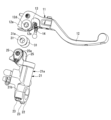
- FIG. 3 is a cross-sectional view taken along line II of FIG. 1 is a front view showing a state in which an operating lever according to a first embodiment of the present invention is attached to a hydraulic master cylinder; 1 is an exploded perspective view of an operating lever, a hydraulic master cylinder, and a wear-suppressing member according to a first embodiment of the present invention; FIG. 11 is a cross-sectional view of a main portion showing a state in which an operating lever of a second embodiment of the present invention is attached to a hydraulic master cylinder.
- FIGS 1 to 3 show a first embodiment of the present invention.
- the operating lever 11 of this embodiment operates a hydraulic master cylinder 21 connected to a brake for a motorcycle.
- a piston (not shown) of the hydraulic master cylinder is pushed through a push rod 14, and hydraulic pressure increased by the pushing of the piston is supplied to the brake.
- the hydraulic master cylinder 21 is a well-known vertically-mounted master cylinder, with a cylinder hole (not shown) equipped with a piston formed in the vertically long cylinder body 21a.
- a bracket half 21b is formed on the bottom side of the cylinder hole of the cylinder body 21a, and the hydraulic master cylinder 21 is attached to the handlebar 24 by fastening the bracket half 21b to the half-bracket 22 with bolts 23.
- a pair of operating lever support members 25, 25 are provided on the cylinder bore opening side of the cylinder body 21a, and the operating lever 11 is inserted between the operating lever support members 25, 25 via a wear suppression member 31 and is attached rotatably by a pivot 26 (shaft member).
- the operating lever support members 25, 25 are formed as a pair with a predetermined gap between them, and have first pivot insertion holes 25a, 25a (through holes of the present invention) through which the pivot 26 is inserted.
- the operating lever 11 is composed of a lever body 12 disposed on the front side of the handlebar 24, and a knocker 13 disposed between the inside of the lever body 12 and the cylinder body 21a.
- the lever body 12 has a first pivot base 12a (the pivot base of the present invention) inserted between a pair of operating lever support members 25, 25 and rotatably supported by a pivot 26, and an operating part 12b arranged approximately along the front side of the vehicle body of the handlebar 24, and a storage recess 12c for storing the knocker 13 is formed on the inside of the first pivot base 12a.
- a second pivot insertion hole 12d (a through hole of the present invention) for inserting the pivot 26 via a collar 27 is formed coaxially with the first pivot insertion holes 25a, 25a through the first pivot base 12a.
- countersunk holes 12e, 12e are formed around the opening of the second pivot insertion hole 12d on the opposing surface facing the operating lever support member 25.
- the knocker 13 is housed in the housing recess 12c, has a second rotation base 13a rotatably supported by a pivot 26, and is fitted with a push rod 14 that pushes the piston when the knocker 13 rotates.
- a third pivot insertion hole 13b (a through hole of the present invention) through which the pivot 26 passes via a collar 27 is formed in the second rotation base 13a coaxially with the first pivot insertion hole 25a and the second pivot insertion hole 12d.
- the wear-suppressing members 31 are donut-shaped disk parts made of thin resin plates, for example, and have lubricating properties.
- the wear-suppressing members 31 are each disposed in the counterbore 12e, and have an insertion hole 31a in the center through which the pivot 26 is inserted.
- the wear-suppressing members 31 also have a thickness that fills the gap between the overlapping surfaces S1, S1 ( Figure 1) of the first pivot base 12a and the operating lever support member 25 when the first pivot base 12a is inserted between the pair of operating lever support members 25, 25.
- the first rotation base 12a of the lever body 12 is inserted between the pair of operating lever support members 25, 25 and overlapped. Furthermore, the pivot 26 is inserted through the first pivot insertion hole 25a, the insertion hole 31a, and the collar 27 and fixed. As a result, the operating lever 11 is rotatably supported on the operating lever support members 25, 25 with the wear-suppressing members 31 attached between the overlapping surfaces S1, S1.
- FIG. 4 shows a second embodiment of the present invention, in which the same components as those in the first embodiment are given the same reference numerals and detailed descriptions thereof are omitted.
- one of the wear suppression members 32 has a conical portion 32b that protrudes in a conical shape toward the outer periphery from the insertion hole 32a through which the pivot 26 is inserted.
- the wear suppression member 32 keeps the first rotating base 12a in a state of always being pressed against the other operating lever support member 25, even if the thickness of the wear suppression members 31 and 32 changes due to repeated rotation of the operating lever 11, there is no risk of the operating lever 11 rattling.
- the present invention is not limited to the above-mentioned embodiments, and the structure of the hydraulic master cylinder is arbitrary.
- the operating lever is not limited to one composed of a lever body and a knocker, and may not have a knocker.
- the operating lever is not limited to one supported by a pair of operating lever support members as in the above-mentioned embodiments, but may be one supported by one operating lever support member, and only one side of the rotation base of the operating lever may overlap with the operating lever support member.
- a countersink is provided in the lever body to attach the wear-suppressing member, but a countersink can also be provided in the operating lever support member to attach the wear-suppressing member.
- the operating lever of the present invention can also be applied to an operating lever operated via a connecting means such as a hydraulic master cylinder for a clutch or a cable.
Landscapes
- Engineering & Computer Science (AREA)
- Mechanical Engineering (AREA)
- Physics & Mathematics (AREA)
- General Physics & Mathematics (AREA)
- Automation & Control Theory (AREA)
- Transportation (AREA)
- Mechanical Control Devices (AREA)
Priority Applications (1)
| Application Number | Priority Date | Filing Date | Title |
|---|---|---|---|
| JP2025559032A JPWO2025109797A1 (https=) | 2023-11-21 | 2024-07-10 |
Applications Claiming Priority (2)
| Application Number | Priority Date | Filing Date | Title |
|---|---|---|---|
| JP2023-197073 | 2023-11-21 | ||
| JP2023197073 | 2023-11-21 |
Publications (1)
| Publication Number | Publication Date |
|---|---|
| WO2025109797A1 true WO2025109797A1 (ja) | 2025-05-30 |
Family
ID=95826269
Family Applications (1)
| Application Number | Title | Priority Date | Filing Date |
|---|---|---|---|
| PCT/JP2024/024934 Pending WO2025109797A1 (ja) | 2023-11-21 | 2024-07-10 | 操作レバー |
Country Status (2)
| Country | Link |
|---|---|
| JP (1) | JPWO2025109797A1 (https=) |
| WO (1) | WO2025109797A1 (https=) |
Citations (3)
| Publication number | Priority date | Publication date | Assignee | Title |
|---|---|---|---|---|
| JPS61165893U (https=) * | 1985-04-04 | 1986-10-15 | ||
| JPH0428192U (https=) * | 1990-07-02 | 1992-03-05 | ||
| WO2008132765A1 (en) * | 2007-04-27 | 2008-11-06 | Freni Brembo S.P.A. | Collapsible control lever device |
-
2024
- 2024-07-10 WO PCT/JP2024/024934 patent/WO2025109797A1/ja active Pending
- 2024-07-10 JP JP2025559032A patent/JPWO2025109797A1/ja active Pending
Patent Citations (3)
| Publication number | Priority date | Publication date | Assignee | Title |
|---|---|---|---|---|
| JPS61165893U (https=) * | 1985-04-04 | 1986-10-15 | ||
| JPH0428192U (https=) * | 1990-07-02 | 1992-03-05 | ||
| WO2008132765A1 (en) * | 2007-04-27 | 2008-11-06 | Freni Brembo S.P.A. | Collapsible control lever device |
Also Published As
| Publication number | Publication date |
|---|---|
| JPWO2025109797A1 (https=) | 2025-05-30 |
Similar Documents
| Publication | Publication Date | Title |
|---|---|---|
| JP2009535573A (ja) | ディスクブレーキの摺動機構 | |
| US5983742A (en) | Rack and pinion steering device with split roller rack bar support | |
| US20230391419A1 (en) | Drive Unit of a Vehicle which can be Operated by Means of Muscle Power and/or Motor Power | |
| FR2626336A1 (fr) | Double volant amortisseur notamment pour vehicules automobiles | |
| JP5411600B2 (ja) | 車両用ブレーキ液圧制御装置の基体および車両用ブレーキ液圧制御装置 | |
| WO2025109797A1 (ja) | 操作レバー | |
| JP3934095B2 (ja) | ラジアルマウント型ディスクブレーキ | |
| EP1437521B1 (fr) | Dispositif de fixation d'un étrier de frein à disque sur une fusée d'essieu, notamment pour véhicule automobile | |
| US20250020177A1 (en) | Caliper brake | |
| JP5297341B2 (ja) | 車両用ディスクブレーキのキャリパボディ | |
| US20060151266A1 (en) | A Corner Assembly for a Vehicle | |
| US4056249A (en) | Engine mounting apparatus | |
| CA2588125A1 (en) | Brake disk, in particular for a utility vehicle | |
| JP2015219589A (ja) | 車両用ペダル装置の軸受部構造 | |
| JP4864341B2 (ja) | 電動アクチュエータ | |
| JP4746910B2 (ja) | 電動アクチュエータ | |
| GB2225396A (en) | Disc brake mounting structure | |
| CN221138040U (zh) | Esp执行机构的托架总成及其车辆 | |
| EP4150229B1 (fr) | Cylindre de roue amorti par rapport au plateau support, frein a tambour comprenant ledit cylindre et procede d'assemblage dudit frein a tambour | |
| CN211599349U (zh) | 一种简单型制动鼓 | |
| JP2001132783A (ja) | ディスクブレーキ | |
| JP2006311655A (ja) | 電動アクチュエータ | |
| JP4200142B2 (ja) | ディーゼルエンジンとその製造方法 | |
| JP6897422B2 (ja) | アクスルハウジング支持構造 | |
| JP2011105088A (ja) | ベアリング押さえ構造 |
Legal Events
| Date | Code | Title | Description |
|---|---|---|---|
| 121 | Ep: the epo has been informed by wipo that ep was designated in this application |
Ref document number: 24893792 Country of ref document: EP Kind code of ref document: A1 |
|
| ENP | Entry into the national phase |
Ref document number: 2025559032 Country of ref document: JP Kind code of ref document: A |