WO2025100409A1 - 透水性マット、ペット用システムトイレ及び包装体 - Google Patents
透水性マット、ペット用システムトイレ及び包装体 Download PDFInfo
- Publication number
- WO2025100409A1 WO2025100409A1 PCT/JP2024/039303 JP2024039303W WO2025100409A1 WO 2025100409 A1 WO2025100409 A1 WO 2025100409A1 JP 2024039303 W JP2024039303 W JP 2024039303W WO 2025100409 A1 WO2025100409 A1 WO 2025100409A1
- Authority
- WO
- WIPO (PCT)
- Prior art keywords
- water
- permeable mat
- absorbent sheet
- permeable
- less
- Prior art date
- Legal status (The legal status is an assumption and is not a legal conclusion. Google has not performed a legal analysis and makes no representation as to the accuracy of the status listed.)
- Pending
Links
Images






Classifications
-
- A—HUMAN NECESSITIES
- A01—AGRICULTURE; FORESTRY; ANIMAL HUSBANDRY; HUNTING; TRAPPING; FISHING
- A01K—ANIMAL HUSBANDRY; AVICULTURE; APICULTURE; PISCICULTURE; FISHING; REARING OR BREEDING ANIMALS, NOT OTHERWISE PROVIDED FOR; NEW BREEDS OF ANIMALS
- A01K1/00—Housing animals; Equipment therefor
- A01K1/01—Removal of dung or urine ; Removal of manure from stables
Definitions
- This disclosure relates to a water-permeable mat, a pet toilet system, and a packaging body.
- Patent Document 1 describes a pet system toilet that includes a tray, an absorbent sheet placed on the tray, and a cardboard panel with a corrugated honeycomb structure placed on the absorbent mat.
- a pet system toilet when a pet sits on the panel to urinate, the urine passes through the panel and is absorbed by the absorbent sheet.
- the panel on the absorbent sheet By placing the panel on the absorbent sheet, the pet does not come into direct contact with the absorbent sheet, and as a result, the urine absorbed by the absorbent sheet is prevented from flowing back up into the pet's legs.
- Patent Document 1 is made of cardboard and has a hard, uneven surface, which may not suit the preferences of some pets and they may avoid using the toilet. It is difficult to promote the use of pet toilet systems unless a comfortable excretion environment is provided for pets.
- the present disclosure therefore aims to provide a water-permeable mat that can provide a comfortable excretion environment for pets, a pet toilet system that includes the water-permeable mat, and a package that contains the water-permeable mat.
- a water-permeable mat for pets is placed on an absorbent sheet for use.
- the water-permeable mat has a porous structure, and in a dry state, a compression work (WC value) according to a KES compression test is 13 gf cm/cm2 or more and 60 gf cm/cm2 or less .
- the compression work load in the KES compression test is the work load up to the maximum pressure when the water-permeable mat is compressed in the thickness direction, and the higher this value, the softer the water-permeable mat is and the easier it is to compress.
- the compression work load of the water-permeable mat In a dry state, by setting the compression work load of the water-permeable mat to 13 gf ⁇ cm/cm2 or more , it is possible to impart cushioning that pets prefer.
- the water-permeable mat is too soft, the water-permeable mat is excessively compressed when a pet sits on it, and the pet's legs may come into contact with the absorbent sheet, and the urine absorbed by the absorbent sheet may flow back to the pet's legs.
- this water-permeable mat can provide a clean and comfortable excretion environment for pets.
- the water-permeable mat may have a compression work (WC value) in a wet state according to a KES compression test of 13 gf ⁇ cm/ cm2 or more and 60 gf ⁇ cm/ cm2 or less. In this case, even in a wet state, a clean and comfortable excretion environment can be provided for pets.
- WC value compression work
- the water-permeable mat may be made of urethane resin. By making the water-permeable mat out of urethane resin, it is possible to impart cushioning that pets prefer, and to provide a comfortable excretion environment for pets.
- the water-permeable mat may have a lightness L* of 55 or less in the L*a*b* color system when viewed in the thickness direction. Pets such as dogs tend to avoid urine marks on the absorbent sheet when urinating, and may be reluctant to urinate on the absorbent sheet after it has been used, even if the absorbent sheet is capable of absorbing the urine. By making the water-permeable mat a dark color, the visibility of urine marks on the absorbent sheet is reduced, allowing the absorbent sheet to be used repeatedly.
- the water-permeable mat may have a thickness of 2 mm or more and less than 7 mm in its natural state. By making the thickness of the water-permeable mat 2 mm or more, when a pet sits on it, the water-permeable mat compresses, causing the pet's legs to come into contact with the absorbent sheet, preventing urine from flowing back up onto the pet's legs. By making the thickness of the water-permeable mat less than 7 mm, the water-permeable mat can be made water-permeable.
- the water-permeable mat may have a thickness of 0.5 mm or more when a load of 990 g/ cm2 is applied in the thickness direction. In this case, it is possible to prevent urine from flowing back to the pet's legs due to contact with the absorbent sheet.
- the number of holes per square inch may be 8 to 20.
- the number of holes per square inch of the water-permeable mat 8 to 20 urine excreted on the water-permeable mat can pass through and be absorbed by the absorbent sheet.
- the water-permeable mat may have a tensile strength of 8 N/ mm2 or more in a wet state. In this case, even if a pet repeatedly urinates on the water-permeable mat, the water-permeable mat is less likely to be damaged, and therefore the water-permeable mat can be used for a long period of time without replacement.
- the water-permeable mat may have a tensile strength in a dry state that is 90% or more and 110% or less of its tensile strength in a wet state. In this case, the water-permeable mat is less likely to be damaged when a pet urinates on it and the mat becomes wet, making it possible to repeatedly use the water-permeable mat for a long period of time.
- the permeable mat may be provided with a hydrophilizing agent.
- a hydrophilizing agent By providing the permeable mat with a hydrophilizing agent, urine is prevented from remaining on the surface of the permeable mat. As a result, the permeable mat can be kept clean.
- the permeable mat may contain an antibacterial agent containing silver ions.
- the odor of urine is suppressed by the antibacterial agent containing silver ions, so that the permeable mat can be kept clean.
- the water-permeable mat may have an apparent density of 25 kg/m 3 or more and 35 kg/m 3 or less. By making the apparent density of the water-permeable mat within the above range, it is possible to impart appropriate water permeability to the water-permeable mat.
- the water-permeable mat may have an air permeability of 0.001 or more and 0.006 or less. By setting the air permeability of the water-permeable mat within the above range, it is possible to impart appropriate water permeability to the water-permeable mat.
- One embodiment of the pet toilet system comprises an absorbent sheet having water absorption properties, a water-permeable mat placed on the absorbent sheet, and a toilet body that holds the absorbent sheet and the water-permeable mat, the water-permeable mat having a porous structure, and in a dry state, a compression work load (WC value) according to a KES compression test of 13 gf-cm/cm2 or more and 60 gf-cm/cm2 or less.
- WC value compression work load
- the compression work (WC value) of the water-permeable mat By setting the compression work (WC value) of the water-permeable mat to 13 gf ⁇ cm/ cm2 or more and 60 gf ⁇ cm/cm2 or less in a dry state, a clean and comfortable excretion environment can be provided for pets, thereby promoting the use of the pet toilet system.
- a packaging body contains a water-permeable mat for pets that is placed on an absorbent sheet for use.
- the water-permeable mat has a porous structure, and in a dry state, a compression work (WC value) according to a KES compression test is 13 gf cm/ cm2 or more and 60 gf cm/cm2 or less , and the inner surface of the packaging body is made of a resin film.
- the inner surface of the packaging body is made of a resin film, the friction between the inner surface of the packaging body and the water-permeable mat is reduced, making it possible to easily remove the water-permeable mat from the packaging body.
- Various aspects of the present invention can provide a comfortable excretion environment for pets.
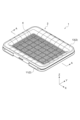
- FIG. 1 is a perspective view showing a system toilet for pets according to one embodiment.
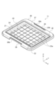
- FIG. 2 is an exploded perspective view showing main components of the pet toilet system shown in FIG. 1.
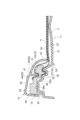
- 2 is a cross-sectional view of the pet toilet system taken along line AA in FIG. 1.
- FIG. 4 is an enlarged cross-sectional view of a portion of FIG. 3 .
- FIG. FIG. FIG. FIG. FIG. FIG. 2 is a schematic plan view of an absorbent sheet.
- 12 is a cross-sectional view taken along line BB in FIG. 11.
- FIG. 2 is an enlarged plan view showing a portion of a water-permeable mat.
- 1 is a schematic cross-sectional view showing a package containing a plurality of water-permeable mats.
- Fig. 1 is a perspective view showing a system toilet 1 according to one embodiment.
- Fig. 2 is a perspective view showing the main components of the system toilet 1 disassembled.
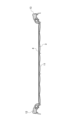
- Fig. 3 is a cross-sectional view taken along line A-A in Fig. 1.
- Fig. 4 is a cross-sectional view showing an enlarged fitting portion of the system toilet 1 shown in Fig. 3.
- the system toilet 1 shown in Figures 1 to 4 is an excretion device for pets.
- pets broadly include vertebrates and invertebrates, and typically include pet animals such as dogs, cats, rabbits, and hamsters.
- the system toilet 1 is installed indoors for pets kept indoors, and provides an excretion space.
- Pet waste is typically urine, but also includes bodily fluids such as low-viscosity feces, saliva, and blood.
- the system toilet 1 includes a toilet body 2, an absorbent sheet 3 having water-absorbing properties, and a water-permeable mat 4 placed on the absorbent sheet 3.
- the toilet body 2 holds the absorbent sheet 3 and the water-permeable mat 4.
- the stacking direction of the absorbent sheet 3 and the water-permeable mat 4 is referred to as the "vertical direction Z,” and the two directions perpendicular to the vertical direction Z are referred to as the "width direction X” and the “depth direction Y,” respectively.
- the width direction X is parallel to the longitudinal direction of the toilet body 2
- the depth direction Y is parallel to the lateral direction of the toilet body 2.
- the direction from the absorbent sheet 3 toward the water-permeable mat 4 is referred to as the "upward”
- the direction from the water-permeable mat 4 toward the absorbent sheet 3 is referred to as the "downward.”
- the toilet body 2 is a device for holding the absorbent sheet 3 and the water-permeable mat 4.
- the toilet body 2 comprises a bottom plate portion 11, a middle frame portion 12 arranged on the bottom plate portion 11, and an upper frame portion 13 arranged on the middle frame portion 12.
- the bottom plate portion 11, the middle frame portion 12, and the upper frame portion 13 are formed, for example, by molding a thermoplastic resin, and are flexible.
- the bottom plate portion 11, the middle frame portion 12, and the upper frame portion 13 are detachable from each other in the vertical direction Z.
- FIG. 5 is a perspective view of the bottom plate 11 of the toilet body 2.
- the bottom plate 11 has a substantially rectangular bottom surface 21 with the longitudinal direction being the width direction X when viewed from the vertical direction Z, and an outer edge portion 22 surrounding the bottom surface 21.
- the bottom surface 21 has an upper surface 23 on which the absorbent sheet 3 is placed.
- the upper surface 23 of the bottom surface 21 has an uneven shape.
- the upper surface 23 has a plurality of recesses 23a recessed downward and a protrusion 23b protruding upward.
- the plurality of recesses 23a are two-dimensionally arranged along the width direction X and the depth direction Y.
- Each of the plurality of recesses 23a is formed in a quadrangular shape (square shape) when viewed from the vertical direction Z.
- the protrusions 23b are formed in a lattice shape that divides the plurality of recesses 23a.
- the outer edge portion 22 is formed in a substantially rectangular frame shape when viewed from the vertical direction Z, and is arranged to surround the bottom portion 21. Typically, the outer edge portion 22 is formed integrally with the bottom portion 21 from a thermoplastic resin.
- the outer edge portion 22 has a side wall portion 24 that rises upward from the outer edge of the bottom portion 21, an inner peripheral portion 25 that extends outward from the upper end of the side wall portion 24, and an outer peripheral portion 26 that extends outward from the outer edge of the inner peripheral portion 25.
- the side wall portion 24 has a function of blocking urine excreted on the bottom portion 21 through the water-permeable mat 4 and the absorbent sheet 3.
- the side wall portion 24 may have a notch (not shown) formed therein to return urine that has entered a mating recess 27 (described later) to the bottom portion.
- the inner peripheral portion 25 is provided on the outside of the side wall portion 24, and has an upper surface 25a that is positioned above the upper surface 23 of the bottom portion 21 (see FIG. 4).
- the inner peripheral portion 25 is formed with a mating recess (first mating recess) 27 that is recessed downward from the upper surface 25a of the inner peripheral portion 25.
- the mating recess 27 is a groove that is approximately rectangular when viewed from the vertical direction Z, and is formed in the region between the side wall portion 24 and the outer peripheral portion 26.
- the bottom of the mating recess 27 is positioned above the upper surface 23 of the bottom portion 21, and below the upper surface 25a of the inner peripheral portion 25.
- the outer circumferential portion 26 is provided outside the inner circumferential portion 25 and has an upper surface 26a that is located above the upper surface 25a of the inner circumferential portion 25.
- a cutout portion 26b is formed by cutting out a part of the outer circumferential portion 26 toward the depth direction Y.
- a columnar connection portion 28 is provided in the cutout portion 26b. The connection portion 28 extends in the width direction X, and both ends are connected to the outer circumferential portion 26.
- FIG. 6 is a perspective view of the middle frame portion 12, and FIG. 7 is a bottom view of the middle frame portion 12.
- the middle frame portion 12 has a generally rectangular frame shape when viewed from the up-down direction Z, and is detachably attached to the outer edge portion 22 of the bottom plate portion 11.
- the middle frame portion 12 has an inner periphery portion 31 and an outer periphery portion 32 arranged outside the inner periphery portion 31.
- the inner periphery portion 31 of the middle frame portion 12 is positioned above the inner periphery portion 25 of the bottom plate portion 11, and the outer periphery portion 32 of the middle frame portion 12 is positioned above the outer periphery portion 26 of the bottom plate portion 11.
- the inner periphery 31 has an engagement protrusion (first engagement protrusion) 33 and an engagement recess (second engagement recess) 34.
- the engagement protrusion 33 is formed along the inner edge of the middle frame portion 12 and has a generally rectangular shape when viewed from below.
- the engagement protrusion 33 protrudes downward (towards the bottom plate portion 11) from the lower surface of the middle frame portion 12.
- the engagement protrusion 33 is disposed in a position facing the engagement recess 27 of the bottom surface portion 21 and can be engaged with the engagement recess 27.
- the engagement recess 27 and the engagement protrusion 33 constitute the lower engagement structure 10 that connects the bottom plate portion 11 and the middle frame portion 12.
- the mating recess 34 is recessed downward from the upper surface of the inner circumferential portion 31.
- the mating recess 34 is a groove having a substantially rectangular shape, and is disposed outside the mating protrusion 33 when viewed from the vertical direction Z.
- the depth of the mating recess 34 (the distance from the upper surface of the inner circumferential portion 31 to the bottom of the mating recess 34 in the vertical direction Z) may be deeper than the depth of the mating recess 27 (the distance from the upper surface 25a of the inner circumferential portion 25 to the bottom of the mating recess 27 in the vertical direction Z).
- One or more openings 37 may be formed in the bottom of the fitting recess 34 (see FIG. 7).
- the multiple openings 37 are through holes that penetrate the middle frame 12 in the thickness direction (vertical direction Z), and allow urine that has entered the fitting recess 34 to be discharged to the bottom surface 21.
- the outer peripheral portion 32 of the middle frame portion 12 has an outer peripheral protrusion 35.
- the outer peripheral protrusion 35 is formed along the outer edge of the middle frame portion 12.
- the outer peripheral protrusion 35 has a generally rectangular shape when viewed from below, and protrudes downward (toward the bottom plate portion 11) from the outer edge of the middle frame portion 12. As shown in FIG. 4, the tip of the outer peripheral protrusion 35 is positioned above the tip of the fitting protrusion 33 and below the bottom of the fitting recess 34. When the fitting protrusion 33 of the middle frame portion 12 is fitted into the fitting recess 27 of the bottom plate portion 11, the outer peripheral protrusion 35 is supported on the outer peripheral portion 26 of the bottom plate portion 11.
- the middle frame portion 12 has a pair of first middle frame sides 12A extending in the width direction X and a pair of second middle frame sides 12B extending in the depth direction Y. As shown in FIG. 6, the length of the pair of first middle frame sides 12A in the width direction X is longer than the length of the pair of second middle frame sides 12B in the depth direction Y. The width w2 in the width direction X of the pair of second middle frame sides 12B may be smaller than the width w1 in the depth direction Y of the pair of first middle frame sides 12A.
- the pair of first middle frame sides 12A have latches (second locking structures) 38 for locking the middle frame portion 12 to the bottom plate portion 11.
- the latches 38 include a latch body 38a extending downward from the outer edges of the pair of first middle frame sides 12A, and an extension portion 38b that is disposed inside the latch body 38a in the depth direction Y and faces the latch body 38a via a gap 38s (see FIG. 7).
- the latch body 38a has a first claw portion 38c and a second claw portion 38d.
- the first claw portion 38c protrudes inward in the depth direction Y from the inner surface of the latch body 38a.
- the second claw portion 38d protrudes outward in the depth direction Y from the outer surface of the latch body 38a.
- FIG. 8 is a perspective view of the upper frame portion 13, and FIG. 9 is a bottom view of the upper frame portion 13.
- the upper frame portion 13 has a generally rectangular frame shape when viewed from the vertical direction Z, and is detachably attached to the middle frame portion 12.
- the upper frame portion 13 has an inner periphery 41 and an outer periphery 42 arranged outside the inner periphery 41. When the upper frame portion 13 is attached to the middle frame portion 12, the inner periphery 41 of the upper frame portion 13 is positioned above the inner periphery 31 of the middle frame portion 12, and the outer periphery 42 of the upper frame portion 13 is positioned above the outer periphery 32 of the middle frame portion 12.
- the inner peripheral portion 41 of the upper frame portion 13 has an inner peripheral convex portion 43 and a mating convex portion (second mating convex portion) 44 (see FIG. 4).
- the inner peripheral convex portion 43 is formed along the inner edge of the upper frame portion 13 and has a generally rectangular shape when viewed from below.
- the inner peripheral convex portion 43 protrudes downward from the inner edge of the upper frame portion 13 toward the bottom plate portion 11.
- the mating protrusion 44 has a generally rectangular shape when viewed from below, and is disposed outside the inner peripheral protrusion 43.
- the mating protrusion 44 is disposed at a position facing the mating recess 34 of the middle frame portion 12, and protrudes downward from the lower surface of the upper frame portion 13 toward the mating recess 34.
- the mating protrusion 44 can be fitted into the mating recess 34.
- the lower end of the inner peripheral protrusion 43 is positioned lower than the lower end of the mating protrusion 44.
- the maximum length of the mating protrusion 44 of the upper frame 13 may be longer than the maximum length of the mating protrusion 33.
- the outer periphery 42 of the upper frame portion 13 has an outer periphery protrusion 45.
- the outer periphery protrusion 45 is formed along the outer edge of the upper frame portion 13.
- the outer periphery protrusion 45 has a generally rectangular shape when viewed from below, and protrudes downward from the outer edge of the upper frame portion 13 towards the middle frame portion 12. As shown in FIG. 4, when the upper frame portion 13 is attached to the middle frame portion 12 and the mating protrusion 44 is mated with the mating recess 34, the outer periphery protrusion 45 of the upper frame portion 13 is supported on the outer periphery protrusion 35 of the middle frame portion 12.
- the upper frame portion 13 has a pair of first upper frame sides 13A extending in the width direction X and a pair of second upper frame sides 13B extending in the depth direction Y.
- the length of the pair of first upper frame sides 13A in the width direction X is longer than the length of the pair of second upper frame sides 13B in the depth direction Y.
- the width w4 in the width direction X of the pair of second upper frame sides 13B may be smaller than the width w3 in the depth direction Y of the pair of first upper frame sides 13A.
- the pair of first upper frame sides 13A has latches (first locking structures) 46 for locking the upper frame portion 13 to the middle frame portion 12.
- the latches 46 extend downward from the outer edge of the first upper frame side 13A.
- the latches 46 have openings 46a that penetrate the latches 46 in the thickness direction (depth direction Y).
- depth direction Y thickness direction
- the latches 46 slide along the outer surface of the latches 38 while elastically deforming so as to spread outward in the depth direction Y, and the second claw portions 38d of the latches 38 fit into the openings 46a of the latches 46.
- Figure 10 is a side view showing the toilet body 2 in which the latches 46 of the upper frame portion 13 fit into the latches 38 of the middle frame portion 12, connecting the bottom plate portion 11, the middle frame portion 12, and the upper frame portion 13.
- the upper frame portion 13 has an upper surface 47 that slopes downward (closer to the bottom plate portion 11) from the outer edge to the inner edge of the upper frame portion 13.
- the upper surface 47 is a curved surface whose angle of inclination increases as it approaches the inner edge of the upper frame portion 13. Because the upper surface 47 is inclined as described above, when a pet's urine falls on the upper frame portion 13, the urine can fall along the upper surface 47 onto the bottom plate portion 21.
- the upper surface 47 of the upper frame portion 13 may have an uneven shape.
- a pair of first upper frame sides 13A of the upper frame portion 13 has a plurality of raised portions (convex portions) 48 extending in the depth direction Y arranged at equal intervals along the width direction X.
- a pair of second upper frame sides 13B of the upper frame portion 13 has a plurality of raised portions 48 arranged at equal intervals along the depth direction Y.
- an inclined surface (concave portion) 49 that allows urine to flow toward the absorbent sheet 3 is formed.
- the upper surface 47 of the pair of first upper frame sides 13A has raised portions 48 and inclined surfaces 49 arranged alternately in the width direction X
- the upper surface 47 of the pair of second upper frame sides 13B has raised portions 48 and inclined surfaces 49 arranged alternately in the depth direction Y.
- the inclined surfaces 49 are curved so as to approach downward as they move away from the adjacent raised portions 48. That is, since the center of the inclined surface 49 in the width direction X or depth direction Y is the lowest, urine on the upper frame portion 13 is collected at the center of the inclined surface 49 and guided to the bottom surface portion 21.
- the toilet body 2 holds an absorbent sheet 3 and a water-permeable mat 4.
- the absorbent sheet 3 is a thin, water-absorbent sheet that is placed on the bottom surface 21 of the bottom plate 11 and absorbs pet urine.
- the absorbent sheet 3 has a roughly rectangular planar shape and dimensions that correspond to the dimensions of the toilet body 2.
- the absorbent sheet 3 has a length of 400 mm to 600 mm in the longitudinal direction and a width of 300 mm to 500 mm in the lateral direction.
- the absorbent sheet 3 is placed and held between the bottom plate 11 and the middle frame 12 of the toilet body 2.
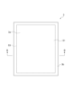
- FIG. 11 is a schematic plan view of the absorbent sheet 3.
- FIG. 12 is a cross-sectional view taken along line B-B in FIG. 11.
- the absorbent sheet 3 includes a top sheet 51 arranged on the top side of the absorbent sheet 3, a back sheet 52 arranged on the back side of the absorbent sheet 3, and an absorbent 53 arranged between the top sheet 51 and the back sheet 52.
- the top sheet 51 is liquid permeable and is formed in a substantially rectangular shape.
- the top sheet 51 is made of a resin film having a large number of openings 51a penetrating the top sheet 51 in the thickness direction. Typically, polyethylene or polypropylene is used as the material for the resin film.
- the top sheet 51 may be made of a laminate in which a nonwoven fabric is bonded to a resin film, or a water-repellent nonwoven fabric. Pet urine discharged on the absorbent sheet 3 passes through the openings 51a formed in the top sheet 51 and moves to the absorbent 53 side.
- the back sheet 52 is water-impermeable and is formed in a roughly rectangular shape with substantially the same dimensions as the top sheet 51.
- materials for the back sheet 52 include a resin film such as polyethylene or polypropylene, a laminate in which a nonwoven fabric is bonded to the resin film, or a water-repellent nonwoven fabric.
- the absorbent 53 is disposed between the top sheet 51 and the back sheet 52, and absorbs urine that has passed through the top sheet 51.
- the absorbent 53 has a substantially rectangular planar shape, is slightly smaller than the top sheet 51 and the back sheet 52, and is disposed in the center of the absorbent sheet 3. Therefore, as shown in FIG. 11, the absorbent sheet 3 has an absorbent section 3a in which the absorbent 53 is disposed between the top sheet 51 and the back sheet 52, and a flap section 3b in which the absorbent 53 is not disposed between the top sheet 51 and the back sheet 52.
- the absorbent section 3a is a substantially rectangular area disposed in the center of the absorbent 53 when viewed from the thickness direction, and is partially joined to the top sheet 51 by the hot melt adhesive HM.
- the flap section 3b is a rectangular frame-shaped area in which the top sheet 51 and the back sheet 52 are bonded together without the absorbent, and is formed to surround the absorbent section 3a. That is, the flap section 3b is formed along the outer edge of the absorbent sheet 3.
- the top sheet 51 and the back sheet 52 are directly bonded together by hot melt adhesive HM without the absorbent body 53 in between.
- the absorbent body 53 includes an absorbent core 54 containing pulp and a superabsorbent polymer (SAP: Superabsorbent Polymer), and a core wrap 55 covering the surface of the absorbent core.
- the pulp used for the absorbent core 54 may be, for example, chemical pulp, cellulose fiber, rayon, acetate, or other cellulose fiber.
- the SAP used may be, for example, a starch-based, acrylic acid-based, or amino acid-based particulate or fibrous polymer.
- the core wrap 55 is wrapped around the absorbent core 54 so as to cover at least a portion of the surface of the absorbent core 54.
- the absorbent sheet 3 may further include a cover sheet 56.
- the cover sheet 56 is disposed between the top sheet 51 and the absorbent core 54, and covers the surface of the absorbent core 54.
- the cover sheet 56 has a generally rectangular planar shape, and has substantially the same dimensions as the absorbent body 53 when viewed in the thickness direction.
- the cover sheet 56 is made of, for example, tissue or nonwoven fabric, and is liquid permeable.
- the absorbent sheet 3 is disposed between the bottom plate 11 and the middle frame 12 of the toilet body 2.
- the flap portion 3b of the absorbent sheet 3 is sandwiched between the mating recess 27 and the mating protrusion 33, and is held between the bottom plate 11 and the middle frame 12.
- the absorbent body 53 is prevented from breaking and the SAP from leaking from the absorbent sheet 3.
- the water-permeable mat 4 is a thin sheet that has a porous structure and is water-permeable.
- the water-permeable mat 4 is held between the middle frame 12 and the upper frame 13 of the toilet body 2, and is placed on the absorbent sheet 3 when in use.
- the water-permeable mat 4 has the function of preventing urine from flowing back through the absorbent sheet 3 while allowing pet urine to pass through.
- the water-permeable mat 4 is made of a foamed resin with an open cell structure, such as a urethane resin. Since urethane resin has high water resistance, by making the water-permeable mat 4 out of a urethane resin, it is possible to use the water-permeable mat 4 repeatedly without replacing it. For example, an ether-based urethane resin with high tensile strength is used as the urethane resin.
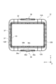
- FIG. 13 is an enlarged plan view of a portion of the water-permeable mat 4 according to one embodiment.
- the water-permeable mat 4 has a large number of holes 4a formed therein, penetrating the water-permeable mat 4 in the thickness direction.
- the water-permeable mat 4 may have 8 to 20 holes 4a formed per square inch when viewed in the thickness direction. By setting the number of holes 4a per square inch to 8 to 20, the water-permeable mat 4 can maintain its rigidity while ensuring its liquid permeability.
- the opening shape of the holes 4a may be any planar shape, such as a circle, an ellipse, or a polygon.
- the water-permeable mat 4 is placed on the absorbent sheet 3 when in use.
- the water-permeable mat 4 may be placed away from the absorbent sheet 3.
- a pet using the system toilet 1 sits on the water-permeable mat 4 to urinate.
- the pet's urine passes through the holes 4a formed in the water-permeable mat 4 and moves to the absorbent sheet 3 side, where it is absorbed by the absorbent body 53 of the absorbent sheet 3.
- the water-permeable mat 4 prevents the pet's legs from coming into contact with the absorbent sheet 3, preventing the urine absorbed by the absorbent sheet 3 from flowing back up to the pet's legs.
- the compression work (WC value) of the water-permeable mat 4 in a dry state according to a KES compression test is set to 13 gf ⁇ cm/ cm2 or more and 60 gf ⁇ cm/ cm2 or less.
- the compression work according to the KES compression test is the work required to apply maximum pressure when the water-permeable mat 4 is compressed in the thickness direction, and the higher this value, the softer the water-permeable mat 4 is and the easier it is to compress.
- the compression work can be measured, for example, using a Kato Tech KES-G5 handy compression tester.
- a test piece of the water-permeable mat 4 of 5 cm x 10 cm is attached to a test stand, and the test piece is compressed in the thickness direction between steel plates having a circular plane of an area of 2 cm 2.
- the compression speed is 20 ⁇ m/sec, and the maximum compression load is 4.9 kPa.
- the load P on the test piece, the thickness Tm of the test piece at a load of 4.9 kPa (50 gf/cm 2 ), and the thickness T0 at a load of 49 Pa (0.5 gf/cm 2 ) are measured, and the compression work WC of the water-permeable mat 4 is calculated based on the following formula (1).
- the water-permeable mat 4 may have a compression work load of 13 gf ⁇ cm/ cm2 or more and 60 gf ⁇ cm/ cm2 or less in a wet state according to a KES compression test.
- the wet state refers to a state in which the water-permeable mat 4 is immersed in water for 5 minutes and then the water on the surface of the water-permeable mat 4 is wiped off with a cloth.
- the tensile strength of the water-permeable mat 4 in the wet state may be 8 N/ mm2 or more.
- a test piece of 25 mm x 150 mm is cut out from the water-permeable mat 4, and both ends of the test piece are pulled at a speed of 100 mm/min using an autograph testing device, and the force [N] at which the test piece is torn can be taken as the tensile strength of the water-permeable mat 4.
- the tensile strength of the water-permeable mat 4 in the dry state may be 90% or more and 110% or less of the tensile strength in the wet state.
- the water-permeable mat 4 has a generally rectangular planar shape and dimensions that correspond to the dimensions of the toilet body 2.
- the water-permeable mat 4 has a length of 400 mm to 600 mm in the longitudinal direction and a width of 300 mm to 500 mm in the lateral direction.
- the thickness of the water-permeable mat 4 is 2 mm or more and less than 7 mm in a natural state.
- the water-permeable mat 4 is compressed, which prevents the pet's legs from coming into contact with the absorbent sheet 3 and causing urine to flow back to the pet's legs.
- the permeability of the water-permeable mat 4 can be ensured.
- the water-permeable mat 4 may have a thickness and rigidity such that the thickness is 0.5 mm or more when a load of 990 g/ cm2 is applied from the thickness direction.
- the water-permeable mat 4 may have an apparent density of 25 kg/m 3 or more and 35 kg/m 3 or less.
- the apparent density means the mass per unit volume including the volume of a large number of voids 4a. The higher the ratio of the volume of the voids 4a to the volume of the water-permeable mat 4, the lower the apparent density.
- the apparent density of the water-permeable mat 4 25 kg/m 3 or more, the rigidity of the water-permeable mat 4 can be increased, and the water-permeable mat 4 can be compressed and the pet's legs can be prevented from contacting the absorbent sheet 3.
- the apparent density of the water-permeable mat 4 25 kg/m 3 or more, the water permeability of the water-permeable mat 4 can be ensured.
- the water-permeable mat 4 may have an air permeability of 0.001 or more and 0.006 or less.
- the airflow resistance is measured, for example, by cutting a test piece of a specified size from the water-permeable mat 4 and using a Kato Tech Co., Ltd. air permeability tester (KES-F8) or an equivalent air permeability tester. For example, air is released and sucked through the test piece at a constant flow rate, and the integral value of the pressure loss measured using a semiconductor differential pressure gauge is taken as the airflow resistance. The airflow resistance is then measured multiple times (for example, five times), and the average value is taken as the airflow resistance of the water-permeable mat 4.
- KES-F8 air permeability tester
- the permeable mat 4 may be coated with a hydrophilizing agent such as a surfactant and subjected to a hydrophilization treatment. By subjecting the permeable mat 4 to a hydrophilization treatment, it is possible to suppress urine remaining on the permeable mat 4.
- the permeable mat 4 may also contain an antibacterial agent containing silver ions. The antibacterial agent can suppress the urine odor remaining on the permeable mat 4. By suppressing the urine odor with the hydrophilic agent and antibacterial agent, it becomes possible to use the permeable mat 4 for a long period of time, and the number of times the permeable mat 4 needs to be replaced can be reduced.
- the water-permeable mat 4 is colored in a color different from that of the top sheet 51.
- the water-permeable mat 4 is colored in a dark color tone such as gray or black in order to reduce the visibility of urine stains on the absorbent sheet 3.
- the lightness L* of the water-permeable mat 4 in the L*a*b* color system may be 55 or less when it is overlaid on a standard white board and viewed in the thickness direction.
- the procedure for attaching the absorbent sheet 3 and the water-permeable mat 4 to the toilet body 2 will be described.
- the latches 38 of the middle frame portion 12 are pushed outward in the width direction X by hand to release the engagement between the latches 38 and the connection portions 28 of the bottom plate portion 11.
- the middle frame portion 12 is lifted and removed from the bottom plate portion 11.
- the absorbent sheet 3 is placed on the bottom plate portion 11 so that the flap portions 3b of the absorbent sheet 3 are positioned on the outer edge portion 22 of the bottom plate portion 11.
- the mating protrusions 33 of the middle frame portion 12 are mated with the mating recesses 27 of the bottom plate portion 11, and the middle frame portion 12 is attached to the bottom plate portion 11.
- the flap portions 3b of the absorbent sheet 3 are sandwiched between the mating recesses 27 and the mating protrusions 33. At this time, the absorbent sheet 3 is pressed against the mating protrusion 33 while deeply inserted into the mating recess 27, so a strong frictional force acts on the absorbent sheet 3, and the absorbent sheet 3 is held firmly in place.
- the latches 46 of the upper frame portion 13 are pushed outward in the width direction X to release the engagement between the latches 46 and the latches 38 of the middle frame portion 12.
- the upper frame portion 13 is then lifted up and removed from the middle frame portion 12.
- the water-permeable mat 4 is placed on the middle frame portion 12, and the mating protrusions 44 of the upper frame portion 13 are fitted into the mating recesses 34 of the middle frame portion 12 to attach the upper frame portion 13 to the middle frame portion 12.
- the outer edge of the water-permeable mat 4 is sandwiched between the mating recesses 34 and the mating protrusions 44.
- the water-permeable mat 4 is pressed against the mating protrusions 44 while deeply inserted into the mating recesses 34, so that a strong frictional force acts on the water-permeable mat 4, and the water-permeable mat 4 is held firmly in place.
- the maximum length of the mating protrusion 44 is longer than the maximum length of the mating protrusion 33, the retention force of the water-permeable mat 4 by the upper mating structure 20 is greater than the retention force of the absorbent sheet 3 by the lower mating structure 10.
- the water-permeable mat 4 is also pressed downward by the inner circumferential protrusion 43. As a result, frictional force acts between the water-permeable mat 4 and the inner circumferential protrusion 43, further increasing the holding power of the water-permeable mat 4.
- the system toilet 1 When the absorbent sheet 3 and water-permeable mat 4 are attached to the toilet body 2, the system toilet 1 is ready for use.
- a pet steps over the relatively narrow second upper frame side 13B onto the water-permeable mat 4 and urinates.
- the pet's urine passes through the water-permeable mat 4 and is absorbed by the absorbent sheet 3.
- the pet steps over the second upper frame side 13B and gets off the system toilet 1.
- the absorbent sheet 3 has a high water retention capacity and can be used multiple times.
- the absorbent sheet 3 can absorb a pet's urine for three days.
- the water-permeable mat 4 is placed on the absorbent sheet 3, so that even if the absorbent sheet 3 is used repeatedly, the urine absorbed by the absorbent sheet 3 is prevented from flowing back up the pet's legs.
- the water-permeable mat 4 has a brightness L* of 55 or less, the visibility of urine stains on the absorbent sheet 3 is reduced when the water-permeable mat 4 is placed on the absorbent sheet 3, and it is prevented that the pet dislikes urine stains and avoids using the toilet. Therefore, the frequency of replacing the absorbent sheet 3 can be reduced.
- the procedure for replacing the absorbent sheet 3 will be described.
- the latches 38 of the middle frame portion 12 are pushed outward in the width direction X by hand to disengage the latches 38 from the connection portions 28 of the bottom plate portion 11.
- the middle frame portion 12 is then lifted up and removed from the bottom plate portion 11.
- the used absorbent sheet 3 is then replaced with a new absorbent sheet 3, and the middle frame portion 12 is then reattached to the bottom plate portion 11. In this way, the user can replace the absorbent sheet 3 without directly touching the water-permeable mat 4. Therefore, the absorbent sheet 3 can be replaced without getting hands dirty.
- the water-permeable mat 4 can be removed and replaced individually from the system toilet 1 by removing the upper frame 13 from the middle frame 12 in the reverse order to that used when installing the water-permeable mat 4.
- the water-permeable mat 4 has a compression work (WC value) set to 13 gf ⁇ cm/cm2 or more and 60 gf ⁇ cm/cm2 or less, so it can provide the cushioning that pets prefer, while preventing urine absorbed by the absorbent sheet 3 from flowing back up into the pet's legs when the pet's legs come into contact with the absorbent sheet 3. Therefore, this water-permeable mat 4 can provide a clean and comfortable excretion environment for pets.
- WC value compression work
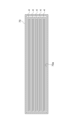
- FIG. 14 is a schematic cross-sectional view showing a packaging body 70 that stores a plurality of water-permeable mats 4.
- the water-permeable mat 4 is, for example, a bag having a substantially rectangular parallelepiped shape, and is made of, for example, synthetic resin, paper, or a combination of these.
- An opening line (not shown) is formed in the packaging body 70, and opening the packaging body 70 along the opening line forms an opening for removing the water-permeable mat 4 stored in the packaging body 70.
- the water-permeable mat 4 is folded in three and stored in a stacked state inside the packaging body 70.
- the water-permeable mat 4 is removed from the packaging body 70 by inserting a finger into the packaging body 70 through the opening of the packaging body 70, grasping the water-permeable mat 4, and pulling it out.
- the inner surface 70a of the packaging body 70 is made of a resin film such as polyethylene, polypropylene, or polyethylene terephthalate.
- a resin film such as polyethylene, polypropylene, or polyethylene terephthalate.
- a mating recess 27 is formed in the bottom plate 11 and a mating protrusion 33 is formed in the middle frame 12, but an engaging protrusion may be formed in the bottom plate 11 and a mating recess may be formed in the middle frame 12, and the middle frame 12 may be connected to the bottom plate 11 by these engaging protrusions and mating recesses engaging with each other.
- a mating recess 34 is formed in the middle frame 12 and a mating protrusion 44 is formed in the upper frame 13, but an engaging protrusion is formed in the middle frame 12 and a mating recess is formed in the upper frame 13, and the upper frame 13 may be connected to the middle frame 12 by these engaging protrusions and mating recesses engaging with each other.
- the mating recess 27, the mating protrusion 33, the mating recess 34, and the mating protrusion 44 are formed in a rectangular shape when viewed from the vertical direction Z, but the shapes of the mating recess 27, the mating protrusion 33, the mating recess 34, and the mating protrusion 44 are not limited to a rectangular shape.
- the mating protrusion 33 and the mating protrusion 44 may be cylindrical pins, and the mating recess 27 and the mating recess 34 may be holes having a circular planar shape that fits into these pins.
- fitting recesses 27, fitting protrusions 33, fitting recesses 34, and fitting protrusions 44 may be arranged in multiple locations along the periphery of the bottom plate portion 11, middle frame portion 12, and upper frame portion 13, and the fitting protrusions 33 and fitting protrusions 44 may be fitted into the fitting recesses 27 and fitting recesses 34, respectively, thereby attaching the middle frame portion 12 to the bottom plate portion 11 and attaching the upper frame portion 13 to the middle frame portion 12.
- the length in the width direction X of the pair of first middle frame sides 12A is longer than the length in the depth direction Y of the pair of second middle frame sides 12B, but the length in the width direction X of the pair of first middle frame sides 12A may be shorter than the length in the depth direction Y of the pair of second middle frame sides 12B.
- the material of the water-permeable mat 4 is not limited to urethane resin having an open-cell structure.
- the water-permeable mat 4 can be made of any material as long as it has a porous structure with a compression work of 13 gf cm/cm2 or more and 60 gf cm/cm2 or less .
- This disclosure includes the following:
- a water-permeable mat for pets that is placed on an absorbent sheet and used A water-permeable mat having a porous structure, in which the compression work (WC value) in a dry state according to a KES compression test is 13 gf ⁇ cm/ cm2 or more and 60 gf ⁇ cm/cm2 or less .
- [4] A water-permeable mat described in any one of [1] to [3], which has a lightness L* of 55 or less in the L*a*b* color system when viewed in the thickness direction.
- [7] A water-permeable mat described in any one of [1] to [6], in which the number of holes per square inch is 8 to 20 when viewed in the thickness direction.
- a package for housing a water-permeable mat for pets that is used by being placed on an absorbent sheet comprising:
- the water-permeable mat has a porous structure, and in a dry state, a compression work (WC value) according to a KES compression test is 13 gf cm/ cm2 or more and 60 gf cm/cm2 or less ;
- a packaging body the inner surface of which is made of a resin film.
Landscapes
- Life Sciences & Earth Sciences (AREA)
- Environmental Sciences (AREA)
- Zoology (AREA)
- Animal Husbandry (AREA)
- Biodiversity & Conservation Biology (AREA)
- Housing For Livestock And Birds (AREA)
Abstract
一態様のペット用の透水性マットは、吸収性シート上に配置して使用される。この透水性マットは、多孔質構造を有し、乾燥状態において、KES圧縮試験による圧縮仕事量(WC値)が13gf・cm/cm2以上、60gf・cm/cm2以下である。
Description
本開示は、透水性マット、ペット用システムトイレ及び包装体に関する。
犬や猫等のペットの排泄物を処理するペット用システムトイレが知られている。例えば、特許文献1には、受け皿と、当該受け皿上に配置された吸収性シートと、吸収性マット上に配置されたコルゲートハニカム構造を有する段ボール製のパネルとを備えるペット用システムトイレが記載されている。このペット用システムトイレでは、ペットがパネルの上に乗って排尿すると、尿はパネルを通過して吸収性シートに吸収される。吸収性シート上にパネルを配置することにより、ペットが吸収性シートに直接接触しなくなり、その結果、吸収性シートに吸収された尿がペットの脚に逆戻りすることが防止される。
多くの飼い主は、部屋を清潔に保つために、ペットが室内に設置したトイレで排泄することを望むが、ペットにトイレでの排泄を慣れさせることは容易なことではない。一般的にペットは、清潔で快適な環境で排泄することを好み、ペットの好みに合わないトイレを用意してもペットはトイレの使用を嫌がることが多い。例えば、特許文献1に記載のパネルは、段ボール製であり、その表面が硬くて凸凹しているため、ペットによっては好みに合わず、トイレの使用を忌避することがある。ペットにとって快適な排泄環境を提供しなければ、ペット用システムトイレの利用を促進することは難しい。
そこで本開示は、ペットにとって快適な排泄環境を提供することができる透水性マット、当該透水性マットを含むペット用システムトイレ、及び、当該透水性マットを収容する包装体を提供することを目的とする。
一態様のペット用の透水性マットは、吸収性シート上に配置して使用される。この透水性マットは、多孔質構造を有し、乾燥状態において、KES圧縮試験による圧縮仕事量(WC値)が13gf・cm/cm2以上、60gf・cm/cm2以下である。
KES圧縮試験による圧縮仕事量は、透水性マットを厚み方向に圧縮したときの最大圧力までの仕事量であり、この値が高いほど透水性マットが柔らかく、圧縮されやすいことを示す。乾燥状態において、透水性マットの圧縮仕事量を13gf・cm/cm2以上にすることにより、ペットの好むクッション性を付与することができる。一方で、透水性マットが余りに柔らかいと、ペットが乗ったときに透水性マットが過剰に圧縮され、ペットの脚が吸収性シートに接触し、吸収性シートに吸収された尿がペットの脚に逆戻りする恐れがある。これに対し、透水性マットの圧縮仕事量を60gf・cm/cm2以下にすることにより、ペットの脚の汚染を防止することができる。したがって、この透水性マットによれば、ペットにとって清潔で快適な排泄環境を提供することができる。
透水性マットは、湿潤状態において、KES圧縮試験による圧縮仕事量(WC値)が、13gf・cm/cm2以上、60gf・cm/cm2以下であってもよい。この場合には、湿潤状態の場合でも、ペットにとって清潔で快適な排泄環境を提供することができる。
透水性マットはウレタン樹脂によって構成されていてもよい。透水性マットがウレタン樹脂によって構成されることにより、ペットの好むクッション性を付与することができ、ペットにとって快適な排泄環境を提供することができる。
透水性マットは、厚み方向から見た場合に、L*a*b*表色系における明度L*が55以下であってもよい。犬等のペットは、吸収性シート上の尿跡を避けて排泄する傾向があるため、吸収性シートで尿を吸収できる場合であっても、使用した吸収性シートに排泄することを嫌がることがある。透水性マットを暗い色にすることにより、吸収性シート上の尿跡の視認性が低下するため、吸収性シートを繰り返し使用させることができる。
透水性マットは、自然状態で2mm以上7mm未満の厚みを有していてもよい。透水性マットの厚みを2mm以上にすることにより、ペットが乗ったときに透水性マットの圧縮により、ペットの脚が吸収性シートに接触して尿がペットの脚に逆戻りすることが抑制される。透水性マットの厚みを7mm未満にすることにより、透水性マットに透水性を付与することができる。
透水性マットは、厚み方向から990g/cm2の荷重を加えたときの厚みが0.5mm以上であってもよい。この場合には、ペットの脚が吸収性シートに接触して尿がペットの脚に逆戻りすることを抑制することができる。
透水性マットの厚み方向から見て、1平方インチ当たりの空孔の数が8個以上20個以下であってもよい。透水性マットの1平方インチ当たりの空孔の数を8個以上20個以下にすることにより、透水性マット上に排泄された尿を透過して、吸収性シートに吸収させることができる。
透水性マットは、湿潤状態における引張強度が8N/mm2以上であってもよい。この場合には、ペットが透水性マット上で繰り返し排尿をした場合であっても、透水性マットが破損しにくくなるため、透水性マットを長期間交換せずに使用することが可能となる。
透水性マットは、湿潤状態における引張強度に対して、乾燥状態における引張強度が90%以上110%以下であってもよい。この場合には、ペットが透水性マット上で排尿して当該透水性マットが濡れたときに透水性マットが破損しにくくなるため、透水性マットを長期間にわたって繰り返し使用することが可能となる。
透水性マットには、親水化剤が付与されていてもよい。透水性マットに親水化剤を付与することにより、透水性マットの表面に尿が残留することが抑制される。その結果、透水性マットを清潔に保つことができる。
透水性マットは、銀イオンを含有する抗菌剤を含んでいてもよい。この場合には、銀イオンを含有する抗菌剤によって尿の臭気が抑制されるので、透水性マットを清潔に保つことができる。
透水性マットは、25kg/m3以上、35kg/m3以下の見かけ密度を有していてもよい。透水性マットの見かけ密度を上記範囲にすることにより、透水性マットに適切な透水性を付与することができる。
透水性マットは、0.001以上、0.006以下の通気度を有していてもよい。透水性マットの通気度を上記範囲にすることにより、透水性マットに適切な透水性を付与することができる。
一態様のペット用システムトイレは、吸水性を有する吸収性シートと、吸収性シート上に配置される透水性マットと、吸収性シート及び透水性マットを保持するトイレ本体と、を備え、透水性マットは、多孔質構造を有し、乾燥状態において、KES圧縮試験による圧縮仕事量(WC値)が、13gf・cm/cm2以上、60gf・cm/cm2以下である。
乾燥状態において、透水性マットの圧縮仕事量(WC値)を13gf・cm/cm2以上、60gf・cm/cm2以下にすることにより、ペットにとって清潔で快適な排泄環境を提供することができる。その結果、ペット用システムトイレの利用を促進することができる。
一態様に係る包装体は、吸収性シート上に配置して使用されるペット用の透水性マットを収容する。透水性マットは、多孔質構造を有し、乾燥状態において、KES圧縮試験による圧縮仕事量(WC値)が、13gf・cm/cm2以上、60gf・cm/cm2以下であり、包装体の内面が樹脂フィルムによって構成されている。
包装体の内面が樹脂フィルムによって構成されることにより、当該包装体の内面と透水性マットとの摩擦力が小さくなり、透水性マットを包装体から容易に取り出すことが可能となる。
本発明の種々の態様によれば、ペットにとって快適な排泄環境を提供することができる。
以下、図面を参照しながら本開示の実施形態が詳細に説明される。図面の説明において同一要素には同一符号が付され、重複する説明は省略される。図面は、理解の容易化のために一部を簡略化又は誇張して描いている場合があり、寸法比率は図面に記載のものに限定されない。
以下、一実施形態に係るペット用の透水性マットを含むペット用システムトイレ(以下、「システムトイレ」という。)について説明する。図1は、一実施形態に係るシステムトイレ1を示す斜視図である。図2は、システムトイレ1の主要部品を分解して示す斜視図である。図3は、図1のA-A線に沿った断面図である。図4は、図3に示すシステムトイレ1の嵌合部を拡大して示す断面図である。
図1~図4に示すシステムトイレ1は、ペット用の排泄装置である。本明細書において、ペットは、脊椎動物や無脊椎動物を広く包含し、典型的には、犬、猫、ウサギ、ハムスターなどの愛玩動物を含む。典型的には、システムトイレ1は、室内で飼育するペットのために室内に設置され、排泄スペースを提供する。ペットの排泄物は、典型的には尿であるが、排泄物には低粘度の糞、唾液、血液等の体液が含まれる。
図1に示すように、システムトイレ1は、トイレ本体2と、吸水性を有する吸収性シート3と、吸収性シート3上に配置される透水性マット4とを備えている。トイレ本体2は、吸収性シート3及び透水性マット4を保持する。
なお、以下の説明では、吸収性シート3及び透水性マット4の積層方向を「上下方向Z」といい、上下方向Zに垂直な二方向をそれぞれ「幅方向X」及び「奥行方向Y」というものとする。図1に示す実施形態では、幅方向Xは、トイレ本体2の長手方向に平行な方向であり、奥行方向Yは、トイレ本体2の短手方向に平行な方向である。また、吸収性シート3から透水性マット4に向かう方向を「上方」といい、透水性マット4から吸収性シート3へ向かう方向を「下方」というものとする。
トイレ本体2は、吸収性シート3及び透水性マット4を保持するための装置である。図2に示すように、トイレ本体2は、底板部11と、底板部11上に配置される中枠部12と、中枠部12上に配置される上枠部13とを備えている。底板部11、中枠部12及び上枠部13は、例えば熱可塑性樹脂を成形することにより形成され、可撓性を有する。後述するように、底板部11、中枠部12及び上枠部13は、上下方向Zに互いに脱着可能である。
図5は、トイレ本体2の底板部11の斜視図である。図5に示すように、底板部11は、上下方向Zから見て、幅方向Xを長手方向とする略矩形状の底面部21と、当該底面部21を囲む外縁部22とを有している。底面部21は、吸収性シート3を載置するための上面23を有する。底面部21の上面23は、凹凸形状を有している。具体的には、上面23は、下方に窪む複数の凹部23aと、上方に隆起する凸部23bを有している。複数の凹部23aは、幅方向X及び奥行方向Yに沿って二次元状に配列されている。複数の凹部23a各々は、上下方向Zから見て四角形状(正方形状)に形成されている。凸部23bは、複数の凹部23aを区画する格子状に形成されている。
外縁部22は、上下方向Zから見て略矩形枠状に形成され、底面部21を囲むように配置されている。典型的には、外縁部22は、熱可塑性樹脂により底面部21と一体的に形成されている。外縁部22は、底面部21の外縁から上方に立ち上げられた側壁部24と、当該側壁部24の上端から外側に延出した内周部25と、当該内周部25の外縁から外側に延出した外周部26とを備えている。側壁部24は、透水性マット4及び吸収性シート3を介して底面部21上に排泄された尿を堰き止める機能を有する。側壁部24には、後述する嵌合凹部27に進入した尿を底面部に戻すための切り欠き(不図示)が形成されていてもよい。
内周部25は、側壁部24の外側に設けられ、底面部21の上面23よりも上方に配置された上面25aを有している(図4参照)。内周部25には、当該内周部25の上面25aから下方に窪む嵌合凹部(第1嵌合凹部)27が形成されている。嵌合凹部27は、上下方向Zから見て略矩形状の溝であり、側壁部24と外周部26との間の領域に形成されている。嵌合凹部27の底部は、底面部21の上面23よりも上方に配置され、内周部25の上面25aよりも下方に配置されている。
外周部26は、内周部25の外側に設けられ、内周部25の上面25aよりも上方に配置された上面26aを有している。外周部26の奥行方向Yの一対の端部には、当該外周部26の一部が奥行方向Yに向けて切り欠かれた切欠部26bが形成されている。当該切欠部26bには、柱状の接続部28が設けられている。接続部28は、幅方向Xに延在し、その両端が外周部26に連結されている。
図6は中枠部12の斜視図であり、図7は中枠部12の下面図である。中枠部12は、上下方向Zから見て略矩形枠状を有し、底板部11の外縁部22上に着脱自在に取り付けられる。中枠部12は、内周部31と、当該内周部31の外側に配置された外周部32とを備えている。中枠部12が底板部11に取り付けられたときに、中枠部12の内周部31は、底板部11の内周部25の上方に配置され、中枠部12の外周部32は、底板部11の外周部26の上方に配置される。
図4及び図6に示すように、内周部31は、嵌合凸部(第1嵌合凸部)33及び嵌合凹部(第2嵌合凹部)34を有している。嵌合凸部33は、中枠部12の内縁に沿って形成され、下方から見て略矩形状を呈している。嵌合凸部33は、中枠部12の下面から下方(底板部11側)に向けて突出している。嵌合凸部33は、底面部21の嵌合凹部27に対向する位置に配置され、嵌合凹部27に嵌合可能である。嵌合凸部33が嵌合凹部27に嵌合されると、底板部11と中枠部12とが連結され、水平方向(幅方向X及び奥行方向Y)における底板部11及び中枠部12のずれが抑制される。嵌合凹部27及び嵌合凸部33は、底板部11と中枠部12とを連結する下部嵌合構造10を構成する。
嵌合凹部34は、内周部31の上面から下方に窪んでいる。嵌合凹部34は、略矩形状の溝であり、上下方向Zから見て、嵌合凸部33の外側に配置されている。上下方向Zから見て、嵌合凹部34の深さ(上下方向Zにおける内周部31の上面から嵌合凹部34の底部までの距離)は、嵌合凹部27の深さ(上下方向Zにおける内周部25の上面25aから嵌合凹部27の底部までの距離)よりも深くてもよい。
嵌合凹部34の底部には、1又は複数の開口37が形成されていてもよい(図7参照)。複数の開口37は、中枠部12を厚み方向(上下方向Z)に貫通する貫通孔であり、嵌合凹部34に進入した尿を底面部21に排出する。
中枠部12の外周部32は、外周凸部35を有している。外周凸部35は、中枠部12の外縁に沿って形成されている。外周凸部35は、下方から見て略矩形状を有し、中枠部12の外縁から下方(底板部11側)に向けて突出している。図4に示すように、外周凸部35の先端は、嵌合凸部33の先端よりも上方に配置され、嵌合凹部34の底部よりも下方に配置されている。中枠部12の嵌合凸部33が底板部11の嵌合凹部27に嵌合されたときに、外周凸部35は、底板部11の外周部26上に支持される。
中枠部12は、幅方向Xに延在する一対の第1中枠辺12Aと、奥行方向Yに延在する一対の第2中枠辺12Bを有している。図6に示すように、幅方向Xにおける一対の第1中枠辺12Aの長さは、奥行方向Yにおける一対の第2中枠辺12Bの長さよりも長い。一対の第2中枠辺12Bの幅方向Xの幅w2は、一対の第1中枠辺12Aの奥行方向Yの幅w1よりも小さくてもよい。
一対の第1中枠辺12Aは、中枠部12を底板部11に係止するためのラッチ(第2係止構造)38を有している。ラッチ38は、一対の第1中枠辺12Aの外縁から下方に延在するラッチ本体38aと、奥行方向Yにおけるラッチ本体38aの内側に配置され、空隙38sを介してラッチ本体38aに対面する延出部38bとを含んでいる(図7参照)。
ラッチ本体38aは、第1爪部38c及び第2爪部38dを有している。第1爪部38cは、ラッチ本体38aの内面から奥行方向Yの内方に突出している。第2爪部38dは、ラッチ本体38aの外面から奥行方向Yの外方に突出している。底板部11上に中枠部12を取り付けると、底板部11の接続部28が空隙38sに収容されると共に、ラッチ本体38aの弾性変形によって、第1爪部38cが接続部28に係止される。これにより、中枠部12が底板部11に固定される。
図8は上枠部13の斜視図であり、図9は上枠部13の下面図である。上枠部13は、上下方向Zから見て略矩形枠状を有し、中枠部12上に着脱自在に取り付けられる。上枠部13は、内周部41と、当該内周部41の外側に配置された外周部42とを備えている。上枠部13が中枠部12上に取り付けられたときに、上枠部13の内周部41は、中枠部12の内周部31の上方に配置され、上枠部13の外周部42は、中枠部12の外周部32の上方に配置される。
上枠部13の内周部41は、内周凸部43及び嵌合凸部(第2嵌合凸部)44を有している(図4参照)。内周凸部43は、上枠部13の内縁に沿って形成され、下方から見て略矩形状を呈している。内周凸部43は、上枠部13の内縁から底板部11側に向けて下方に突出している。
嵌合凸部44は、下方から見て略矩形状を有し、内周凸部43の外側に配置されている。嵌合凸部44は、中枠部12の嵌合凹部34に対向する位置に配置され、上枠部13の下面から嵌合凹部34に向けて下方に突出している。嵌合凸部44は、嵌合凹部34に嵌合可能である。嵌合凸部44が嵌合凹部34に嵌合されると、中枠部12と上枠部13とが連結され、水平方向(幅方向X及び奥行方向Y)における中枠部12と上枠部13とのずれが抑制される。嵌合凹部34及び嵌合凸部44は、中枠部12と上枠部13を連結する上部嵌合構造20を構成する。
図4に示すように、嵌合凹部34と嵌合凸部44とが嵌合しているときに、内周凸部43の下端は、嵌合凸部44の下端よりも下方に配置されている。また、上枠部13の嵌合凸部44の最大長さは、嵌合凸部33の最大長さよりも長くてもよい。
上枠部13の外周部42は、外周凸部45を有している。外周凸部45は、上枠部13の外縁に沿って形成されている。外周凸部45は、下方から見て略矩形状を有し、上枠部13の外縁から中枠部12に向けて下方に突出している。図4に示すように、上枠部13が中枠部12に取り付けられ、嵌合凸部44が嵌合凹部34に嵌合されたときに、上枠部13の外周凸部45は、中枠部12の外周凸部35上に支持される。
図8に示すように、上枠部13は、幅方向Xに延在する一対の第1上枠辺13Aと、奥行方向Yに延在する一対の第2上枠辺13Bを有している。幅方向Xにおける一対の第1上枠辺13Aの長さは、奥行方向Yにおける一対の第2上枠辺13Bの長さよりも長い。一対の第2上枠辺13Bの幅方向Xの幅w4は、一対の第1上枠辺13Aの奥行方向Yの幅w3よりも小さくてもよい。
一対の第1上枠辺13Aは、上枠部13を中枠部12に係止するためのラッチ(第1係止構造)46を有している。ラッチ46は、第1上枠辺13Aの外縁から下方に延在している。ラッチ46には、当該ラッチ46を厚み方向(奥行方向Y)に貫通する開口46aが形成されている。上枠部13を中枠部12に取り付ける際には、ラッチ46が奥行方向Yの外側に広がるように弾性変形しながらラッチ38の外面に沿ってスライドされ、ラッチ38の第2爪部38dがラッチ46の開口46aに嵌合する。これにより、上枠部13が中枠部12に固定される。図10は、上枠部13のラッチ46が中枠部12のラッチ38と嵌合して、底板部11、中枠部12及び上枠部13が連結されたトイレ本体2を示す側面図である。
図8に示すように、上枠部13は、当該上枠部13の外縁から内縁に向かうにつれて下方に向かうように(底板部11に近づくように)傾斜する上面47を有している。上面47は、上枠部13の内縁に近づくにつれてその傾斜角が大きくなるような湾曲面である。上面47が上記のように傾斜していることにより、ペットの尿が上枠部13にかかったときに、上面47に沿って尿を底面部21に落下させることができる。
一実施形態では、上枠部13の上面47は、凹凸形状を有していてもよい。例えば、上枠部13の一対の第1上枠辺13Aには、奥行方向Yに延在する複数の隆起部(凸部)48が幅方向Xに沿って等間隔で配列されている。同様に、上枠部13の一対の第2上枠辺13Bには、複数の隆起部48が奥行方向Yに沿って等間隔で配列されている。複数の隆起部48の間には、尿を吸収性シート3に向けて流す傾斜面(凹部)49が形成されている。すなわち、一対の第1上枠辺13Aの上面47は、幅方向Xに隆起部48及び傾斜面49が交互に配列され、一対の第2上枠辺13Bの上面47は、奥行方向Yに隆起部48及び傾斜面49が交互に配列されている。傾斜面49は、隣接する隆起部48から離れるにつれて下方に近づくように湾曲している。すなわち、傾斜面49の幅方向X又は奥行方向Yの中心において最も低くなっているので、上枠部13上の尿は傾斜面49の中心に集められ、底面部21に案内される。
トイレ本体2は、吸収性シート3及び透水性マット4を保持している。吸収性シート3は、吸水性を有する薄型のシートであり、底板部11の底面部21上に配置され、ペットの尿を吸収する。吸収性シート3は、略矩形状の平面形状を有し、トイレ本体2の寸法に応じた寸法を有している。例えば、吸収性シート3は、長手方向において400mm~600mmの長さを有し、短手方向において300mm~500mmの幅を有している。吸収性シート3は、トイレ本体2の底板部11と中枠部12との間に配置され、保持される。
図11は、吸収性シート3の概略的な平面図である。図12は、図11のB-B線に沿った断面図である。図11及び図12に示すように、吸収性シート3は、当該吸収性シート3の表面側に配置された表面シート51と、当該吸収性シート3の裏面側に配置された裏面シート52と、表面シート51と裏面シート52との間に配置された吸収体53とを備えている。表面シート51は、液透過性を有し、略矩形状に形成されている。表面シート51は、当該表面シート51を厚み方向に貫通する多数の開孔51aを有する樹脂フィルムによって構成されている。典型的には、樹脂フィルムの材料としては、ポリエチレン又はポリプロピレンが用いられる。なお、表面シート51は、樹脂フィルムに不織布を貼り合わせた積層体、又は、撥水性の不織布によって構成されていてもよい。吸収性シート3に排泄されたペットの尿は、表面シート51に形成された開孔51aを通って吸収体53側に移動する。
裏面シート52は、非透水性を有し、表面シート51と実質的に同じ寸法の略矩形状に形成されている。裏面シート52の材料としては、ポリエチレン又はポリプロピレン等の樹脂フィルム、当該樹脂フィルムに不織布を貼り合わせた積層体、又は、撥水性の不織布が例示される。吸収性シート3の裏面側に液不透過性を有する裏面シート52を配置することにより、吸収性シート3上に排泄された尿が裏面側に漏れることが防止される。
吸収体53は、表面シート51と裏面シート52との間に配置され、表面シート51を通過した尿を吸収する。吸収体53は、略矩形状の平面形状を有し、表面シート51及び裏面シート52よりも一回り小さな寸法を有し、吸収性シート3の中央に配置されている。したがって、図11に示すように、吸収性シート3には、表面シート51と裏面シート52との間に吸収体53が配置された吸収部3aと、表面シート51と裏面シート52との間に吸収体53が配置されないフラップ部3bとが形成される。吸収部3aは、厚み方向から見て、吸収体53の中央に配置された略矩形状の領域であり、ホットメルト接着剤HMによって部分的に表面シート51に接合されている。フラップ部3bは、吸収体を介さずに表面シート51と裏面シート52とが貼り合わされた矩形枠状の領域であり、吸収部3aを囲むように形成されている。すなわち、フラップ部3bは、吸収性シート3の外縁に沿って形成されている。典型的には、図12に示すように、フラップ部3bでは、吸収体53を介さずに表面シート51と裏面シート52とがホットメルト接着剤HMによって直接接合されている。
吸収体53は、パルプ及び吸水性ポリマー(SAP:Superabsorbent Polymer)を含む吸収性コア54と、当該吸収性コアの表面を覆うコアラップ55とを含む。吸収性コア54のパルプとしては、例えば、化学パルプ、セルロース繊維、レーヨン、アセテート等のセルロース繊維が利用される。SAPとしては、例えばデンプン系、アクリル酸系、アミノ酸系の粒子状又は繊維状のポリマーが利用される。コアラップ55は、吸収性コア54の表面の少なくとも一部を覆うように吸収性コア54に巻き付けられている。
吸収性シート3は、カバーシート56を更に備えていてもよい。カバーシート56は、表面シート51と吸収性コア54との間に配置され、吸収性コア54の表面を覆っている。カバーシート56は、略矩形状の平面形状を有し、厚さ方向から見て吸収体53と実質的に同じ寸法を有している。カバーシート56は、例えばティッシュ又は不織布によって構成され、液透過性を有する。
吸収性シート3は、トイレ本体2の底板部11と中枠部12との間に配置される。吸収性シート3を介して底板部11と中枠部12とが連結されると、図4に示すように、吸収性シート3のフラップ部3bが、嵌合凹部27と嵌合凸部33との間で挟持され、底板部11と中枠部12と間で保持される。吸収性シート3のフラップ部3bが挟持されることにより、吸収体53が破れ、吸収性シート3からSAPが漏出することが防止される。
透水性マット4は、多孔質構造を有し、透水性を有する薄型のシートである。透水性マット4は、トイレ本体2の中枠部12と上枠部13との間で保持され、吸収性シート3上に配置して使用される。透水性マット4は、ペットの尿を透過しつつ、吸収性シート3からの尿の逆戻りを防止する機能を有する。透水性マット4は、連続気泡構造(オープンセル構造)を有する発泡樹脂、例えばウレタン樹脂によって構成されている。ウレタン樹脂は、高い耐水性を有するため、透水性マット4をウレタン樹脂によって構成することにより、透水性マット4を交換せずに繰り返し使用することが可能となる。例えば、ウレタン樹脂としては、高い引張強度を有するエーテル系のウレタン樹脂が用いられる。
図13は、一実施形態に係る透水性マット4の一部分を拡大して示す平面図である。図13に示すように、透水性マット4には、当該透水性マット4を厚さ方向に貫通する多数の空孔4aが形成されている。透水性マット4には、厚み方向から見て、1平方インチ当たりに8個以上20個以下の空孔4aが形成されていてもよい。1平方インチ当たりの空孔4aの数を8個以上20個以下にすることにより、透水性マット4の剛性を保ちつつ、透液性を確保することができる。なお、空孔4aの開口形状は、円形、楕円形又は多角形等、任意の平面形状を有し得る。
図2に示すように、透水性マット4は、吸収性シート3上に配置され、使用される。なお、透水性マット4に荷重がかかっていない場合には、透水性マット4は吸収性シート3から離間して配置されていてもよい。システムトイレ1を使用するペットは、透水性マット4の上に乗って排尿する。ペットの尿は、透水性マット4に形成された空孔4aを通って吸収性シート3側に移動し、吸収性シート3の吸収体53に吸収される。このとき、透水性マット4によって、ペットの脚が吸収性シート3に接触しないため、吸収性シート3に吸収された尿がペットの脚に逆戻りすることが防止される。
一般的に、犬等のペットは、適度なクッション性を有する環境で排泄することを好むため、透水性マット4の剛性が高すぎると、ペットによっては好みに合わず、トイレの使用を忌避することがある。そこで、透水性マット4は、乾燥状態において、KES圧縮試験による圧縮仕事量(WC値)が、13gf・cm/cm2以上、60gf・cm/cm2以下に設定されている。KES圧縮試験による圧縮仕事量は、透水性マット4を厚み方向に圧縮したときの最大圧力までの仕事量であり、この値が高いほど透水性マット4が柔らかく、圧縮されやすいことを示す。
圧縮仕事量は、例えばカトーテック社KES-G5ハンディー圧縮試験機を用いて測定することができる。圧縮仕事量を測定する際には、例えば5cm×10cmの透水性マット4の試験片を試験台に取り付け、その試験片を面積2cm2の円形平面を持つ鋼板間で厚さ方向から圧縮する。圧縮速度は20μm/secとし、圧縮最大荷重は4.9kPaとする。そして、試験片に対する荷重P、4.9kPa(50gf/cm2)荷重時の試験片の厚みTm、及び、49Pa(0.5gf/cm2)荷重時の厚みの厚みT0を測定し、下記式(1)に基づいて、透水性マット4の圧縮仕事量WCを求める。

乾燥状態において、透水性マット4の圧縮仕事量を13gf・cm/cm2以上にすることにより、ペットの好むクッション性を付与することができる。一方で、透水性マットが余りに柔らかいと、ペットが乗ったときに透水性マット4が過剰に圧縮され、ペットの脚が吸収性シート3に接触し、吸収性シート3に吸収された尿がペットの脚に逆戻りする恐れがある。これに対し、透水性マット4の圧縮仕事量を60gf・cm/cm2以下にすることにより、ペットの脚の汚染を防止することができる。
透水性マット4は、湿潤状態においても、KES圧縮試験による圧縮仕事量が、13gf・cm/cm2以上、60gf・cm/cm2以下であってもよい。湿潤状態とは、透水性マット4を水に5分間浸漬した後に、透水性マット4の表面の水を布で拭き取った状態をいう。
また、湿潤状態における透水性マット4の引張強度は、8N/mm2以上であってもよい。例えば、透水性マット4から25mm×150mmの試験片を切り出し、オートグラフ試験装置を用いて試験片の両端を100mm/minの速度で引っ張り、当該試験片が引き裂かれたときの力[N]を透水性マット4の引張強度とすることができる。乾燥状態における透水性マット4の引張強度は、湿潤状態における引張強度に対して90%以上110%以下であってもよい。透水性マット4の引張強度を8N/mm2以上にすることにより、透水性マット4上でペットが動いたときに透水性マット4が破損することを抑制することができる。
透水性マット4は、略矩形状の平面形状を有し、トイレ本体2の寸法に応じた寸法を有している。例えば、透水性マット4は、長手方向において400mm~600mmの長さを有し、短手方向において300mm~500mmの幅を有している。
また、透水性マット4の厚さは、自然状態で2mm以上7mm未満である。透水性マット4の厚みを2mm以上にすることにより、ペットが乗ったときに透水性マット4の圧縮により、ペットの脚が吸収性シート3に接触して尿がペットの脚に逆戻りすることが抑制される。透水性マット4の厚みを7mm未満にすることにより、透水性マット4の透水性を確保することができる。また、ペットの脚に尿が逆戻りすることを抑制するために、透水性マット4は、厚み方向から990g/cm2の荷重を加えたときに、厚みが0.5mm以上になるような、厚み及び剛性を有していてもよい。
また、透水性マット4は、25kg/m3以上、35kg/m3以下の見かけ密度を有していてもよい。見かけ密度は、多数の空孔4aの体積を含めた単位体積当たりの質量を意味する。透水性マット4の体積に占める空孔4aの体積の割合が高いほど、見かけ密度は低下する。透水性マット4の見かけ密度を25kg/m3以上にすることにより、透水性マット4の剛性を高めることができ、透水性マット4が圧縮され、ペットの脚が吸収性シート3に接触することを抑制することができる。一方、透水性マット4の見かけ密度を25kg/m3以上にすることにより、透水性マット4の透水性を確保することができる。
透水性マット4は、0.001以上、0.006以下の通気度を有していてもよい。通気度は、例えば下記式から計算される。
通気度(CC/cm2/sec)=12.5/通気抵抗値
通気度(CC/cm2/sec)=12.5/通気抵抗値
通気抵抗値は、例えば透水性マット4から所定の寸法の試験片を切り出し、カトーテック社製の通気性試験機(KES-F8)又はそれと同等の通気性試験機を用いて当該試験片の通気抵抗値を測定する。例えば、一定の流量で試験片を通して空気を放出及び吸引し、半導体差圧ゲージを用いて測定された圧力損失の積分値を通気抵抗値とする。そして、通気抵抗値の測定を複数回(例えば5回)繰り返し、その平均値を透水性マット4の通気抵抗値とする。
透水性マット4には、界面活性剤等の親水化剤が塗布され、親水化処理が施されてもよい。透水性マット4が親水化処理されることにより、透水性マット4への尿の残留を抑制することができる。また、透水性マット4は、銀イオンを含有する抗菌剤を含んでいてもよい。抗菌剤により、透水性マット4に残留する尿の臭いを抑制することができる。親水剤及び抗菌剤により、尿の臭いを抑制することにより、透水性マット4を長期間使用することが可能になり、透水性マット4の交換回数を低減することができる。
透水性マット4は、表面シート51とは異なる色で着色されている。例えば、透水性マット4は、吸収性シート3の尿痕の視認性を低下するために、灰色又は黒といった暗い色調で着色されている。具体的には、透水性マット4は、標準白板上に重ねて厚み方向から見た場合に、L*a*b*表色系における明度L*が55以下であってもよい。
次に、吸収性シート3及び透水性マット4をトイレ本体2に取り付ける手順について説明する。まず、中枠部12のラッチ38を手で幅方向Xの外側に押し広げてラッチ38と底板部11の接続部28との係合を解除する。そして、中枠部12を持ち上げて、中枠部12を底板部11から取り外す。次に、底板部11の外縁部22上に吸収性シート3のフラップ部3bが配置されるように、底板部11上に吸収性シート3を載置する。次に、中枠部12の嵌合凸部33を底板部11の嵌合凹部27に嵌合させ、中枠部12を底板部11に取り付ける。これにより、吸収性シート3のフラップ部3bが、嵌合凹部27と嵌合凸部33との間で挟持される。このとき、吸収性シート3は、嵌合凹部27に深く入り込んだ状態で嵌合凸部33に押圧されるため、吸収性シート3に強い摩擦力が働き、吸収性シート3が強固に保持される。
次に、上枠部13のラッチ46を幅方向Xの外側に押し広げて当該ラッチ46と中枠部12のラッチ38との係合を解除する。そして、上枠部13を持ち上げて、上枠部13を中枠部12から取り外す。次に、中枠部12上に透水性マット4を載置してから、上枠部13の嵌合凸部44を中枠部12の嵌合凹部34に嵌合させて上枠部13を中枠部12に取り付ける。これにより、透水性マット4の外縁部は、嵌合凹部34と嵌合凸部44との間で挟持される。このとき、透水性マット4は、嵌合凹部34に深く入り込んだ状態で嵌合凸部44に押圧されるので、透水性マット4に強い摩擦力が働き、透水性マット4が強固に保持される。特に、嵌合凸部44の最大長さは、嵌合凸部33の最大長さよりも長いので、上部嵌合構造20による透水性マット4の保持力は、下部嵌合構造10による吸収性シート3の保持力よりも大きくなる。
また、透水性マット4は、内周凸部43によって下方に押さえつけられる。その結果、透水性マット4と内周凸部43との間に摩擦力が作用し、透水性マット4の保持力が更に高められる。
吸収性シート3及び透水性マット4がトイレ本体2に取り付けられると、システムトイレ1が使用可能になる。システムトイレ1を使用する際には、ペットは、相対的に幅の狭い第2上枠辺13Bを跨いで透水性マット4の上に乗り、排尿する。ペットの尿は、透水性マット4を通過し、吸収性シート3に吸収される。排尿を済ませたペットは、第2上枠辺13Bを跨いでシステムトイレ1から降りる。
吸収性シート3は、高い保水力を持っているので、複数回使用することができる。例えば、吸収性シート3は、3日間分のペットの尿を吸収可能である。ここで、吸収性シート3上に透水性マット4が配置されているので、繰り返し使用した場合であっても、吸収性シート3に吸収された尿がペットに脚に逆戻りすることが防止される。また、透水性マット4が55以下の明度L*を有しているので、吸収性シート3上に透水性マット4が配置されたときに吸収性シート3の尿痕の視認性が低下し、ペットが尿痕を嫌がってトイレの使用を忌避することが防止される。したがって、吸収性シート3の交換頻度を低下させることができる。
次に、吸収性シート3の交換手順について説明する。ペットが複数回排尿して、吸収性シート3を交換する場合には、中枠部12のラッチ38を手で幅方向Xの外側に押し広げて当該ラッチ38と底板部11の接続部28との係合を解除する。そして、中枠部12を持ち上げて、中枠部12を底板部11から取り外す。次に、使用済みの吸収性シート3を新たな吸収性シート3に交換してから中枠部12を底板部11に再び取り付ける。このように、使用者は、透水性マット4に直接触れずに吸収性シート3を交換することができる。したがって、手を汚さずに、吸収性シート3を交換することができる。
透水性マット4を交換する場合にも、透水性マット4の取り付け時と反対の手順で上枠部13を中枠部12から取り外すことにより、透水性マット4をシステムトイレ1から個別に取り外して交換することができる。
以上説明したように、透水性マット4は、圧縮仕事量(WC値)が、13gf・cm/cm2以上、60gf・cm/cm2以下に設定されているので、ペットの好むクッション性を付与しつつ、ペットの脚が吸収性シート3に接触して吸収性シート3に吸収された尿がペットの脚に逆戻りすることを防止することができる。したがって、この透水性マット4によれば、ペットにとって清潔で快適な排泄環境を提供することができる。
上述した透水性マット4は、折り畳まれ、包装体70内に収容される。図14は、複数の透水性マット4を収容する包装体70を示す概略的な断面図である。透水性マット4は、例えば、略直方体形状を有する袋体であり、例えば、合成樹脂、紙、又は、これらの組み合わせによって構成される。包装体70には、不図示の開封線が形成され、当該開封線に沿って包装体70を開封することにより、包装体70に収容された透水性マット4を取り出すための開口部が形成される。
図14に示すように、透水性マット4は、三つ折りにされ、互いに重ねられた状態で包装体70内に収容される。透水性マット4を使用する場合には、包装体70の開口部から包装体70内に指を入れ、透水性マット4を摘まんで引き抜くことによって包装体70から透水性マット4を取り出す。
ここで、包装体70の内面70aは、ポリエチレン、ポリプロピレン又はポリエチレンテレフタレート等の樹脂フィルムによって構成されている。包装体70の内面70aが樹脂フィルムによって構成されることにより、内面70aと透水性マット4との摩擦力が小さくなり、透水性マット4を包装体70から容易に取り出すことが可能となる。
以上、種々の実施形態に係る透水性マット4及びシステムトイレ1について説明してきたが、本発明は上述した実施形態に限定されることなく発明の要旨を変更しない範囲で種々の変形態様を構成可能である。すなわち、上述した実施形態は例示説明を目的とするものであり、本発明の範囲を制限するものではないことに留意すべきである。
例えば、上述したトイレ本体2では、底板部11に嵌合凹部27が形成され、中枠部12に嵌合凸部33が形成されているが、底板部11に係合凸部が形成され、中枠部12に嵌合凹部が形成され、これら係合凸部及び嵌合凹部が嵌合することにより、中枠部12が底板部11に連結されてもよい。同様に、上述したトイレ本体2では、中枠部12に嵌合凹部34が形成され、上枠部13に嵌合凸部44が形成されているが、中枠部12に係合凸部が形成され、上枠部13に嵌合凹部が形成され、これら係合凸部及び嵌合凹部が嵌合することにより、上枠部13が中枠部12に連結されてもよい。
また、上述したトイレ本体2では、嵌合凹部27、嵌合凸部33、嵌合凹部34、及び、嵌合凸部44が、上下方向Zから見て矩形状に形成されているが、嵌合凹部27、嵌合凸部33、嵌合凹部34、及び、嵌合凸部44の形状は矩形状に限定されない。例えば、嵌合凸部33及び嵌合凸部44は、円柱形のピンであり、嵌合凹部27及び嵌合凹部34は、これらのピンに嵌合する円形の平面形状を有する穴であってもよい。これら嵌合凹部27、嵌合凸部33、嵌合凹部34、及び、嵌合凸部44が底板部11、中枠部12及び上枠部13の周縁に沿って複数配置され、嵌合凸部33及び嵌合凸部44が嵌合凹部27及び嵌合凹部34にそれぞれ嵌合することにより、中枠部12が底板部11に取り付けられると共に、上枠部13が中枠部12に取り付けられてもよい。
上述したトイレ本体2では、一対の第1中枠辺12Aの幅方向Xの長さが、一対の第2中枠辺12Bの奥行方向Yの長さよりも長くなっているが、一対の第1中枠辺12Aの幅方向Xの長さは、一対の第2中枠辺12Bの奥行方向Yの長さよりも短くてもよい。
透水性マット4の材料は、連続気泡構造を有するウレタン樹脂に限定されない。透水性マット4は、圧縮仕事量が13gf・cm/cm2以上、60gf・cm/cm2以下である多孔質構造を有する材料であれば、任意の材料によって構成することができる。
本開示は以下の内容を含む。
[1] 吸収性シート上に配置して使用されるペット用の透水性マットであり、
多孔質構造を有し、乾燥状態において、KES圧縮試験による圧縮仕事量(WC値)が、13gf・cm/cm2以上、60gf・cm/cm2以下である、透水性マット。
多孔質構造を有し、乾燥状態において、KES圧縮試験による圧縮仕事量(WC値)が、13gf・cm/cm2以上、60gf・cm/cm2以下である、透水性マット。
[2] 湿潤状態において、KES圧縮試験による圧縮仕事量(WC値)が、13gf・cm/cm2以上、60gf・cm/cm2以下である、[1]に記載の透水性マット。
[3] ウレタン樹脂によって構成された、[1]又は[2]に記載の透水性マット。
[4] 厚み方向から見た場合に、L*a*b*表色系における明度L*が55以下である、[1]~[3]の何れか一項に記載の透水性マット。
[5]
自然状態で2mm以上7mm未満の厚みを有する、[1]~[4]の何れか一項に記載の透水性マット。
自然状態で2mm以上7mm未満の厚みを有する、[1]~[4]の何れか一項に記載の透水性マット。
[6] 厚み方向から990g/cm2の荷重を加えたときの厚みが0.5mm以上である、[1]~[5]の何れか一項に記載の透水性マット。
[7] 厚み方向から見て、1平方インチ当たりの空孔の数が8個以上20個以下である、[1]~[6]の何れか一項に記載の透水性マット。
[8] 湿潤状態における引張強度が8N/mm2以上である、[1]~[7]の何れか一項に記載の透水性マット。
[9] 湿潤状態における引張強度に対して、乾燥状態における引張強度が90%以上110%以下である、[8]に記載の透水性マット。
[10] 親水化剤が付与されている、[1]~[9]の何れか一項に記載の透水性マット。
[11] 銀イオンを含有する抗菌剤を含む、[1]~[10]の何れか一項に記載の透水性マット。
[12] 25kg/m3以上、35kg/m3以下の見かけ密度を有する、[1]~[11]の何れか一項に記載の透水性マット。
[13] 0.001以上、0.006以下の通気度を有する、[1]~[12]の何れか一項に記載の透水性マット。
[14] 吸水性を有する吸収性シートと、
前記吸収性シート上に配置される透水性マットと、
前記吸収性シート及び前記透水性マットを保持するトイレ本体と、
を備え、
前記透水性マットは、多孔質構造を有し、乾燥状態において、KES圧縮試験による圧縮仕事量(WC値)が、13gf・cm/cm2以上、60gf・cm/cm2以下である、ペット用システムトイレ。
前記吸収性シート上に配置される透水性マットと、
前記吸収性シート及び前記透水性マットを保持するトイレ本体と、
を備え、
前記透水性マットは、多孔質構造を有し、乾燥状態において、KES圧縮試験による圧縮仕事量(WC値)が、13gf・cm/cm2以上、60gf・cm/cm2以下である、ペット用システムトイレ。
[15] 吸収性シート上に配置して使用されるペット用の透水性マットを収容する包装体であって、
前記透水性マットは、多孔質構造を有し、乾燥状態において、KES圧縮試験による圧縮仕事量(WC値)が、13gf・cm/cm2以上、60gf・cm/cm2以下であり、
その内面が樹脂フィルムによって構成されている、包装体。
前記透水性マットは、多孔質構造を有し、乾燥状態において、KES圧縮試験による圧縮仕事量(WC値)が、13gf・cm/cm2以上、60gf・cm/cm2以下であり、
その内面が樹脂フィルムによって構成されている、包装体。
1…ペット用システムトイレ、3…吸収性シート、4…透水性マット、4a…空孔、70…包装体、70a…内面。
Claims (15)
- 吸収性シート上に配置して使用されるペット用の透水性マットであり、
多孔質構造を有し、乾燥状態において、KES圧縮試験による圧縮仕事量(WC値)が、13gf・cm/cm2以上、60gf・cm/cm2以下である、透水性マット。 - 湿潤状態において、KES圧縮試験による圧縮仕事量(WC値)が、13gf・cm/cm2以上、60gf・cm/cm2以下である、請求項1に記載の透水性マット。
- ウレタン樹脂によって構成された、請求項1に記載の透水性マット。
- 厚み方向から見た場合に、L*a*b*表色系における明度L*が55以下である、請求項3に記載の透水性マット。
- 自然状態で2mm以上7mm未満の厚みを有する、請求項1に記載の透水性マット。
- 厚み方向から990g/cm2の荷重を加えたときの厚みが0.5mm以上である、請求項5に記載の透水性マット。
- 厚み方向から見て、1平方インチ当たりの空孔の数が8個以上20個以下である、請求項1に記載の透水性マット。
- 湿潤状態における引張強度が8N/mm2以上である、請求項1に記載の透水性マット。
- 湿潤状態における引張強度に対して、乾燥状態における引張強度が90%以上110%以下である、請求項8に記載の透水性マット。
- 親水化剤が付与されている、請求項1に記載の透水性マット。
- 銀イオンを含有する抗菌剤を含む、請求項1に記載の透水性マット。
- 25kg/m3以上、35kg/m3以下の見かけ密度を有する、請求項1に記載の透水性マット。
- 0.001以上、0.006以下の通気度を有する、請求項1に記載の透水性マット。
- 吸水性を有する吸収性シートと、
前記吸収性シート上に配置される透水性マットと、
前記吸収性シート及び前記透水性マットを保持するトイレ本体と、
を備え、
前記透水性マットは、多孔質構造を有し、乾燥状態において、KES圧縮試験による圧縮仕事量(WC値)が、13gf・cm/cm2以上、60gf・cm/cm2以下である、ペット用システムトイレ。 - 吸収性シート上に配置して使用されるペット用の透水性マットを収容する包装体であって、
前記透水性マットは、多孔質構造を有し、乾燥状態において、KES圧縮試験による圧縮仕事量(WC値)が、13gf・cm/cm2以上、60gf・cm/cm2以下であり、
その内面が樹脂フィルムによって構成されている、包装体。
Priority Applications (1)
| Application Number | Priority Date | Filing Date | Title |
|---|---|---|---|
| CN202480070469.4A CN122161493A (zh) | 2023-11-10 | 2024-11-05 | 透水性垫、宠物用系统厕所及包装体 |
Applications Claiming Priority (2)
| Application Number | Priority Date | Filing Date | Title |
|---|---|---|---|
| JP2023-192556 | 2023-11-10 | ||
| JP2023192556A JP2025079708A (ja) | 2023-11-10 | 2023-11-10 | 透水性マット、ペット用システムトイレ及び包装体 |
Publications (1)
| Publication Number | Publication Date |
|---|---|
| WO2025100409A1 true WO2025100409A1 (ja) | 2025-05-15 |
Family
ID=95695610
Family Applications (1)
| Application Number | Title | Priority Date | Filing Date |
|---|---|---|---|
| PCT/JP2024/039303 Pending WO2025100409A1 (ja) | 2023-11-10 | 2024-11-05 | 透水性マット、ペット用システムトイレ及び包装体 |
Country Status (3)
| Country | Link |
|---|---|
| JP (1) | JP2025079708A (ja) |
| CN (1) | CN122161493A (ja) |
| WO (1) | WO2025100409A1 (ja) |
Citations (4)
| Publication number | Priority date | Publication date | Assignee | Title |
|---|---|---|---|---|
| JP2010216029A (ja) * | 2009-03-16 | 2010-09-30 | Seiren Co Ltd | 立体構造編地 |
| JP2014117177A (ja) * | 2012-12-13 | 2014-06-30 | Uni Charm Corp | ペット用吸収性シート |
| JP2017201961A (ja) * | 2016-05-13 | 2017-11-16 | ユニ・チャーム株式会社 | ペット用介護用品 |
| JP2019173198A (ja) * | 2018-03-28 | 2019-10-10 | Kbセーレン株式会社 | 緩衝材 |
-
2023
- 2023-11-10 JP JP2023192556A patent/JP2025079708A/ja active Pending
-
2024
- 2024-11-05 CN CN202480070469.4A patent/CN122161493A/zh active Pending
- 2024-11-05 WO PCT/JP2024/039303 patent/WO2025100409A1/ja active Pending
Patent Citations (4)
| Publication number | Priority date | Publication date | Assignee | Title |
|---|---|---|---|---|
| JP2010216029A (ja) * | 2009-03-16 | 2010-09-30 | Seiren Co Ltd | 立体構造編地 |
| JP2014117177A (ja) * | 2012-12-13 | 2014-06-30 | Uni Charm Corp | ペット用吸収性シート |
| JP2017201961A (ja) * | 2016-05-13 | 2017-11-16 | ユニ・チャーム株式会社 | ペット用介護用品 |
| JP2019173198A (ja) * | 2018-03-28 | 2019-10-10 | Kbセーレン株式会社 | 緩衝材 |
Also Published As
| Publication number | Publication date |
|---|---|
| CN122161493A (zh) | 2026-06-05 |
| JP2025079708A (ja) | 2025-05-22 |
Similar Documents
| Publication | Publication Date | Title |
|---|---|---|
| US6133501A (en) | Absorbent article with retaining structure for receiving and retaining fecal material | |
| US6423884B1 (en) | Absorbent article having apertures for fecal material | |
| CN204798133U (zh) | 吸收性物品 | |
| EP0698341B1 (en) | Absorbent composite panel for pet animal | |
| JP4829204B2 (ja) | ペットの排泄物処理具 | |
| CA2559627C (en) | Disposable absorbent article | |
| EP2832211A1 (en) | System toilet for dogs | |
| JP5185901B2 (ja) | ペット用排尿吸収具 | |
| JP2022061047A (ja) | 吸収性物品 | |
| US20150189852A1 (en) | Sheet for pets | |
| US9107382B2 (en) | Liquid-permeable panel | |
| JP6241909B2 (ja) | ペット用吸収性シート | |
| JP2025079708A (ja) | 透水性マット、ペット用システムトイレ及び包装体 | |
| JP5808444B2 (ja) | うさぎ用シーツ | |
| WO2025100406A1 (ja) | 吸収性シート及びペット用システムトイレ | |
| WO2025100407A1 (ja) | 吸収性シート及びペット用システムトイレ | |
| KR200461164Y1 (ko) | 애완동물 배설물 처리를 위한 블록 연결형 패드 | |
| JP5606866B2 (ja) | 排泄物収容物品 | |
| JP4420525B2 (ja) | 固定手段を備えたペット用吸収性シーツ | |
| JP2025079683A (ja) | ペット用トイレ本体及びペット用システムトイレ | |
| WO2026100488A1 (ja) | メッシュ部材及びペット用トイレ | |
| WO2025234383A1 (ja) | ペットシート及びペット用トイレ | |
| JP6426957B2 (ja) | 補助シート | |
| JP2026045805A (ja) | 吸収性シート及び包装体 | |
| JP3056800U (ja) | ペットシートおよびペットシート用トレー |
Legal Events
| Date | Code | Title | Description |
|---|---|---|---|
| 121 | Ep: the epo has been informed by wipo that ep was designated in this application |
Ref document number: 24888704 Country of ref document: EP Kind code of ref document: A1 |
|
| NENP | Non-entry into the national phase |
Ref country code: DE |