WO2025100396A1 - 電極及び蓄電素子 - Google Patents
電極及び蓄電素子 Download PDFInfo
- Publication number
- WO2025100396A1 WO2025100396A1 PCT/JP2024/039251 JP2024039251W WO2025100396A1 WO 2025100396 A1 WO2025100396 A1 WO 2025100396A1 JP 2024039251 W JP2024039251 W JP 2024039251W WO 2025100396 A1 WO2025100396 A1 WO 2025100396A1
- Authority
- WO
- WIPO (PCT)
- Prior art keywords
- active material
- positive electrode
- material layer
- current collector
- negative electrode
- Prior art date
- Legal status (The legal status is an assumption and is not a legal conclusion. Google has not performed a legal analysis and makes no representation as to the accuracy of the status listed.)
- Pending
Links
Images


Classifications
-
- H—ELECTRICITY
- H01—ELECTRIC ELEMENTS
- H01G—CAPACITORS; CAPACITORS, RECTIFIERS, DETECTORS, SWITCHING DEVICES, LIGHT-SENSITIVE OR TEMPERATURE-SENSITIVE DEVICES OF THE ELECTROLYTIC TYPE
- H01G11/00—Hybrid capacitors, i.e. capacitors having different positive and negative electrodes; Electric double-layer [EDL] capacitors; Processes for the manufacture thereof or of parts thereof
- H01G11/22—Electrodes
- H01G11/26—Electrodes characterised by their structure, e.g. multi-layered, porosity or surface features
- H01G11/28—Electrodes characterised by their structure, e.g. multi-layered, porosity or surface features arranged or disposed on a current collector; Layers or phases between electrodes and current collectors, e.g. adhesives
-
- H—ELECTRICITY
- H01—ELECTRIC ELEMENTS
- H01M—PROCESSES OR MEANS, e.g. BATTERIES, FOR THE DIRECT CONVERSION OF CHEMICAL ENERGY INTO ELECTRICAL ENERGY
- H01M4/00—Electrodes
- H01M4/02—Electrodes composed of, or comprising, active material
-
- H—ELECTRICITY
- H01—ELECTRIC ELEMENTS
- H01M—PROCESSES OR MEANS, e.g. BATTERIES, FOR THE DIRECT CONVERSION OF CHEMICAL ENERGY INTO ELECTRICAL ENERGY
- H01M4/00—Electrodes
- H01M4/02—Electrodes composed of, or comprising, active material
- H01M4/13—Electrodes for accumulators with non-aqueous electrolyte, e.g. for lithium-accumulators; Processes of manufacture thereof
-
- H—ELECTRICITY
- H01—ELECTRIC ELEMENTS
- H01M—PROCESSES OR MEANS, e.g. BATTERIES, FOR THE DIRECT CONVERSION OF CHEMICAL ENERGY INTO ELECTRICAL ENERGY
- H01M4/00—Electrodes
- H01M4/02—Electrodes composed of, or comprising, active material
- H01M4/13—Electrodes for accumulators with non-aqueous electrolyte, e.g. for lithium-accumulators; Processes of manufacture thereof
- H01M4/131—Electrodes based on mixed oxides or hydroxides, or on mixtures of oxides or hydroxides, e.g. LiCoOx
-
- H—ELECTRICITY
- H01—ELECTRIC ELEMENTS
- H01M—PROCESSES OR MEANS, e.g. BATTERIES, FOR THE DIRECT CONVERSION OF CHEMICAL ENERGY INTO ELECTRICAL ENERGY
- H01M4/00—Electrodes
- H01M4/02—Electrodes composed of, or comprising, active material
- H01M4/36—Selection of substances as active materials, active masses, active liquids
- H01M4/48—Selection of substances as active materials, active masses, active liquids of inorganic oxides or hydroxides
- H01M4/485—Selection of substances as active materials, active masses, active liquids of inorganic oxides or hydroxides of mixed oxides or hydroxides for inserting or intercalating light metals, e.g. LiTi2O4 or LiTi2OxFy
-
- H—ELECTRICITY
- H01—ELECTRIC ELEMENTS
- H01M—PROCESSES OR MEANS, e.g. BATTERIES, FOR THE DIRECT CONVERSION OF CHEMICAL ENERGY INTO ELECTRICAL ENERGY
- H01M4/00—Electrodes
- H01M4/02—Electrodes composed of, or comprising, active material
- H01M4/36—Selection of substances as active materials, active masses, active liquids
- H01M4/48—Selection of substances as active materials, active masses, active liquids of inorganic oxides or hydroxides
- H01M4/52—Selection of substances as active materials, active masses, active liquids of inorganic oxides or hydroxides of nickel, cobalt or iron
- H01M4/525—Selection of substances as active materials, active masses, active liquids of inorganic oxides or hydroxides of nickel, cobalt or iron of mixed oxides or hydroxides containing iron, cobalt or nickel for inserting or intercalating light metals, e.g. LiNiO2, LiCoO2 or LiCoOxFy
-
- H—ELECTRICITY
- H01—ELECTRIC ELEMENTS
- H01M—PROCESSES OR MEANS, e.g. BATTERIES, FOR THE DIRECT CONVERSION OF CHEMICAL ENERGY INTO ELECTRICAL ENERGY
- H01M4/00—Electrodes
- H01M4/02—Electrodes composed of, or comprising, active material
- H01M4/64—Carriers or collectors
- H01M4/66—Selection of materials
-
- Y—GENERAL TAGGING OF NEW TECHNOLOGICAL DEVELOPMENTS; GENERAL TAGGING OF CROSS-SECTIONAL TECHNOLOGIES SPANNING OVER SEVERAL SECTIONS OF THE IPC; TECHNICAL SUBJECTS COVERED BY FORMER USPC CROSS-REFERENCE ART COLLECTIONS [XRACs] AND DIGESTS
- Y02—TECHNOLOGIES OR APPLICATIONS FOR MITIGATION OR ADAPTATION AGAINST CLIMATE CHANGE
- Y02E—REDUCTION OF GREENHOUSE GAS [GHG] EMISSIONS, RELATED TO ENERGY GENERATION, TRANSMISSION OR DISTRIBUTION
- Y02E60/00—Enabling technologies; Technologies with a potential or indirect contribution to GHG emissions mitigation
- Y02E60/10—Energy storage using batteries
Definitions
- the present invention relates to an electrode and an electricity storage element.
- lithium ion secondary batteries are widely used as a power source for mobile devices such as mobile phones and laptops, as well as hybrid cars.
- the electrodes that make up such lithium ion secondary batteries are usually made by mixing an active material with a conductive additive and a binder, and forming the active material layer in the form of a layer on at least one surface of a current collector.
- Patent Document 1 discloses a thin lithium secondary battery that has a bonded region between the current collector and the active material plate, where a conductive bonding layer is present, and a non-bonded region between the current collector and the active material plate, where no conductive bonding layer is present, to prevent damage such as cracks from occurring in the active material plate during bending tests in which bending loads are repeatedly applied (see, for example, Patent Document 1 below).
- the contact area between the active material layer and the current collector will decrease, making it difficult to maintain conductivity between the active material layer and the current collector.
- deterioration of the active material layer will cause a significant drop in the output of the battery (energy storage element).
- the present invention has been proposed in light of the above-mentioned conventional circumstances, and aims to provide an electrode that can suppress deterioration of the active material layer while maintaining the bonding strength between the current collector and the active material layer, even when the current collector and the active material layer are partially bonded, as well as an energy storage element equipped with such an electrode.
- a conductive sheet-like or plate-like current collector a plate-shaped active material layer provided in contact with at least one surface of the current collector; the active material layer is joined to one surface of the current collector via a plurality of joints provided within a surface of the current collector, an electrode characterized in that a ratio of a total area of the active material layer that is joined to one surface of the current collector via the plurality of joints to a total area of the active material layer that is in contact with one surface of the current collector is 2 to 30%.
- An electric storage element comprising the electrode according to any one of [1] to [8] above.
- the electric storage element according to [9], wherein the counter electrode to the electrode includes an active material layer mainly composed of a carbon material.
- an electrode that can suppress deterioration of the active material layer while maintaining the bonding strength between the current collector and the active material layer even when the current collector and the active material layer are partially bonded, and an energy storage element including such an electrode.
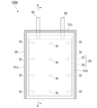
- FIG. 1 is a plan view showing a configuration of an energy storage element according to a first embodiment of the present invention
- 2 is a cross-sectional view of the energy storage element taken along line AA in FIG. 1.
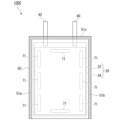
- FIG. 6 is a plan view showing a configuration of an energy storage element according to a second embodiment of the present invention.
- FIG. 11 is a plan view showing a configuration of an energy storage element according to a third embodiment of the present invention.
- FIG. 1 is a plan view showing the configuration of energy storage element 100A.
- Fig. 2 is a cross-sectional view of energy storage element 100A taken along line segment AA shown in Fig. 1.
- the energy storage element 100A of this embodiment is a lithium ion secondary battery to which the present invention is applied.
- the present invention is not necessarily limited to lithium ion secondary batteries, and any energy storage element to which the present invention can be applied may be used.
- the energy storage element 100A of this embodiment comprises a laminate 40, an exterior body 50 sealed with the laminate 40 housed therein, and an electrolyte (not shown) sealed inside the exterior body 50.
- the laminate 40 includes a positive electrode 20 and a negative electrode 30, a separator 10 between the positive electrode 20 and the negative electrode 30, a positive electrode side lead terminal 60 electrically connected to the positive electrode 20, and a negative electrode side lead terminal 62 electrically connected to the negative electrode 30.
- the positive electrode 20 has a positive electrode current collector 22 and a positive electrode active material layer 24 , and the positive electrode active material layer 24 is provided in contact with at least one surface (one surface in this embodiment) of the positive electrode current collector 22 .
- the positive electrode current collector 22 is made of, for example, a sheet-like or plate-like member having electrical conductivity. Specifically, for example, a thin plate made of a metal such as aluminum, copper, nickel, titanium, or stainless steel is used as the positive electrode current collector 22. Among them, an aluminum plate, which is light in weight, is preferably used for the positive electrode current collector 22.
- the average thickness of the positive electrode current collector 22 is, for example, about 5 to 20 ⁇ m.
- the positive electrode current collector 22 may be, for example, a conductive sheet-like or plate-like member having a surface coated with a conductive layer.
- the conductive layer may, for example, contain a conductive material, a binder, and, if desired, a thickener in a predetermined blend ratio.
- conductive materials include conductive carbon materials such as carbon black, acetylene black, graphite, carbon fiber, and carbon nanotubes.
- binders include acrylic binders, styrene butadiene rubber binders, and the like.
- An example of a thickener that can be used is carboxymethyl cellulose.
- the positive electrode current collector 22 may also be a laminate in which a metal layer is formed on the surface of a resin layer.
- the metal layer may be made of, for example, aluminum, copper, nickel, titanium, stainless steel, etc., and it is preferable to use aluminum, which is lightweight.
- the resin layer may be made of, for example, polyethylene terephthalate (PET), polyimide (PI), polyamideimide (PAI), polypropylene (PP), polyethylene (PE), etc.
- the positive electrode active material layer 24 contains at least a positive electrode active material, and may contain, for example, a conductive assistant, a binder, and the like, as necessary.
- the positive electrode active material includes an electrode active material that can reversibly absorb and release lithium ions, remove and insert lithium ions (intercalation), or dope and dedope lithium ions and counter anions.
- the positive electrode active material is, for example, a composite metal oxide (lithium-containing transition metal oxide).
- the positive electrode active material may contain, for example, any one selected from the group consisting of nickel, cobalt, manganese, and aluminum.
- the positive electrode active material may be, for example, lithium cobalt oxide using cobalt as the transition metal, or a ternary compound containing any one selected from the group consisting of nickel, cobalt, manganese, and aluminum.
- Nickel cobalt manganese oxide (NCM) and nickel cobalt aluminum oxide (NCA) are examples of ternary compounds. Lithium cobalt oxide can be used stably at a relatively high potential, and has high stability during charging and discharging. Although ternary compounds are less stable than lithium cobalt oxide, they can be used at higher potentials.
- a compound represented by LiNi 1-x-y Co x M y O z is an example of a ternary compound used for a positive electrode active material.
- This ternary compound can be used stably even at a high potential.
- M is one or more selected from the group consisting of Al, Fe, Mn, V, Cr, Ti, W, Ta, Mg, and Mo.
- x satisfies 0 ⁇ x ⁇ 0.5, preferably 0 ⁇ x ⁇ 0.5.
- y satisfies 0 ⁇ y ⁇ 0.5, preferably 0 ⁇ y ⁇ 0.5.
- the sum of x and y satisfies x+y ⁇ 1.
- z is the atomic fraction of oxygen, and is based on 2, allowing deviation from the stoichiometric composition. For example, z satisfies 1.9 ⁇ y ⁇ 2.1.
- These compounds may be used alone or in combination as the positive electrode active material.
- the particle size of the positive electrode active material varies depending on the type of active material selected.
- primary particles with a particle size of 5 to 20 ⁇ m can be used.
- secondary particles that are an aggregate of primary particles granulated to a particle size of 5 to 20 ⁇ m, or primary particles with a particle size of 5 to 20 ⁇ m can be used.
- primary particles of less than 1 ⁇ m or secondary particles granulated from these can be used.
- the positive electrode active material may be a lithium-free material.
- the lithium-free material include FeF 3 , conjugated polymers containing organic conductive materials, Chevrel phase compounds, transition metal chalcogenides, vanadium oxides, and niobium oxides.
- the lithium-free material may be any one of the materials or a combination of a plurality of materials.
- discharge is performed first. Lithium is inserted into the positive electrode active material by discharging.
- lithium may be pre-doped chemically or electrochemically into the lithium-free positive electrode active material.
- the conductive additive enhances the electronic conductivity between the positive electrode active materials.
- the conductive additive is, for example, carbon powder, carbon nanotubes, carbon material, metal powder, a mixture of carbon material and metal powder, or conductive oxide.
- the carbon powder is, for example, carbon black, acetylene black, ketjen black, etc.
- the metal powder is, for example, copper, nickel, stainless steel, etc.
- the content of the conductive additive in the positive electrode active material layer 24 is not particularly limited.
- the content of the conductive additive relative to the total mass of the positive electrode active material, the conductive additive, and the binder is 0.5 mass% or more and 20 mass% or less, and preferably 1 mass% or more and 5 mass% or less.
- the binder in the positive electrode active material layer 24 binds the positive electrode active material together. Any known binder can be used.
- the binder may be the same as that used in the negative electrode active material layer 34 described later.
- the binder is preferably one that does not dissolve in the electrolyte, has oxidation resistance, and has adhesive properties.
- the binder is, for example, a fluororesin.
- the binder is, for example, polyvinylidene fluoride (PVDF), polytetrafluoroethylene (PTFE), polyamide (PA), polyimide (PI), polyamideimide (PAI), polybenzimidazole (PBI), polyethersulfone (PES), polyacrylic acid and its copolymers, metal ion crosslinked polyacrylic acid and its copolymers, polypropylene (PP) or polyethylene (PE) grafted with maleic anhydride, or a mixture thereof.
- PVDF polyvinylidene fluoride
- PTFE polytetrafluoroethylene
- PA polyamide
- PI polyimide
- PAI polyamideimide
- PBI polybenzimidazole
- PES polyethersulfone
- PVDF polyacrylic acid and its copolymers
- metal ion crosslinked polyacrylic acid and its copolymers polypropylene (PP) or polyethylene (PE) grafted with maleic anhydride, or a
- the binder content in the positive electrode active material layer 24 is not particularly limited.
- the binder content relative to the total mass of the positive electrode active material, conductive additive, and binder is 1 mass% or more and 15 mass% or less, and preferably 1.5 mass% or more and 5 mass% or less. If the binder content is low, the adhesive strength of the positive electrode 20 will be weakened. If the binder content is high, the binder is electrochemically inactive and does not contribute to the discharge capacity, resulting in a low energy density of the lithium ion secondary battery.
- a sintered plate or a powder compact may be used as the positive electrode active material layer 24.
- a sintered plate or powder compact it is not necessary to include a conductive additive or a binder.
- the negative electrode 30 has a negative electrode current collector 32 and a negative electrode active material layer 34 , and the negative electrode active material layer 34 is provided in contact with at least one surface (one surface in this embodiment) of the negative electrode current collector 32 .
- the negative electrode current collector 32 is made of, for example, a sheet or plate member having electrical conductivity.
- the same materials as those exemplified for the positive electrode current collector 22 can be used. Among them, a copper plate that does not react with lithium at low potential is preferably used for the negative electrode current collector 32.
- the average thickness of the negative electrode current collector 32 is, for example, about 5 to 20 ⁇ m.
- the negative electrode active material layer 34 contains at least a negative electrode active material, and may contain a conductive assistant, a thickener, a binder, and the like, as necessary.
- the negative electrode active material may be any compound capable of absorbing and releasing ions, and may be any negative electrode active material used in known lithium ion secondary batteries.
- the negative electrode active material may be, for example, metallic lithium, lithium alloy, carbon material, material capable of alloying with lithium, titanium oxide (TiO x ), or lithium titanate (LiTiO 2 , Li 4 Ti 5 O 12 ).
- the material capable of alloying with lithium may include, for example, silicon, tin, zinc, lead, or antimony.
- the material capable of alloying with lithium may be, for example, these simple metals, or alloys or oxides containing these elements.
- the negative electrode active material includes, for example, a carbon material.
- carbon materials include graphite (natural graphite, artificial graphite), which can absorb and release ions, carbon nanotubes, difficult-to-graphitize carbon, easy-to-graphitize carbon, and low-temperature fired carbon.
- graphite naturally graphite, artificial graphite
- graphite can increase the battery voltage because the reaction accompanying the insertion and desorption of lithium ions is lower than the standard redox potential of lithium.
- the negative electrode active material includes, for example, lithium titanate (LiTiO 2 , Li 4 Ti 5 O 12 ).
- Li 4 Ti 5 O 12 has a constant reaction potential associated with the desorption and insertion of lithium ions, a small volume change, and high thermal stability.
- the negative electrode active material includes, for example, silicon.
- the silicon may be elemental silicon or a silicon compound.
- the silicon compound may be, for example, a silicon alloy, silicon oxide, etc.
- the silicon may be crystalline or amorphous.
- Amorphous silicon or silicon compounds can be produced by a melt-spun method, a gas atomization method, etc.
- the silicon alloy is represented by XnSi.
- X is a cation.
- X is, for example, Ba, Mg, Al, Zn, Sn, Ca, V, Cr, Mn, Fe, Co, Ni, Cu, Zn, Ge, Y, Zr, Nb, Mo, W, Au, Ti, Na, K, etc.
- n satisfies 0 ⁇ n ⁇ 0.5.
- Silicon oxide is represented by SiO x . x satisfies, for example, 0.8 ⁇ x ⁇ 2.
- Silicon oxide may be made of only SiO 2 , may be made of only SiO, or may be a mixture of SiO and SiO 2. Silicon oxide may also be partially deficient in oxygen.
- the negative electrode active material may be a composite of silicon or a silicon compound.
- the composite is a silicon or silicon compound particle having at least a part of its surface coated with a conductive material.
- the conductive material is, for example, a carbon material, Al, Ti, Fe, Ni, Cu, Zn, Ag, Sn, etc.
- a silicon carbon composite material Si-C
- the amount of conductive material coated on the silicon or silicon compound particle is, for example, 0.01 mass% or more and 30 mass% or less, and preferably 0.1 mass% or more and 20 mass% or less, based on the total mass of the composite.
- the composite can be produced, for example, by mechanical alloying, chemical vapor deposition, wet method, or a method of coating with a polymer and then pyrolyzing the polymer to carbonize it.
- the negative electrode active material layer 34 may contain, for example, lithium as described above.
- the lithium may be metallic lithium or a lithium alloy.
- the negative electrode active material layer 34 may be metallic lithium or a lithium alloy.
- the lithium alloy is, for example, an alloy of lithium and one or more elements selected from the group consisting of Si, Sn, C, Pt, Ir, Ni, Cu, Ti, Na, K, Rb, Cs, Fr, Be, Mg, Ca, Sr, Sb, Pb, In, Zn, Ba, Ra, Ge, and Al.
- the negative electrode active material when the negative electrode active material is metallic lithium, the negative electrode 30 may be called a Li negative electrode.
- the negative electrode active material layer 34 may be a sheet of lithium.
- the negative electrode 30 may not have the negative electrode active material layer 34 during fabrication, and may only have the negative electrode current collector 32.
- metallic lithium is precipitated on the surface of the negative electrode current collector 32.
- Metallic lithium is elemental lithium with lithium ions precipitated therein, and metallic lithium functions as the negative electrode active material layer 34.
- the conductive assistant and binder may be the same as those exemplified for the positive electrode 20.
- the binder in the negative electrode 30 may be, for example, cellulose, styrene-butadiene rubber, ethylene-propylene rubber, polyimide resin, polyamide-imide resin, acrylic resin, or the like, in addition to those exemplified for the positive electrode 20.
- the cellulose may be, for example, carboxymethyl cellulose (CMC).
- CMC carboxymethyl cellulose
- a sintered plate or a green compact green compact
- the separator 10 is disposed in a sandwiched state between the positive electrode 20 and the negative electrode 30, thereby dividing the inside of the outer casing 50 into a space on the positive electrode 20 side (positive electrode chamber) and a space on the negative electrode 30 side (negative electrode chamber).
- the separator 10 separates the positive electrode 20 and the negative electrode 30, preventing short circuits between the positive electrode 20 and the negative electrode 30 while allowing lithium ions to pass through.
- the separator 10 includes a microporous membrane.
- the microporous membrane insulates the positive and negative electrodes by retaining an electrolyte, and allows only lithium ions to pass through.
- the microporous membrane is, for example, a monolayer or laminate of polyolefin film.
- the separator 10 may be a stretched membrane of a mixture of polyethylene, polypropylene, or the like.
- the microporous membrane may be, for example, a fibrous nonwoven fabric made of at least one constituent material selected from the group consisting of cellulose, polyester, polyacrylonitrile, polyamide, polyethylene, and polypropylene.
- the separator 10 may be provided with an inorganic coated separator.
- the inorganic coated separator is formed by applying a mixture of a resin such as PVDF or CMC and an inorganic material such as alumina or silica to the surface of the above-mentioned film.
- the inorganic coated separator has excellent heat resistance and prevents the transition metal eluted from the positive electrode 20 from precipitating on the surface of the negative electrode 30.
- the separator 10 is not limited to a configuration including only the microporous membrane described above, and may be configured, for example, as a laminate of a microporous membrane and another layer. Specifically, the separator 10 may be, for example, a laminate of a microporous membrane and a solid electrolyte layer.
- the solid electrolyte layer does not allow the electrolyte to pass through, but allows only lithium ions to pass through.
- the solid electrolyte layer separates the electrolyte in the positive electrode chamber from the electrolyte in the negative electrode chamber, preventing them from becoming miscible.
- the solid electrolyte layer contains a solid electrolyte. Examples of solid electrolytes include polymer solid electrolytes, oxide-based solid electrolytes, and sulfide-based solid electrolytes.
- the solid electrolyte is, for example, a phosphate having a NASICON structure.
- the solid electrolyte is, for example, Li 1+s+u D s (E t Ti 1-t ) 2-s (SiO 4 ) u (PO 4 ) 3-u .
- D is trivalent aluminum or gallium
- E is tetravalent germanium or zirconium, and satisfies 0 ⁇ s ⁇ 0.8, 0 ⁇ t ⁇ 1, and 0 ⁇ u ⁇ 0.5.
- This solid electrolyte has low reactivity with the electrolytic solution and is unlikely to cause excessive decomposition of the electrolytic solution or electrolyte salt.
- the non-aqueous electrolyte contains a salt (electrolyte) and a non-aqueous solvent.
- the non-aqueous solvent may contain a cyclic carbonate and a chain carbonate.
- the ratio of the cyclic carbonate to the chain carbonate in the non-aqueous solvent is preferably 1:9 to 1:1 by volume.
- the cyclic carbonate used is one that can solvate the electrolyte.
- ethylene carbonate, propylene carbonate, and butylene carbonate are used as the cyclic carbonate.
- Linear carbonates reduce the viscosity of cyclic carbonates.
- diethyl carbonate, dimethyl carbonate, ethyl methyl carbonate, etc. are used as linear carbonates.
- linear esters such as methyl acetate, ethyl acetate, methyl propionate, ethyl propionate, etc.
- cyclic esters such as gamma-butyrolactone, nitriles such as acetonitrile, propionitrile, glutaronitrile, adiponitrile, 1,2-dimethoxyethane, 1,2-diethoxyethane, etc. may be mixed and used.
- the non-aqueous solvent preferably contains 50% by mass or more and 85% by mass or less of a low-boiling solvent having a boiling point of 130°C or less, more preferably 60% by mass or more and 85% by mass or less, and even more preferably 70% by mass or more and 85% by mass or less.
- the non-aqueous solvent preferably contains 35% by mass or more and 85% by mass or less of a low-boiling solvent having a boiling point of 110°C or less, more preferably 45% by mass or more and 85% by mass or less, and even more preferably 55% by mass or more and 85% by mass or less.
- the non-aqueous solvent contains a low-boiling point solvent
- the amount of gas discharged from the exterior body 50 when the exterior body 50 is cleaved can be increased.
- Increasing the amount of discharged gas promotes the cooling effect due to the latent heat of vaporization.
- the laminate 40 can be cooled by the discharged gas, and abnormal heat generation of the laminate 40 can be suppressed.
- Metal salts can be used as the electrolyte.
- lithium salts such as LiPF6 , LiClO4, LiBF4 , LiCF3SO3 , LiCF3CF2SO3 , LiC ( CF3SO2 ) 3 , LiN ( CF3SO2 ) 2 , LiN( CF3CF2SO2 ) 2 , LiN( CF3SO2 ) ( C4F9SO2 ) , LiN( CF3CF2CO ) 2 , and LiBOB can be used.
- These lithium salts may be used alone or in combination of two or more.
- the concentration of the electrolyte in the non-aqueous electrolyte is 0.5 to 2.0 mol/L.
- concentration of the electrolyte is 0.5 mol/L or more, the lithium ion concentration of the non-aqueous electrolyte can be sufficiently ensured, and sufficient capacity can be easily obtained during charging and discharging.
- the viscosity increase of the non-aqueous electrolyte can be suppressed, the mobility of the lithium ions can be sufficiently ensured, and sufficient capacity can be easily obtained during charging and discharging.
- the lithium ion concentration in the nonaqueous electrolyte it is preferable to adjust the lithium ion concentration in the nonaqueous electrolyte to 0.5 to 2.0 mol/L, and it is more preferable that the lithium ion concentration from LiPF6 is 50 mol% or more.
- the non-aqueous electrolyte may be a gel electrolyte held in a polymer material.
- polymer materials include polyvinylidene fluoride and copolymers of polyvinylidene fluoride, and examples of copolymer monomers include hexafluoropropylene and tetrafluoroethylene.
- Polyvinylidene fluoride and its copolymers are preferred because they can provide high battery characteristics.
- polymeric materials that can be used include polyacrylonitrile and copolymers of polyacrylonitrile, and examples of copolymer monomers, such as vinyl monomers, include vinyl acetate, methyl methacrylate, butyl methacrylate, methyl acrylate, butyl acrylate, itaconic acid, hydrogenated methyl acrylate, hydrogenated ethyl acrylate, acrylamide, vinyl chloride, vinylidene fluoride, and vinylidene chloride.
- acrylonitrile butadiene rubber examples include acrylonitrile butadiene rubber, acrylonitrile butadiene styrene resin, acrylonitrile chlorinated polyethylene propylene diene styrene resin, acrylonitrile chlorinated polyethylene propylene diene styrene resin, acrylonitrile vinyl chloride resin, acrylonitrile methacrylate resin, and acrylonitrile acrylate resin.
- the polymer material may be, for example, polyethylene oxide or a copolymer of polyethylene oxide, and examples of the copolymerization monomer include polypropylene oxide, methyl methacrylate, butyl methacrylate, methyl acrylate, or butyl acrylate.
- polyether-modified siloxane and its copolymer may be used.
- the exterior body 50 includes a laminate film, and the laminate film is overlapped and the peripheral edges of the two films are bonded together by heat fusion (heat sealing), thereby sealing the laminate 40 .
- a single rectangular laminate film 50a is folded in half and laminated together, and the peripheral edges of the side portions (a pair of side edges) are bonded together to form a pair of side edge seal portions 51a, 51b, and the peripheral edges of the upper portions are bonded together to form an upper edge seal portion 51c.
- two rectangular laminate films may be overlapped.
- a pair of side edge seal portions are formed by bonding the peripheral edges of the sides of each film together
- a lower edge seal portion is formed by bonding the peripheral edges of the lower sides of each film together
- an upper edge seal portion is formed by bonding the peripheral edges of the upper sides of each film together.
- the exterior body 50 is made of a laminate film 50a in which a metal foil 52 is coated on both sides with a resin layer 54.
- the metal foil 52 is, for example, aluminum foil.
- the resin layer 54 is made of a polymer film such as polypropylene.
- the resin layer 54 may be different on the inner side and the outer side of the metal foil 52.
- the resin layer 54 on the outer side may be made of a polymer with a high melting point, such as polyethylene terephthalate (PET) or polyamide (PA), and the resin layer 54 on the inner side may be made of polyethylene (PE) or polypropylene (PP).
- PET polyethylene terephthalate
- PA polyamide
- PE polyethylene
- PP polypropylene
- a thin metal plate made of, for example, aluminum, nickel, copper, or the like is used for the positive electrode lead terminal 60 and the negative electrode lead terminal 62.
- the positive electrode lead terminal 60 and the negative electrode lead terminal 62 may be protected with insulating tape to prevent short-circuiting between them.
- the positive electrode lead terminal 60 has one end connected to the positive electrode collector 22.
- the negative electrode lead terminal 62 has one end connected to the negative electrode collector 32.
- the other end of the positive electrode lead terminal 60 and the other end of the negative electrode lead terminal 62 are led out from the bonding portion (upper edge seal portion 51c) of the laminate film described above to the outside of the exterior body 50. This allows the energy storage element 100A to be electrically connected to the outside via the positive electrode lead terminal 60 and the negative electrode lead terminal 62.
- the above-mentioned positive electrode 20 has a structure in which the positive electrode active material layer 24 is joined to one surface of the positive electrode collector 22 via a plurality of joints 70 provided within the surface of the positive electrode collector 22.
- the negative electrode 30 has a structure in which the negative electrode active material layer 34 is joined to one surface of the negative electrode collector 32 via a plurality of joints 70 provided within the surface of the negative electrode collector 32.
- joint 70 on the positive electrode 20 side and the joint 70 on the negative electrode 30 side basically have the same structure, only the joint 70 on the positive electrode 20 side shown in FIG. 1 will be described, and a description of the joint 70 on the negative electrode 30 side will be omitted.
- the joint 70 bonds the positive electrode collector 22 and the positive electrode active material layer 24 via an adhesive (bonding agent).
- an adhesive bonding agent
- the adhesive there are no particular limitations on the adhesive, and any known or commercially available adhesive may be used, but it is preferable that the adhesive be conductive to prevent an increase in resistance between the positive electrode collector 22 and the positive electrode active material layer 24.
- the adhesive may, for example, contain a conductive material, a binder, and, if desired, a thickener in a predetermined mixing ratio.
- the conductive material may, for example, be conductive carbon materials such as carbon black, acetylene black, graphite, carbon fiber, and carbon nanotubes.
- the binder may, for example, be an acrylic binder, a styrene butadiene rubber binder, and the like.
- the thickener may, for example, be carboxymethyl cellulose, and the like.
- the joint 70 may use a method other than the adhesive described above to join (fix) the positive electrode collector 22 and the positive electrode active material layer 24 together.
- the multiple joints 70 are formed in a dot-like pattern and are arranged at intervals in a first direction and a second direction that intersect with each other within the plane of the positive electrode collector 22. In other words, the multiple joints 70 are arranged linearly in the first direction and the second direction within the plane of the positive electrode collector 22. It can also be said that the multiple joints 70 are arranged linearly on a line extending in the first direction and the second direction.
- joints 70 are arranged in the vertical direction (up and down direction) of the positive electrode 20, and three joints 70 are arranged in the horizontal direction (left and right direction) in a lattice pattern in a first direction and a second direction that are perpendicular to each other within the plane.
- the joint 70 is formed in a circular shape when viewed from above.
- the shape of the joint 70 is not limited to this shape, and may be, for example, an elliptical shape or a polygonal shape (e.g., a triangle, a square, a pentagon, a hexagon, a heptagon, an octagon), etc.
- the ratio (hereinafter referred to as "area ratio”) of the sum E2 of the area of the positive electrode active material layer 24 that is joined to one side of the positive electrode collector 22 via the multiple joints 70 (hereinafter referred to as “joint area”) to the sum E1 of the area of the positive electrode active material layer 24 that is in contact with one side of the positive electrode collector 22 (hereinafter referred to as "contact area”) is preferably 2 to 30%, and more preferably 5 to 20%.
- this area ratio is less than 2%, there is a high possibility that the positive electrode active material layer 24 will peel off from the positive electrode collector 22 due to insufficient adhesion when the positive electrode collector 22 and the positive electrode active material layer 24 are partially bonded (joined) together. On the other hand, if this area ratio exceeds 30%, stress relaxation due to volumetric changes in the positive electrode active material layer 24 when charging and discharging are repeated will be insufficient.
- the energy storage element 100A of this embodiment having the above-mentioned configuration, even if the current collectors 22, 32 and the active material layers 24, 34 are partially bonded in the positive electrode 20 and the negative electrode 30 described above, it is possible to suppress deterioration of the active material layers 24, 34 while maintaining the bonding strength between the current collectors 22, 32 and the active material layers 24, 34.
- FIG. 3 is a plan view showing the configuration of the energy storage element 100B.
- the description of the same parts as those in the energy storage element 100A will be omitted and the same reference numerals will be used in the drawings.
- the energy storage element 100B of this embodiment has basically the same configuration as the energy storage element 100A described above, except that the arrangement of the multiple joints 70 is different.
- three or two joints 70 are arranged in the vertical direction (up-down direction) of the positive electrode 20, and two or one joint 70 are arranged in the horizontal direction (left-right direction) in a staggered manner in a first direction and a second direction that intersect with each other within the plane.
- the area ratio (E2/E1 x 100) of the total bonding area E2 of the positive electrode active material layer 24 bonded to one surface of the positive electrode collector 22 via the multiple bonding portions 70 to the total contact area E1 of the positive electrode active material layer 24 in contact with one surface of the positive electrode collector 22 described above is in the range of 2 to 30%.
- the joint 70 on the positive electrode 20 side and the joint 70 on the negative electrode 30 side basically have the same structure, so a description of the joint 70 on the negative electrode 30 side will be omitted.
- the energy storage element 100B of this embodiment having the above-mentioned configuration, as in the energy storage element 100A described above, even if the current collectors 22, 32 and the active material layers 24, 34 in the positive electrode 20 and the negative electrode 30 are partially bonded, respectively, it is possible to suppress deterioration of the active material layers 24, 34 while maintaining the bonding strength between the current collectors 22, 32 and the active material layers 24, 34.
- FIG. 4 is a plan view showing the configuration of the energy storage element 100C.
- the description of the same parts as those in the energy storage element 100A will be omitted and the same reference numerals will be used in the drawings.
- the positive electrode 20 has a structure in which the positive electrode active material layer 24 is joined to one surface of the positive electrode collector 22 via a plurality of joints 71 provided within the surface of the positive electrode collector 22.
- the negative electrode 30 has a structure in which the negative electrode active material layer 34 is joined to one surface of the negative electrode collector 32 via a plurality of joints 71 provided within the surface of the negative electrode collector 32.
- the energy storage element 100C of this embodiment has a configuration in which linear (line-shaped) joints 71 are arranged instead of the point-shaped joints 70 described above. Other than that, it has basically the same configuration as the energy storage element 100A described above.
- the joints 71 are formed in a straight line with a predetermined width, and are arranged in a row along the periphery of the positive electrode collector 22.
- three joints 71 each extending vertically (up and down) along both side ends of the positive electrode collector 22, and one joint 71 each extending horizontally (left and right) along the upper end and lower end of the positive electrode collector 22 are arranged in a frame shape surrounding the periphery of the positive electrode collector 22.
- the joint 71 is not limited to the linear shape described above, but may be, for example, curved along the corner of the positive electrode collector 22, or may be frame-shaped so as to surround the positive electrode collector 22.
- the width and length of the joint 71 may also be adjusted as appropriate.
- the area ratio (E2/E1 x 100) of the total bonding area E2 of the positive electrode active material layer 24 bonded to one surface of the positive electrode collector 22 via the multiple bonding portions 71 to the total contact area E1 of the positive electrode active material layer 24 in contact with one surface of the positive electrode collector 22 described above is in the range of 2 to 30%.
- the joint 71 on the positive electrode 20 side and the joint 71 on the negative electrode 30 side basically have the same structure, so a description of the joint 71 on the negative electrode 30 side will be omitted.
- the energy storage element 100C of this embodiment having the above-mentioned configuration, as in the energy storage element 100A described above, even if the current collectors 22, 32 and the active material layers 24, 34 in the positive electrode 20 and the negative electrode 30 are partially bonded, respectively, it is possible to suppress deterioration of the active material layers 24, 34 while maintaining the bonding strength between the current collectors 22, 32 and the active material layers 24, 34.
- the energy storage elements 100A to 100C are configured with one laminate 40, but multiple laminates 40 may be stacked and enclosed inside the exterior body 50.
- the present invention can be applied to either or both of the positive electrode 20 and the negative electrode 30 described above, and can be implemented by appropriately changing the arrangement, number, size, etc. of the above-mentioned joints 70, 71 between the positive electrode 20 and the negative electrode 30.
- the term "energy storage element” is a concept that encompasses both batteries (lithium ion batteries, nickel-metal hydride batteries, etc.) and capacitors (electric double layer capacitors, etc.).
- Example 1 In Example 1, first, a positive electrode slurry was applied to one surface of a PET film having a thickness of 15 ⁇ m.
- the positive electrode slurry was prepared by mixing a positive electrode active material, a binder, and a solvent.
- the positive electrode active material was LiCoO2 , the binder was ethyl cellulose, and the solvent was dihydroterpineol.
- a positive electrode slurry was prepared by mixing 97 parts by mass of a positive electrode active material, 3 parts by mass of a binder, and 70 parts by mass of a solvent.
- the amount of the positive electrode active material carried in the positive electrode active material layer after drying was 15 mg/cm 2.
- the solvent was removed from the positive electrode slurry in a drying furnace, and a molded body of the positive electrode slurry was prepared on a PET film.
- the molded body of the positive electrode slurry was placed on a zirconia setter and heat-treated at 800° C. for 6 hours to prepare a positive electrode active material layer.
- the resulting positive electrode active material layer was attached to one side of a 10 ⁇ m thick aluminum foil (current collector) via a joint to produce a positive electrode.
- the negative electrode slurry was applied to one side of a 10 ⁇ m thick copper foil (current collector).
- the negative electrode slurry was made by mixing the negative electrode active material, a thickener, a binder, and a solvent.
- Graphite was used as the negative electrode active material.
- Sodium carboxymethyl cellulose (CMC) was used as the thickener.
- Styrene butadiene rubber (SBR) was used as the binder. Distilled water was used as the solvent.
- a negative electrode slurry was prepared by mixing 95 parts by mass of the negative electrode active material, 3 parts by mass of a thickener, 2 parts by mass of a binder, and distilled water. The amount of the negative electrode active material carried in the negative electrode active material layer after drying was 9.0 mg/cm 2. The solvent was removed from the negative electrode slurry in a drying furnace to prepare a negative electrode active material layer. The negative electrode active material layer was pressed with a roll press to prepare a negative electrode.
- electrolyte solution was prepared.
- a mixed solvent of ethylene carbonate (EC):diethyl carbonate (DEC) in a volume ratio of 3:7 was used as the electrolyte solution.
- LiPF6 was dissolved in the solvent as an electrolyte salt to a concentration of 1.0 mol/L.
- an aluminum positive electrode lead terminal was attached to the positive electrode, and a nickel negative electrode lead terminal was attached to the negative electrode.
- the positive electrode lead terminal and the negative electrode lead terminal were welded together using an ultrasonic welding machine.
- the positive and negative electrodes were stacked with a separator between them so that the positive and negative active material layers faced each other to produce a laminate.
- a 12 ⁇ m thick porous polypropylene sheet was used as the separator.
- a sheet of aluminum laminate film was folded in half and layered, and the peripheral edges of the three opposing sides (a pair of side edges) excluding the upper edge were bonded together by heat fusion (heat sealing) to create the exterior body.
- the laminate was inserted into the exterior body with the positive electrode lead terminal and the negative electrode lead terminal extending from the upper opening of the exterior body to the outside.
- an electrolyte was injected, and the upper edge was bonded by heat sealing while reducing the pressure inside the exterior body with a vacuum sealer. This sealed the laminate inside the exterior body.
- Example 1 the total contact area E1 between the current collector and the positive electrode active material layer in the positive electrode was 3000 mm 2 (60 mm long ⁇ 50 mm wide).
- the total contact area E1 was defined as the area where the current collector and the positive electrode active material layer overlap in a plan view.
- the joint was formed in the shape of a circular dot with a radius of 2.5 mm, and three joints were arranged in a line extending vertically through the center of the current collector. The three joints bonded the positive electrode active material layer and the current collector.
- the total joint area E2 of the multiple joints was 58.88 mm2 .
- Example 1 the area ratio (E2/E1 x 100) of the total contact area E2 of the multiple joints to the total contact area E1 between the current collector and the positive electrode active material layer in the positive electrode was 2.0%.
- the total contact area E1 between the current collector and the negative electrode active material layer was 3000 mm2 (60 mm length ⁇ 50 mm width). Since the current collector and the negative electrode active material layer were not bonded to each other by a joint, the total contact area E2 by the joint was 0 mm2 , and the area ratio (E2/E1 ⁇ 100) was 0%.
- Example 2 to 15 In Examples 2 to 15, the radius, number, and arrangement of the circular dot-like joints in the positive electrode were changed, and the area ratio (E2/E1 ⁇ 100) was changed within the range of this embodiment (2 to 30%). Except for this, lithium ion secondary batteries were produced in the same manner as in Example 1.
- Comparative Examples 1 to 4 In Comparative Examples 1 to 4, the radius, number, and arrangement of the circular dot-like joints in the positive electrode were changed, and the area ratio (E2/E1 ⁇ 100) was changed outside the range of this embodiment (2 to 30%). Except for this, lithium ion secondary batteries were produced in the same manner as in Example 1.
- Example 16 In Example 16, the positive electrode had a linear joint having a width of 2 mm, and one joint was disposed along each of the upper and lower ends of the current collector. The positive electrode active material layer and the current collector were bonded together by these two joints. A lithium ion secondary battery was fabricated in the same manner as in Example 1, except for these joints.
- the total bonding area E2 of the multiple bonding parts was 200 mm2 .
- the area ratio (E2/E1 ⁇ 100) of the total bonding area E2 of the multiple bonding parts to the total contact area E1 between the current collector and the active material layer in the positive electrode was 6.7%.
- Example 17 In Example 17, the positive electrode had a linear joint having a width of 2 mm, and one joint was disposed along each of the left and right ends of the current collector. The positive electrode active material layer and the current collector were bonded together by these two joints. A lithium ion secondary battery was fabricated in the same manner as in Example 1, except for these joints.
- Example 18 In Example 18, the positive electrode had a linear joint with a width of 1 mm, and one joint was arranged along the periphery (top end, bottom end, left end, and right end) of the current collector. This single joint bonded the positive electrode active material layer to the current collector. A lithium ion secondary battery was produced in the same manner as in Example 1, except for this joint.
- Example 19 A lithium ion secondary battery was produced in the same manner as in Example 18, except that the width of the joint portion was changed and the area ratio (E2/E1 ⁇ 100) was changed within the range of this embodiment (2 to 30%).
- Comparative Examples 5 and 6 In Comparative Examples 5 and 6, the width of the linear joint portion in the positive electrode was changed, and the area ratio (E2/E1 ⁇ 100) was changed outside the range of this embodiment (2 to 30%). Except for this, lithium ion secondary batteries were produced in the same manner as in Example 16.
- Comparative Examples 7 and 8 In Comparative Examples 7 and 8, the width of the linear joint portion in the positive electrode was changed, and the area ratio (E2/E1 ⁇ 100) was changed outside the range of this embodiment (2 to 30%). Except for this, a lithium ion secondary battery was produced in the same manner as in Example 17.
- Comparative Example 9 a lithium ion secondary battery was produced in the same manner as in Example 18, except that the width of the linear joint in the positive electrode was changed and the area ratio (E2/E1 ⁇ 100) was changed outside the range of this embodiment (2 to 30%).
- the battery was charged (CC charging) at a constant current charge rate of 0.1 C (a current value at which charging at a constant current of 1 mA at 25° C. ends in 10 hours) until the battery voltage reached 4.3 V, and then charged (CV charging) until the current value reached 0.05 C.
- the battery was discharged (CC discharging) at a constant current discharge rate of 0.1 C until the battery voltage reached 2.8 V.
- the battery was charged (CC charging) at a constant current charge rate of 0.5 C until the battery voltage reached 4.3 V, and then charged (CV charging) until the current value reached 0.05 C.
- the battery was then discharged (CC discharging) at a constant current discharge rate of 0.5 C until the battery voltage reached 2.8 V.
- the discharge capacity (mAh) after the completion of charging and discharging was detected, and the discharge capacity Q1 of the first cycle was calculated.
- the battery for which the discharge capacity Q1 was determined was again charged (CC charge) at a constant current charge rate of 0.5 C until the battery voltage reached 4.3 V, and then charged (CV charge) until the current value reached 0.05 C. Then, discharged (CC discharge) at a constant current discharge rate of 0.1 C until the battery voltage reached 2.8 V.
- the above charge and discharge were counted as one cycle, and 500 cycles of charge and discharge were performed. After that, the discharge capacity (mAh) after discharge after the completion of 500 cycles of charge and discharge was detected, and the discharge capacity Q2 was determined.
- Example 22 In Example 22, first, one surface of an aluminum foil (current collector) having a thickness of 15 ⁇ m was coated with a positive electrode slurry.
- the positive electrode slurry was prepared by mixing a positive electrode active material, a conductive assistant, a binder, and a solvent.
- the positive electrode active material was LiCoO2 .
- the conductive additive was acetylene black.
- the binder was polyvinylidene fluoride (PVDF).
- the solvent was N-methyl-2-pyrrolidone.
- a positive electrode slurry was prepared by mixing 97 parts by mass of a positive electrode active material, 1 part by mass of a conductive assistant, 2 parts by mass of a binder, and 70 parts by mass of a solvent.
- the amount of the positive electrode active material carried in the positive electrode active material layer after drying was set to 15 mg/ cm2 .
- the solvent was removed from the positive electrode slurry in a drying furnace to prepare a positive electrode active material layer.
- the positive electrode active material layer was pressed with a roll press to prepare a positive electrode.
- the negative electrode slurry was applied to one side of a 15 ⁇ m thick PET film.
- the negative electrode slurry was made by mixing the negative electrode active material, binder, and solvent.
- the negative electrode active material was Li 4 Ti 5 O 12.
- the binder was ethyl cellulose.
- the solvent was dihydroterpineol.
- a negative electrode slurry was prepared by mixing 93 parts by mass of the negative electrode active material, 7 parts by mass of the binder, and 70 parts by mass of the solvent.
- the amount of the negative electrode active material carried in the negative electrode active material layer after drying was 18 mg/cm 2.
- the solvent was removed from the negative electrode slurry in a drying furnace, and a molded body of the negative electrode slurry was prepared on a PET film.
- the molded body of the negative electrode slurry was placed on a zirconia setter from the PET film and heat-treated at 1000° C. for 6 hours to prepare a negative electrode active material layer.
- the negative electrode was fabricated by bonding the obtained negative electrode active material layer to one side of a 10 ⁇ m thick aluminum foil (current collector) via a joint.
- Example 22 a lithium ion secondary battery was fabricated in the same manner as in Example 1, except that the positive electrode and the negative electrode were changed and the current collector and the negative electrode active material layer were joined via a joint in the negative electrode.
- Example 22 the total contact area E1 between the current collector and the negative electrode active material layer in the negative electrode was 3000 mm 2 (60 mm long ⁇ 50 mm wide).
- the total contact area E1 was defined as the area where the current collector and the negative electrode active material layer overlap in a plan view.
- the joint was formed in the shape of a circular dot with a radius of 2.5 mm, and three joints were arranged in a line extending vertically through the center of the current collector. These three joints bonded the negative electrode active material layer and the current collector.
- the total joint area E2 of the multiple joints was 58.88 mm2 .
- Example 22 the area ratio (E2/E1 x 100) of the total contact area E2 of the multiple joints to the total contact area E1 between the current collector and the negative electrode active material layer in the negative electrode was 2.0%.
- the total contact area E1 between the current collector and the positive electrode active material layer was 3000 mm2 (60 mm length ⁇ 50 mm width). Since the current collector and the positive electrode active material layer were not bonded to each other by a joint, the total contact area E2 by the joint was 0 mm2 , and the area ratio (E2/E1 ⁇ 100) was 0%.
- Example 23 to 42 Comparative Examples 10 to 18
- the width, number, and arrangement of the linear (linear) joints in the negative electrode were changed, and the area ratio (E2/E1 ⁇ 100) was changed within the range of this embodiment (2 to 30%). Except for this, lithium ion secondary batteries were produced in the same manner as in Example 22.
- lithium ion secondary batteries were fabricated in the same manner as in Example 22, except that the width, number, and arrangement of the linear (linear) joints in the negative electrode were changed, and the area ratio (E2/E1 x 100) was changed outside the range of this embodiment (2 to 30%).
- the battery was charged (CC charging) at a constant current charge rate of 0.1 C (a current value at which charging is completed in 10 hours when charging at a constant current of 1 mA at 25° C.) until the battery voltage reached 3.0 V, and then charged (CV charging) until the current value reached 0.05 C.
- the battery was then discharged (CC discharging) at a constant current discharge rate of 0.1 C until the battery voltage reached 1.5 V.
- the battery was charged (CC charging) at a constant current charge rate of 0.5 C until the battery voltage reached 3.0 V, and then charged (CV charging) until the current value reached 0.05 C.
- the battery was then discharged (CC discharging) at a constant current discharge rate of 0.5 C until the battery voltage reached 1.5 V.
- the discharge capacity (mAh) after the completion of charging and discharging was detected, and the discharge capacity Q1 of the first cycle was calculated.
- the battery for which the discharge capacity Q1 was determined was again charged (CC charge) at a constant current charge rate of 0.5 C until the battery voltage reached 3.0 V, and then charged (CV charge) until the current value reached 0.05 C. Then, discharged (CC discharge) at a constant current discharge rate of 0.1 C until the battery voltage reached 1.5 V. The above charge and discharge were counted as one cycle, and 500 cycles of charge and discharge were performed. After that, the discharge capacity (mAh) after discharge after the completion of 500 cycles of charge and discharge was detected, and the discharge capacity Q2 was determined. From the determined discharge capacities Q 1 and Q 2 , the capacity retention rate Q after 500 cycles was determined using the following formula.
- Q (%) (Q 2 /Q 1 ) ⁇ 100
- Example 43 a lithium ion secondary battery was produced in the same manner as in Examples 1 and 22, except that the positive electrode produced in Example 1 shown in Table 1 and the negative electrode produced in Example 22 shown in Table 3 were used in combination.
- the contact area E1, bonding area E2, and area ratio (E2/E1 ⁇ 100) of the positive electrode were the same as the contact area E1, bonding area E2, and area ratio (E2/E1 ⁇ 100) of the negative electrode, respectively.
- Example 44 to 63 and Comparative Examples 19 to 27 In Examples 44 to 63 and Comparative Examples 19 to 27, the positive electrodes prepared in Examples 2 to 21 and Comparative Examples 1 to 9 shown in Tables 1 and 2 and the negative electrodes prepared in Examples 23 to 42 and Comparative Examples 10 to 18 shown in Tables 3 and 4 were used in combination in sequence, except that lithium ion secondary batteries were prepared in the same manner as in Example 43. For example, in Example 44, the positive electrode of Example 2 and the negative electrode of Example 23 were used in combination.
- the battery was charged (CC charging) at a constant current charge rate of 0.1 C (a current value at which charging is completed in 10 hours when charging at a constant current of 1 mA at 25° C.) until the battery voltage reached 3.0 V, and then charged (CV charging) until the current value reached 0.05 C.
- the battery was then discharged (CC discharging) at a constant current discharge rate of 0.1 C until the battery voltage reached 1.5 V.
- the battery was charged (CC charging) at a constant current charge rate of 0.5 C until the battery voltage reached 3.0 V, and then charged (CV charging) until the current value reached 0.05 C.
- the battery was then discharged (CC discharging) at a constant current discharge rate of 0.5 C until the battery voltage reached 1.5 V.
- the discharge capacity (mAh) after the completion of charging and discharging was detected, and the discharge capacity Q1 of the first cycle was calculated.
- the battery for which the discharge capacity Q1 was determined was again charged (CC charge) at a constant current charge rate of 0.5 C until the battery voltage reached 3.0 V, and then charged (CV charge) until the current value reached 0.05 C. Then, discharged (CC discharge) at a constant current discharge rate of 0.1 C until the battery voltage reached 1.5 V. The above charge and discharge were counted as one cycle, and 500 cycles of charge and discharge were performed. After that, the discharge capacity (mAh) after discharge after the completion of 500 cycles of charge and discharge was detected, and the discharge capacity Q2 was determined. From the determined discharge capacities Q 1 and Q 2 , the capacity retention rate Q after 500 cycles was determined using the following formula.
- Q (%) (Q 2 /Q 1 ) ⁇ 100
- the electrode of this embodiment is suitable for use as an electrode for batteries such as lithium ion secondary batteries and nickel-metal hydride batteries, and as an electrode for capacitors such as electric double layer capacitors.
- 10...separator 20...positive electrode, 22...positive electrode current collector, 24...positive electrode active material layer, 30...negative electrode, 32...negative electrode current collector, 34...negative electrode active material layer, 40...laminated body, 50...exterior body, 52...metal foil, 54...resin layer, 60...positive electrode lead terminal, 62...negative electrode lead terminal, 70...point-like joint, 71...linear joint, 100A, 100B, 100C...electric storage element.
Landscapes
- Chemical & Material Sciences (AREA)
- Chemical Kinetics & Catalysis (AREA)
- Electrochemistry (AREA)
- General Chemical & Material Sciences (AREA)
- Engineering & Computer Science (AREA)
- Materials Engineering (AREA)
- Inorganic Chemistry (AREA)
- Power Engineering (AREA)
- Microelectronics & Electronic Packaging (AREA)
- Battery Electrode And Active Subsutance (AREA)
Abstract
この電極(20,30)は、導電性を有するシート状又は板状の集電体(22,32)と、集電体(22,32)の少なくとも一面に接触して設けられた板状の活物質層(24,34)とを備え、活物質層(24,34)は、集電体の面内に設けられた複数の接合部(70)を介して集電体(22,32)の一面と接合されており、活物質層(24,34)の集電体(22,32)の一面と接触する面積の総和(E1)に対する、活物質層(24,34)の複数の接合部(70)を介して集電体(22,32)の一面と接合される面積の総和(E2)の割合(E2/E1×100)が、2~30%である。
Description
本発明は、電極及び蓄電素子に関する。
本願は、2023年11月9日に、日本に出願された特願2023-191345号に基づき優先権を主張し、その内容をここに援用する。
本願は、2023年11月9日に、日本に出願された特願2023-191345号に基づき優先権を主張し、その内容をここに援用する。
例えば、リチウムイオン二次電池は、携帯電話、ノートパソコン等のモバイル機器やハイブリットカー等の動力源としても広く用いられている。このようなリチウムイオン二次電池を構成する電極は、通常は活物質に導電助剤やバインダ等を加えて混合したものを活物質層として、集電体の少なくとも一面に層状に形成したものからなる。
ところで、下記特許文献1には、集電体と活物質板との間に導電性接合層が存在する接合領域と、集電体と活物質板との間に導電性接合層が存在しない非接合領域とを設けて、曲げ荷重を繰り返し付与する曲げ試験等において、活物質板に割れ等の破損が生じることを抑制した薄型のリチウム二次電池が開示されている(例えば、下記特許文献1を参照。)。
しかしながら、上述した集電体と活物質層との間を部分的に接合した電極を備えた電池(蓄電素子)では、充放電を繰り返した際に、活物質層からのLiイオンの脱離及び挿入による活物質層の体積変化に伴って、体積変化を伴わない集電体との接合部分に繰り返し応力が加わることで、活物質層が集電体から剥離してしまうことがある。また、活物質層に繰り返し応力が加わることによって活物質層が劣化することになる。
活物質層が集電体から剥離した場合、活物質層と集電体との接触面積が縮小することによって、活物質層と集電体との間で導電性を維持することが困難となる。また、活物質層の劣化により電池(蓄電素子)の出力が大幅に低下することになる。
本発明は、このような従来の事情に鑑みて提案されたものであり、集電体と活物質層との間を部分的に接合した場合でも、集電体と活物質層との間の接合強度を維持しながら、活物質層の劣化を抑制することを可能とした電極、並びに、そのような電極を備えた蓄電素子を提供することを目的とする。
上記目的を達成するために、本発明は以下の手段を提供する。
[1] 導電性を有するシート状又は板状の集電体と、
前記集電体の少なくとも一面に接触して設けられた板状の活物質層とを備え、
前記活物質層は、前記集電体の面内に設けられた複数の接合部を介して前記集電体の一面と接合されており、
前記活物質層の前記集電体の一面と接触する面積の総和に対する、前記活物質層の前記複数の接合部を介して前記集電体の一面と接合される面積の総和の割合が、2~30%であることを特徴とする電極。
[2] 前記接合部は、接着材を介して前記活物質層と前記集電体との間を接着していることを特徴とする前記[1]に記載の電極。
[3] 前記複数の接合部は、点状に形成されて、前記集電体の面内に線状に並んで配置されていることを特徴とする前記[1]又は[2]に記載の電極。
[4] 前記複数の接合部は、点状に形成されて、前記集電体の面内において互いに交差する第1の方向と第2の方向とに格子状又は千鳥状に並んで配置されていることを特徴とする前記[1]又は[2]に記載の電極。
[5] 前記複数の接合部は、線状に形成されて、前記集電体の周囲に沿って並んで配置されていることを特徴とする前記[1]又は[2]に記載の電極。
[6] 前記活物質層は、リチウム含有遷移金属酸化物を含むことを特徴とする前記[1]~[5]のいずれかに記載の電極。
[7] 前記リチウム含有遷移金属酸化物は、コバルト酸リチウム、チタン酸リチウムの中から選択される1種であることを特徴とする前記[6]に記載の電極。
[8] 前記活物質層は、焼結板又は圧粉成型体であることを特徴とする前記[1]~[7]のいずれかに記載の電極。
[9] 前記[1]~[8]の何れか一項に記載の電極を備える蓄電素子。
[10] 前記電極との対極は、炭素材料を主成分とする活物質層を含むことを特徴とする前記[9]に記載の蓄電素子。
[11] 前記蓄電素子が、リチウムイオン二次電池であることを特徴とする前記[9]又は[10]に記載の蓄電素子。
[1] 導電性を有するシート状又は板状の集電体と、
前記集電体の少なくとも一面に接触して設けられた板状の活物質層とを備え、
前記活物質層は、前記集電体の面内に設けられた複数の接合部を介して前記集電体の一面と接合されており、
前記活物質層の前記集電体の一面と接触する面積の総和に対する、前記活物質層の前記複数の接合部を介して前記集電体の一面と接合される面積の総和の割合が、2~30%であることを特徴とする電極。
[2] 前記接合部は、接着材を介して前記活物質層と前記集電体との間を接着していることを特徴とする前記[1]に記載の電極。
[3] 前記複数の接合部は、点状に形成されて、前記集電体の面内に線状に並んで配置されていることを特徴とする前記[1]又は[2]に記載の電極。
[4] 前記複数の接合部は、点状に形成されて、前記集電体の面内において互いに交差する第1の方向と第2の方向とに格子状又は千鳥状に並んで配置されていることを特徴とする前記[1]又は[2]に記載の電極。
[5] 前記複数の接合部は、線状に形成されて、前記集電体の周囲に沿って並んで配置されていることを特徴とする前記[1]又は[2]に記載の電極。
[6] 前記活物質層は、リチウム含有遷移金属酸化物を含むことを特徴とする前記[1]~[5]のいずれかに記載の電極。
[7] 前記リチウム含有遷移金属酸化物は、コバルト酸リチウム、チタン酸リチウムの中から選択される1種であることを特徴とする前記[6]に記載の電極。
[8] 前記活物質層は、焼結板又は圧粉成型体であることを特徴とする前記[1]~[7]のいずれかに記載の電極。
[9] 前記[1]~[8]の何れか一項に記載の電極を備える蓄電素子。
[10] 前記電極との対極は、炭素材料を主成分とする活物質層を含むことを特徴とする前記[9]に記載の蓄電素子。
[11] 前記蓄電素子が、リチウムイオン二次電池であることを特徴とする前記[9]又は[10]に記載の蓄電素子。
以上のように、本発明の態様によれば、集電体と活物質層との間を部分的に接合した場合でも、集電体と活物質層との間の接合強度を維持しながら、活物質層の劣化を抑制することを可能とした電極、並びに、そのような電極を備えた蓄電素子を提供される。
以下、本発明を適用した実施形態について、図面を参照して詳細に説明する。
なお、以下の説明で用いる図面は、特徴をわかりやすくするために、便宜上特徴となる部分を拡大して示している場合があり、各構成要素の寸法比率などが実際と同じであるとは限らない。また、以下の説明において例示される材料、寸法等は一例であって、本発明はそれらに必ずしも限定されるものではなく、その要旨(要件)を変更しない範囲で適宜変更して実施することが可能である。
なお、以下の説明で用いる図面は、特徴をわかりやすくするために、便宜上特徴となる部分を拡大して示している場合があり、各構成要素の寸法比率などが実際と同じであるとは限らない。また、以下の説明において例示される材料、寸法等は一例であって、本発明はそれらに必ずしも限定されるものではなく、その要旨(要件)を変更しない範囲で適宜変更して実施することが可能である。
[第1の実施形態]
(蓄電素子)
本発明の第1の実施形態として、例えば図1及び図2に示す蓄電素子100Aについて説明する。
なお、図1は、蓄電素子100Aの構成を示す平面図である。図2は、図1中に示す線分A-Aによる蓄電素子100Aの断面図である。
(蓄電素子)
本発明の第1の実施形態として、例えば図1及び図2に示す蓄電素子100Aについて説明する。
なお、図1は、蓄電素子100Aの構成を示す平面図である。図2は、図1中に示す線分A-Aによる蓄電素子100Aの断面図である。
本実施形態の蓄電素子100Aは、リチウムイオン二次電池に本発明を適用したものである。なお、本発明は、リチウムイオン二次電池に必ずしも限定されるものではなく、本発明が適用可能な蓄電素子であればよい。
具体的に、本実施形態の蓄電素子100Aは、図1及び図2に示すように、積層体40と、積層体40を内部に収容した状態で封止された外装体50と、外装体50の内部に封入された電解液(図示せず。)とを備えている。
(積層体)
積層体40は、正極20及び負極30と、正極20と負極30との間にセパレータ10と、正極20と電気的に接続された正極側リード端子60と、負極30と電気的に接続された負極側リード端子62とを備えている。
積層体40は、正極20及び負極30と、正極20と負極30との間にセパレータ10と、正極20と電気的に接続された正極側リード端子60と、負極30と電気的に接続された負極側リード端子62とを備えている。
(正極)
正極20は、正極集電体22と正極活物質層24とを有して、正極集電体22の少なくとも一面(本実施形態では片面)に正極活物質層24が接触して設けられている。
正極20は、正極集電体22と正極活物質層24とを有して、正極集電体22の少なくとも一面(本実施形態では片面)に正極活物質層24が接触して設けられている。
(正極集電体)
正極集電体22は、例えば、導電性を有するシート状又は板状の部材からなる。具体的には、正極集電体22として、例えば、アルミニウム、銅、ニッケル、チタン、ステンレス等の金属製の薄板が用いられている。その中でも、重量が軽いアルミニウム板は、正極集電体22に好適に用いられる。正極集電体22の平均厚みは、例えば5~20μm程度である。
正極集電体22は、例えば、導電性を有するシート状又は板状の部材からなる。具体的には、正極集電体22として、例えば、アルミニウム、銅、ニッケル、チタン、ステンレス等の金属製の薄板が用いられている。その中でも、重量が軽いアルミニウム板は、正極集電体22に好適に用いられる。正極集電体22の平均厚みは、例えば5~20μm程度である。
また、正極集電体22は、例えば、導電性を有するシート状又は板状の部材の表面に導電性を持つ層が被覆されていてもよい。導電性を持つ層は、例えば、導電材、結着剤、及び所望により増粘剤を所定の配合割合で含むものが挙げられる。導電材の例としては、カーボンブラック、アセチレンブラック、黒鉛、カーボンファイバー、カーボンナノチューブ等の導電性カーボン材料が挙げられる。結着剤の例としては、アクリルバインダー、スチレンブタジエンゴムバインダー等が挙げられる。増粘剤の例としては、カルボキシメチルセルロースを用いることができる。
また、正極集電体22は、樹脂層の表面に金属層を形成した積層体を用いてもよい。金属層は、例えば、アルミニウム、銅、ニッケル、チタン、ステンレス等を用いることができ、重量が軽いアルミニウムを用いることが好ましい。樹脂層は、例えば、ポリエチレンテレフタレート(PET)、ポリイミド(PI)、ポリアミドイミド(PAI)、ポリプロピレン(PP)、ポリエチレン(PE)等を用いることができる。
(正極活物質層)
正極活物質層24は、少なくとも正極活物質を含み、必要に応じて、例えば導電助剤やバインダ等を含んだ構成としてもよい。
正極活物質層24は、少なくとも正極活物質を含み、必要に応じて、例えば導電助剤やバインダ等を含んだ構成としてもよい。
正極活物質は、リチウムイオンの吸蔵及び放出、リチウムイオンの脱離及び挿入(インターカレーション)、又は、リチウムイオンとカウンターアニオンのドープ及び脱ドープを可逆的に進行させることが可能な電極活物質を含む。
正極活物質は、例えば、複合金属酸化物(リチウム含有遷移金属酸化物)である。複合金属酸化物は、例えば、コバルト酸リチウム(LiCoO2)、ニッケル酸リチウム(LiNiO2)、マンガン酸リチウム(LiMnO2)、リチウムマンガンスピネル(LiMn2O4)、及び、一般式:LiNixCoyMnzMaO2の化合物(一般式中においてx+y+z+a=1、0≦x<1、0≦y<1、0≦z<1、0≦a<1、MはAl、Mg、Nb、Ti、Cu、Zn、Crより選ばれる1種類以上の元素)、LiNixCoyAlzO2(0.9<x+y+z<1.1)、リチウムバナジウム化合物(LiV2O5、LiVOPO4)、オリビン型化合物(一般式:LiMPO4、但し、Mは、Co、Ni、Mn、Fe、Mg、Nb、Ti、Al、Zrより選ばれる1種類以上の元素)、チタン酸リチウム(Li4Ti5O12)である。正極活物質は、有機物でもよい。例えば、正極活物質は、ポリアセチレン、ポリアニリン、ポリピロール、ポリチオフェン、ポリアセンでもよい。
正極活物質は、例えば、ニッケル、コバルト、マンガン、アルミニウムからなる群から選択されるいずれかを含むものでもよい。正極活物質は、例えば、コバルトを遷移金属として用いたコバルト酸リチウム、ニッケル、コバルト、マンガン、アルミニウムからなる群から選択されるいずれかを含む三元系化合物である。ニッケル・コバルト・マンガン酸リチウム(NCM)、ニッケル・コバルト・アルミニウム酸リチウム(NCA)は、三元系化合物の例である。コバルト酸リチウムは比較的高電位で安定に使用することができ、且つ充放電における安定性が高い。三元系化合物は、コバルト酸リチウムと比較して安定性に劣るものの、より高電位でも使用できる。
例えば、LiNi1-x-yCoxMyOzで表記される化合物は、正極活物質に用いられる三元系化合物の一例である。この三元系化合物は、高電位でも安定的に使用できる。上記の化学式において、Mは、Al、Fe、Mn、V、Cr、Ti、W、Ta、Mg及びMoからなる群から選択される1種以上である。xは、0≦x<0.5を満たし、好ましくは0<x<0.5を満たす。yは、0≦y<0.5を満たし、好ましくは0<y<0.5を満たす。またxとyとの和は、x+y≦1を満たす。またzは、酸素の原子分率であり、2を基準とし、化学量論組成からのずれを容認する。例えば、zは、1.9≦y≦2.1を満たす。
また、正極活物質は、これらの化合物を単独で用いてもよく、複数種混合して用いてもよい。
正極活物質の粒子径は、選択する活物質種によって種々異なる。例えば、コバルト酸リチウムであれば、5~20μmの粒子径の一次粒子を用いることができる。三元系であれば、5~20μmの粒子径に造粒した一次粒子の集合体である二次粒子、又は5~20μmの粒子径の一次粒子の何れかを用いることができる。リチウムバナジウム化合物、オリビン型化合物、チタン酸リチウム等であれば、1μm未満の一次粒子又はそれらを造粒した二次粒子を用いることができる。
正極活物質は、リチウム非含有の材料でもよい。リチウム非含有の材料は、例えば、FeF3、有機導電性物質を含む共役系ポリマー、シェブレル相化合物、遷移金属カルコゲン化物、バナジウム酸化物、ニオブ酸化物等である。リチウム非含有の材料は、いずれか一つの材料のみを用いてもよいし、複数組み合わせて用いてもよい。正極活物質がリチウム非含有の材料の場合は、例えば、最初に放電を行う。放電により正極活物質にリチウムが挿入される。このほか、正極活物質がリチウム非含有の材料に対して、化学的又は電気化学的にリチウムをプレドープしてもよい。
導電助剤は、正極活物質の間の電子伝導性を高める。導電助剤は、例えば、カーボン粉末、カーボンナノチューブ、炭素材料、金属微粉、炭素材料及び金属微粉の混合物、導電性酸化物である。カーボン粉末は、例えば、カーボンブラック、アセチレンブラック、ケッチェンブラック等である。金属微粉は、例えば、銅、ニッケル、ステンレス等の粉である。
正極活物質層24における導電助剤の含有率は特に限定されない。例えば、正極活物質、導電助剤、バインダの総質量に対して導電助剤の含有率は、0.5質量%以上、20質量%以下であり、好ましくは1質量%以上、5質量%以下である。
正極活物質層24におけるバインダは、正極活物質同士を結合する。バインダは、公知のものを用いることができる。またバインダは、後述する負極活物質層34に用いられるものと同様のものでもよい。バインダは、電解液に溶解せず、耐酸化性を有し、接着性を有するものが好ましい。バインダは、例えば、フッ素樹脂である。バインダは、例えば、ポリフッ化ビニリデン(PVDF)、ポリテトラフルオロエチレン(PTFE)、ポリアミド(PA)、ポリイミド(PI)、ポリアミドイミド(PAI)、ポリベンゾイミダゾール(PBI)、ポリエーテルスルホン(PES)、ポリアクリル酸及びその共重合体、ポリアクリル酸及びその共重合体の金属イオン架橋体、無水マレイン酸をグラフト化したポリプロピレン(PP)又はポリエチレン(PE)、これらの混合物である。正極活物質層に用いるバインダは、PVDFが特に好ましい。
正極活物質層24におけるバインダの含有率は特に限定されない。例えば、正極活物質、導電助剤、バインダの総質量に対してバインダの含有率は、1質量%以上、15質量%以下であり、好ましくは1.5質量%以上、5質量%以下である。バインダの含有率が少ないと、正極20の接着強度が弱まる。バインダの含有率が高いと、バインダは電気化学的に不活性で放電容量に寄与しないため、リチウムイオン二次電池のエネルギー密度が低くなる。
また、正極活物質層24として、焼結板や圧粉体(圧粉成型体)を用いてもよい。焼結板や圧粉体を用いる場合、導電助剤やバインダは含まなくてもよい。
(負極)
負極30は、負極集電体32と負極活物質層34とを有して、負極集電体32の少なくとも一面(本実施形態では片面)に負極活物質層34が接触して設けられている。
負極30は、負極集電体32と負極活物質層34とを有して、負極集電体32の少なくとも一面(本実施形態では片面)に負極活物質層34が接触して設けられている。
(負極集電体)
負極集電体32は、例えば、導電性を有するシート状又は板材の部材からなる。負極集電体32としては、上記正極集電体22で例示したものと同じものを用いることができる。その中でも、低電位においてリチウムと反応を示さない銅板は、負極集電体32に好適に用いられる。負極集電体32の平均厚みは、例えば5~20μm程度である。
負極集電体32は、例えば、導電性を有するシート状又は板材の部材からなる。負極集電体32としては、上記正極集電体22で例示したものと同じものを用いることができる。その中でも、低電位においてリチウムと反応を示さない銅板は、負極集電体32に好適に用いられる。負極集電体32の平均厚みは、例えば5~20μm程度である。
(負極活物質層)
負極活物質層34は、少なくとも負極活物質を含み、必要に応じて、導電助剤や増粘剤、バインダ等を含んだ構成としてもよい。
負極活物質層34は、少なくとも負極活物質を含み、必要に応じて、導電助剤や増粘剤、バインダ等を含んだ構成としてもよい。
負極活物質は、イオンを吸蔵・放出可能な化合物であればよく、公知のリチウムイオン二次電池に用いられる負極活物質を使用できる。負極活物質は、例えば、金属リチウム、リチウム合金、炭素材料、リチウムと合金化できる物質、チタン酸化物(TiOx)、チタン酸リチウム(LiTiO2、Li4Ti5O12)である。リチウムと合金化できる物質は、例えば、シリコン、スズ、亜鉛、鉛、アンチモンを含む。リチウムと合金化できる物質は、例えば、これらの単体金属でも、これらの元素を含む合金又は酸化物でもよい。
負極活物質は、例えば炭素材料を含む。炭素材料は、例えば、イオンを吸蔵・放出可能な黒鉛(天然黒鉛、人造黒鉛)、カーボンナノチューブ、難黒鉛化炭素、易黒鉛化炭素、低温度焼成炭素等である。特に、黒鉛(天然黒鉛、人造黒鉛)はリチウムイオンの挿入脱離に伴う反応はリチウムの標準酸化還元電位に対して低いため、電池電圧を高くできる。
負極活物質は、例えばチタン酸リチウム(LiTiO2、Li4Ti5O12)を含む。特にLi4Ti5O12は、リチウムイオンの脱離挿入に伴う反応電位が一定であり、且つ体積変化が少なく、熱的安定性が高い。
負極活物質は、例えば、シリコンを含む。シリコンは、単体シリコンでもシリコン化合物でもよい。シリコン化合物は、例えば、シリコン合金、酸化シリコン等である。例えば、シリコンは、結晶質でも非晶質でもよい。非晶質のシリコン又はシリコン化合物は、メルトスパン法、ガスアトマイズ法等で作製できる。
シリコン合金は、XnSiで表される。Xは、カチオンである。Xは、例えば、Ba、Mg、Al、Zn、Sn、Ca、V、Cr、Mn、Fe、Co、Ni、Cu、Zn、Ge、Y、Zr、Nb、Mo、W、Au、Ti、Na、K等である。nは、0≦n≦0.5を満たす。酸化シリコンは、SiOxで表記される。xは、例えば、0.8≦x≦2を満たす。酸化シリコンは、SiO2のみからなってもよいし、SiOのみからなってもよいし、SiOとSiO2との混合物でもよい。また酸化シリコンは、酸素の一部が欠損していてもよい。
負極活物質は、シリコン又はシリコン化合物の複合体でもよい。複合体は、シリコン又はシリコン化合物の粒子の表面の少なくとも一部に、導電性材料が被覆したものである。導電性材料は、例えば、炭素材料、Al、Ti、Fe、Ni、Cu、Zn、Ag、Sn等である。例えば、シリコン炭素複合化材料(Si-C)は複合体の一例である。シリコン又はシリコン化合物の粒子に対する導電性材料の被覆量は、例えば、複合体の総質量に対して0.01質量%以上、30質量%以下であり、好ましくは0.1質量%以上、20質量%以下である。複合体は、例えば、メカニカルアロイング法、化学蒸着法、湿式法、高分子を被覆後に高分子を熱分解して炭素化する方法等で作製できる。
負極活物質層34は、上述のように例えば、リチウムを含んでもよい。リチウムは、金属リチウムでもリチウム合金でもよい。負極活物質層34は、金属リチウム又はリチウム合金でもよい。リチウム合金は、例えば、Si、Sn、C、Pt、Ir、Ni、Cu、Ti、Na、K、Rb、Cs、Fr、Be、Mg、Ca、Sr、Sb、Pb、In、Zn、Ba、Ra、Ge、Alからなる群から選択される1種以上の元素と、リチウムと、の合金である。一例として、負極活物質が金属リチウムの場合、負極30はLi負極と呼ばれることがある。負極活物質層34は、リチウムのシートでもよい。
負極30は、作製時に負極活物質層34を有さずに、負極集電体32のみであってもよい。リチウムイオン二次電池を充電すると、負極集電体32の表面に金属リチウムが析出する。金属リチウムはリチウムイオンが析出した単体のリチウムであり、金属リチウムは負極活物質層34として機能する。
導電助剤及びバインダとしては、上記正極20で例示したものと同じものを用いることができる。負極30におけるバインダは、上記正極20で例示したものの他に、例えば、セルロース、スチレン・ブタジエンゴム、エチレン・プロピレンゴム、ポリイミド樹脂、ポリアミドイミド樹脂、アクリル樹脂等でもよい。セルロースは、例えば、カルボキシメチルセルロース(CMC)でもよい。
また、負極活物質層34として、焼結板や圧粉体(圧粉体成型体)を用いてもよい。焼結板や圧粉体を用いる場合、導電助剤やバインダは含まなくてもよい。
また、負極活物質層34として、焼結板や圧粉体(圧粉体成型体)を用いてもよい。焼結板や圧粉体を用いる場合、導電助剤やバインダは含まなくてもよい。
(セパレータ)
セパレータ10は、正極20と負極30との間に挟みこまれた状態で配置されることによって、外装体50の内部を正極20側の空間(正極室)と、負極30側の空間(負極室)とに区画している。
セパレータ10は、正極20と負極30との間に挟みこまれた状態で配置されることによって、外装体50の内部を正極20側の空間(正極室)と、負極30側の空間(負極室)とに区画している。
セパレータ10は、正極20と負極30とを隔離し、これら正極20と負極30との短絡を防ぎつつ、リチウムイオンを通過させる機能を有している。
セパレータ10は、微多孔質膜を含む。微多孔質膜は電解液を保持することで正極と負極とを絶縁し、リチウムイオンのみを通過させる。微多孔質膜は、例えば、ポリオレフィンフィルムの単層体又は積層体である。セパレータ10は、ポリエチレンやポリプロピレン等の混合物の延伸膜でもよい。微多孔質膜は、例えば、セルロース、ポリエステル、ポリアクリロニトリル、ポリアミド、ポリエチレン及びポリプロピレンからなる群より選択される少なくとも1種の構成材料からなる繊維不織布でもよい。
セパレータ10は、無機コートセパレータを備えてもよい。無機コートセパレータは、上記のフィルムの表面に、PVDFやCMCなど樹脂とアルミナやシリカなどの無機物の混合物を塗布したものである。無機コートセパレータは、耐熱性に優れ、正極20から溶出した遷移金属が負極30の表面に析出することを抑制する。
セパレータ10は、上述した微多孔質膜のみを含む構成に限らず、例えば、微多孔質膜と他の層との積層体により構成してもよい。具体的には、セパレータ10として、例えば微多孔質膜と固体電解質層との積層体を用いてもよい。
固体電解質層は、電解液を通さず、リチウムイオンのみを通過させる。固体電解質層は、正極室の電解液と負極室の電解液とを分離し、相溶を防ぐ。固体電解質層は、固体電解質を含む。固体電解質は、例えば、高分子固体電解質、酸化物系固体電解質、硫化物系固体電解質である。
固体電解質は、例えば、NASICON型構造を有するリン酸塩である。固体電解質は、例えば、Li1+s+uDs(EtTi1-t)2-s(SiO4)u(PO4)3-uである。この式において、Dは3価のアルミニウム又はガリウムであり、Eは4価のゲルマニウム又はジルコニウムであり、0≦s≦0.8、0≦t<1、0≦u≦0.5を満たす。この固体電解質は、電解液との反応性が低く、電解液や電解質塩の過度な分解を起こしにくい。
(電解液)
電解液には、塩等を含む電解質溶液(電解質水溶液、非水電解液)を使用することができる。電解質水溶液は電気化学的に分解電圧が低く、充電時の耐用電圧が低くなる。そのため、非水電解液を用いることが好ましい。非水電解液は、有機溶媒等の非水溶媒を溶媒として用いる。
電解液には、塩等を含む電解質溶液(電解質水溶液、非水電解液)を使用することができる。電解質水溶液は電気化学的に分解電圧が低く、充電時の耐用電圧が低くなる。そのため、非水電解液を用いることが好ましい。非水電解液は、有機溶媒等の非水溶媒を溶媒として用いる。
非水電解液は、塩(電解質)と非水溶媒とを含む。非水溶媒は、環状カーボネートと、鎖状カーボネートと、を含有してもよい。非水溶媒中の環状カーボネートと鎖状カーボネートの割合は体積にして1:9~1:1にすることが好ましい。
環状カーボネートは、電解質を溶媒和できるものが用いられる。例えば、エチレンカーボネート、プロピレンカーボネート及びブチレンカーボネート等が、環状カーボネートとして用いられる。
鎖状カーボネートは、環状カーボネートの粘性を低下させる。例えば、ジエチルカーボネート、ジメチルカーボネート、エチルメチルカーボネート等が、鎖状カーボネートとして用いられる。その他、酢酸メチル、酢酸エチル、プロピオン酸メチル、プロピオン酸エチル等の鎖状エステル類、γ-ブチロラクトン等の環状エステル類、アセトニトリル、プロピオニトリル、グルタロニトリル、アジポニトリル等のニトリル類、1,2-ジメトキシエタン、1,2-ジエトキシエタンなどを混合して使用してもよい。
非水溶媒は、沸点が130℃以下の低沸点溶媒を50質量%以上、85質量%以下含むことが好ましく、60質量%以上、85質量%以下含むことがより好ましく、70質量%以上、85質量%以下含むことがさらに好ましい。また非水溶媒は、沸点が110℃以下の低沸点溶媒を35質量%以上、85質量%以下含むことが好ましく、45質量%以上、85質量%以下含むことがより好ましく、55質量%以上、85質量%以下含むことがさらに好ましい。
非水溶媒が沸点の低い低沸点溶媒を含むと、外装体50が開裂した際に外装体50から排出されるガス量を増やすことできる。排出ガス量が増えると、蒸発潜熱による冷却効果が促進される。つまり、排出ガスにより積層体40を冷却し、積層体40が異常発熱することを抑制できる。
電解質としては、金属塩を用いることができる。例えば、LiPF6、LiClO4、LiBF4、LiCF3SO3、LiCF3CF2SO3、LiC(CF3SO2)3、LiN(CF3SO2)2、LiN(CF3CF2SO2)2、LiN(CF3SO2)(C4F9SO2)、LiN(CF3CF2CO)2、LiBOB等のリチウム塩が使用できる。なお、これらのリチウム塩は1種を単独で使用してもよく、2種以上を併用してもよい。特に、電離度の観点から、電解質としてLiPF6を含むことが好ましい。
LiPF6を非水溶媒に溶解する際は、非水電解液中の電解質の濃度を、0.5~2.0mol/Lに調整することが好ましい。電解質の濃度が0.5mol/L以上であると、非水電解液のリチウムイオン濃度を充分に確保することができ、充放電時に十分な容量が得られやすい。また、電解質の濃度を2.0mol/L以内に抑えることで、非水電解液の粘度上昇を抑え、リチウムイオンの移動度を充分に確保することができ、充放電時に十分な容量が得られやすくなる。
LiPF6をその他の電解質と混合する場合にも、非水電解液中のリチウムイオン濃度を0.5~2.0mol/Lに調整することが好ましく、LiPF6からのリチウムイオン濃度がその50mol%以上含まれることがさらに好ましい。
非水電解液は、高分子材料に保持させたゲル状電解質であってもよい。高分子材料としては、例えばポリフッ化ビニリデン及びポリフッ化ビニリデンの共重合体が挙げられ、その共重合体モノマーとしてはヘキサフルオロプロピレンあるいはテトラフルオロエチレンなどが挙げられる。これらポリフッ化ビニリデン及びその共重合体は高い電池特性を得ることができるので好ましい。
高分子材料としては、他にも、例えばポリアクリロニトリル及びポリアクリロニトリルの共重合体を用いることができ、その共重合体モノマー、例えばビニル系モノマーとしては酢酸ビニル,メタクリル酸メチル,メタクリル酸ブチル,アクリル酸メチル,アクリル酸ブチル,イタコン酸,水素化メチルアクリレート,水素化エチルアクリレート,アクリルアミド,塩化ビニル,フッ化ビニリデンあるいは塩化ビニリデンなどが挙げられる。また他にも、アクリロニトリルブタジエンゴム,アクリロニトリルブタジエンスチレン樹脂,アクリロニトリル塩化ポリエチレンプロピレンジエンスチレン樹脂,アクリロニトリル塩化ポリエチレンプロピレンジエンスチレン樹脂,アクリロニトリル塩化ビニル樹脂,アクリロニトリルメタアクリレート樹脂あるいはアクリロニトリルアクリレート樹脂などを用いてもよい。
高分子材料としては、更に、例えばポリエチレンオキサイド及びポリエチレンオキサイドの共重合体を用いてもよく、その共重合モノマーとしては、ポリプロピレンオキサイド,メタクリル酸メチル,メタクリル酸ブチル,アクリル酸メチルあるいはアクリル酸ブチルなどが挙げられる。また他にも、ポリエーテル変性シロキサン及びその共重合体を用いてもよい。
(外装体)
外装体50は、ラミネートフィルムを含み、このラミネートフィルムを重ね合わせて互いの周縁部を熱融着(ヒートシール)により貼り合わせることによって、積層体40を封止(密封)している。
外装体50は、ラミネートフィルムを含み、このラミネートフィルムを重ね合わせて互いの周縁部を熱融着(ヒートシール)により貼り合わせることによって、積層体40を封止(密封)している。
本実施形態の外装体50では、矩形状に形成された1枚のラミネートフィルム50aを2つ折りに重ね合わせて、互いの側部側の周縁部(一対の側縁部)を貼り合わせることによって、一対の側縁シール部51a,51bが形成され、互いの上部側の周縁部を貼り合わせることによって、上縁シール部51cが形成されている。
本実施形態の外装体50では、矩形状に形成された2枚のラミネートフィルムを重ね合わせてもよい。この場合、互いの側部側の周縁部を貼り合わせることによって、一対の側縁シール部が形成され、互いの下部側の周縁部を貼り合わせることによって、下縁シール部が形成され、互いの上部側の周縁部を貼り合わせることによって、上縁シール部が形成される。
外装体50には、金属箔52を樹脂層54で両側からコーティングしたラミネートフィルム50aが用いられる。金属箔52としては、例えばアルミ箔が用いられる。樹脂層54には、ポリプロピレン等の高分子膜が用いられる。
樹脂層54は、金属箔52の内面側と外面側とで異なっていてもよい。例えば、外面側の樹脂層54には、融点の高い高分子、例えば、ポリエチレンテレフタレート(PET)、ポリアミド(PA)等を用い、内面側の樹脂層54には、ポリエチレン(PE)、ポリプロピレン(PP)等を用いることができる。
(リード端子)
正極側リード端子60及び負極側リード端子62には、例えば、アルミニウム、ニッケル、銅等の金属製の薄板が用いられている。また、正極側リード端子60及び負極側リード端子62は、互いの短絡を防ぐために、絶縁テープで保護された構成としてもよい。
正極側リード端子60及び負極側リード端子62には、例えば、アルミニウム、ニッケル、銅等の金属製の薄板が用いられている。また、正極側リード端子60及び負極側リード端子62は、互いの短絡を防ぐために、絶縁テープで保護された構成としてもよい。
正極側リード端子60は、正極集電体22と一端側が接続されている。一方、負極側リード端子62は、負極集電体32と一端側が接続されている。これらの接続方法については、特に限定されるものではなく、例えば溶接やネジ止め等を用いることができる。
正極側リード端子60の他端側及び負極側リード端子62の他端側は、上述したラミネートフィルムの貼合部分(上縁シール部51c)から外装体50の外部へと導出されている。これにより、蓄電素子100Aでは、正極側リード端子60及び負極側リード端子62を介して外部との電気的接続が可能となっている。
ところで、本実施形態の蓄電素子100Aでは、上述した正極20において、正極集電体22の面内に設けられた複数の接合部70を介して正極活物質層24が正極集電体22の一面と接合された構造を有している。同様に、負極30において、負極集電体32の面内に設けられた複数の接合部70を介して負極活物質層34が負極集電体32の一面と接合された構造を有している。
なお、本実施形態では、正極20側の接合部70と負極30側の接合部70とが基本的に同じ構造を有することから、図1に示す正極20側の接合部70について説明し、負極30側の接合部70の説明については省略するものとする。
接合部70は、接着材(接着剤)を介して正極集電体22と正極活物質層24との間を接着している。接着材としては、公知又は市販の接着剤を用いればよく特に限定されないが、正極集電体22と正極活物質層24との間の抵抗増加を防ぐため、導電性であることが好ましい。
接着材としては、例えば、導電材、結着剤、及び所望により増粘剤を所定の配合割合で含むものが挙げられる。導電材としては、例えば、カーボンブラック、アセチレンブラック、黒鉛、カーボンファイバー、カーボンナノチューブ等の導電性カーボン材料が挙げられる。結着剤としては、例えば、アクリルバインダー、スチレンブタジエンゴムバインダー等が挙げられる。増粘剤としては、例えば、カルボキシメチルセルロース等が挙げられる。
また、接合部70は、上述した接着材以外にも、正極集電体22と正極活物質層24との間を接合(固定)する方法を用いてもよい。
複数の接合部70は、点状(ドット状)に形成されて、正極集電体22の面内において互いに交差する第1の方向と第2の方向とに間隔を設けて並んで配置されている。すなわち、複数の接合部70は、正極集電体22の面内における第1の方向と第2の方向とに線状に並んで配置されている。複数の接合部70は、第1の方向と第2の方向とに延びる線上に並んで配置されていると言うこともできる。
本実施形態では、正極20の縦方向(上下方向)に4つの接合部70と、横方向(左右方向)に3つの接合部70とが、その面内において互いに直交する第1の方向と第2の方向とに格子状に並んで配置されている。
接合部70は、平面視で円形状に形成されている。なお、接合部70の形状については、このような形状のものに限らず、例えば楕円形状のものや、多角形状(例えば、三角形、四角形、五角形、六角形、七角形、八角形)のものなどであってもよい。
また、本実施形態の蓄電素子100Aでは、正極活物質層24の正極集電体22の一面と接触する面積(以下、「接触面積」という。)の総和E1に対する、正極活物質層24の複数の接合部70を介して正極集電体22の一面と接合される面積(以下、「接合面積」という。)の総和E2の割合(以下、「面積割合」という。)(面積割合=E2/E1×100)が、2~30%であることが好ましく、より好ましくは5~20%である。
この面積割合が2%未満になると、正極集電体22と正極活物質層24との間を部分的に接着(接合)したときの接着不足により正極活物質層24が正極集電体22より剥離する可能性が高くなる。一方、この面積割合が30%超になると、充放電を繰り返したときの正極活物質層24の体積変化に伴う応力緩和が不十分となる。
以上のような構成を有する本実施形態の蓄電素子100Aでは、上述した正極20及び負極30において、それぞれの集電体22,32と活物質層24,34との間を部分的に接合した場合でも、集電体22,32と活物質層24,34との間の接合強度を維持しながら、活物質層24,34の劣化を抑制することが可能である。
これにより、本実施形態では、蓄電素子100Aの特性劣化を抑制し、サイクル寿命に優れた蓄電素子100Aを得ることが可能である。
[第2の実施形態]
次に、本発明の第2の実施形態として、例えば図3に示す蓄電素子100Bについて説明する。
なお、図3は、蓄電素子100Bの構成を示す平面図である。また、以下の説明では、上記蓄電素子100Aと同等の部位については、説明を省略すると共に、図面において同じ符号を付すものとする。
次に、本発明の第2の実施形態として、例えば図3に示す蓄電素子100Bについて説明する。
なお、図3は、蓄電素子100Bの構成を示す平面図である。また、以下の説明では、上記蓄電素子100Aと同等の部位については、説明を省略すると共に、図面において同じ符号を付すものとする。
本実施形態の蓄電素子100Bは、複数の接合部70の配置が異なる以外は、上記蓄電素子100Aと基本的に同じ構成を有している。
具体的に、本実施形態の蓄電素子100Bでは、正極20の縦方向(上下方向)に3つ又は2つの接合部70と、横方向(左右方向)に2つ又は1つの接合部70とが、その面内において互いに交差する第1の方向と第2の方向とに千鳥状に並んで配置されている。
また、本実施形態の蓄電素子100Bでは、上述した正極活物質層24の正極集電体22の一面と接触する接触面積の総和E1に対する、正極活物質層24の複数の接合部70を介して正極集電体22の一面と接合される接合面積の総和E2の面積割合(E2/E1×100)が、2~30%の範囲にある。
なお、本実施形態の蓄電素子100Bでは、正極20側の接合部70と負極30側の接合部70とが基本的に同じ構造を有することから、負極30側の接合部70の説明については省略するものとする。
以上のような構成を有する本実施形態の蓄電素子100Bでは、上述した蓄電素子100Aと同様に、正極20及び負極30において、それぞれの集電体22,32と活物質層24,34との間を部分的に接合した場合でも、集電体22,32と活物質層24,34との間の接合強度を維持しながら、活物質層24,34の劣化を抑制することが可能である。
これにより、本実施形態では、蓄電素子100Bの特性劣化を抑制し、サイクル寿命に優れた蓄電素子100Bを得ることが可能である。
[第3の実施形態]
次に、本発明の第3の実施形態として、例えば図4に示す蓄電素子100Cについて説明する。
なお、図4は、蓄電素子100Cの構成を示す平面図である。また、以下の説明では、上記蓄電素子100Aと同等の部位については、説明を省略すると共に、図面において同じ符号を付すものとする。
次に、本発明の第3の実施形態として、例えば図4に示す蓄電素子100Cについて説明する。
なお、図4は、蓄電素子100Cの構成を示す平面図である。また、以下の説明では、上記蓄電素子100Aと同等の部位については、説明を省略すると共に、図面において同じ符号を付すものとする。
本実施形態の蓄電素子100Cでは、正極20において、正極集電体22の面内に設けられた複数の接合部71を介して正極活物質層24が正極集電体22の一面と接合された構造を有している。同様に、負極30において、負極集電体32の面内に設けられた複数の接合部71を介して負極活物質層34が負極集電体32の一面と接合された構造を有している。
すなわち、本実施形態の蓄電素子100Cは、上述した点状の接合部70の代わりに、線状(ライン状)の接合部71が配置された構成である。それ以外は、上記蓄電素子100Aと基本的に同じ構成を有している。
具体的に、この接合部71は、所定の幅で直線状に形成されて、正極集電体22の周囲に沿って複数並んで配置されている。本実施形態では、正極集電体22の両側の側端部に沿って縦方向(上下方向)に各々延在する3つの接合部71と、正極集電体22の上端部及び下端部に沿って横方向(左右方向)に各々延在する1つの接合部71とが、正極集電体22の周囲を囲むように枠状に並んで配置されている。
なお、接合部71については、上述した直線状のものに限らず、例えば、正極集電体22の角部に沿って曲線状に形成されたものや、正極集電体22の周囲を囲むように枠状に形成されたものであってもよい。また、接合部71の幅や長さについても適宜調整すればよい。
また、本実施形態の蓄電素子100Cでは、上述した正極活物質層24の正極集電体22の一面と接触する接触面積の総和E1に対する、正極活物質層24の複数の接合部71を介して正極集電体22の一面と接合される接合面積の総和E2の面積割合(E2/E1×100)が、2~30%の範囲にある。
なお、本実施形態の蓄電素子100Cでは、正極20側の接合部71と負極30側の接合部71とが基本的に同じ構造を有することから、負極30側の接合部71の説明については省略するものとする。
以上のような構成を有する本実施形態の蓄電素子100Cでは、上述した蓄電素子100Aと同様に、正極20及び負極30において、それぞれの集電体22,32と活物質層24,34との間を部分的に接合した場合でも、集電体22,32と活物質層24,34との間の接合強度を維持しながら、活物質層24,34の劣化を抑制することが可能である。
これにより、本実施形態では、蓄電素子100Cの特性劣化を抑制し、サイクル寿命に優れた蓄電素子100Cを得ることが可能である。
なお、本発明は、上記実施形態のものに必ずしも限定されるものではなく、本発明の趣旨(要件)を逸脱しない範囲において種々の変更を加えることが可能である。
例えば、上記蓄電素子100A~100Cでは、1つの積層体40を備えた構成となっているが、複数の積層体40を積層したものを外装体50の内部に封入した構成としてもよい。
また、本発明は、上述した正極20と負極30との何れか一方又は両方に適用することが可能であり、正極20と負極30との間で、上記接合部70,71の配置や数、サイズ等を適宜変更して実施することが可能である。
なお、本発明において、「蓄電素子」とは、電池(リチウムイオン電池、ニッケル水素電池等)、及びキャパシタ(電気二重層キャパシタ等)の双方を包含する概念である。
以下、実施例により本発明の効果をより明らかなものとする。なお、本発明は、以下の実施例に限定されるものではなく、その要旨(要件)を変更しない範囲で適宜変更して実施することができる。
(実施例1)
実施例1では、先ず、厚さ15μmのPETフィルムの一面に、正極スラリーを塗布した。正極スラリーは、正極活物質とバインダと溶媒とを混合して作製した。
実施例1では、先ず、厚さ15μmのPETフィルムの一面に、正極スラリーを塗布した。正極スラリーは、正極活物質とバインダと溶媒とを混合して作製した。
正極活物質としては、LiCoO2を用いた。バインダとしては、エチルセルロースを用いた。溶媒としては、ジヒドロターピネオールを用いた。
97質量部の正極活物質と、3質量部のバインダと、70質量部の溶媒を混合して、正極スラリーを作製した。乾燥後の正極活物質層における正極活物質の担持量は、15mg/cm2とした。正極スラリーから乾燥炉内で溶媒を除去し、PETフィルム上に正極スラリーの成型体を作製した。PETフィルムから正極スラリーの成型体をジルコニア製セッターに載置し、800℃で6時間加熱処理して、正極活物質層を作製した。
得られた正極活物質層を厚さ10μmのアルミニウム箔(集電体)の一面に接合部を介して接着することで、正極を作製した。
次に、厚さ10μmの銅箔(集電体)の一面に、負極スラリーを塗布した。負極スラリーは、負極活物質と増粘剤とバインダと溶媒とを混合して作製した。
負極活物質としては、黒鉛を用いた。増粘剤としては、カルボキシメチルセルロースナトリウム(CMC)を用いた。バインダとしてはスチレンブタジエンゴム(SBR)を用いた。溶媒としては、蒸留水を用いた。
95質量部の負極活物質と、3質量部の増粘剤と、2質量部のバインダと、蒸留水とを混合して、負極スラリーを作製した。乾燥後の負極活物質層における負極活物質の担持量は、9.0mg/cm2とした。負極スラリーから乾燥炉内で溶媒を除去し、負極活物質層を作製した。負極活物質層は、ロールプレスで加圧しし、負極を作製した。
次に、電解液を作製した。電解液としては、体積比でエチレンカーボネート(EC):―ジエチルカーボネート(DEC)=3:7となるように混合した混合溶媒を用いた。この溶媒に、電解質塩として、1.0mol/Lの濃度となるようにLiPF6を溶解させた。
次に、正極にアルミニウム製の正極側リード端子を取り付けると共に、負極にニッケル製の負極側リード端子を取り付けた。正極側リード端子及び負極側リード端子は、超音波溶接機によって溶接した。
次に、正極活物質層と負極活物質層とが互いに対向するように、正極と負極とをセパレータを介して積層して積層体を作製した。
セパレータとしては、厚み12μmの多孔質ポリプロピレンシートを用いた。
次に、1枚のアルミラミネートフィルムを2つ折りに重ね合わせて、互いに対向する3辺の周縁部のうち、上縁部を除く周縁部(一対の側縁部)を熱融着(ヒートシール)により貼り合わせて外装体を作製した。
そして、この外装体の上部開口部から正極側リード端子及び負極側リード端子を外部に導出した状態で、外装体の内部に積層体を挿入した。次いで、電解液を注入し、次いで真空シール機により外装体の内部を減圧しながら、上縁部を熱融着(ヒートシール)により貼り合わせた。これによって、外装体の内部に積層体を封入した。
以上の工程を経ることによって、実施例1におけるリチウムイオン二次電池を作製した。
以上の工程を経ることによって、実施例1におけるリチウムイオン二次電池を作製した。
実施例1では、正極において、集電体と正極活物質層との接触面積の総和E1は、3000mm2(縦60mm×横50mm)であった。なお、接触面積の総和E1は、集電体と正極活物質層とが平面視で重なる面積とした。
一方、カーボンブラック80質量部とアクリルバインダー20質量部とを混合し、この混合物を用いて、正極において接合部を作製した。接合部は、半径2.5mmの円形点状に形成され、集電体の中央部を通り縦方向に延びる線上に並んで3つの接合部を配置した。この3つの接合部により正極活物質層と集電体との間を接着した。また、複数の接合部による接合面積の総和E2は、58.88mm2であった。
これにより、実施例1では、正極において、集電体と正極活物質層との接触面積の総和E1に対する複数の接合部による接合面積の総和E2の面積割合(E2/E1×100)は、2.0%であった。
負極に関して、集電体と負極活物質層との接触面積の総和E1は、3000mm2(縦60mm×横50mm)であった。集電体と負極活物質層は、接合部により接着されていないため、接合部による接合面積の総和E2は0mm2であり、面積割合(E2/E1×100)は0%であった。
(実施例2~15)
実施例2~15では、正極において、円形点状の接合部の半径、数、配置を変更し、面積割合(E2/E1×100)を本実施形態の範囲(2~30%)内で変更したこと以外は、実施例1と同様の方法によりリチウムイオン二次電池を作製した。
実施例2~15では、正極において、円形点状の接合部の半径、数、配置を変更し、面積割合(E2/E1×100)を本実施形態の範囲(2~30%)内で変更したこと以外は、実施例1と同様の方法によりリチウムイオン二次電池を作製した。
(比較例1~4)
比較例1~4では、正極において、円形点状の接合部の半径、数、配置を変更し、面積割合(E2/E1×100)を本実施形態の範囲(2~30%)外で変更したこと以外は、実施例1と同様の方法によりリチウムイオン二次電池を作製した。
比較例1~4では、正極において、円形点状の接合部の半径、数、配置を変更し、面積割合(E2/E1×100)を本実施形態の範囲(2~30%)外で変更したこと以外は、実施例1と同様の方法によりリチウムイオン二次電池を作製した。
なお、下記表1,2の「接合部」の欄における「点状m*n」のうち、mは縦方向の接合部の数(縦方向に延びる1本の線上に並ぶ接合部の数)、nは横方向の接合部の数(横方向に延びる1本の線上に並ぶ接合部の数)を表している。また、下記表3~6においても同様である。
(実施例16)
実施例16では、正極において、接合部は、幅2mmの直線状に形成され、集電体の上端部及び下端部に沿って、それぞれ1本の接合部を配置した。この2つの接合部により正極活物質層と集電体との間を接着した。これら接合部以外は、実施例1と同様の方法によりリチウムイオン二次電池を作製した。
実施例16では、正極において、接合部は、幅2mmの直線状に形成され、集電体の上端部及び下端部に沿って、それぞれ1本の接合部を配置した。この2つの接合部により正極活物質層と集電体との間を接着した。これら接合部以外は、実施例1と同様の方法によりリチウムイオン二次電池を作製した。
また、複数の接合部による接合面積の総和E2は、200mm2であった。これにより、実施例16では、正極において、集電体と活物質層との接触面積の総和E1に対する複数の接合部による接合面積の総和E2の面積割合(E2/E1×100)は、6.7%であった。
(実施例17)
実施例17では、正極において、接合部は、幅2mmの直線状に形成され、集電体の左側端部及び右側端部に沿って、それぞれ1本の接合部を配置した。この2つの接合部により正極活物質層と集電体との間を接着した。これら接合部以外は、実施例1と同様の方法によりリチウムイオン二次電池を作製した。
実施例17では、正極において、接合部は、幅2mmの直線状に形成され、集電体の左側端部及び右側端部に沿って、それぞれ1本の接合部を配置した。この2つの接合部により正極活物質層と集電体との間を接着した。これら接合部以外は、実施例1と同様の方法によりリチウムイオン二次電池を作製した。
(実施例18)
実施例18では、正極において、接合部が幅1mmの線状に形成され、集電体の周縁部(上端部、下端部、左側端部、及び右側端部)に沿って1本の接合部を配置した。この1つの接合部により正極活物質層と集電体との間を接着した。この接合部以外は、実施例1と同様の方法によりリチウムイオン二次電池を作製した。
実施例18では、正極において、接合部が幅1mmの線状に形成され、集電体の周縁部(上端部、下端部、左側端部、及び右側端部)に沿って1本の接合部を配置した。この1つの接合部により正極活物質層と集電体との間を接着した。この接合部以外は、実施例1と同様の方法によりリチウムイオン二次電池を作製した。
(実施例19~21)
接合部の幅を変更し、面積割合(E2/E1×100)を本実施形態の範囲(2~30%)内で変更したこと以外は、実施例18と同様の方法によりリチウムイオン二次電池を作製した。
接合部の幅を変更し、面積割合(E2/E1×100)を本実施形態の範囲(2~30%)内で変更したこと以外は、実施例18と同様の方法によりリチウムイオン二次電池を作製した。
(比較例5,6)
比較例5,6では、正極において、直線状の接合部の幅を変更し、面積割合(E2/E1×100)を本実施形態の範囲(2~30%)外で変更したこと以外は、実施例16と同様の方法によりリチウムイオン二次電池を作製した。
比較例5,6では、正極において、直線状の接合部の幅を変更し、面積割合(E2/E1×100)を本実施形態の範囲(2~30%)外で変更したこと以外は、実施例16と同様の方法によりリチウムイオン二次電池を作製した。
(比較例7,8)
比較例7,8では、正極において、直線状の接合部の幅を変更し、面積割合(E2/E1×100)を本実施形態の範囲(2~30%)外で変更したこと以外は、実施例17と同様の方法によりリチウムイオン二次電池を作製した。
比較例7,8では、正極において、直線状の接合部の幅を変更し、面積割合(E2/E1×100)を本実施形態の範囲(2~30%)外で変更したこと以外は、実施例17と同様の方法によりリチウムイオン二次電池を作製した。
(比較例9)
比較例9では、正極において、線状の接合部の幅を変更し、面積割合(E2/E1×100)を本実施形態の範囲(2~30%)外で変更したこと以外は、実施例18と同様の方法によりリチウムイオン二次電池を作製した。
比較例9では、正極において、線状の接合部の幅を変更し、面積割合(E2/E1×100)を本実施形態の範囲(2~30%)外で変更したこと以外は、実施例18と同様の方法によりリチウムイオン二次電池を作製した。
なお、下記表1,2の「接合部」の欄における「線状上下」は、接合部を上下の端部に沿って配置した場合を示し、「線状左右」は、接合部を左右の端部に沿って配置した場合を示し、「線状四方」は、接合部を上下左右の端部に沿って配置した場合を示している。また、下記表3~6においても同様である。
(500サイクル後の容量維持率の測定)
以下に示す方法により、実施例1~21及び比較例1~9の電池に対して定電流充放電試験を施し、500サイクル後の容量維持率を測定した。
以下に示す方法により、実施例1~21及び比較例1~9の電池に対して定電流充放電試験を施し、500サイクル後の容量維持率を測定した。
具体的には、充電レート0.1C(25℃で1mA定電流充電を行ったときに10時間で充電終了となる電流値)の定電流充電で、電池電圧が4.3Vとなるまで充電(CC充電)を行い、次いで0.05Cの電流値となるまで充電(CV充電)を行った。次いで放電レート0.1Cの定電流放電で、電池電圧が2.8Vとなるまで放電(CC放電)を行った。
その後、充電レート0.5Cの定電流充電で、電池電圧が4.3Vとなるまで充電(CC充電)を行い、次いで0.05Cの電流値となるまで充電(CV充電)を行った。次いで放電レート0.5Cの定電流放電で、電池電圧が2.8Vとなるまで放電(CC放電)を行った。充放電終了後の放電容量(mAh)を検出し、初回サイクルの放電容量Q1を求めた。
その後、充電レート0.5Cの定電流充電で、電池電圧が4.3Vとなるまで充電(CC充電)を行い、次いで0.05Cの電流値となるまで充電(CV充電)を行った。次いで放電レート0.5Cの定電流放電で、電池電圧が2.8Vとなるまで放電(CC放電)を行った。充放電終了後の放電容量(mAh)を検出し、初回サイクルの放電容量Q1を求めた。
放電容量Q1を求めた電池を、再び充電レート0.5Cの定電流充電で、電池電圧が4.3Vとなるまで充電(CC充電)を行い、次いで0.05Cの電流値となるまで充電(CV充電)を行った。次いで放電レート0.1Cの定電流放電で、電池電圧が2.8Vとなるまで放電(CC放電)を行った。上記充放電を1サイクルとカウントし、500サイクルの充放電を行った。その後、500サイクル充放電終了後の放電後の放電容量(mAh)を検出し、放電容量Q2を求めた。
求めた放電容量Q1、Q2から、以下の式を用いて500サイクル後の容量維持率Qを求めた。その結果をまとめたものを下記表1及び表2に示す。
Q(%)=(Q2/Q1)×100
Q(%)=(Q2/Q1)×100
(剥離の有無)
500サイクル後の容量維持率を測定した後、実施例1~21及び比較例1~9のリチウムイオン二次電池を解体し、正極において、集電体と活物質層との間における剥離の有無を目視で確認した。その結果をまとめたものを下記表1及び表2に示す。
表において、剥離が目視で確認されなかった場合を“〇”(good)で示し、剥離が目視で確認された場合を“×”(poor)で示した。
500サイクル後の容量維持率を測定した後、実施例1~21及び比較例1~9のリチウムイオン二次電池を解体し、正極において、集電体と活物質層との間における剥離の有無を目視で確認した。その結果をまとめたものを下記表1及び表2に示す。
表において、剥離が目視で確認されなかった場合を“〇”(good)で示し、剥離が目視で確認された場合を“×”(poor)で示した。

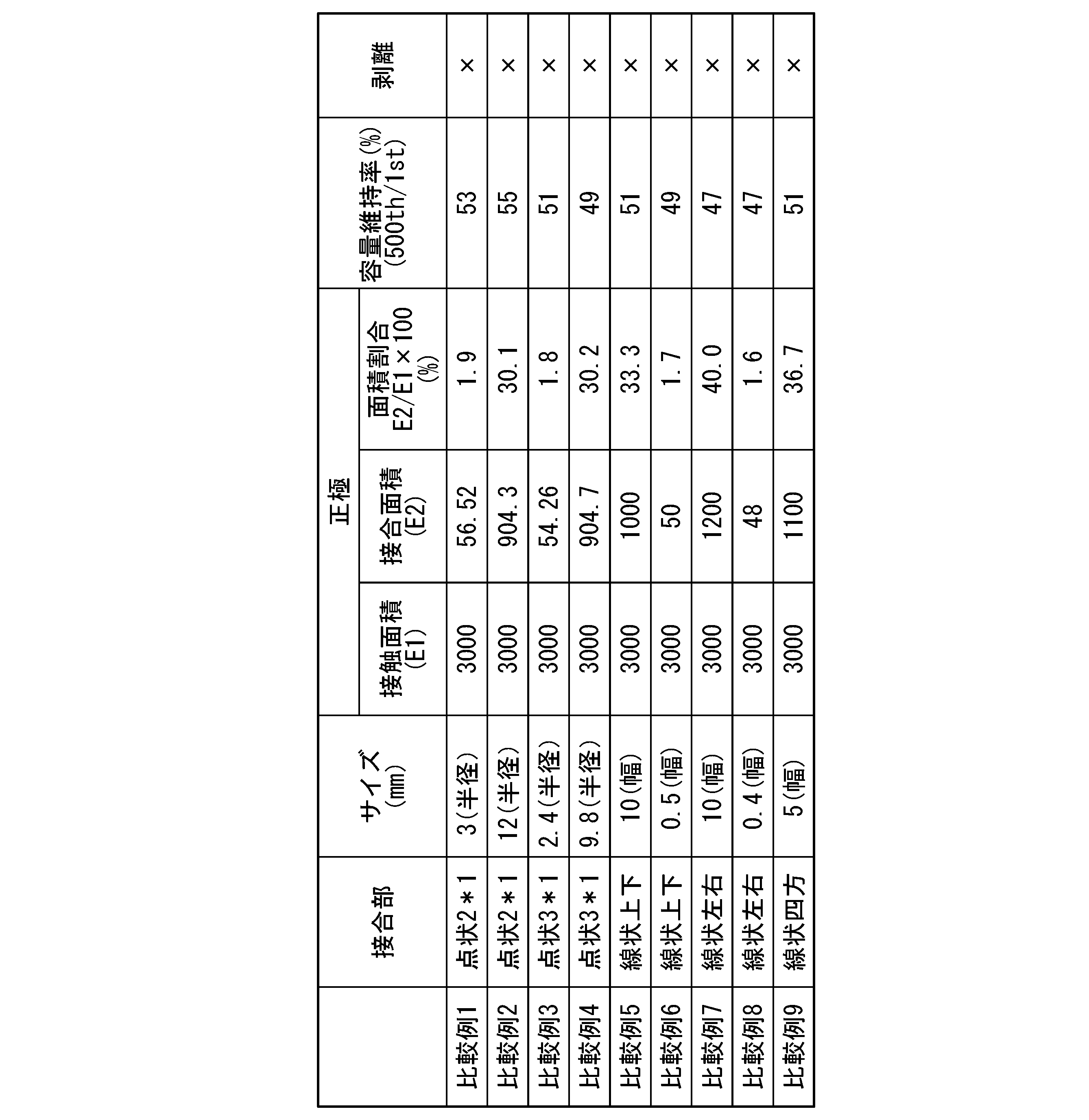
表1及び表2に示すように、実施例1~21の電池は、比較例1~9の電池と比較して、正極において、それぞれの集電体と活物質層との間の接着強度を維持すると共に、容量維持率が高く、優れたサイクル特性を示すことが確認された。
(実施例22)
実施例22では、先ず、厚さ15μmのアルミニウム箔(集電体)の一面に、正極スラリーを塗布した。正極スラリーは、正極活物質と導電助剤とバインダと溶媒とを混合して作製した。
実施例22では、先ず、厚さ15μmのアルミニウム箔(集電体)の一面に、正極スラリーを塗布した。正極スラリーは、正極活物質と導電助剤とバインダと溶媒とを混合して作製した。
正極活物質としては、LiCoO2を用いた。導電助剤としては、アセチレンブラックを用いた。バインダとしては、ポリフッ化ビニリデン(PVDF)を用いた。溶媒としては、N-メチル-2-ピロリドンを用いた。
97質量部の正極活物質と、1質量部の導電助剤と、2質量部のバインダと、70質量部の溶媒とを混合して、正極スラリーを作製した。乾燥後の正極活物質層における正極活物質の担持量は、15mg/cm2とした。正極スラリーから乾燥炉内で溶媒を除去し、正極活物質層を作成した。正極活物質層をロールプレスで加圧し、正極を作製した。
次に、厚さ15μmのPETフィルムの一面に、負極スラリーを塗布した。負極スラリーは、負極活物質とバインダと溶媒とを混合して作製した。
負極活物質としては、Li4Ti5O12を用いた。バインダとしては、エチルセルロースを用いた。溶媒としては、ジヒドロターピネオールを用いた。
93質量部の負極活物質と、7質量部のバインダと、70質量部の溶媒とを混合して、負極スラリーを作製した。乾燥後の負極活物質層における負極活物質の担持量は、18mg/cm2とした。負極スラリーから乾燥炉内で溶媒を除去し、PETフィルム上に負極スラリーの成型体を作製した。PETフィルムから負極スラリーの成型体をジルコニア製セッターに載置し、1000℃で6時間加熱処理して、負極活物質層を作製した。
得られた負極活物質層を厚さ10μmのアルミニウム箔(集電体)の一面に接合部を介して接着することで、負極を作製した。
実施例22では、正極と、負極を変更し、負極において集電体と負極活物質層とを接合部を介して接合したこと以外は、実施例1と同様の方法によりリチウムイオン二次電池を作製した。
実施例22では、負極において、集電体と負極活物質層との接触面積の総和E1は、3000mm2(縦60mm×横50mm)であった。なお、接触面積の総和E1は、集電体と負極活物質層とが平面視で重なる面積とした。
一方、カーボンブラック80質量部とアクリルバインダー20質量部とを混合し、この混合物を用いて、負極において接合部を作製した。接合部は、半径2.5mmの円形点状に形成され、集電体の中央部を通り縦方向に延びる線上に並んで3つの接合部を配置した。この3つの接合部により負極活物質層と集電体との間を接着した。また、複数の接合部による接合面積の総和E2は、58.88mm2であった。
これにより、実施例22では、負極において、集電体と負極活物質層との接触面積の総和E1に対する複数の接合部による接合面積の総和E2の面積割合(E2/E1×100)は、2.0%であった。
正極に関して、集電体と正極活物質層との接触面積の総和E1は、3000mm2(縦60mm×横50mm)であった。集電体と正極活物質層は、接合部により接着されていないため、接合部による接合面積の総和E2は0mm2であり、面積割合(E2/E1×100)は0%であった。
(実施例23~42、比較例10~18)
実施例23~42では、負極において、直線状(線状)の接合部の幅、数、配置を変更し、面積割合(E2/E1×100)を本実施形態の範囲(2~30%)内で変更したこと以外は、実施例22と同様の方法によりリチウムイオン二次電池を作製した。
実施例23~42では、負極において、直線状(線状)の接合部の幅、数、配置を変更し、面積割合(E2/E1×100)を本実施形態の範囲(2~30%)内で変更したこと以外は、実施例22と同様の方法によりリチウムイオン二次電池を作製した。
比較例10~18では、負極において、直線状(線状)の接合部の幅、数、配置を変更し、面積割合(E2/E1×100)を本実施形態の範囲(2~30%)外で変更したこと以外は、実施例22と同様の方法によりリチウムイオン二次電池を作製した。
(500サイクル後の容量維持率の測定)
以下に示す方法により、実施例22~42及び比較例10~18の電池に対して定電流充放電試験を施し、500サイクル後の容量維持率を測定した。
以下に示す方法により、実施例22~42及び比較例10~18の電池に対して定電流充放電試験を施し、500サイクル後の容量維持率を測定した。
充電レート0.1C(25℃で1mA定電流充電を行ったときに10時間で充電終了となる電流値)の定電流充電で、電池電圧が3.0Vとなるまで充電(CC充電)を行い、次いで0.05Cの電流値となるまで充電(CV充電)を行った。次いで放電レート0.1Cの定電流放電で、電池電圧が1.5Vとなるまで放電(CC放電)を行った。
その後、充電レート0.5Cの定電流充電で、電池電圧が3.0Vとなるまで充電(CC充電)を行い、次いで0.05Cの電流値となるまで充電(CV充電)を行った。次いで放電レート0.5Cの定電流放電で、電池電圧が1.5Vとなるまで放電(CC放電)を行った。充放電終了後の放電容量(mAh)を検出し、初回サイクルの放電容量Q1を求めた。
その後、充電レート0.5Cの定電流充電で、電池電圧が3.0Vとなるまで充電(CC充電)を行い、次いで0.05Cの電流値となるまで充電(CV充電)を行った。次いで放電レート0.5Cの定電流放電で、電池電圧が1.5Vとなるまで放電(CC放電)を行った。充放電終了後の放電容量(mAh)を検出し、初回サイクルの放電容量Q1を求めた。
放電容量Q1を求めた電池を、再び充電レート0.5Cの定電流充電で、電池電圧が3.0Vとなるまで充電(CC充電)を行い、次いで0.05Cの電流値となるまで充電(CV充電)を行った。次いで放電レート0.1Cの定電流放電で、電池電圧が1.5Vとなるまで放電(CC放電)を行った。上記充放電を1サイクルとカウントし、500サイクルの充放電を行った。その後、500サイクル充放電終了後の放電後の放電容量(mAh)を検出し、放電容量Q2を求めた。
求めた放電容量Q1、Q2から、以下の式を用いて500サイクル後の容量維持率Qを求めた。
Q(%)=(Q2/Q1)×100
求めた放電容量Q1、Q2から、以下の式を用いて500サイクル後の容量維持率Qを求めた。
Q(%)=(Q2/Q1)×100
(剥離の有無)
500サイクル後の容量維持率を測定した後、実施例22~42及び比較例10~18のリチウムイオン二次電池を解体し、負極において、集電体と活物質層との間における剥離の有無を目視で確認した。その結果をまとめたものを下記表3及び表4に示す。
表において、剥離が目視で確認されなかった場合を“〇”(good)で示し、剥離が目視で確認された場合を“×”(poor)で示した。
500サイクル後の容量維持率を測定した後、実施例22~42及び比較例10~18のリチウムイオン二次電池を解体し、負極において、集電体と活物質層との間における剥離の有無を目視で確認した。その結果をまとめたものを下記表3及び表4に示す。
表において、剥離が目視で確認されなかった場合を“〇”(good)で示し、剥離が目視で確認された場合を“×”(poor)で示した。
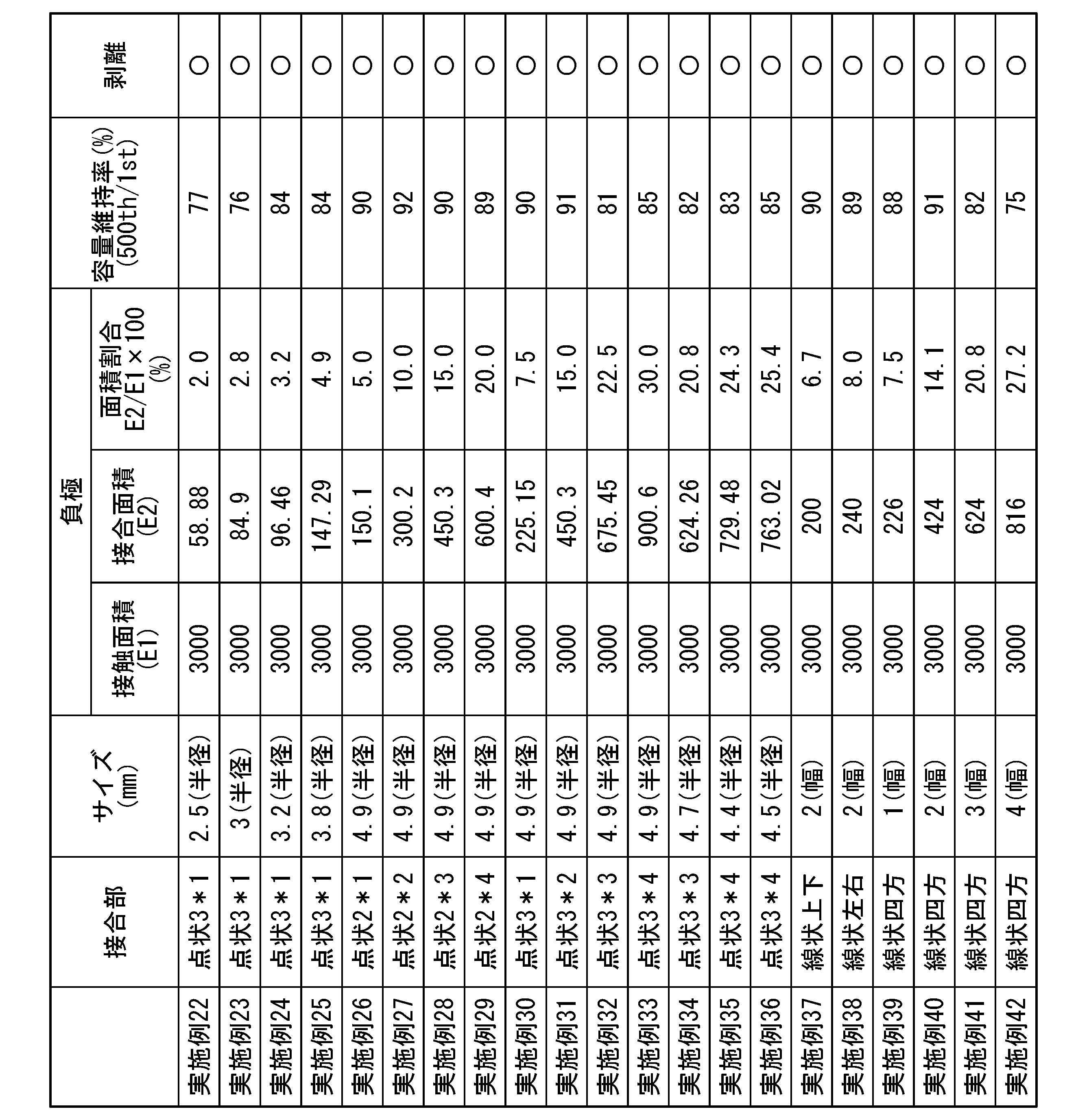
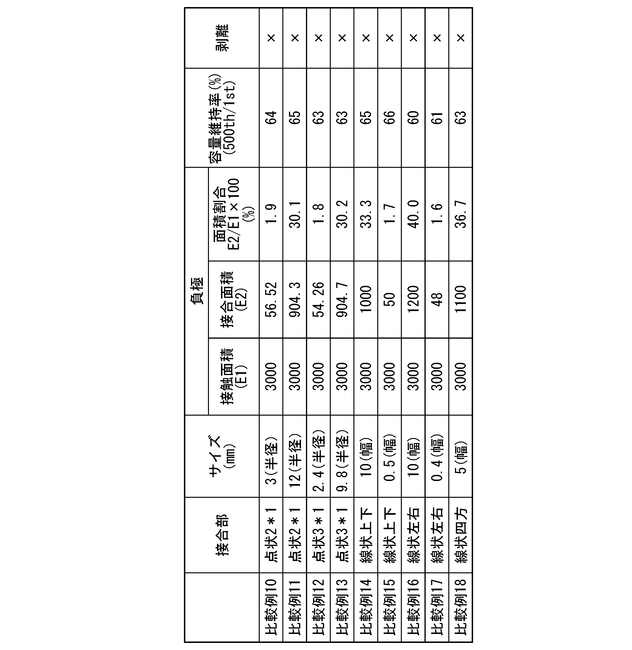
表3及び表4に示すように、実施例22~42の電池は、比較例10~18の電池と比較して、負極において、それぞれの集電体と活物質層との間の接着強度を維持すると共に、容量維持率が高く、優れたサイクル特性を示すことが確認された。
(実施例43)
実施例43では、表1に示す実施例1で作製した正極と、表3に示す実施例22で作製した負極とを組み合わせて用いたこと以外は、実施例1,22と同様の方法によりリチウムイオン二次電池を作製した。
正極の接触面積E1、接合面積E2、及び面積割合(E2/E1×100)は、負極の接触面積E1、接合面積E2、及び面積割合(E2/E1×100)とそれぞれ同一であった。
実施例43では、表1に示す実施例1で作製した正極と、表3に示す実施例22で作製した負極とを組み合わせて用いたこと以外は、実施例1,22と同様の方法によりリチウムイオン二次電池を作製した。
正極の接触面積E1、接合面積E2、及び面積割合(E2/E1×100)は、負極の接触面積E1、接合面積E2、及び面積割合(E2/E1×100)とそれぞれ同一であった。
(実施例44~63、比較例19~27)
実施例44~63及び比較例19~27では、表1及び表2に示す実施例2~21及び比較例1~9で作製した正極と、表3及び表4に示す実施例23~42及び比較例10~18で作製した負極とを順次組み合わせて用いたこと以外は、実施例43と同様の方法によりリチウムイオン二次電池を作製した。
例えば、実施例44では、実施例2の正極と実施例23の負極を組み合わせて用いた。
実施例44~63及び比較例19~27のそれぞれでは、正極の接触面積E1、接合面積E2、及び面積割合(E2/E1×100)は、負極の接触面積E1、接合面積E2、及び面積割合(E2/E1×100)とそれぞれ同一であった。
実施例44~63及び比較例19~27では、表1及び表2に示す実施例2~21及び比較例1~9で作製した正極と、表3及び表4に示す実施例23~42及び比較例10~18で作製した負極とを順次組み合わせて用いたこと以外は、実施例43と同様の方法によりリチウムイオン二次電池を作製した。
例えば、実施例44では、実施例2の正極と実施例23の負極を組み合わせて用いた。
実施例44~63及び比較例19~27のそれぞれでは、正極の接触面積E1、接合面積E2、及び面積割合(E2/E1×100)は、負極の接触面積E1、接合面積E2、及び面積割合(E2/E1×100)とそれぞれ同一であった。
(500サイクル後の容量維持率の測定)
以下に示す方法により、実施例22~63及び比較例10~27の電池に対して定電流充放電試験を施し、500サイクル後の容量維持率を測定した。
以下に示す方法により、実施例22~63及び比較例10~27の電池に対して定電流充放電試験を施し、500サイクル後の容量維持率を測定した。
充電レート0.1C(25℃で1mA定電流充電を行ったときに10時間で充電終了となる電流値)の定電流充電で、電池電圧が3.0Vとなるまで充電(CC充電)を行い、次いで0.05Cの電流値となるまで充電(CV充電)を行った。次いで放電レート0.1Cの定電流放電で、電池電圧が1.5Vとなるまで放電(CC放電)を行った。
その後、充電レート0.5Cの定電流充電で、電池電圧が3.0Vとなるまで充電(CC充電)を行い、次いで0.05Cの電流値となるまで充電(CV充電)を行った。次いで放電レート0.5Cの定電流放電で、電池電圧が1.5Vとなるまで放電(CC放電)を行った。充放電終了後の放電容量(mAh)を検出し、初回サイクルの放電容量Q1を求めた。
その後、充電レート0.5Cの定電流充電で、電池電圧が3.0Vとなるまで充電(CC充電)を行い、次いで0.05Cの電流値となるまで充電(CV充電)を行った。次いで放電レート0.5Cの定電流放電で、電池電圧が1.5Vとなるまで放電(CC放電)を行った。充放電終了後の放電容量(mAh)を検出し、初回サイクルの放電容量Q1を求めた。
放電容量Q1を求めた電池を、再び充電レート0.5Cの定電流充電で、電池電圧が3.0Vとなるまで充電(CC充電)を行い、次いで0.05Cの電流値となるまで充電(CV充電)を行った。次いで放電レート0.1Cの定電流放電で、電池電圧が1.5Vとなるまで放電(CC放電)を行った。上記充放電を1サイクルとカウントし、500サイクルの充放電を行った。その後、500サイクル充放電終了後の放電後の放電容量(mAh)を検出し、放電容量Q2を求めた。
求めた放電容量Q1、Q2から、以下の式を用いて500サイクル後の容量維持率Qを求めた。
Q(%)=(Q2/Q1)×100
求めた放電容量Q1、Q2から、以下の式を用いて500サイクル後の容量維持率Qを求めた。
Q(%)=(Q2/Q1)×100
(剥離の有無)
500サイクル後の容量維持率を測定した後、実施例43~63及び比較例19~27のリチウムイオン二次電池を解体し、正極及び負極において、集電体と活物質層との間における剥離の有無を目視で確認した。その結果をまとめたものを下記表5及び表6に示す。
表において、剥離が目視で確認されなかった場合を“〇”(good)で示し、剥離が目視で確認された場合を“×”(poor)で示した。
500サイクル後の容量維持率を測定した後、実施例43~63及び比較例19~27のリチウムイオン二次電池を解体し、正極及び負極において、集電体と活物質層との間における剥離の有無を目視で確認した。その結果をまとめたものを下記表5及び表6に示す。
表において、剥離が目視で確認されなかった場合を“〇”(good)で示し、剥離が目視で確認された場合を“×”(poor)で示した。

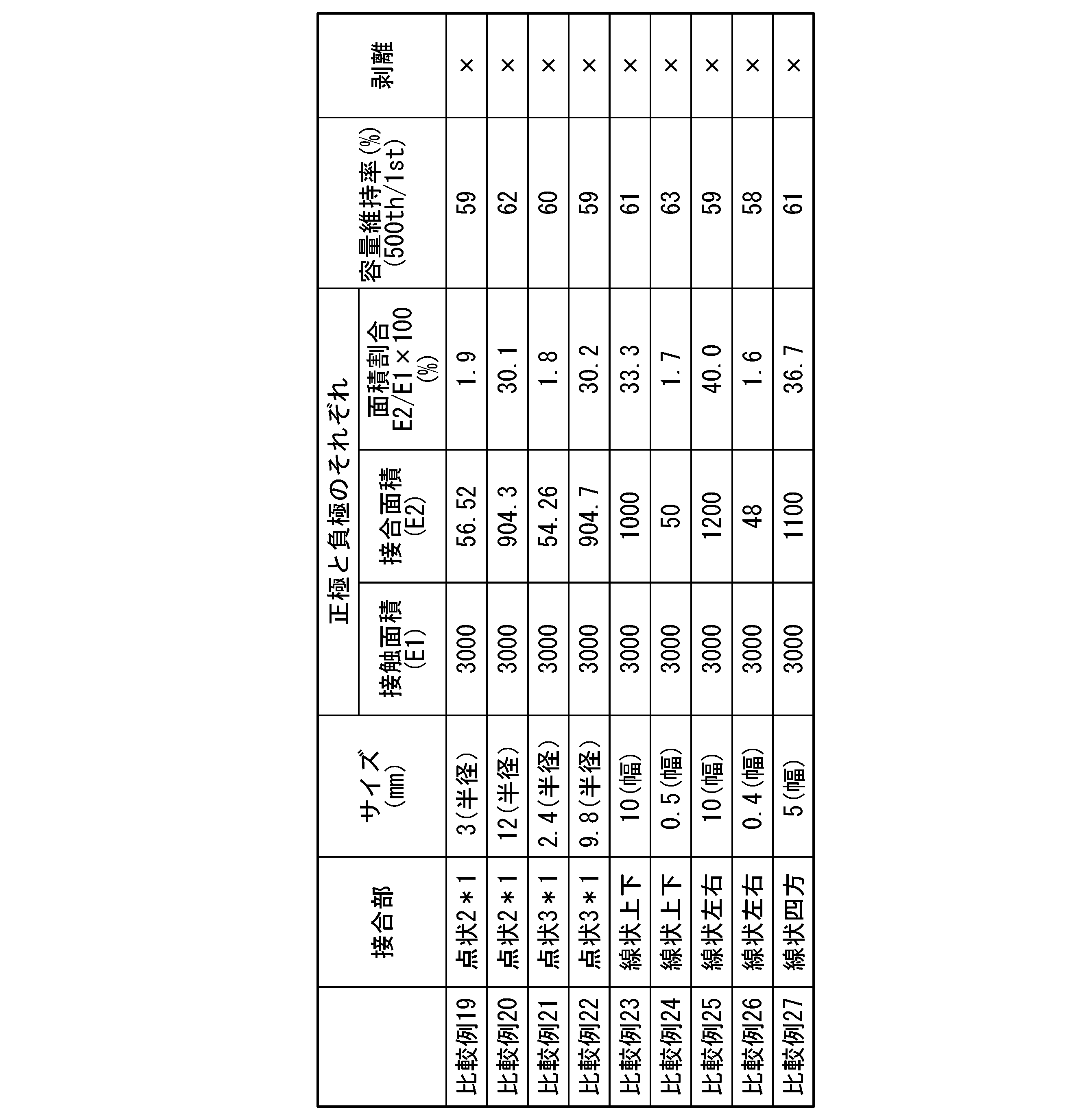
表5及び表6に示すように、実施例43~63の電池は、比較例19~27の電池と比較して、正極及び負極において、それぞれの集電体と活物質層との間の接着強度を維持すると共に、容量維持率が高く、優れたサイクル特性を示すことが確認された。
本実施形態の電極は、リチウムイオン二次電池、ニッケル水素電池などの電池の電極や、電気二重層キャパシタなどのキャパシタの電極として、好適に用いられる。
10…セパレータ、20…正極、22…正極集電体、24…正極活物質層、30…負極、32…負極集電体、34…負極活物質層、40…積層体、50…外装体、52…金属箔、54…樹脂層、60…正極側リード端子、62…負極側リード端子、70…点状の接合部、71…線状の接合部、100A,100B,100C…蓄電素子。
Claims (11)
- 導電性を有するシート状又は板状の集電体と、
前記集電体の少なくとも一面に接触して設けられた板状の活物質層とを備え、
前記活物質層は、前記集電体の面内に設けられた複数の接合部を介して前記集電体の一面と接合されており、
前記活物質層の前記集電体の一面と接触する面積の総和に対する、前記活物質層の前記複数の接合部を介して前記集電体の一面と接合される面積の総和の割合が、2~30%であることを特徴とする電極。 - 前記接合部は、接着材を介して前記活物質層と前記集電体との間を接着していることを特徴とする請求項1に記載の電極。
- 前記複数の接合部は、点状に形成されて、前記集電体の面内に線状に並んで配置されていることを特徴とする請求項1に記載の電極。
- 前記複数の接合部は、点状に形成されて、前記集電体の面内において互いに交差する第1の方向と第2の方向とに格子状又は千鳥状に並んで配置されていることを特徴とする請求項1に記載の電極。
- 前記複数の接合部は、線状に形成されて、前記集電体の周囲に沿って並んで配置されていることを特徴とする請求項1に記載の電極。
- 前記活物質層は、リチウム含有遷移金属酸化物を含むことを特徴とする請求項1に記載の電極。
- 前記リチウム含有遷移金属酸化物は、コバルト酸リチウム、チタン酸リチウムの中から選択される1種であることを特徴とする請求項6に記載の電極。
- 前記活物質層は、焼結板又は圧粉成型体であることを特徴とする請求項1に記載の電極。
- 請求項1~8の何れか一項に記載の電極を備える蓄電素子。
- 前記電極との対極は、炭素材料を主成分とする活物質層を含むことを特徴とする請求項9に記載の蓄電素子。
- 前記蓄電素子が、リチウムイオン二次電池であることを特徴とする請求項9に記載の蓄電素子。
Applications Claiming Priority (2)
| Application Number | Priority Date | Filing Date | Title |
|---|---|---|---|
| JP2023-191345 | 2023-11-09 | ||
| JP2023191345 | 2023-11-09 |
Publications (1)
| Publication Number | Publication Date |
|---|---|
| WO2025100396A1 true WO2025100396A1 (ja) | 2025-05-15 |
Family
ID=95695855
Family Applications (1)
| Application Number | Title | Priority Date | Filing Date |
|---|---|---|---|
| PCT/JP2024/039251 Pending WO2025100396A1 (ja) | 2023-11-09 | 2024-11-05 | 電極及び蓄電素子 |
Country Status (1)
| Country | Link |
|---|---|
| WO (1) | WO2025100396A1 (ja) |
Citations (4)
| Publication number | Priority date | Publication date | Assignee | Title |
|---|---|---|---|---|
| JPH1173947A (ja) * | 1997-08-29 | 1999-03-16 | Ricoh Co Ltd | 電池用電極およびその製造方法 |
| JP2013012393A (ja) * | 2011-06-29 | 2013-01-17 | Hitachi Ltd | リチウムイオン二次電池用電極及びその製造方法、並びにリチウムイオン二次電池及びその製造方法 |
| JP2016100303A (ja) * | 2014-11-26 | 2016-05-30 | トヨタ自動車株式会社 | リチウムイオン二次電池用電極の製造方法 |
| JP2023082849A (ja) * | 2021-12-03 | 2023-06-15 | トヨタ自動車株式会社 | リチウムイオン電池用電極およびその製造方法 |
-
2024
- 2024-11-05 WO PCT/JP2024/039251 patent/WO2025100396A1/ja active Pending
Patent Citations (4)
| Publication number | Priority date | Publication date | Assignee | Title |
|---|---|---|---|---|
| JPH1173947A (ja) * | 1997-08-29 | 1999-03-16 | Ricoh Co Ltd | 電池用電極およびその製造方法 |
| JP2013012393A (ja) * | 2011-06-29 | 2013-01-17 | Hitachi Ltd | リチウムイオン二次電池用電極及びその製造方法、並びにリチウムイオン二次電池及びその製造方法 |
| JP2016100303A (ja) * | 2014-11-26 | 2016-05-30 | トヨタ自動車株式会社 | リチウムイオン二次電池用電極の製造方法 |
| JP2023082849A (ja) * | 2021-12-03 | 2023-06-15 | トヨタ自動車株式会社 | リチウムイオン電池用電極およびその製造方法 |
Similar Documents
| Publication | Publication Date | Title |
|---|---|---|
| JP6726004B2 (ja) | リチウムイオン二次電池 | |
| CN101399371A (zh) | 非水电解质电池及组电池 | |
| CN108292779A (zh) | 锂离子二次电池 | |
| JP2014225326A (ja) | 非水電解質二次電池 | |
| JP7476936B2 (ja) | フィルム外装電池、組電池および前記フィルム外装電池の製造方法 | |
| WO2021192289A1 (ja) | 集電体、蓄電素子及び蓄電モジュール | |
| JP2011159506A (ja) | 非水系二次電池 | |
| CN114792844A (zh) | 用于具有含硅电极的电化学电池的电解质 | |
| JP6656370B2 (ja) | リチウムイオン二次電池および組電池 | |
| WO2017007015A1 (ja) | 非水電解質電池及び電池パック | |
| JP2013131427A (ja) | ラミネート電池 | |
| JP2018120820A (ja) | リチウムイオン二次電池用正極及びリチウムイオン二次電池 | |
| JP2017016905A (ja) | リチウム二次電池の充放電方法 | |
| JP2016072015A (ja) | フレキシブル電池 | |
| JP7003775B2 (ja) | リチウムイオン二次電池 | |
| JP7765220B2 (ja) | 非水電解質二次電池用正極および非水電解質二次電池 | |
| JP7069938B2 (ja) | リチウムイオン二次電池用正極およびこれを用いたリチウムイオン二次電池 | |
| JPWO2020065832A1 (ja) | 導電性物質、正極および二次電池 | |
| JP2014207238A (ja) | 非水電解質電池及び電池パック | |
| JP6102442B2 (ja) | リチウムイオン二次電池 | |
| JP7765221B2 (ja) | 非水電解質二次電池用正極および非水電解質二次電池 | |
| JP2025522651A (ja) | リチウム二次電池 | |
| JP2016207447A (ja) | 非水電解液二次電池 | |
| JP2025513393A (ja) | 円筒型リチウム二次電池 | |
| JP5150095B2 (ja) | 非水電解質電池 |
Legal Events
| Date | Code | Title | Description |
|---|---|---|---|
| 121 | Ep: the epo has been informed by wipo that ep was designated in this application |
Ref document number: 24888691 Country of ref document: EP Kind code of ref document: A1 |