WO2025100252A1 - 積層体 - Google Patents
積層体 Download PDFInfo
- Publication number
- WO2025100252A1 WO2025100252A1 PCT/JP2024/037980 JP2024037980W WO2025100252A1 WO 2025100252 A1 WO2025100252 A1 WO 2025100252A1 JP 2024037980 W JP2024037980 W JP 2024037980W WO 2025100252 A1 WO2025100252 A1 WO 2025100252A1
- Authority
- WO
- WIPO (PCT)
- Prior art keywords
- resin
- layer
- less
- structural unit
- laminate
- Prior art date
- Legal status (The legal status is an assumption and is not a legal conclusion. Google has not performed a legal analysis and makes no representation as to the accuracy of the status listed.)
- Pending
Links
Images

Classifications
-
- B—PERFORMING OPERATIONS; TRANSPORTING
- B32—LAYERED PRODUCTS
- B32B—LAYERED PRODUCTS, i.e. PRODUCTS BUILT-UP OF STRATA OF FLAT OR NON-FLAT, e.g. CELLULAR OR HONEYCOMB, FORM
- B32B15/00—Layered products comprising a layer of metal
- B32B15/04—Layered products comprising a layer of metal comprising metal as the main or only constituent of a layer, which is next to another layer of the same or of a different material
- B32B15/08—Layered products comprising a layer of metal comprising metal as the main or only constituent of a layer, which is next to another layer of the same or of a different material of synthetic resin
- B32B15/088—Layered products comprising a layer of metal comprising metal as the main or only constituent of a layer, which is next to another layer of the same or of a different material of synthetic resin comprising polyamides
-
- C—CHEMISTRY; METALLURGY
- C08—ORGANIC MACROMOLECULAR COMPOUNDS; THEIR PREPARATION OR CHEMICAL WORKING-UP; COMPOSITIONS BASED THEREON
- C08G—MACROMOLECULAR COMPOUNDS OBTAINED OTHERWISE THAN BY REACTIONS ONLY INVOLVING UNSATURATED CARBON-TO-CARBON BONDS
- C08G73/00—Macromolecular compounds obtained by reactions forming a linkage containing nitrogen with or without oxygen or carbon in the main chain of the macromolecule, not provided for in groups C08G12/00 - C08G71/00
- C08G73/06—Polycondensates having nitrogen-containing heterocyclic rings in the main chain of the macromolecule
- C08G73/10—Polyimides; Polyester-imides; Polyamide-imides; Polyamide acids or similar polyimide precursors
-
- H—ELECTRICITY
- H05—ELECTRIC TECHNIQUES NOT OTHERWISE PROVIDED FOR
- H05K—PRINTED CIRCUITS; CASINGS OR CONSTRUCTIONAL DETAILS OF ELECTRIC APPARATUS; MANUFACTURE OF ASSEMBLAGES OF ELECTRICAL COMPONENTS
- H05K1/00—Printed circuits
- H05K1/02—Details
-
- H—ELECTRICITY
- H05—ELECTRIC TECHNIQUES NOT OTHERWISE PROVIDED FOR
- H05K—PRINTED CIRCUITS; CASINGS OR CONSTRUCTIONAL DETAILS OF ELECTRIC APPARATUS; MANUFACTURE OF ASSEMBLAGES OF ELECTRICAL COMPONENTS
- H05K1/00—Printed circuits
- H05K1/02—Details
- H05K1/03—Use of materials for the substrate
Definitions
- the present invention relates to a laminate including a resin film and a metal layer, particularly a laminate that can be used as a substrate material compatible with printed circuit boards and antenna boards for high-frequency bands, and a flexible printed circuit board including the laminate.
- FPCs Flexible printed circuit boards
- FPCs Flexible printed circuit boards
- polyimide resins which have excellent heat resistance, mechanical properties, and electrical insulation properties, have been widely used in FPCs
- metal-clad laminates such as copper-clad laminates (hereinafter sometimes abbreviated as CCL) used in FPCs.
- CCL copper-clad laminates
- 5G fifth-generation mobile communication systems, known as 5G, have come into full swing (see, for example, Patent Document 1), and laminates suitable for high-speed communication applications beyond 5G have been considered.
- Laminates used in FPCs may deform during processing or repeated use, and so they must be resistant to deformation to prevent deterioration of electrical properties due to deformation. However, it is difficult to increase resistance to deformation while controlling the dielectric properties of the laminate within an appropriate range. For this reason, there is a need to develop laminates that are resistant to deformation and can be used for high-speed communication applications beyond 5G.
- the object of the present invention is to provide a laminate having a high 0.2% yield strength (also simply called yield strength), which is an index of strength against plastic deformation, and a flexible printed circuit board including the laminate.
- the present invention includes the following aspects.
- a laminate including a resin film and a metal layer provided on at least one surface of the resin film,
- the surface of the metal layer in contact with the resin film has a minimum autocorrelation length Sal and an aspect ratio Str of surface texture measured by a laser microscope in accordance with ISO25178 under conditions of an observation magnification of 100 times, a cutoff wavelength of 0.375 ⁇ m using an S filter, and no L filter, which satisfy the formula (I): Sal ⁇ Str ⁇ 0.21 (I)
- the laminate according to [1], wherein the surface of the metal layer in contact with the resin film has a level difference Sk of a core portion measured under the above conditions of 0.40 ⁇ m or more.
- the polyimide-based film includes a polyimide-based resin-containing layer (PI-1) and a polyimide-based resin-containing layer (PI-2).
- PI-2 polyimide-based resin-containing layer
- PI-3 polyimide-based resin-containing layer
- At least one of the polyimide-based resin-containing layer (PI-1) and the polyimide-based resin-containing layer (PI-2) contains a polyimide-based resin having a structural unit (A) derived from a tetracarboxylic acid anhydride,
- the structural unit (A) is represented by the formula (A1):
- R a1 each independently represent a halogen atom, or an alkyl group, an alkoxy group, an aryl group, or an aryloxy group which may have a halogen atom;
- k represents an integer of 0 to 2.
- At least one of the polyimide-based resin-containing layer (PI-1) and the polyimide-based resin-containing layer (PI-2) contains a polyimide-based resin having a diamine-derived structural unit (B),
- the structural unit (B) is represented by the formula (B1): In formula (B1), R b1 each independently represent a halogen atom, or an alkyl group, an alkoxy
- the laminate according to any one of items [8] to [12], comprising a structural unit (B1) derived from a diamine represented by the following formula: [14] At least the polyimide-based resin-containing layer (PI-1) contains a polyimide-based resin having a structural unit (A) derived from a tetracarboxylic acid anhydride, and the structural unit (A) is represented by the formula (A3):
- Z represents a divalent organic group
- R a3 each independently represents a halogen atom, or an alkyl group, an alkoxy group, an aryl group, or an aryloxy group which may have a halogen atom;
- Each s independently represents an integer of 0 to 3.
- Z represents a divalent organic group
- R a3 each independently represents a halogen atom, or an alkyl group, an alkoxy group, an aryl group, or an aryloxy group which may have a halogen atom;
- Each s independently represents an integer of 0 to 3.
- A3 derived from an ester bond-containing tetracarboxylic acid anhydride represented by the following formula:
- the present invention can provide a laminate with high durability.
- FIG. 1 is a schematic cross-sectional view showing an example of a layer structure of a laminate of the present invention.
- FIG. 2 is a schematic diagram for explaining a method for measuring a cross-sectional image in the thickness direction of a laminate by a scanning electron microscope.
- 1A to 1C are diagrams for explaining a contour curve before correction, a contour curve after tilt correction, and a contour curve (cross-sectional curve) after tilt correction and average correction in a laminate.
- the laminate of the present invention includes a resin film and a metal layer provided on at least one surface of the resin film.
- the surface of the metal layer in contact with the resin film has a minimum autocorrelation length Sal and an aspect ratio Str of surface texture measured by a laser microscope under conditions of an observation magnification of 100 times, a cutoff wavelength of 0.375 ⁇ m using an S filter, and no L filter in accordance with ISO25178, which satisfy the formula (I): Sal ⁇ Str ⁇ 0.21 (I)
- the minimum autocorrelation length Sal and the aspect ratio Str of the surface texture may be simply written as "Sal" and "Str", respectively, and the same applies to the other roughness parameters described later.
- the minimum autocorrelation length Sal in formula (I) is a numerical representation of the density of the unevenness of the metal surface in units of length, and is one of the spatial parameters of surface roughness. More specifically, Sal represents the periodicity of the surface roughness in the planar direction, and indicates the horizontal distance in the direction in which the autocorrelation function decays to a specific value. The smaller Sal indicates a more abrupt step, and the larger Sal indicates a more gentle shape.
- the aspect ratio Str of the surface texture in formula (I) is a three-dimensional surface texture parameter that quantifies the strength of isotropy or anisotropy of the metal surface, and takes a value of 0 to 1.
- the metal surface When Str is close to 1, the metal surface exhibits strong isotropy, meaning that the unevenness of the surface does not have a regular directionality, that is, there are no streaks or the like on the surface.
- the metal surface When Str is close to 0, the metal surface exhibits strong anisotropy, meaning that the unevenness of the surface has a regular directionality, that is, there are streaks or the like on the surface.
- the inventors of the present invention have conducted research focusing on the interface between the resin film and the metal layer, and have unexpectedly found that when Sal and Str measured under specific conditions on the surface of the metal layer in contact with the resin film satisfy formula (I), the 0.2% yield strength of the laminate is improved.
- formula (I) the 0.2% yield strength of the laminate is improved.
- the reason for this is unclear, but it is thought that in the cross section of the thickness direction of the laminate, the state of stress concentration acting on the resin film and the metal layer differs depending on the unevenness of the interface, and the magnitude of the strain induced at the interface and the internal stress generated differ, and it is also expected that the crystallinity and orientation of the resin layer near the interface will change.
- the metal surface may have surface properties in which gently sloping convex and concave portions exist randomly. Therefore, stress concentration at the interface is unlikely to occur, and it is thought that the crystallinity and/or orientation of the resin layer near the interface in the laminate is increased due to the influence of the surface properties during film formation, and the strength of the laminate as a whole against deformation is improved.
- the metal layer on the resin film may be partially removed by etching or the like.
- the water resistance of the resin film after the metal layer is removed is high from the viewpoint of dielectric properties and drying efficiency during FPC production.
- the inventors have also unexpectedly found that when the surface of the metal layer in contact with the resin film satisfies formula (I), the water resistance and drying speed of the resin film after the metal layer is removed can be improved.
- water resistance refers to the property of being less likely to absorb water when the resin film after the metal layer is removed in the laminate is immersed in pure water, and can be evaluated, for example, by the method described in the Examples.
- drying speed refers to the rate at which pure water decreases when the resin film after the metal layer is removed is hydrated and then heated and dried, and can be evaluated, for example, by the method described in the Examples.
- the water resistance and drying speed of the resin film after the metal layer has been removed can be considered to be properties of the laminate, and are therefore referred to as the water resistance and drying speed of the laminate, respectively.
- the dielectric properties refer to dielectric properties such as Df and Dk
- the increase or improvement of the dielectric properties refers to a decrease in Df and/or Dk.
- the dielectric properties of the laminate can be evaluated by the dielectric properties of the resin film in the laminate.
- the mechanical properties refer to mechanical properties including strength, puncture strength, bending resistance, and elastic modulus
- the increase or improvement of the mechanical properties refers to, for example, an increase in strength, bending resistance, and/or elastic modulus.
- the thermal properties may include CTE, glass transition temperature (hereinafter sometimes referred to as Tg), the degree of thermal denaturation or deterioration, and the increase or improvement of the thermal properties refers to, for example, a decrease in CTE, a increase in Tg, and/or a decrease in thermal denaturation or deterioration.
- Sal x Str in formula (I) is preferably 0.23 ⁇ m or more, more preferably 0.25 ⁇ m or more, even more preferably 0.30 ⁇ m or more, even more preferably 0.40 ⁇ m or more, particularly preferably 0.50 ⁇ m or more, particularly more preferably 1.0 ⁇ m or more, 2.0 ⁇ m or more, 3.0 ⁇ m or more, 5.0 ⁇ m or more, or 7.0 ⁇ m or more, particularly more preferably 8.0 ⁇ m or more, particularly more preferably 8.5 ⁇ m or more, and extremely preferably 9.5 ⁇ m or more.
- Sal x Str in formula (I) is preferably 20 ⁇ m or less, more preferably 17 ⁇ m or less, even more preferably 15 ⁇ m or less, even more preferably 13 ⁇ m or less, particularly preferably 12.0 ⁇ m or less, particularly more preferably 11.5 ⁇ m or less, 11.0 ⁇ m or less, or 10.5 ⁇ m or less.
- Sal ⁇ Str is equal to or greater than the lower limit and/or equal to or less than the upper limit, the uneven structure of the interface in the laminate and the crystallinity and/or orientation of the resin layer are more likely to be in a state that further enhances the effects of the present invention, thereby further improving the strength, water resistance, and drying speed of the laminate.
- the minimum autocorrelation length Sal is not particularly limited as long as it satisfies formula (I), but may be, for example, 0.50 ⁇ m or more, 1.00 ⁇ m or more, 1.30 ⁇ m or more, 1.50 ⁇ m or more, or 2.00 ⁇ m or more, and is preferably 2.2 ⁇ m or more, more preferably 3.0 ⁇ m or more, even more preferably 5.0 ⁇ m or more, even more preferably 7.0 ⁇ m or more, particularly preferably 10.0 ⁇ m or more, particularly more preferably 11.0 ⁇ m or more, and particularly more preferably 11.6 ⁇ m or more.
- Sal in formula (I) may be, for example, 30 ⁇ m or less, 25 ⁇ m or less, or 20 ⁇ m or less, and is preferably 17 ⁇ m or less, more preferably 15 ⁇ m or less, and even more preferably 14.0 ⁇ m or less.
- the strength, water resistance, and drying speed of the laminate can be increased.
- the aspect ratio Str of the surface texture is not particularly limited as long as it satisfies formula (I), but may be, for example, 0.05 or more, preferably 0.07 or more, more preferably 0.10 or more, even more preferably 0.20 or more, even more preferably 0.30 or more, particularly preferably 0.50 or more, especially more preferably 0.60 or more, especially even more preferably 0.81 or more, and is preferably 0.98 or less, more preferably 0.95 or less, and even more preferably 0.90 or less.
- Str in formula (I) is within the above range, the strength, water resistance, and drying speed of the laminate can be increased.
- the surface of the metal layer in contact with the resin film preferably has a core level difference Sk of 0.40 ⁇ m or more measured under the above measurement conditions.
- the core level difference Sk is the maximum height of the core excluding the protruding convex portion and the protruding concave portion minus the minimum height, and represents the variation in the height of the core portion.
- the Sk is more preferably 0.42 ⁇ m or more, even more preferably 0.44 ⁇ m or more, and is preferably 2.0 ⁇ m or less, more preferably 1.0 ⁇ m or less, even more preferably 0.60 ⁇ m or less, even more preferably 0.55 ⁇ m or less, and particularly preferably 0.50 ⁇ m or less.
- the unevenness of the resin film surface tends to make it difficult for water to be absorbed, and the increased crystallinity and/or orientation near the surface of the resin layer (i.e., the interface on the resin film side of the laminate) is advantageous in terms of water resistance and drying speed.
- the surface of the metal layer in contact with the resin film has an absolute value of the difference between the maximum peak height Sp and the maximum valley depth Sv measured under the above measurement conditions (sometimes denoted as
- is preferably 0.001 ⁇ m or more, more preferably 0.005 ⁇ m or more.
- the strength, water resistance, and drying speed of the laminate can be improved. The reason why such an effect is obtained is unclear, but when
- the unevenness of the resin film surface is likely to have an uneven structure that is less likely to absorb water, and the increased crystallinity and/or orientation near the surface of the resin layer (i.e., the interface on the resin film side of the laminate) is advantageous in terms of water resistance and drying speed.
- the maximum peak height Sp is preferably 2.00 ⁇ m or less, more preferably 1.70 ⁇ m or less, even more preferably 1.50 ⁇ m or less, even more preferably 1.20 ⁇ m or less, particularly preferably 1.10 ⁇ m or less or 1.00 ⁇ m or less, especially preferably 0.90 ⁇ m or less, and is preferably 0.10 ⁇ m or more, more preferably 0.30 ⁇ m or more, even more preferably 0.50 ⁇ m or more, even more preferably 0.70 ⁇ m or more.
- Sp is within the above range, the strength, water resistance, and drying speed of the laminate can be increased.
- the maximum valley depth Sv is preferably 1.50 ⁇ m or less, more preferably 1.30 ⁇ m or less, and may be, for example, 1.20 ⁇ m or less, 1.00 ⁇ m or less, or 0.90 ⁇ m or less, and is preferably 0.30 ⁇ m or more, more preferably 0.50 ⁇ m or more, and even more preferably 0.70 ⁇ m or more.
- Sv is within the above range, the strength, water resistance, and drying speed of the laminate can be increased.
- the surface of the metal layer in contact with the resin film may have an expanded area ratio Sdr measured under the above measurement conditions of, for example, 100% or less or 50% or less, preferably 35.0% or less, and more preferably 20% or less.
- the expanded area ratio Sdr indicates how much the expanded area (i.e., surface area) of a defined region has increased relative to the area of the defined region, and specifically indicates the increase in surface area from a completely flat surface when a completely flat surface is taken as 100%.
- the smaller the Sdr the closer the surface shape is to flatness, and the Sdr of a completely flat surface is 0%.
- the larger the Sdr the more uneven the surface shape is.
- the Sdr is more preferably less than 20%, even more preferably 18% or less or 15% or less, even more preferably 13% or less, particularly preferably 10% or less, and particularly preferably 5% or less, and is preferably 0.5% or more, more preferably 1.0% or more, and even more preferably 2% or more.
- the development area ratio Sdr is equal to or less than the upper limit and/or equal to or more than the lower limit, the strength, water resistance, and drying speed of the laminate can be increased. The reason for such an effect is unclear, but when Sdr is within the above range, the metal surface has moderate unevenness, and the surface property can be such that the contact area between the metal surface and the resin is moderate.
- the unevenness is likely to be such that stress concentration at the interface is unlikely to occur, and the crystallinity and/or orientation of the resin layer near the interface in the laminate is increased due to the influence of the surface property during film formation, and the strength against deformation of the entire laminate is improved. Furthermore, it is assumed that the unevenness of the resin film surface is likely to have an uneven structure that is unlikely to absorb water, and the increased crystallinity and/or orientation near the surface of the resin layer (i.e., the interface on the resin film side when laminated) is advantageous in terms of water resistance and drying speed.
- the surface of the metal layer in contact with the resin film has a skewness Sku measured under the above measurement conditions of preferably 3.80 or less, more preferably 3.50 or less, and preferably 1.0 or more, more preferably 1.5 or more, even more preferably 2.0 or more, even more preferably 2.5 or more, particularly preferably 2.8 or more, especially more preferably 3.00 or more, especially even more preferably 3.10 or more, and extremely preferably 3.30 or more.
- Sku is within the above range, the strength, water resistance, and drying speed of the laminate can be increased.
- the skewness Sku obtained by a laser microscope is an index that indicates the sharpness of the height distribution on the surface of the metal layer.
- Sku means kurtosis, a measure of sharpness, and indicates the sharpness (pointedness) of the height distribution.
- Sku>3 it means that there are many sharp convex and concave parts
- Sku ⁇ 3 it means that there are many concave and convex parts with flattened tips and the surface is relatively flat
- the surface of the metal layer in contact with the resin film may have an arithmetic mean height Sa measured under the above measurement conditions of, for example, 0.05 ⁇ m or more or 0.10 ⁇ m or more, preferably 0.14 ⁇ m or more, and may also be, for example, 0.5 ⁇ m or less, 0.4 ⁇ m or less, or 0.3 ⁇ m or less, and is preferably less than 0.25 ⁇ m, more preferably 0.22 ⁇ m or less, even more preferably 0.20 ⁇ m or less, and even more preferably 0.17 ⁇ m or less or 0.16 ⁇ m or less.
- the arithmetic mean height Sa is a parameter that expands the two-dimensional parameter Ra into three dimensions, and represents the average value of the height difference from the average surface.
- the surface of the metal layer in contact with the resin film has a maximum height Sz measured under the above measurement conditions of preferably 3.5 ⁇ m or less, more preferably 3.0 ⁇ m or less, even more preferably 2.8 ⁇ m or less, 2.50 ⁇ m or less or 2.1 ⁇ m or less, even more preferably 2.00 ⁇ m or less, particularly preferably 1.90 ⁇ m or less or 1.80 ⁇ m or less, and is preferably 0.1 ⁇ m or more, more preferably 0.5 ⁇ m or more, even more preferably 1.0 ⁇ m or more, even more preferably 1.3 ⁇ m or more, particularly preferably 1.5 ⁇ m or more.
- Sz is within the above range, the strength, water resistance, and drying speed of the laminate can be increased.
- are collectively referred to as the "surface roughness parameters" of a metal surface.
- the arithmetic mean height Ra of the metal layer on the surface in contact with the resin film is preferably 0.01 to 0.5 ⁇ m, more preferably 0.05 to 0.3 ⁇ m, even more preferably 0.1 to 0.25 ⁇ m, and may be, for example, 0.12 to 0.20 ⁇ m.
- the maximum height Rz is preferably 0.1 to 2 ⁇ m, more preferably 0.5 to 1.6 ⁇ m, and may be, for example, 0.60 to 1.0 ⁇ m.
- the ten-point mean roughness Rzjis is preferably 0.05 to 2 ⁇ m, more preferably 0.1 to 1.5 ⁇ m, even more preferably 0.2 to 1.0 ⁇ m, even more preferably 0.30 to 0.80 ⁇ m, and particularly preferably 0.30 to 0.70 ⁇ m.
- the surface roughness parameters of a metal surface can be measured by observing the surface of the metal layer that contacts the resin film with a laser microscope at a magnification of 100 times to obtain a three-dimensional shape image, and then analyzing the obtained three-dimensional shape image.
- the analysis of Sal, Str, Sk, Sdr, Sp, Sv, Sku, Sa, and Sz can be performed in accordance with ISO 25178 under conditions of a cutoff wavelength of 0.375 ⁇ m using an S filter and no L filter, and the analysis of Ra, Rz, and Rzjis can be performed in accordance with JIS B0601:2013 by analyzing a contour curve obtained at any point in the obtained three-dimensional shape image under conditions of ⁇ s of 2.5 ⁇ m, ⁇ c, and ⁇ f not set.
- the surface roughness parameters of a metal surface can be determined, for example, by the method described in the Examples.
- the metal layer may be manufactured by, for example, electrolytic casting such as electroplating or plastic processing such as rolling, or a commercially available product may be used.
- a surface treatment layer may be provided on at least one surface of the metal foil by electroplating. Examples of the surface treatment layer include a roughened layer, an anti-rust layer, and, if necessary, an alloy layer provided between the surface of the metal foil and the roughened layer, and a chromate layer or a silane coupling agent layer provided on the surface of the anti-rust layer.
- the metal layer is a copper foil, electrolytic copper foil or rolled copper foil can be used, and the metal layer preferably has a roughened layer made of copper, zinc, titanium, tungsten, molybdenum, nickel, cobalt, iron, or two or more of these elements, and/or an anti-rust layer made of zinc, tin, nickel, cobalt, chromium, molybdenum, or two or more of these elements. From the viewpoint of providing a uniform roughening layer, it is preferable to further provide an alloy layer of copper and at least one element selected from molybdenum, zinc, tungsten, nickel, cobalt, and iron on the surface of the copper foil. In this specification, the surface treatment layer is also referred to as the "metal layer".
- the metal layer may be a commercially available product that satisfies the above-mentioned range of surface roughness parameters, or the surface roughness parameter may be adjusted to within the above-mentioned range, for example, by forming a surface treatment layer having a predetermined roughness on the metal surface.
- the thickness of the surface treatment layer is 2.0 ⁇ m or less, preferably 0.2 ⁇ m or more and 1.5 ⁇ m or less, from the viewpoint of easily adjusting the surface roughness parameters of the metal foil surface.
- the laminate of the present invention includes metal layers on both sides of a resin film
- both metal layers may satisfy formula (I) on the surfaces in contact with the resin film.
- each surface roughness parameter may be the same or different on the surface where one metal layer is in contact with the resin film and the surface where the other metal layer is in contact with the resin film.
- the metal layer is provided on at least one surface of the resin film, that is, the metal layer may be provided on only one surface or on both surfaces of the resin film.
- examples of metals constituting the metal layer include aluminum, copper, iron, nickel, chromium, titanium, tantalum, stainless steel, and alloys thereof.
- the metal layer is preferably a copper layer, a copper alloy layer, a SUS layer, an aluminum layer, etc., and from the viewpoints of electrical conductivity and metal workability, a copper layer or a copper alloy layer is more preferable, and a copper layer is particularly preferable.
- the metal layer is preferably a metal foil layer, and a metal foil of each of the above-mentioned metals is more preferable, a copper foil layer or a copper alloy foil layer is even more preferable, and a copper foil layer is particularly preferable.
- the thickness of the metal layer, particularly the copper layer is preferably 1 ⁇ m or more, more preferably 5 ⁇ m or more, and even more preferably 10 ⁇ m or more. From the viewpoint of facilitating miniaturization of the circuit and improving bending resistance, the thickness is preferably 100 ⁇ m or less, more preferably 50 ⁇ m or less, even more preferably 30 ⁇ m or less, and particularly preferably 20 ⁇ m or less.
- the thickness of the metal layer, particularly the copper layer can be measured using a film thickness meter or the like. Note that when the resin film contains metal layers, particularly copper layers, on both sides, the thickness of each metal layer, particularly each copper layer, may be the same or different.
- the laminate of the present invention includes a resin film.
- the resin constituting the resin film is not particularly limited, and examples thereof include thermosetting resins selected from diallyl phthalate resins, silicone resins, phenolic resins, unsaturated polyester resins, polyurethane resins, melamine resins, urea resins, xylene resins, furan resins, aniline resins, acetone-formaldehyde resins, alkyd resins, maleimide resins, maleimide-cyanate ester resins, cyanate ester resins, benzoxazine resins, polybenzimidazole resins, and polycarbodiimide resins; olefin resins; acrylic resins; styrene resins; rubber resins; fluorine resins; vinyl resins; general-purpose engineering plastics; super engineering plastics such as liquid crystal polymers and aromatic polyether resins; polyamide resins; polyimide resins such as polyimide resins and polyamideimide
- the resin film preferably contains at least one resin selected from the group consisting of polyimide-based resins, liquid crystal polymers, fluorine-based resins, aromatic polyether-based resins, epoxy-based resins and maleimide-based resins, more preferably contains a polyimide-based resin and/or a liquid crystal polymer, and even more preferably contains a polyimide-based resin.
- At least one of the resins constituting the resin film preferably has orientation and/or crystallinity.
- the orientation of the resin in the resin film can be confirmed by laser Raman spectroscopy or the like, and the crystallinity can be confirmed by small-angle X-ray scattering, wide-angle X-ray scattering, or IR measurement.
- the weight average molecular weight, the ratio of the weight average molecular weight to the number average molecular weight, the glass transition temperature, and the tensile modulus of elasticity of the resin constituting the resin film are not particularly limited, and can be selected, for example, from the same ranges as those of the polyimide-based resin described below.
- the resin film is preferably a polyimide-based film containing a polyimide-based resin.
- a polyimide-based resin can improve the strength, water resistance, and drying speed of the laminate.
- a polyimide-based film may be referred to as a "PI-based film”
- a polyimide-based resin may be referred to as a "PI-based resin.”
- the resin film may be a single layer film or a laminated film.
- the PI-based film when it is a laminated film, it preferably contains a polyimide-based resin-containing layer (PI-1) and a polyimide-based resin-containing layer (PI-2).
- the PI-based film may contain other PI-based resin-containing layers other than these PI-based resin-containing layers, and may contain other layers other than the PI-based resin-containing layers. Examples of other layers include adhesive layers.
- the PI-based film of the present invention preferably further contains a PI-based resin-containing layer (PI-3) in addition to the PI-based resin-containing layer (PI-1) and the PI-based resin-containing layer (PI-2).
- the PI-based film of the present invention preferably contains the PI-based resin-containing layer (PI-2), the PI-based resin-containing layer (PI-1), and the PI-based resin-containing layer (PI-3) in this order, and more preferably contains them adjacent to each other in this order.
- a PI-based film including the PI-based resin-containing layer (PI-1), the PI-based resin-containing layer (PI-2) and the PI-based resin-containing layer (PI-3) (sometimes referred to as the PI-based resin-containing layers (PI-1) to (PI-3) or layers (PI-1) to (PI-3)) is sometimes referred to as the PI-based film (L).
- the term "PI-based film” includes both single-layer films and laminated films, and when the PI-based resin-containing layer, particularly the PI-based resin-containing layer (PI-1), the PI-based resin-containing layer (PI-2) and/or the PI-based resin-containing layer (PI-3) is mentioned, it relates to a PI-based film in the form of a laminated film.
- the PI-based film 10 in a preferred embodiment of the present invention is composed of three adjacent layers, PI-based resin-containing layer 11, PI-based resin-containing layer 12, and PI-based resin-containing layer 13, which are laminated on a metal layer 14 to form a laminate 15.
- the PI-based resin-containing layer 11 preferably corresponds to layer (PI-2), the PI-based resin-containing layer 12 to layer (PI-1), and the PI-based resin-containing layer 13 to layer (PI-3).
- the PI-based film 10 may also include other PI-based resin-containing layers other than the layers (PI-1), (PI-2), and (PI-3), or other layers other than the PI-based resin-containing layers.
- PI-1 the layers
- PI-2 the layers
- PI-3 the layers
- other layers include adhesive layers formed from polymeric materials such as acrylic resins other than PI-based resins.
- the thickness of the resin film is preferably 20 ⁇ m or more, more preferably 25 ⁇ m or more, even more preferably 30 ⁇ m or more, even more preferably 35 ⁇ m or more, and particularly preferably 40 ⁇ m or more, and is preferably 150 ⁇ m or less, more preferably 130 ⁇ m or less, even more preferably 100 ⁇ m or less, even more preferably 90 ⁇ m or less, especially preferably 80 ⁇ m or less, especially more preferably 70 ⁇ m or less, and especially more preferably 60 ⁇ m or less.
- the laminate can have mechanical properties such as high strength and flexibility suitable for flexible printed circuit boards and the like.
- the strength can be improved while reducing Df, a laminate can be obtained that has a good balance between mechanical properties suitable for flexible printed circuit boards and dielectric properties suitable for high-speed communication applications such as 5G.
- the thickness of the film can be selected from the range of the thickness of the resin film described above, but the thickness of the layer (PI-1) is preferably 10 ⁇ m or more, and the thickness of the layer (PI-2) is preferably 2 ⁇ m or more.
- the thicknesses of the layers (PI-1) and (PI-2) are equal to or more than the lower limit, the strength of the laminate can be further improved.
- the thickness of the layer (PI-1) is more preferably 15 ⁇ m or more, even more preferably 20 ⁇ m or more, even more preferably 30 ⁇ m or more, and is preferably 80 ⁇ m or less, more preferably 60 ⁇ m or less, even more preferably 55 ⁇ m or less, and even more preferably 50 ⁇ m or less.
- the thickness of the layer (PI-2) is more preferably 2.5 ⁇ m or more, even more preferably 3 ⁇ m or more, even more preferably 3.5 ⁇ m or more, and is preferably 20 ⁇ m or less, more preferably 15 ⁇ m or less, even more preferably 10 ⁇ m or less, and even more preferably 8 ⁇ m or less.
- the thickness of layer (PI-3) may be selected from the range of the thickness of layer (PI-2) described above.
- the thicknesses of layers (PI-2) and (PI-3) may be the same or different from each other, but from the viewpoint of suppressing warping of the laminate, it is preferable that one value is within the range of ⁇ 25% of the other value, and more preferably within the range of ⁇ 20%.
- the thickness of each layer can be measured using a laser microscope or the like, for example, by the method described in the Examples.
- the thickness of layer (PI-2) is preferably 0.05 to 0.3 times the thickness of layer (PI-1).
- the laminate can have mechanical properties such as high strength and flexibility suitable for flexible printed circuit boards and the like.
- the strength can be improved while reducing Df, a laminate can be obtained that has a good balance between mechanical properties suitable for flexible printed circuit boards and dielectric properties suitable for high-speed communication applications such as 5G.
- the thickness of layer (PI-2) is more preferably 0.08 times or more, even more preferably 0.10 times or more, particularly preferably 0.12 times or more, and more preferably 0.25 times or less, even more preferably 0.23 times or less, particularly preferably 0.20 times or less, relative to the thickness of layer (PI-1).
- the thickness of layer (PI-3) may be selected from the range of layer (PI-2) above.
- the type of PI resin constituting layers (PI-1) to (PI-3) is not particularly limited, but from the viewpoint of increasing the yield strength while maintaining excellent dielectric properties, it is preferable that layers (PI-1) to (PI-3) each include a non-thermoplastic polyimide resin-containing layer (hereinafter sometimes referred to as an mPI layer) and/or a thermoplastic polyimide resin-containing layer (hereinafter sometimes referred to as a TPI layer).
- mPI layer non-thermoplastic polyimide resin-containing layer
- TPI layer thermoplastic polyimide resin-containing layer
- layers (PI-1) and (PI-2) are preferably mPI layers or TPI layers, respectively, and it is more preferable that one of layers (PI-1) and (PI-2) is an mPI layer and the other is a TPI layer.
- the mPI layer is generally the main PI resin-containing layer in a PI film for flexible printed circuit boards.
- the TPI layer can also function as an adhesive layer that bonds the PI film to a metal layer (e.g., a copper layer), and is preferably located as the outermost layer in the PI film that can come into contact with the metal layer.
- At least one PI resin-containing layer is preferably an mPI layer, and at least one (preferably at least two) PI resin-containing layer is preferably a TPI layer, and more preferably a TPI layer, an mPI layer, and a TPI layer are provided in this order. Therefore, in the PI film (L), the layer (PI-1) is preferably an mPI layer, and the layers (PI-2) and (PI-3) are preferably TPI layers.
- the PI film (L) has such a layer structure, the improved thermal properties are ensured in the mPI layer, thermal denaturation and deterioration are suppressed, and the dimensional stability of the PI film can be ensured, and the TPI layer can increase the adhesion with a metal layer (e.g., a copper layer), and further improve the yield strength of the PI film.
- the PI film (L) contains a plurality of TPI layers or mPI layers, the structures of the TPI layers or mPI layers may be the same or different from each other.
- the structures of the layer (PI-1), the layer (PI-2), and the layer (PI-3) are usually different from each other, but the structures of the layer (PI-2) and the layer (PI-3) may be the same or different from each other.
- the PI-based film when it is a single-layer film, it is composed of one PI-based resin-containing layer, the type of which is not particularly limited, and it is preferable to adopt the configuration of the layer (PI-1) from the viewpoint of increasing the strength while maintaining excellent dielectric properties.
- the thickness of the film can be selected from the range of thicknesses of the resin film described above.
- the PI resin contained in the PI film is a resin containing a repeating structural unit containing an imide group, and may contain a repeating structural unit containing both an imide group and an amide group.
- the "non-thermoplastic" polyimide resin means a polyimide resin having a storage modulus of 1.0 ⁇ 10 9 Pa or more at 40° C. and a storage modulus of 1.0 ⁇ 10 8 Pa or more at 300° C., as measured using a dynamic mechanical analyzer (DMA), and the "thermoplastic" polyimide resin means a polyimide resin having a storage modulus of 1.0 ⁇ 10 9 Pa or more at 40° C. and a storage modulus of less than 1.0 ⁇ 10 8 Pa at 300° C.
- the storage modulus can be measured, for example, by the method described in the Examples.
- the PI resin constituting the PI film preferably contains a tetracarboxylic anhydride-derived structural unit (A) and a diamine-derived structural unit (B).
- structural unit derived from means “structural unit derived from”, for example, "structural unit (A) derived from tetracarboxylic anhydride” means “structural unit (A) derived from tetracarboxylic anhydride”.
- the PI film contains structural unit (A) means “the PI resin constituting the PI film contains structural unit (A)"
- the PI resin-containing layer contains structural unit (A) means “the PI resin constituting the PI resin-containing layer contains structural unit (A)" and the same applies to other structural units.
- the PI resin constituting (or contained in) the PI film can be interpreted as the PI resin constituting (or contained in) at least one layer of the PI resin-containing layer, at least one layer of the layers (PI-1) and (PI-2), or at least one layer of the layers (PI-1) to (PI-3).
- the structural unit (A) derived from a tetracarboxylic acid anhydride is, for example, a structural unit represented by the formula (1): [In formula (1), Y represents a tetravalent organic group] It is preferable that the structural unit is a structural unit derived from a tetracarboxylic acid anhydride represented by the following formula:
- Y's each independently represent a tetravalent organic group, preferably a tetravalent organic group having 4 to 40 carbon atoms, and more preferably a tetravalent organic group having 4 to 40 carbon atoms and a cyclic structure.
- the cyclic structure include an alicyclic ring, an aromatic ring, and a heterocyclic structure.
- the organic group may have a hydrogen atom substituted with a halogen atom, a hydrocarbon group, an alkoxy group, or a halogenated hydrocarbon group, and in that case, the number of carbon atoms in these groups is preferably 1 to 8.
- the PI resin may contain multiple types of Y, and the multiple types of Y may be the same or different from each other.
- Y include groups or structures represented by formulas (31) to (40); groups in which hydrogen atoms in groups represented by formulas (31) to (40) are substituted with methyl groups, ethyl groups, n-propyl groups, isopropyl groups, n-butyl groups, isobutyl groups, sec-butyl groups, tert-butyl groups, fluoro groups, chloro groups, or trifluoromethyl groups; and tetravalent chain hydrocarbon groups having 1 to 8 carbon atoms.
- R a3 each independently represents a halogen atom, or an alkyl group, an alkoxy group, an aryl group, or an aryloxy group which may have a halogen atom; Each s is independently an integer of 0 to 3;
- R a2 each independently represents a halogen atom, or an alkyl group, an alkoxy group, an aryl group, or an aryloxy group which may have a halogen atom;
- Each 1 independently represents an integer from 0 to 3; * represents a bond.
- the PI resin constituting the PI film preferably contains at least one structure selected from the group consisting of structures represented by formulas (31), (32), (33), (39) and (40) as Y in formula (1), more preferably contains at least one structure selected from the group consisting of structures containing a benzene skeleton, and even more preferably contains at least one structure selected from the group consisting of structures represented by formulas (32), (39) and (40).
- R 19 to R 26 and R 23' to R 26' each independently preferably represent a hydrogen atom or an alkyl group having 1 to 6 carbon atoms, more preferably a hydrogen atom or an alkyl group having 1 to 3 carbon atoms, and still more preferably a hydrogen atom.
- e and d each independently preferably represent 0 or 1 (provided that e+d is not 0). Also, e+d preferably represents 1. In formula (31), when e is 0, it indicates that the two benzene rings are not bonded via V1 , and when d is 0, it indicates that the two benzene rings are not bonded via V2 .
- f preferably represents 0 or 1, and more preferably represents 0.
- g and h each independently represent an integer of 0 to 2, and more preferably 0 or 1. Furthermore, g+h each independently represent an integer of 0 to 2. When f is 1 or greater, multiple g's and h's may each independently be the same or different.
- R 27 to R 30 each independently preferably represent a hydrogen atom or an alkyl group having 1 to 3 carbon atoms, more preferably a hydrogen atom.
- i is preferably 1 or 2
- a plurality of Ds and R 27 to R 30 each independently may be the same or different.
- Z preferably represents a divalent organic group having 4 to 40 carbon atoms, more preferably represents a divalent organic group having 4 to 40 carbon atoms and a cyclic structure, further preferably represents a divalent organic group having 4 to 40 carbon atoms and an aromatic ring, and particularly preferably represents a divalent organic group represented by formula (z1), formula (z2), or formula (z3): [In formulae (z1) to (z3), R z11 to R z14 each independently represent a hydrogen atom or a monovalent hydrocarbon group which may have a halogen atom, R z2 each independently represent a monovalent hydrocarbon group which may have a halogen atom, n represents an integer of 1 to 4, j each independently represent an integer of 0 to 3, and * represents a bond] and particularly preferably represents a divalent organic group represented by formula (z1).
- R z11 to R z14 each independently represent preferably a hydrogen atom or an alkyl group which may have a halogen atom, more preferably a hydrogen atom or an alkyl group having 1 to 6 carbon atoms which may have a halogen atom, still more preferably a hydrogen atom or an alkyl group having 1 to 3 carbon atoms which may have a halogen atom, and particularly preferably a hydrogen atom.
- R z11 to R z14 may be a monovalent hydrocarbon group which may have a halogen atom, but it is particularly preferable that R z11 to R z14 are all hydrogen atoms.
- n is preferably an integer of 1 to 3, more preferably 1 or 2, and even more preferably 2.
- R z2 each independently represents preferably an alkyl group which may have a halogen atom, more preferably an alkyl group having 1 to 6 carbon atoms which may have a halogen atom, and further preferably an alkyl group having 1 to 3 carbon atoms which may have a halogen atom.
- j is preferably independently 0 or 1, more preferably 0, and even more preferably all j are 0.
- R a3 preferably each independently represents an alkyl group having 1 to 6 carbon atoms, an alkoxy group having 1 to 6 carbon atoms, or an aryl group having 6 to 12 carbon atoms.
- the hydrogen atoms contained in R a3 may be each independently substituted with a halogen atom, and among these, R a3 each independently represents an alkyl group having preferably 1 to 6 carbon atoms, more preferably an alkyl group having 1 to 3 carbon atoms.
- each s preferably represents, independently of the others, an integer from 0 to 2, more preferably 0 or 1.
- R a2 preferably each independently represents an alkyl group having 1 to 6 carbon atoms, an alkoxy group having 1 to 6 carbon atoms, or an aryl group having 6 to 12 carbon atoms.
- the hydrogen atoms contained in R a2 may be substituted, independently of one another, with a halogen atom.
- R a2 is, independently of one another, preferably an alkyl group having 1 to 6 carbon atoms, more preferably an alkyl group having 1 to 3 carbon atoms.
- each 1 preferably represents, independently of the others, an integer from 0 to 2, more preferably 0 or 1.
- the ratio of the structural units derived from tetracarboxylic anhydrides represented by at least one selected from the group consisting of structures represented by formulas (31) to (33), (39) and (40), particularly the ratio of the structural units derived from tetracarboxylic anhydrides represented by at least one selected from the group consisting of structures represented by formulas (32), (39) and (40), relative to the total amount of structural units (A), is preferably 30 mol% or more, more preferably 50 mol% or more, even more preferably 70 mol% or more, particularly preferably 90 mol% or more, and preferably 100 mol% or less.
- the ratio of the structural units can be measured, for example, by 1H -NMR, or can be calculated from the ratio of the raw materials. The same applies to the calculation of the ratio of the structural units of the PI resin below.
- the "total amount" of the structural units means the amount of the unit when the structural unit is composed of one unit, and means the total amount of the units when the structural unit is composed of two or more units.
- the PI resin contained in the PI film preferably the PI resin contained in at least one of the layers (PI-1) and (PI-2), or at least one of the layers (PI-1) to (PI-3), contains a structural unit (A), and the structural unit (A) is represented by the formula (A1):
- R a1 each independently represent a halogen atom, or an alkyl group, an alkoxy group, an aryl group, or an aryloxy group which may have a halogen atom;
- k represents an integer of 0 to 2.
- a structural unit (A1) (hereinafter, may be simply referred to as structural unit (A1)) derived from a tetracarboxylic acid anhydride represented by the formula (A2): [In formula (A2), R a2 each independently represent a halogen atom, or an alkyl group, alkoxy group, aryl group, or aryloxy group which may have a halogen atom, and each 1 independently represents an integer of 0 to 3.] It is preferable that the copolymer contains a structural unit (A2) derived from a tetracarboxylic acid anhydride represented by the following formula (hereinafter, sometimes simply referred to as structural unit (A2)).
- the PI resin contains the structural unit (A1) and/or the structural unit (A2) as the structural unit (A), the strength, water resistance, drying speed and dielectric properties of the laminate can be improved. In addition, the CTE tends to decrease, and the dimensional stability of the laminate can be improved.
- R a1 and R a2 are preferably each independently an alkyl group having 1 to 6 carbon atoms, an alkoxy group having 1 to 6 carbon atoms, or an aryl group having 6 to 12 carbon atoms.
- alkyl group having 1 to 6 carbon atoms examples include a methyl group, an ethyl group, an n-propyl group, an isopropyl group, an n-butyl group, an isobutyl group, a sec-butyl group, a tert-butyl group, an n-pentyl group, a 2-methylbutyl group, a 3-methylbutyl group, a 2-ethylpropyl group, and an n-hexyl group.
- alkoxy group having 1 to 6 carbon atoms examples include a methoxy group, an ethoxy group, a propyloxy group, an isopropyloxy group, an n-butoxy group, an isobutoxy group, a sec-butoxy group, a tert-butoxy group, a pentyloxy group, a hexyloxy group, and a cyclohexyloxy group.
- aryl group having 6 to 12 carbon atoms include a phenyl group, a tolyl group, a xylyl group, a naphthyl group, and a biphenyl group.
- R a1 and R a2 may be substituted, independently of each other, with halogen atoms, such as fluorine, chlorine, bromine and iodine atoms.
- R a1 and R a2 are, independently of each other, preferably an alkyl group having 1 to 6 carbon atoms, more preferably an alkyl group having 1 to 3 carbon atoms.
- the bonding positions of the two carboxylic acid anhydrides bonded to the benzene ring in formula (A1) are not particularly limited, but from the viewpoint of improving the strength, water resistance, drying speed, dielectric properties, CTE, etc. of the laminate, the bonding positions are preferably 1,2-positions and 4,5-positions, or 1,2-positions and 3,4-positions, and more preferably 1,2-positions and 4,5-positions.
- k is preferably 0 or 1, and more preferably 0.
- each 1 is independently preferably an integer of 0 to 2, more preferably 0 or 1, and even more preferably 0.
- formula (A1) is represented by formula (A1-1):
- the structural unit (A2) is a structural unit represented by the formula (A2-1):
- the structural unit (A2-1) is represented by the formula:
- the content thereof is preferably 10 mol% or more, more preferably 15 mol% or more, even more preferably 20 mol% or more, even more preferably 25 mol% or more, and particularly preferably 30 mol% or more, based on the total amount of the structural unit (A), and is preferably 90 mol% or less, more preferably 85 mol% or less, even more preferably 80 mol% or less, even more preferably 75 mol% or less, and particularly preferably 70 mol% or less.
- the contents of the structural unit (A1) and the structural unit (A2) are each within the above ranges, it is advantageous in improving the strength, water resistance, drying speed, and dielectric properties of the laminate. Furthermore, the CTE tends to decrease, and improved dimensional stability of the laminate can be expected.
- the content ratio (molar ratio, (A1):(A2)) is preferably 10:90 to 90:10, more preferably 15:85 to 80:20, even more preferably 20:80 to 70:30, and even more preferably 25:75 to 65:35.
- the content ratio of the structural unit (A1) to the structural unit (A2) is within the above range, the above-mentioned effects of the present invention that are expected from the PI resin having the structural unit (A1) and/or the structural unit (A2) are more easily obtained, and the effects can be further enhanced.
- the PI resin-containing layer preferably includes any one or more of the following components.
- the PI resin in the layers (PI-1) and (PI-2), or the layers (PI-1) to (PI-3) in the PI film each contains the structural unit (A1);
- the PI resin contains the structural unit (A1) and the structural unit (A2);
- the PI resin-containing layer in the PI film, preferably a TPI layer the PI resin contains the structural unit (A1) and the structural unit (A2), and in at least another PI resin-containing layer, preferably an mPI layer, the PI resin contains the structural unit (A1) and/or the structural unit (A2).
- the PI resin contains the structural unit (A1) and the structural unit (A2), and in at least another PI resin-containing layer, preferably the mPI layer, the PI resin contains the structural unit (A1) but does not substantially contain the structural unit (A2).
- substantially does not contain structural units means that the content of the structural unit is 1% by mass or less, preferably 0.1% by mass or less, more preferably 0.01% by mass or less, and particularly preferably 0.001% by mass or less.
- substantially does not contain structural unit (A2) means that the content of structural unit (A2) is 1% by mass or less, preferably 0.1% by mass or less, more preferably 0.01% by mass or less, and particularly preferably 0.001% by mass or less, relative to the total amount of structural unit (A).
- at least one PI resin-containing layer or “at least one PI resin-containing layer” can be read as "at least one of the PI resin-containing layers (PI-1) and (PI-2), or at least one of the PI resin-containing layers (PI-1) to (PI-3).”
- the resin contained in the PI-based film preferably the PI-based resin contained in at least one of the layers (PI-1) and (PI-2), or at least one of the layers (PI-1) to (PI-3), has a structural unit (A) represented by the formula (A3):
- Z represents a divalent organic group
- R a3 each independently represents a halogen atom, or an alkyl group, an alkoxy group, an aryl group, or an aryloxy group which may have a halogen atom;
- Each s independently represents an integer of 0 to 3.
- the copolymer may contain a structural unit (A3) derived from an ester bond-containing tetracarboxylic acid anhydride represented by the following formula (hereinafter, sometimes simply referred to as structural unit (A3)).
- the PI resin contains the structural unit (A3) as the structural unit (A), this can be advantageous in improving the strength, water resistance, drying speed and dielectric properties of the laminate.
- the CTE tends to decrease, and the dimensional stability of the laminate can be expected to improve.
- a relatively low imidization temperature e.g., 350°C or lower
- the strength and dielectric properties of the resulting laminate can be improved. Therefore, even when a laminate is produced by thermally imidizing a PI resin precursor coating film in a laminate configuration with a metal layer, deterioration of the metal layer surface can be suppressed, and a laminate having high strength and excellent high-frequency properties can be obtained.
- R a3 in formula (A3) examples include the same groups as those exemplified as R a3 in formula (39) above, and preferred embodiments are also the same.
- each s is preferably 0 or 1, and more preferably 0, independently.
- Z in formula (A3) can be a divalent organic group similar to the examples given for Z in formula (39) above, and the preferred embodiments are also the same.
- formula (A3) is preferably a structural unit (A3-1) represented by formula (A3-1) or a structural unit (A3-2) represented by formula (A3-2).
- the PI resin contained in the PI film contains the structural unit (A3-1) and/or the structural unit (A3-2) as the structural unit (A), this can be advantageous in improving the strength, water resistance, drying speed and dielectric properties of the laminate.
- the CTE tends to decrease, and improved dimensional stability of the laminate can be expected.
- the strength and dielectric properties of the resulting laminate can be improved. Therefore, even when a laminate is produced by thermally imidizing a PI resin precursor coating film in a laminate configuration with a metal layer, deterioration of the metal layer surface can be suppressed, and a laminate having high strength and excellent high-frequency properties can be obtained.
- the PI resin contained in the PI film preferably at least one PI resin-containing layer, more preferably at least layer (PI-1), and even more preferably the mPI layer, contains the structural unit (A3) as the structural unit (A), particularly the structural unit (A3-1) and/or the structural unit (A3-2)
- the PI resin is not too rigid and can have a flexible structure with a certain degree of freedom, which makes it easier to form a branched structure by heating during imidization, and the strength of the obtained laminate can be further improved.
- Df can be further reduced, and the CTE is reduced, tending to improve the dimensional stability of the laminate.
- the content thereof is preferably 3 mol% or more, more preferably 5 mol% or more, even more preferably 7 mol% or more, and even more preferably 10 mol% or more, relative to the total amount of the structural unit (A), and may be, for example, 20 mol% or more, 30 mol% or more, or 40 mol% or more.
- the content of the structural unit (A3) is preferably 80 mol% or less, more preferably 70 mol% or less, even more preferably 65 mol% or less, and even more preferably 60 mol% or less.
- the structural unit (A3) when the PI resin contained in the PI film, preferably at least the PI resin-containing layer (PI-1), contains the structural unit (A3), it is preferable that the structural unit (A3) contains 50 mol% or less (0 to 50 mol%) of the structural unit (A3) relative to the total amount of the structural unit (A). That is, in such an embodiment, the structural unit (A) possessed by the PI resin may or may not contain the structural unit (A3), and when it contains the structural unit (A3), it contains it in an amount of 50 mol% or less.
- the content of the structural unit (A3) is more preferably 45 mol% or less, even more preferably 35 mol% or less, even more preferably 25 mol% or less, particularly preferably 15 mol% or less, especially more preferably 5 mol% or less, and especially more preferably 1 mol% or less relative to the total amount of the structural unit (A), and the lower limit may be 0 mol% or more.
- the content of the structural unit (A3), particularly the structural unit (A3-1) and/or the structural unit (A3-2) in the PI resin is equal to or less than the upper limit, the strength, water resistance, drying speed, and dielectric properties of the laminate can be improved. In addition, the CTE tends to decrease, and the dimensional stability of the laminate can be improved.
- the PI-based resin contains the structural unit (A1) and the structural unit (A2), and that in at least another PI-based resin-containing layer, preferably the mPI layer, the PI-based resin contains at least two structural units selected from the structural unit (A1), the structural unit (A2) and the structural unit (A3), preferably the structural unit (A1) and the structural unit (A2) and/or the structural unit (A3).
- the PI resin may contain, as the structural unit (A), a structural unit (A4) (hereinafter, may be simply abbreviated as structural unit (A4)) derived from a tetracarboxylic acid anhydride other than the structural units (A1), (A2), and (A3).
- a structural unit (A4) hereinafter, may be simply abbreviated as structural unit (A4)
- a "structural unit (A4) derived from a tetracarboxylic anhydride other than the structural unit (A1), the structural unit (A2), and the structural unit (A3)” refers to a structural unit derived from a tetracarboxylic anhydride that does not fall under any of the structural units (A1), (A2), and (A3), and when a plurality of structural units (A4) are present, the “content of structural unit (A4)” refers to the total amount of structural units (A4).
- examples of the structural unit (A4) include a structural unit derived from a tetracarboxylic acid anhydride in which Y in formula (1) is represented by formula (31), (33) to (38).
- Y in formula (1) is a structural unit derived from a tetracarboxylic acid anhydride represented by formula (42), (44) to (49) or (53), and more preferably, Y in formula (1) is a structural unit derived from a tetracarboxylic acid anhydride represented by formula (42), (46), (49) or (53).
- the content thereof when the PI resin contains the structural unit (A4), the content thereof may be, for example, 0.01 to 55 mol% or 0.01 to 40 mol% relative to the total amount of the structural unit (A), and is preferably 40 mol% or less, more preferably 35 mol% or less, even more preferably 30 mol% or less, and particularly preferably 25 mol% or less, and is usually 0.01 mol% or more, and preferably 10 mol% or more.
- the PI resin constituting the PI film usually contains a diamine-derived structural unit (B) (hereinafter, sometimes simply abbreviated as structural unit (B)).
- the structural unit (B) is, for example, a structural unit represented by the formula (2): [In formula (2), X represents a divalent organic group] It is preferable that the diamine-derived structural unit is represented by the following formula:
- X represents a divalent organic group, preferably a divalent organic group having 2 to 100 carbon atoms.
- the divalent organic group include a divalent aromatic group and a divalent aliphatic group
- examples of the divalent aliphatic group include a divalent acyclic aliphatic group or a divalent cyclic aliphatic group.
- a divalent cyclic aliphatic group and a divalent aromatic group are preferred, and a divalent aromatic group is more preferred.
- the divalent organic group may have a hydrogen atom in the organic group substituted with a halogen atom, a hydrocarbon group, an alkoxy group, or a halogenated hydrocarbon group, and in that case, the number of carbon atoms in these groups is preferably 1 to 8.
- a divalent aromatic group is a divalent organic group having an aromatic group, and may include an aliphatic group or other substituent as part of its structure.
- a divalent aliphatic group is a divalent organic group that has an aliphatic group, and may contain other substituents as part of its structure, but does not contain an aromatic group.
- the PI resin may contain multiple types of X, which may be the same or different from one another.
- X in formula (2) include groups (structures) represented by formulas (60) to (65); groups in which hydrogen atoms in groups represented by formulas (60) to (65) are substituted with methyl groups, ethyl groups, n-propyl groups, isopropyl groups, n-butyl groups, isobutyl groups, sec-butyl groups, tert-butyl groups, fluoro groups, chloro groups, or trifluoromethyl groups.
- R a and R b each independently represent a halogen atom, or an alkyl group, an alkoxy group, an aryl group, or an aryloxy group which may have a halogen atom, and hydrogen atoms contained in R a and R b each independently may be substituted with a halogen atom;
- W each independently represents a single bond, -O-, -CH 2 -, -CH 2 -CH 2 -, -CH(CH 3 )-, -C(CH 3 ) 2 -, -C(CF 3 ) 2 -, -COO-, -OOC-, -SO-, -SO 2 -, -S-, -CO-, -N(R c )- or -CONH-, where R c represents a hydrogen atom or a monovalent hydrocarbon group having 1 to 12 carbon atoms which may be substituted with a halogen atom;
- ring A represents a cycloalkane ring having 3 to 8 carbon atoms.
- R d represents an alkyl group having 1 to 20 carbon atoms; r represents an integer of 0 or more and (the number of carbon atoms in ring A -2) or less; S1 and S2 each independently represent an integer from 0 to 20;
- * represents a bond.
- X in formula (2) include divalent acyclic aliphatic groups such as linear or branched alkylene groups, such as ethylene, trimethylene, tetramethylene, pentamethylene, hexamethylene, propylene, 1,2-butanediyl, 1,3-butanediyl, 1,12-dodecanediyl, 2-methyl-1,2-propanediyl, and 2-methyl-1,3-propanediyl.
- the hydrogen atoms in the divalent acyclic aliphatic groups may be substituted with halogen atoms, and the carbon atoms may be substituted with heteroatoms, such as oxygen and nitrogen atoms.
- the PI resin in the present invention preferably contains a structure represented by formula (60) or formula (61) as X in formula (2), and more preferably contains a structure represented by formula (60).
- each benzene ring or each cyclohexane ring may be bonded at any of the ortho, meta, or para positions, or the ⁇ , ⁇ , or ⁇ positions, based on -W- or the single bond connecting each benzene ring or each cyclohexane ring, and from the viewpoint of improving the strength, water resistance, drying speed, and dielectric properties of the laminate, they can be bonded preferably at the meta or para positions, or the ⁇ or ⁇ positions, and more preferably at the para or ⁇ positions.
- the amino group directly bonded to the benzene ring and the divalent linking group -W- are at the meta positions, the flexibility of the polyimide molecular chain tends to be improved.
- R a and R b are each independently preferably a halogen atom, or an alkyl group, alkoxy group, or aryl group which may have a halogen atom, more preferably a halogen atom, an alkyl group having 1 to 6 carbon atoms, an alkoxy group having 1 to 6 carbon atoms, or an aryl group having 6 to 12 carbon atoms.
- a halogen atom more preferably a halogen atom, an alkyl group having 1 to 6 carbon atoms, an alkoxy group having 1 to 6 carbon atoms, or an aryl group having 6 to 12 carbon atoms.
- Examples of the alkyl group having 1 to 6 carbon atoms, the alkoxy group having 1 to 6 carbon atoms, and the aryl group having 6 to 12 carbon atoms include those exemplified above.
- the hydrogen atoms contained in R a and R b may each independently be substituted with a halogen atom, and examples of the halogen atom include a fluorine atom, a chlorine atom, a bromine atom, and an iodine atom.
- R a and R b are each independently preferably an alkyl group having 1 to 6 carbon atoms or a fluorinated alkyl group having 1 to 6 carbon atoms, and from the viewpoint of adhesion to a metal layer, etc., more preferably an alkyl group having 1 to 6 carbon atoms not containing fluorine, even more preferably an alkyl group having 1 to 3 carbon atoms not containing fluorine, and particularly preferably a methyl group.
- t' and u are each independently preferably an integer of 0 to 2, more preferably 0 or 1.
- W is preferably, independently of each other, a single bond, -O-, -CH 2 -, -C(CH 3 ) 2 -, -C(CF 3 ) 2 -, -SO 2 -, -S-, -COO-, -OOC- or -CO-, more preferably a single bond, -O-, -CH 2 -, -C(CH 3 ) 2 -, -C(CF 3 ) 2 -, -COO-, -OOC- or -CO-, still more preferably a single bond, -O-, -CH 2 - or -C(CH 3 ) 2 -, and particularly preferably -O- or -C(CH 3 ) 2 -.
- n is preferably an integer of 0 to 3, more preferably 1 to 3.
- n is 2 or more, multiple Ws, R a s , and t's may be the same or different, and the positions of the bonds of each benzene ring relative to -W- may also be the same or different.
- W, n, R a , R b , t', and u in one of formulas (60) and (61) may be independently the same as or different from W, n, R a , R b , t', and u in the other of formulas (60) and (61).
- examples of the cycloalkane ring having 3 to 8 carbon atoms represented by ring A include a cyclopropane ring, a cyclobutane ring, a cyclopentane ring, a cyclohexane ring, a cycloheptane ring, and a cyclooctane ring, and preferably a cycloalkane ring having 4 to 6 carbon atoms.
- the bonds may or may not be adjacent to each other.
- the two bonds may be in the ⁇ -position, ⁇ -position, or ⁇ -position relationship, and preferably in the ⁇ -position or ⁇ -position relationship.
- Rd in formula (62) is preferably an alkyl group having 1 to 10 carbon atoms.
- r in formula (62) is preferably 0 or more and preferably 4 or less.
- S1 and S2 in formula (62) are each independently preferably 0 or more, more preferably 2 or more, and preferably 15 or less.
- the ratio of the diamine-derived structural unit represented by formula (60) and formula (61) as X in formula (2) to the total amount of structural unit (B) is preferably 30 mol% or more, more preferably 50 mol% or more or more than 50 mol%, even more preferably 70 mol% or more, particularly preferably 90 mol% or more, and preferably 100 mol% or less.
- the ratio of the diamine-derived structural unit represented by formula (60) and formula (61) as X in formula (2) is within the above range, the strength, water resistance, drying speed, and dielectric properties of the laminate can be improved. In addition, the CTE tends to decrease, and the dimensional stability of the laminate can be improved.
- the PI resin contained in the PI film preferably the PI resin contained in at least one of the layers (PI-1) and (PI-2), or at least one of the layers (PI-1) to (PI-3), contains a structural unit (B), and the structural unit (B) is represented by the formula (B1):
- R b1 each independently represent a halogen atom, or an alkyl group, an alkoxy group, an aryl group, or an aryloxy group which may have a halogen atom;
- each W independently represents a divalent linking group selected from the group consisting of -O-, -CH 2 -, -CH 2 -CH 2 -, -CH(CH 3 )-, -C(CH 3 ) 2 -, -C(CF 3 ) 2 -, -COO-, -OOC-, -SO-, -SO 2 -, -S-,
- the PI resin contains the structural unit (B1) as the structural unit (B), the strength, water resistance, drying speed and dielectric properties of the laminate can be improved.
- the CTE can be reduced, which is expected to improve the dimensional stability of the laminate and may also contribute to improving adhesion to the metal layer.
- a relatively low imidization temperature e.g., 350°C or lower
- the strength and dielectric properties of the resulting laminate can be improved. Therefore, even when a laminate is produced by thermally imidizing a PI resin precursor coating film in a laminate configuration with a metal layer, deterioration of the metal layer surface can be suppressed, and a laminate having high strength and excellent high-frequency properties can be obtained.
- R b1 in formula (B1) examples include the same groups as those exemplified as R a and R b in formula (60) described above.
- q is preferably an integer of 0 to 2, more preferably 0 or 1, independently of one another.
- m in formula (B1) is preferably an integer of 1 to 3, more preferably 2 or 3, from the viewpoint of improving the strength, water resistance, drying speed, dielectric properties, CTE, etc. of the laminate.
- multiple W, R b2 , and q may be the same or different from one another, and the positions of -W- with respect to -NH 2 of each benzene ring may also be the same or different.
- -W- may be bonded independently to any of the ortho, meta, or para positions, or the ⁇ , ⁇ , or ⁇ positions, based on -NH 2 of each benzene ring, and preferably to the meta or para positions, or the ⁇ or ⁇ positions, more preferably to the para or ⁇ positions.
- the bonding positions of the two Ws may be in an ortho, meta, or para relationship, or in an ⁇ , ⁇ , or ⁇ relationship, and preferably in a meta or para relationship, or in a ⁇ or ⁇ relationship.
- R b1 and q in formulae (B1-1) to (B1-6) are defined the same as R b1 and q in formula (B1)
- W 1 to W 6 each independently represent a divalent linking group selected from the group consisting of -O-, -CH 2 -, -CH 2 -CH 2 -CH(CH 3 )-, -C(CH 3 ) 2 -, -C(CF 3 ) 2 -, -COO-, -OOC-, -SO-, -SO 2 -, -S-, -CO-, -N(R c )- and -CONH-, and R c represents a monovalent hydrocarbon group having 1 to 12 carbon atoms which may be substituted with a hydrogen atom or a halogen atom.
- R b1 and q may be exemplified by the same embodiments as those exemplified for R b1 and q in formula (B1), and preferred embodiments are also the same.
- W 1 to W 6 in formulae (B1-1) to (B1-6) are each independently -O-, -CH 2 -, -CH 2 -CH 2 -, -CH(CH 3 )-, -C(CH 3 ) 2 -, -C(CF 3 ) 2 -, -COO-, -OOC-, -SO 2 -, -S-, -CO- or -CONH-.
- W 1 in formula (B1-1) is preferably -O-, -CH 2 -, -C(CH 3 ) 2 -, -SO 2 -, -S- or -CO-.
- W 2 , W 4 and W 6 in formulae (B1-2), (B1-4) and (B1-6) are each preferably -O-.
- W 3 in formula (B1-3) is preferably —O—, —CH 2 —, —C(CH 3 ) 2 —, —SO 2 —, —CO— or —CONH—
- W 5 in formula (B1-5) is preferably —C(CH 3 ) 2 —, —O—, —SO 2 — or —CO—.
- the PI film in the laminate of the present invention preferably contains, as the structural unit (B), a structural unit derived from a diamine in which m in formula (B1) is 1 or 2, such as the structural unit (B1-1) and/or the structural unit (B1-2).
- a structural unit derived from a diamine in which m is 2 it is preferable to contain, for example, the structural unit (B1-2).
- the strength, water resistance, drying speed, and dielectric properties of the laminate can be improved.
- the CTE tends to decrease, and the dimensional stability of the laminate can be improved.
- the inclusion of these structural units can also contribute to improving the adhesion between the PI film and the metal layer.
- the PI film in the laminate of the present invention preferably contains, as the structural unit (B), a structural unit derived from a diamine in which m is 3 or 4, such as the structural units (B1-3) to (B1-6), and more preferably contains a structural unit derived from a diamine in which m is 3.
- a structural unit derived from a diamine in which m is 3 it is preferable to contain, for example, the structural unit (B1-5).
- the strength, water resistance, drying speed, and dielectric properties of the laminate can be improved.
- the CTE tends to decrease, and the dimensional stability of the laminate can be improved.
- the inclusion of these structural units can also contribute to improving the adhesion between the PI film and the metal layer.
- the structural unit (B1) is preferably the structural unit (B1-2), and the structural unit (B1-2) is more preferably a structural unit represented by formula (B1-2') and/or formula (B1-2'').
- R b1 , W 2 and q in formula (B1-2') and formula (B1-2'') are defined the same as R b1 , W 2 and q in formula (B1-2).
- the constitutional unit represented by formula (B1-2') or formula (B1-2'') is preferably a constitutional unit represented by formula (B1-2'a) or formula (B1-2''a), respectively.
- the structural unit (B) contains the above structural unit, the strength, water resistance, drying speed and dielectric properties of the laminate can be improved.
- the CTE tends to decrease, and the dimensional stability of the laminate can be improved.
- the inclusion of these structural units can also contribute to improving the adhesion between the PI film and the metal layer.
- the structural unit (B1) is preferably the structural unit (B1-5), and the structural unit (B1-5) is more preferably a structural unit represented by formula (B1-5a).
- the structural unit (B) contains the above structural unit, it is advantageous in terms of improving the yield strength and dielectric properties of the laminate and reducing the CTE.
- the content thereof is preferably 3 mol% or more, more preferably 5 mol% or more, even more preferably 7 mol% or more, and even more preferably 10 mol% or more, relative to the total amount of the structural unit (B), and may be, for example, 20 mol% or more, 30 mol% or more, or 40 mol% or more. If the content of the structural unit (B1) is equal to or more than the above lower limit, it is advantageous in improving the strength, water resistance, drying speed, and dielectric properties of the laminate, and reducing the CTE.
- the content of the structural unit (B1) may be, for example, 50 mol% or more, 60 mol% or more, or 70 mol% or more relative to the total amount of the structural unit (B).
- the content of the structural unit (B1) is preferably 99 mol% or less, more preferably 95 mol% or less, and even more preferably 90 mol% or less, relative to the total amount of the structural unit (B).
- the PI resin contained in the PI film preferably the PI resin contained in at least one of the layers (PI-1) and (PI-2), or at least one of the layers (PI-1) to (PI-3), has a structural unit (B) represented by the formula (B2):
- R b2 each independently represents a halogen atom, or an alkyl group, an alkoxy group, an aryl group, or an aryloxy group which may have a halogen atom;
- p represents an integer of 0 to 4.
- the PI resin is not too rigid and can have a flexible structure with a certain degree of freedom, so that a branched structure is easily formed by heating during imidization, and the crystallinity tends to increase, which is advantageous in improving the strength, dielectric properties, water resistance, and drying speed of the laminate, and in reducing the CTE, etc.
- R b2 preferably independently represents a halogen atom, or an alkyl group, alkoxy group, or aryl group which may have a halogen atom, more preferably a halogen atom, an alkyl group having 1 to 6 carbon atoms, an alkoxy group having 1 to 6 carbon atoms, or an aryl group having 6 to 12 carbon atoms.
- a halogen atom more preferably a halogen atom, an alkyl group having 1 to 6 carbon atoms, an alkoxy group having 1 to 6 carbon atoms, or an aryl group having 6 to 12 carbon atoms.
- Examples of the alkyl group having 1 to 6 carbon atoms, the alkoxy group having 1 to 6 carbon atoms, and the aryl group having 6 to 12 carbon atoms include those exemplified above.
- R b2 may be substituted independently with a halogen atom, and examples of the halogen atom include the same as those described above.
- R b2 are preferably independently an alkyl group having 1 to 6 carbon atoms or a fluorinated alkyl group having 1 to 6 carbon atoms, and from the viewpoint of adhesion to a metal layer or the like, more preferably an alkyl group having 1 to 6 carbon atoms which does not contain fluorine, even more preferably an alkyl group having 1 to 3 carbon atoms which does not contain fluorine, and particularly preferably a methyl group.
- p's are each independently preferably an integer of 0 to 2, more preferably 0 or 1.
- the -NH2 group bonded to each benzene ring may be bonded to any of the ortho-, meta-, or para-positions, or the ⁇ -, ⁇ -, or ⁇ -positions, based on the single bond connecting each benzene ring. From the viewpoint of improving the strength, dielectric properties, water resistance, and drying speed of the laminate, and reducing the CTE, it is preferably bonded to the meta- or para-position, or the ⁇ - or ⁇ -position, and more preferably to the para- or ⁇ -position.
- formula (B2) is represented by formula (B2'): It is preferable that the PI resin constituting at least one PI resin-containing layer contains, as the structural unit (B), a PI resin having a structural unit derived from a diamine represented by formula (B2), particularly a PI resin having a structural unit derived from a diamine represented by formula (B2'), so that the PI resin is not too rigid and can have a flexible structure with a certain degree of freedom, so that the branched structure is easily formed by heating during imidization, and the crystallinity tends to increase, which is advantageous in improving the strength, water resistance, drying speed and dielectric properties of the laminate, reducing CTE, etc.
- the above effect can be obtained even at a relatively low imidization temperature (for example, 350 ° C. or less), even if a laminate is produced by thermally imidizing a PI resin precursor coating film in a laminated configuration with a metal layer, deterioration of the metal layer surface can be suppressed, and a laminate having high strength and excellent high-frequency characteristics can be obtained.
- a relatively low imidization temperature for example, 350 ° C. or less
- the content thereof is preferably 1 mol% or more, more preferably 5 mol% or more, and even more preferably 10 mol% or more, relative to the total amount of the structural unit (B), and may be, for example, 20 mol% or more, 30 mol% or more, more than 30 mol%, 40 mol% or more, or 50 mol% or more. If the content of the structural unit (B2) is equal to or more than the above lower limit, it is advantageous in improving the strength, water resistance, drying speed, and dielectric properties of the laminate, reducing the CTE, and the like.
- the structural unit (B1) is preferably 99 mol% or less, more preferably 95 mol% or less, and even more preferably 92 mol% or less, relative to the total amount of the structural unit (B), and may be, for example, 90 mol% or less, 80 mol% or less, 70 mol% or less, or 60 mol% or less.
- the total content thereof is preferably 30 mol% or more, more preferably 40 mol% or more, even more preferably 60 mol% or more, particularly preferably 70 mol% or more, particularly more preferably 80 mol% or more, particularly more preferably 90 mol% or more, particularly more preferably 95 mol% or more, and preferably 100 mol% or less, based on the total amount of the structural unit (B).
- the content ratio (molar ratio, (B1):(B2)) is preferably 99:1 to 1:99, more preferably 95:5 to 5:95, and even more preferably 92:8 to 8:92, and may be, for example, 92:8 to 20:80, or 90:10 to 60:40.
- the content ratio of the structural unit (B1) to the structural unit (B2) is within the above range, the above-mentioned effects of the present invention that are expected from the PI resin having the structural unit (B1) and the structural unit (B2) are easily obtained, and the effects can be further enhanced.
- the PI resin-containing layer constituting the PI film preferably includes any one or more of the following components.
- the PI resin in the layers (PI-1) and (PI-2), or the layers (PI-1) to (PI-3) in the PI film contains at least one of the structural unit (B1) and the structural unit (B2);
- the PI resin in layers (PI-1) and (PI-2), or layers (PI-1) to (PI-3) in the PI film contains the structural unit (B1);
- the PI resin in layers (PI-1) and (PI-2), or layers (PI-1) to (PI-3) contains the structural unit (B1) and the structural unit (B2).
- the PI resin contains the structural unit (B1) and the structural unit (B2).
- the structural unit (B) may contain a structural unit (B3) derived from a diamine other than the structural unit (B1) and the structural unit (B2) (hereinafter, may be abbreviated simply as the structural unit (B3)).
- the structural unit (B3) include a structural unit derived from a diamine in which m in the formula (B1) is 0, and a structural unit derived from a diamine in which X in the formula (2) is represented by the formulas (61) to (64), and among these, a structural unit derived from a diamine in which X in the formula (2) is represented by the formula (74) (structural unit derived from p-phenylenediamine) is preferred.
- "structural unit (B3) derived from a diamine other than the structural unit (B1) and the structural unit (B2)” means a structural unit derived from a diamine different from both the structural unit (B1) and the structural unit (B2).
- the content of the structural unit (B3) is preferably 25 mol % or less, more preferably 20 mol % or less, and even more preferably 10 mol % or less, relative to the total amount of the structural unit (B), and is usually 0.01 mol % or more.
- the polyimide resin contained in the PI resin-containing layer (PI-1) may be the same resin as or a different resin from the PI resin contained in the PI resin-containing layer (PI-2).
- the PI resins contained in each layer are different resins.
- the different resins include not only resins with different types of constituent units, but also resins with different contents (or ratios) of the same type of constituent units.
- the PI-based resin-containing layer (PI-1) and the PI-based resin-containing layer (PI-2) each contain a polyimide-based resin having structural units (A) derived from at least two types of tetracarboxylic acid anhydrides.
- A structural units derived from at least two types of tetracarboxylic acid anhydrides.
- the PI resin in the PI resin-containing layer (PI-1) and the PI resin-containing layer (PI-2), or the PI resin-containing layers (PI-1) to (PI-3), preferably the mPI layer and the TPI layer contains the structural unit (A) as structural unit (A1) and/or the structural unit (A2), and the structural unit (B1) as structural unit (B), preferably the structural unit (B1) and the structural unit (B2).
- the PI resin contained in the PI resin-containing layer (PI-1), preferably the mPI layer, constituting the PI film contains at least two types of structural units (A) selected from structural units (A1), (A2) and (A3) (preferably structural unit (A1) and structural unit (A2) and/or structural unit (A3)) selected from structural units (A), the PI resin contained in the PI resin-containing layer (PI-2), preferably the TPI layer, contains structural units (A) as structural units (A1) and structural unit (A2), and the PI resins constituting the PI resin-containing layer (PI-1) and the PI resin-containing layer (PI-2), preferably the mPI layer and the TPI layer, each contain structural units (B1), preferably structural units (B1) and structural units (B2), as structural units (B).
- the PI-based resin contained in the PI-based resin-containing layer (PI-3) when the PI-based resin-containing layer (PI-3) is further included, the PI-based resin contained in the PI-based resin-containing layer (PI-1), preferably the mPI layer, constituting the PI-based film (L) contains at least two types of structural units (A) selected from structural units (A1), (A2) and (A3) (preferably structural unit (A1) and structural unit (A2) and/or structural unit (A3)) selected from structural units (A), the PI-based resin contained in the PI-based resin-containing layer (PI-2) and the PI-based resin-containing layer (PI-3), preferably the TPI layer, contains structural units (A) as structural units (A1) and structural unit (A2), and the PI-based resin contained in the PI-based resin-containing layers (PI-1) to (PI-3), preferably the mPI layer and the TPI layer, each contains structural units (B1), preferably structural units (B1) and structural units (
- the PI resin in each layer is not too rigid and can have a flexible structure with a certain degree of freedom, which makes it easier to form a branched structure by heating during imidization and also tends to increase crystallinity. Furthermore, the interaction between two adjacent layers can be increased. Therefore, the above-mentioned effects of the present invention that are expected from the PI resin having each structural unit can be easily obtained, and the effects can be further enhanced.
- the PI resin constituting the layer (PI-1) contains, as the structural unit (A), the structural unit (A1) and/or the structural unit (A2), and preferably contains at least two structural units selected from the structural unit (A1), the structural unit (A2) and the structural unit (A3), and more preferably contains the structural unit (A1) and the structural unit (A2) and/or the structural unit (A3).
- the content of the structural unit (A1) is preferably 20 mol% or more, more preferably 30 mol% or more, even more preferably 35 mol% or more, particularly preferably 40 mol% or more, and is preferably 80 mol% or less, more preferably 75 mol% or less, even more preferably 70 mol% or less, and particularly preferably 65 mol% or less, based on the total amount of the structural units (A).
- the content of the structural unit (A2) is preferably 20 mol% or more, more preferably 30 mol% or more, even more preferably 35 mol% or more, particularly preferably 40 mol% or more, and preferably 80 mol% or less, more preferably 75 mol% or less, even more preferably 70 mol% or less, and particularly preferably 65 mol% or less, based on the total amount of the structural unit (A).
- the content of the structural unit (A3) is preferably 3 mol% or more, more preferably 5 mol% or more, even more preferably 7 mol% or more, and even more preferably 10 mol% or more, based on the total amount of the structural unit (A).
- the content of the structural unit (A3) is preferably 50 mol% or less, more preferably 45 mol% or less, even more preferably 35 mol% or less, still more preferably 25 mol% or less, particularly preferably 15 mol% or less, particularly preferably 5 mol% or less, and particularly more preferably 1 mol% or less, and the lower limit may be 0 mol%.
- the PI resin is not too rigid and can have a flexible structure with a certain degree of freedom, so that the PI resin is likely to form a branched structure by heating during imidization and has a tendency to increase crystallinity. Therefore, a laminate having excellent strength, dielectric properties and thermal properties can be obtained. Furthermore, the laminate can have excellent water resistance and drying speed.
- the content of the structural unit (A2) in the PI resin constituting the layer (PI-1) is preferably less than 30 mol%, more preferably 25 mol% or less, even more preferably 20 mol% or less, and particularly preferably 10 mol% or less, relative to the total amount of the structural unit (A).
- the layer (PI-1) may be substantially free of the structural unit (A2), and the lower limit of the content of the structural unit (A2) may be 0 mol%.
- the PI resin constituting the layer (PI-1) preferably contains the structural unit (B1) as the structural unit (B).
- the structural unit (B1) preferably contains the structural unit (B1-2) and the structural unit (B1-5), more preferably contains the structural unit (B1-2), and even more preferably contains (B1-2'').
- the content of the structural unit (B1) in the PI resin constituting the layer (PI-1) is preferably 3 mol% or more, more preferably 5 mol% or more, even more preferably 7 mol% or more, and even more preferably 10 mol% or more, relative to the total amount of the structural units (B), and may be, for example, 20 mol% or more, 30 mol% or more, or 40 mol% or more, and is also preferably 80 mol% or less, more preferably 75 mol% or less, even more preferably 70 mol% or less, and particularly preferably 65 mol% or less.
- the PI resin constituting the layer (PI-1) preferably further contains a structural unit (B2) as the structural unit (B), and the content thereof, relative to the total amount of the structural unit (B), is preferably 10 mol % or more, more preferably 20 mol % or more, even more preferably 30 mol % or more or more than 30 mol %, even more preferably 35 mol % or more, and particularly preferably 40 mol % or more, and is preferably 99 mol % or less, more preferably 95 mol % or less, and even more preferably 92 mol % or less, and may be, for example, 90 mol % or less, 80 mol % or less, 70 mol % or less, or 60 mol % or less.
- the PI resin is not too rigid and can have a flexible structure with a certain degree of freedom, so that the PI resin is likely to form a branched structure by heating during imidization and also tends to have high crystallinity.
- This makes it possible to improve the mechanical properties of the layer (PI-1) and reduce Df, and furthermore, to effectively reduce CTE, so that a laminate having excellent strength, dielectric properties, and thermal properties can be obtained.
- the laminate can have excellent water resistance and drying speed.
- the PI-based film includes a layer (PI-2) and may further include a layer (PI-3).
- the PI-based resins constituting the layers (PI-2) and (PI-3) each include the structural unit (A1) as the structural unit (A), and preferably include the structural unit (A1) and the structural unit (A2).
- the content of the structural unit (A1) is preferably 10 mol% or more, more preferably 15 mol% or more, and even more preferably 20 mol% or more, and is preferably 80 mol% or less, more preferably 70 mol% or less, and even more preferably 60 mol% or less, based on the total amount of the structural units (A).
- the content of the structural unit (A2), relative to the total amount of the structural units (A), is preferably 20 mol% or more, more preferably 30 mol% or more, even more preferably 40 mol% or more, even more preferably 50 mol% or more, and particularly preferably 60 mol% or more, and is preferably 90 mol% or less, more preferably 85 mol% or less, even more preferably 80 mol% or less, and even more preferably 75 mol% or less.
- the PI resin is not too rigid and can have a flexible structure with a certain degree of freedom, so that the PI resin is likely to form a branched structure by heating during imidization, and also tends to increase crystallinity.
- This makes it possible to improve the mechanical properties of the layer (PI-2) and the layer (PI-3) and reduce Df, and furthermore, the CTE can be effectively reduced, so that a laminate having excellent strength, dielectric properties, and thermal properties can be obtained.
- the effect of improving the adhesion between the PI film and the metal layer can be expected.
- the laminate can have excellent water resistance and drying speed.
- the content of the structural unit (A3) in the PI resin constituting the layers (PI-2) and (PI-3) is preferably 10 mol % or less, more preferably 8 mol % or less, even more preferably 5 mol % or less, and particularly preferably 3 mol % or less, based on the total amount of the structural unit (A).
- the layers (PI-2) and (PI-3) may be substantially free of the structural unit (A3), and the lower limit of the content of the structural unit (A3) may be 0 mol %.
- the PI resin constituting the layer (PI-2) and the layer (PI-3) preferably contains the structural unit (B1) as the structural unit (B).
- the structural unit (B1) preferably contains the structural unit (B1-2), and more preferably contains the structural unit (B1-2') that enhances the flexibility of the PI resin.
- the content of the structural unit (B1) in the PI resin constituting these layers is preferably 20 mol% or more, more preferably 30 mol% or more, even more preferably 35 mol% or more, particularly preferably 40 mol% or more, and is preferably 99 mol% or less, more preferably 95 mol% or less, and even more preferably 92 mol% or less, for example, 90 mol% or less, 80 mol% or less, 70 mol% or less, or 60 mol% or less, based on the total amount of the structural unit (B).
- the structural unit (B) further includes a structural unit (B2), and the content thereof is preferably 1 mol% or more, more preferably 5 mol% or more, and even more preferably 10 mol% or more.
- the content thereof may be 20 mol% or more, 30 mol% or more, more than 30 mol%, or 40 mol% or more, and is preferably 80 mol% or less, more preferably 70 mol% or less, even more preferably 65 mol% or less, and particularly preferably 60 mol% or less.
- the PI resin constituting the layer (PI-2) and the layer (PI-3)
- the PI resin when the content of the structural unit (B1) and/or the structural unit (B2) is within the above range, the PI resin is not too rigid and can have a flexible structure with a certain degree of freedom, so that the PI resin is likely to form a branched structure by heating during imidization, and also tends to increase crystallinity.
- This makes it possible to improve the mechanical properties of the layer (PI-2) and the layer (PI-3) and reduce Df, and the CTE can also be effectively reduced, so that a laminate having even better strength, dielectric properties and thermal properties can be obtained.
- the effect of improving the adhesion between the PI film and the metal layer can be expected.
- the laminate can have excellent water resistance and drying speed.
- the various physical properties (molecular weight, glass transition temperature, etc.) of the PI resin containing the above-mentioned structural unit (A) and/or structural unit (B) may be appropriately determined based on, for example, the following suitable ranges depending on the role and application of each PI resin-containing layer in the PI film.
- the PI resin constituting the PI film may contain a halogen atom, preferably a fluorine atom, which can be introduced by, for example, the above-mentioned halogen atom-containing substituent.
- a fluorine atom When the PI resin contains a fluorine atom, the relative dielectric constant of the obtained PI film is easily reduced, leading to improvement of the dielectric properties of the laminate.
- fluorine-containing substituents that are preferable for containing fluorine atoms in the PI resin include a fluoro group and a trifluoromethyl group.
- the PI resin preferably does not contain fluorine atoms from the viewpoint of increasing the adhesion of the PI film to the metal layer.
- the PI resin constituting the PI resin-containing layer in contact with the metal layer, preferably the TPI layer, particularly the layer (PI-2) and layer (PI-3) in the PI film preferably does not contain fluorine atoms.
- the PI resin contains fluorine, it tends to weaken the interaction between molecular chains, so when the PI resin does not contain fluorine atoms, the Df of the PI film tends to be reduced.
- the content of halogen atoms, particularly fluorine atoms, in the PI resin is preferably 0.1 to 35 mass%, more preferably 0.1 to 30 mass%, even more preferably 0.1 to 20 mass%, and particularly preferably 0.1 to 10 mass%, based on the mass of the PI resin. If the content of halogen atoms is equal to or greater than the lower limit, the heat resistance and dielectric properties of the resulting PI film are likely to be improved, leading to improved dielectric properties and thermal properties of the laminate. If the content of halogen atoms is equal to or less than the upper limit, it is advantageous in terms of cost, the CTE is easily reduced, and the synthesis of the PI resin is made easier.
- the imidization rate of the PI resin is preferably 90% or more, more preferably 93% or more, and even more preferably 95% or more, and is usually 100% or less. From the viewpoint of improving the strength, water resistance, drying speed, dielectric properties, and thermal properties of the laminate, it is preferable that the imidization rate is equal to or higher than the lower limit.
- the imidization rate indicates the ratio of the molar amount of imide bonds in the PI resin to twice the molar amount of the constituent units derived from tetracarboxylic acid compounds in the PI resin.
- the PI resin contains a tricarboxylic acid compound
- the imidization rate can be determined by IR method, NMR method, etc.
- the polystyrene-equivalent weight average molecular weight (Mw) of the PI resin is preferably 5,000 or more, more preferably 10,000 or more, even more preferably 15,000 or more, and particularly preferably 20,000 or more, from the viewpoint of increasing the strength of the laminate. Also, from the viewpoint of ease of production of the varnish and film-forming properties, it is preferably 1,200,000 or less, more preferably 1,000,000 or less, even more preferably 800,000 or less, and particularly preferably 700,000 or less.
- the Mw of the mPI layer, particularly the layer (PI-1) in the PI film is preferably 5,000 to 800,000, more preferably 10,000 to 700,000.
- the Mw of the TPI layer, particularly the layers (PI-2) and (PI-3) in the PI film is preferably 10,000 to 1,000,000, and more preferably 20,000 to 900,000, respectively.
- the ratio (Mw/Mn) of the weight average molecular weight (Mw) to the number average molecular weight (Mn) of the PI resin is preferably 1.1 or more, more preferably 1.3 or more, even more preferably 1.5 or more, and particularly preferably 1.7 or more, from the viewpoint of the strength of the laminate and the adhesion between the PI film and the metal layer, and is preferably 15 or less, more preferably 12 or less, even more preferably 11 or less, and particularly preferably 10 or less.
- the Mw/Mn of the mPI layer, particularly the layer (PI-1) in the PI film is preferably 1.1 to 15, more preferably 1.5 to 10.
- the Mw/Mn of the TPI layer is preferably 1.1 to 15, more preferably 1.5 to 10.
- Mw and Mn can be determined by gel permeation chromatography (hereinafter sometimes referred to as GPC) measurement and standard polystyrene conversion.
- the Tg of the PI resin is preferably 350°C or less, more preferably 330°C or less, even more preferably 310°C or less, and particularly preferably 300°C or less, from the viewpoint of improving the strength of the laminate and reducing Df.
- the Tg of the PI resin is preferably 200°C or more, more preferably 205°C or more, even more preferably 210°C or more, and particularly preferably 220°C or more, from the viewpoint of improving the strength of the laminate, reducing Df, and improving thermal properties.
- the Tg of the PI resin constituting the mPI layer is preferably 350°C or less, more preferably 330°C or less, even more preferably 310°C or less, and particularly preferably 295°C or less, and is preferably 220°C or more, more preferably 230°C or more, even more preferably 250°C or more, even more preferably 260°C or more, and particularly preferably 270°C or more.
- the Tg of the PI resin constituting the mPI layer is within the above range, the strength of the laminate can be increased, and the dielectric properties and thermal properties can be improved.
- the Tg of the PI resin constituting the TPI layer is preferably 310°C or less, more preferably 300°C or less, even more preferably 290°C or less, even more preferably 270°C or less, particularly preferably 250°C or less, and preferably 200°C or more, more preferably 210°C or more, even more preferably 220°C or more, particularly preferably 230°C or more.
- the Tg of the PI resin can be measured by dynamic viscoelasticity measurement. For example, it can be calculated based on the peak of the tan ⁇ curve, which is the ratio of the storage modulus (E') to the loss modulus (E") obtained using a dynamic viscoelasticity measuring device.
- each PI resin tends to form a preferred higher-order structure with suppressed rotational motion.
- each PI resin-containing layer can be formed by a PI resin having a higher-order structure with maintained orientation, which is thought to contribute to improving the strength against deformation of the resulting laminate.
- the PI resin contained in the PI film in the laminate preferably the PI resin contained in the polyimide resin-containing layer (PI-1), the PI resin contained in the polyimide resin-containing layer (PI-2), and the PI resin contained in the polyimide resin-containing layer (PI-3) each preferably have a storage modulus of 1.0 ⁇ 10 9 Pa or more at 40 ° C.
- the storage modulus of the PI resin is within the above range, the strength of the laminate is easily increased. The reason for this is not clear, but it is thought that the PI resin is likely to have crystallinity and orientation that tend to improve strength due to the influence of the unevenness of the interface between the PI film and the metal layer, and thus tends to improve strength.
- the suitable range of the storage modulus at 40 ° C. of the polyimide resin contained in the layer (PI-1), layer (PI-2), and layer (PI-3) can be appropriately selected from the ranges E'1, E'2, and E'3 described below, respectively.
- the PI-based film comprises a PI-based film having a structure represented by the formulas (X) and (Y): 0.8 ⁇ E'1/E'2 ⁇ 4.5 (X) 0.8 ⁇ E'1/E'3 ⁇ 4.5 (Y)
- E'1 represents the storage modulus at 40°C of the PI resin contained in the PI resin-containing layer (PI-1)
- E'2 represents the storage modulus at 40°C of the PI resin contained in the PI resin-containing layer (PI-2)
- E'3 represents the storage modulus at 40°C of the PI resin contained in the PI resin-containing layer (PI-3)
- the laminated film of the present invention satisfies the formula (X) and the formula (Y), the strength of the laminated body is easily increased. Although the reason for this is unclear, it is believed that the force applied to the laminated body, particularly in the thickness direction, is easily alleviated. Furthermore, the water resistance and drying speed of the laminated body are also easily increased.
- E'1/E'2 in formula (X) and E'1/E'3 in formula (Y) are each preferably 0.90 or more, more preferably 0.95 or more, even more preferably 0.98 or more, particularly preferably 1.00 or more, and preferably 4.00 or less, more preferably 3.50 or less, even more preferably 3.00 or less, even more preferably 2.50 or less, particularly preferably 2.00 or less, particularly preferably 1.50 or less.
- E'1/E'2 and E'1/E'3 are within the above ranges, the strength, water resistance, and drying speed of the laminate are easily improved. Note that E'1/E'2 and E'1/E'3 may be the same value or different values.
- E'1 in formula (X) and formula (Y) is not limited, but is preferably 1.0 x 10 9 Pa or more, more preferably 1.5 x 10 9 Pa or more, even more preferably 2.0 x 10 9 Pa or more, and is preferably 1.0 x 10 11 Pa or less, more preferably 5.0 x 10 10 Pa or less, even more preferably 1.0 x 10 10 Pa or less, still more preferably 8.0 x 10 9 Pa or less, particularly preferably 5.0 x 10 9 Pa or less or 3.5 x 10 9 Pa or less.
- E'2 in formula (X) and E'3 in formula (Y) are not limited, but are each preferably 1.0 ⁇ 10 9 Pa or more, more preferably 1.5 ⁇ 10 9 Pa or more, and even more preferably 2.0 ⁇ 10 9 Pa or more, and preferably 5.0 ⁇ 10 10 Pa or less, more preferably 1.0 ⁇ 10 10 Pa or less, even more preferably 8.0 ⁇ 10 9 Pa or less, and even more preferably 5.0 ⁇ 10 9 Pa or less or 3.5 ⁇ 10 9 Pa or less.
- E'2 and/or E'3 are in the above range, the yield strength, water resistance, and drying speed of the laminate are easily improved. Note that E'2 and E'3 may be the same value or different values.
- the PI resin contained in the PI film in the laminate may each have a storage modulus at 300° C. of 1.0 ⁇ 10 8 Pa or more, or less than 1.0 ⁇ 10 8 Pa. From the viewpoint of increasing the yield strength of the laminate, the storage modulus at 300° C.
- E′1a of the PI resin contained in the PI resin-containing layer (PI-1) (sometimes referred to as E′1a) is not limited, but is preferably 1.0 ⁇ 10 8 Pa or more, more preferably 1.5 ⁇ 10 8 Pa or more, even more preferably 2.0 ⁇ 10 8 Pa or more, and may be, for example, 2.5 ⁇ 10 8 Pa or more.
- E'1a is preferably 1.0 x 10 10 Pa or less, more preferably 5.0 x 10 9 Pa or less, even more preferably 1.0 x 10 9 Pa or less, still more preferably 8.0 x 10 8 Pa or less, and particularly preferably 5.0 x 10 8 Pa or less, and may be, for example, 4.0 x 10 8 Pa or less.
- the storage modulus at 300° C. of the PI resin contained in the PI resin-containing layer (PI-2) (may be referred to as E'2a) and the storage modulus at 300° C. of the PI resin contained in the PI resin-containing layer (PI-3) (may be referred to as E'3a) are not limited, but are preferably less than 1.0 ⁇ 10 8 Pa, more preferably 8.0 ⁇ 10 7 Pa or less, even more preferably 5.0 ⁇ 10 7 Pa or less, even more preferably 3.0 ⁇ 10 7 Pa or less, particularly preferably 2.0 ⁇ 10 7 Pa or less, and preferably 1.0 ⁇ 10 6 Pa or more, more preferably 5.0 ⁇ 10 6 Pa or more, and even more preferably 1.0 ⁇ 10 7 Pa or more.
- E'2a and/or E'3a are in the above ranges, the yield strength, water resistance, and drying speed of the laminate are easily improved. It should be noted that E'2a and E'3a may be the same value or different values.
- the storage modulus of the PI resin contained in each PI resin-containing layer can be measured using a dynamic viscoelasticity measuring device, for example, under conditions of a temperature rise rate of 5°C/min from room temperature (e.g., 25°C) to 342°C.
- the storage modulus of the PI resin may also be measured using a PI resin film made of the PI resin, and can be measured, for example, by the method described in the Examples.
- E'1/E'2 and E'1/E'3 can be controlled by appropriately adjusting the type and composition of the structural units constituting the PI resin contained in each PI resin-containing layer, the molecular weight of the PI resin, the composition and combination of each PI resin-containing layer in the laminate film, etc.
- E'1/E'2 can be appropriately adjusted to the range of formula (X)
- E'1/E'3 can be appropriately adjusted to the range of formula (Y) based on a preferred embodiment advantageous for improving the strength, water resistance, drying speed, and dielectric properties of the laminate described above, for example, the structural units of the preferred PI resin described above and their contents.
- the Tg and storage modulus of the PI resin can be adjusted by appropriately adjusting the type and composition of the structural units constituting the PI resin, the molecular weight and manufacturing method of the PI resin, and in particular the imidization conditions, etc., and can be adjusted to within the above range, for example, by adjusting within the ranges described as preferred embodiments in this specification.
- the content of the resin in the resin film is preferably 60% by mass or more, more preferably 70% by mass or more, even more preferably 80% by mass or more, and particularly preferably 90% by mass or more, based on the mass of the resin film.
- the upper limit of the resin content is not particularly limited, and may be, for example, 100% by mass or less, 99% by mass or less, or 95% by mass or less, based on the mass of the resin film.
- the content of the PI resin in each PI resin-containing layer constituting the PI film is preferably 60% by mass or more, more preferably 70% by mass or more, even more preferably 80% by mass or more, and particularly preferably 90% by mass or more, based on the mass of the PI resin-containing layer, and may be, for example, 100% by mass or less, 99% by mass or less, or 95% by mass or less.
- the content of the resin is within the above range, a laminate having improved strength, dielectric properties, and thermal properties can be obtained.
- the resin film may contain a filler as necessary.
- the filler include metal oxide particles such as silica and alumina, inorganic salts such as calcium carbonate, and polymer particles such as fluororesins and cycloolefin polymers.
- the filler may be used alone or in combination of two or more kinds.
- the content thereof is preferably 50% by mass or less, more preferably 40% by mass or less, and even more preferably 30% by mass or less, and is preferably 0.01% by mass or more, based on the mass of each PI-based resin-containing layer constituting the resin film, preferably the PI-based film.
- the resin film preferably each PI-based resin-containing layer constituting the PI-based film of the present invention may contain additives as necessary.
- additives include antioxidants, flame retardants, crosslinking agents, surfactants, compatibilizers, imidization catalysts, weather resistance agents, lubricants, antiblocking agents, antistatic agents, antifogging agents, anti-dripping agents, and pigments.
- the additives may be used alone or in combination of two or more. The content of each additive may be appropriately selected within a range that does not impair the effects of the present invention.
- the total content is preferably 7% by mass or less, more preferably 5% by mass or less, even more preferably 4% by mass or less, particularly preferably 1% by mass or less, and preferably 0.001% by mass or more, based on the mass of each PI-based resin-containing layer constituting the resin film, preferably the PI-based film.
- dielectric loss tends to increase, so there is a particular demand for materials that have a small value of the index E and can suppress dielectric loss.
- high frequency signals cause current to concentrate on the surface of the conductor. Therefore, conductor loss is related to the dielectric properties of the adjacent dielectric material and is known to be approximately proportional to (Dk) 1/2 .
- the resin film in the laminate of the present invention has small Df and Dk, and the dielectric loss index E and conductor loss are also small, so that transmission loss can be reduced in circuits that include the laminate of the present invention. Therefore, the laminate of the present invention can exhibit high strength while maintaining excellent dielectric properties (especially while maintaining low Df).
- the dielectric loss index E at 10 GHz of the resin film in the laminate is preferably 0.0080 or less, more preferably 0.0075 or less, even more preferably 0.0070 or less, even more preferably 0.0065 or less, particularly preferably 0.0060 or less, particularly more preferably 0.0059 or less, and especially more preferably 0.0056 or less, and may be, for example, 0.0053 or less, 0.0052 or less, 0.0051 or less, 0.0050 or less, or 0.0049 or less.
- the Df at 10 GHz of the resin film in the laminate is, from the viewpoint of reducing the transmission loss of an electronic circuit when the laminate is incorporated into the electronic circuit, preferably 0.0040 or less, more preferably 0.0035 or less, even more preferably 0.0034 or less, even more preferably 0.0033 or less, particularly preferably 0.0032 or less, especially more preferably 0.0031 or less, especially even more preferably 0.0030 or less, and may be, for example, 0.0029 or less, 0.0028 or less, or 0.0027 or less.
- the Dk at 10 GHz of the resin film in the laminate is preferably 3.500 or less, more preferably 3.450 or less, and even more preferably 3.400 or less.
- the Df and Dk of the resin film in the laminate can be measured using a vector network analyzer and a resonator, for example, by the method described in the examples.
- the coefficient of linear expansion (CTE) of the resin film in the laminate is preferably less than 45 ppm/K, more preferably 40 ppm/K or less, even more preferably 35 ppm/K or less, even more preferably 30 ppm/K or less, particularly preferably 29 ppm/K or less, and particularly preferably 28 ppm/K or less, for example, 27 ppm/K or less, 26 ppm/K or less, 25 ppm/K or less, 24 ppm/K or less, or 23 ppm/K or less.
- the CTE of the resin film is below the upper limit, it can be expected to have excellent thermal properties and high dimensional stability.
- the CTE of the resin film is preferably 0 ppm/K or more, more preferably 5 ppm/K or more, even more preferably 8 ppm/K or more, and particularly preferably 10 ppm/K or more.
- the CTE of the metal layer (particularly the copper layer) and the PI resin-containing layer in the resin film are close to each other, which has the effect of suppressing peeling of the resin film from the metal layer.
- the CTE can be measured, for example, by a thermomechanical analyzer (hereinafter sometimes referred to as "TMA") and can be determined by the method described in the examples.
- TMA thermomechanical analyzer
- the water resistance of the resin film in the laminate can be evaluated by the moisture content after the resin film after removing the metal layer is immersed in pure water at 25°C for 24 hours, and the moisture content can be measured by the method described in the Examples. The lower the moisture content, the higher the water resistance.
- the moisture content after immersing the resin film in pure water at 25°C for 24 hours is preferably 4% or less, more preferably 3.8% or less, even more preferably 3.5% or less, even more preferably 3.0% or less, particularly preferably 2.5% or less, especially more preferably 2.0% or less, especially more preferably 1.8% or less, and may be, for example, 1.7% or less, 1.6% or less, or 1.5% or less.
- the moisture content is below the upper limit, the surface of the resin film from which the metal layer has been removed from the laminate by etching or the like can have high water resistance, and deterioration of the dielectric properties due to moisture during the etching and subsequent cleaning processes can be suppressed.
- the moisture content is below the upper limit, the strength of the laminate tends to increase.
- the moisture content is usually 0% or more.
- the drying speed (%/min) of the resin film in the laminate of the present invention is preferably 0.38%/min or more, more preferably 0.40%/min or more, even more preferably 0.45%/min or more, even more preferably 0.50%/min or more, particularly preferably 0.53%/min or more, particularly preferably 0.57%/min or more, particularly preferably 0.60%/min or more, and may be, for example, 0.62%/min or more.
- the drying speed is equal to or higher than the lower limit, the surface of the resin film on which the metal layer is etched can have excellent drying performance, and drying after the etching and cleaning processes during FPC production can be performed quickly.
- the drying speed may be usually 3%/min or less, preferably 1%/min or less.
- the drying speed is calculated by dividing the difference between the moisture content immediately after the resin film after removing the metal layer is immersed in pure water at 25°C for 24 hours and the moisture content when heated and dried for a certain period of time by the heating and drying time, and can be calculated by, for example, the method described in the Examples.
- the resin film of the present invention may be subjected to a surface treatment such as corona discharge treatment, plasma treatment, or ozone treatment by a method normally used in industry.
- the method for producing the resin film in the present invention is not particularly limited as long as the effect of the present invention is exhibited, and may be produced by a conventional method or a commercially available product according to the type.
- the PI film can be produced by cast molding, injection molding, heat press molding, calendar molding, vacuum molding, compression molding, extrusion molding, etc.
- the PI film which is a preferred embodiment of the present invention, can be produced by a method including a step of obtaining a PI resin precursor by reacting a tetracarboxylic acid compound and a diamine compound, each of which is appropriately selected according to the composition of the PI resin, and a step of imidizing the obtained PI resin precursor, as described below.
- a method for producing the PI film in the present invention a method of applying a solution of the corresponding PI resin precursor to a supporting substrate, pre-drying the resulting coating film, and then performing imidization can be mentioned. Imidization may be performed in a state where the supporting substrate is peeled off. In one embodiment of the present invention, the strength of the laminate can be increased by imidization in a state where the solvent remains sufficiently in the entire coating film or in a state where the resin layers are well blended. Although the reason is unclear, it is believed that in such a state, the degree of freedom of the resin molecules is high until imidization, and the state of the resin molecules tends to be constant between the PI resin-containing layers.
- soluble liquid crystal polymers can be produced by cast molding, similar to the above-mentioned PI resins, and insoluble liquid crystal polymers, epoxy resins, and fluorine-based resins (e.g., PTFE, etc.) can be produced by extrusion molding (melt extrusion, etc.), compression molding, calendar molding, etc.
- extrusion molding melt extrusion, etc.
- compression molding calendar molding, etc.
- the surface properties can be adjusted by adjusting production conditions such as the die lip opening amount, coating speed, surface roughness of the forming roll and cooling roll, and changes in the cooling profile.
- the manufacturing method may include, for example, applying a solution of the corresponding PI-based resin precursor to a supporting substrate, pre-drying the substrate to obtain a single-layer or multi-layer coating film, and then performing imidization. Imidization may be performed with the supporting substrate peeled off.
- the supporting substrate examples include metal foil (e.g., copper foil), metal plate (e.g., copper plate, etc.), SUS foil, SUS plate such as SUS belt, glass substrate, resin film other than the resin film of the present invention (e.g., PET film, PEN film, PI resin film, polyamide resin film), etc.
- metal foil e.g., copper foil
- metal plate e.g., copper plate, etc.
- SUS foil e.g., SUS plate
- SUS plate such as SUS belt
- glass substrate glass substrate
- resin film other than the resin film of the present invention e.g., PET film, PEN film, PI resin film, polyamide resin film
- the minimum autocorrelation length Sal and the aspect ratio Str of the surface texture measured under specific conditions in accordance with ISO25178 on the surface of the metal layer in contact with the resin film satisfy the relationship of formula (I), so that the 0.2% proof stress is high and the resistance to deformation is excellent.
- the dielectric properties are also excellent, and excellent proof stress and dielectric properties can be achieved at the same time.
- the laminate of the present invention since the laminate of the present invention has excellent water resistance, it can effectively suppress the intrusion of water from the surface of the resin film in the part where the metal layer has been removed by etching or the like. In addition, since it has an excellent drying speed, even if it contains water, it is easy to efficiently release water by heating.
- the laminate of the present invention can be suitably used as a substrate material that can be used for printed circuit boards and antenna substrates.
- the laminate of the present invention since the laminate of the present invention has a low Df, it can achieve low transmission loss even in a high frequency band that transmits high frequency signals. Therefore, it is particularly suitable as a substrate material that can be used for printed circuit boards and antenna substrates for high speed communication applications such as 5G.
- the laminate of the present invention is obtained by laminating a metal layer having a specific surface roughness parameter on at least one side of a resin film. If a metal layer having a specific surface roughness parameter is directly (in contact with) laminated (or provided) on at least one side of the resin film, it may further contain other layers such as a functional layer. For example, when a metal layer is laminated on one side of the resin film, other layers may be included on the other side of the resin film and/or on the side opposite the resin film of the metal layer, and when metal layers are laminated on both sides of the resin film, other layers may be included on the side opposite the resin film of at least one of the metal layers.
- the resin film when the resin film is a laminated film, other layers may be included between each layer in the resin film (preferably each PI-based resin-containing layer in the PI-based film).
- functional layers include an adhesive layer.
- the functional layers can be used alone or in combination of two or more types. From the viewpoints of strength, water resistance, drying speed, heat resistance, dimensional stability, dielectric properties, weight reduction, etc. of the laminate, it is preferable that the laminate does not include a functional layer, especially an adhesive layer.
- the metal layer may be laminated over the entire surface of the resin film, or may be laminated over only a portion of the resin film surface.
- the laminate of the present invention preferably has a skewness Psk (sometimes simply referred to as "Psk”) obtained from the cross-sectional curve of the interface between the resin film and the metal foil layer in a cross-sectional image of the laminate in the thickness direction obtained by a scanning electron microscope (also called SEM) of -0.05 or more. If the Psk is -0.05 or more, the strength, water resistance, and drying speed of the laminate can be further improved.
- Psk skewness Psk
- Psk is preferably 0 or more or more than 0, more preferably 0.05 or more, even more preferably 0.10 or more, even more preferably 0.15 or more, particularly preferably 0.20 or more, especially more preferably 0.25 or more, especially more preferably 0.30 or more, and extremely preferably 0.35 or more.
- Psk is preferably 5.0 or less, more preferably 3.0 or less, even more preferably 2.5 or less, even more preferably 2.0 or less, especially preferably 1.6 or less, especially more preferably 1.5 or less, especially more preferably 1.0 or less, especially more preferably 0.80 or less, and extremely preferably 0.60 or less or 0.50 or less.
- Psk is an index showing the symmetry of the height distribution obtained from the profile of the interface between the resin film and the metal layer.
- Psk indicates the cube mean of the profile height Z(x) obtained in a reference length that is made dimensionless by the cube of the root mean square height Pq, and is expressed by the following formula: [In the formula, Psk represents skewness, Pq represents root mean square height, Lr represents the sampling length, and Z(x) represents the height of the profile curve at any position x obtained in the sampling length] It can be expressed as:
- Psk means skewness, and represents the symmetry of the height distribution of the cross-sectional curve, that is, the symmetry of the convex and concave portions when the average reference line is used as the reference.
- Psk>0 it means that the height distribution of the cross-sectional curve of the interface is biased downward with respect to the average reference line
- Psk ⁇ 0 it means that the height distribution of the cross-sectional curve of the interface is biased upward with respect to the average reference line
- the analysis is performed so that the metal layer is on the lower side (negative side of the y coordinate) and the resin film (also called the resin layer) is on the upper side (positive side of the y coordinate), so the convex portion represents the portion protruding in the positive direction of the y axis, i.e., the portion protruding from the metal layer toward the resin layer (corresponding to the protruding portion on the metal layer), and the concave portion represents the portion protruding in the negative direction of the y axis, i.e., the portion protruding from the resin layer toward the metal layer (concave portion on the metal layer).
- the laminate of the present invention has a maximum peak height Pp and a maximum valley depth Pv obtained from the cross-sectional curve that satisfy the formula (II):
- formula (II) is satisfied, the strength, water resistance and drying speed of the laminate can be improved.
- the interface of the laminate satisfies formula (II)
- the unevenness of the interface may have a distorted surface property with respect to the reference line. Therefore, it is presumed that stress concentration at the interface is unlikely to occur, and the crystallinity and/or orientation of the resin layer near the interface in the laminate is increased due to the influence of the surface property during film formation.
- the unevenness of the resin film surface is likely to have an uneven structure that is less likely to absorb water, and the crystallinity and/or orientation near the surface of the resin layer (i.e., the interface on the resin film side when laminated) is likely to be increased, so that the water resistance and drying speed of the laminate can be improved.
- the maximum valley depth Pv represents the absolute value of the minimum value of the height from the average reference line in the cross-sectional curve, and more specifically, the depth of the concave part with the largest negative y coordinate. Pp and Pv can be determined from the cross-sectional curve of the laminate created as described above, for example, by the method described in the Examples.
- is preferably 3 nm or more, more preferably 5 nm or more, even more preferably 10 nm or more, even more preferably 30 nm or more, particularly preferably 50 nm or more, especially more preferably 70 nm or more, and especially more preferably 80 nm or more.
- is preferably 1000 nm or less, more preferably 500 nm or less, even more preferably 400 nm or less, even more preferably 300 nm or less, especially preferably 200 nm or less, especially more preferably 163 nm or less or 160 nm or less, and especially more preferably 100 nm or less or 88 nm or less.
- Pp is preferably 100 nm or more, more preferably 200 nm or more, even more preferably 275 nm or more, even more preferably 300 nm or more, and particularly preferably 330 nm or more, and is preferably 1000 nm or less, more preferably 900 nm or less, even more preferably 800 nm or less, even more preferably 700 nm or less, particularly preferably 600 nm or less, and particularly preferably 550 nm or less, and may be, for example, 500 nm or less, 450 nm or less, or 400 nm or less.
- the strength, water resistance, and drying speed of the laminate can be increased.
- Pv is preferably 50 nm or more, more preferably 100 nm or more, even more preferably 200 nm or more, even more preferably 250 nm or more, and is preferably 1000 nm or less, more preferably 900 nm or less, even more preferably 800 nm or less, even more preferably 700 nm or less, and particularly preferably 650 nm or less, and may be, for example, 500 nm or less, 400 nm or less, 350 nm or less, 300 nm or less, or 270 nm or less.
- the strength, water resistance, and drying speed of the laminate can be increased.
- the laminate of the present invention has a skewness Psk and a kurtosis Pku obtained from the cross-sectional curve of the interface between the resin film and the metal layer, which are expressed by the formula (III):
- formula (III) is satisfied, the strength, water resistance and drying speed of the laminate can be improved.
- the interface of the laminate satisfies formula (III)
- the surface properties are such that the symmetry of the cross-sectional curve with respect to the average reference line is lost, and the convex and concave portions are not too sharp.
- the skewness Psk in formula (III) is as described above.
- the kurtosis Pku in formula (III) is an index showing the sharpness of the height distribution obtained from the cross-sectional curve of the interface between the resin film and the metal layer.
- Pku indicates the fourth-square mean of the cross-sectional curve Z(x) in the reference length made dimensionless by the fourth power of the root-mean-square height Pq, and is expressed by the following formula: [In the formula, Pku represents kurtosis, Pq represents root mean square height, Lr represents the sampling length, and Z(x) represents the height of the profile at any position x obtained in the sampling length] It can be expressed as follows: where Pq is as described above.
- Pku means kurtosis, a measure of sharpness, and indicates the sharpness (pointedness) of the height distribution of the cross-sectional curve.
- Pku>3 it means that there are many sharp convex and concave parts
- Pku ⁇ 3 it means that there are many concave and convex parts with crushed tips and that the surface is relatively flat
- is preferably 90 or less, more preferably 70 or less, even more preferably 60 or less, even more preferably 50 or less, particularly preferably 40 or less, and especially preferably 35 or less.
- is preferably 1.0 or more, more preferably 5.0 or more, even more preferably 9.0 or more, even more preferably more than 10.0 or more or 11.0 or more, especially preferably 12.0 or more, especially more preferably 15.0 or more, especially even more preferably 20.0 or more, and especially even more preferably 30.0 or more.
- Pku is preferably 3.0 or more, more preferably 5.0 or more, and even more preferably 7.0 or more, and may be, for example, 9.0 or more, 10.0 or more, or 11.0 or more.
- Pku is preferably 30 or less, more preferably 20 or less, even more preferably 18 or less, and even more preferably 16 or less. When Pku is within the above range, the strength, water resistance, and drying speed of the laminate can be increased.
- the maximum height Pz obtained from the cross-sectional curve of the interface between the resin film and the metal layer is preferably 2000 nm or less, more preferably 1500 nm or less, even more preferably 1200 nm or less, and even more preferably 1060 nm or less, and may be, for example, 1000 nm or less, 900 nm or less, or 700 nm or less.
- the maximum height Pz is not particularly limited, but is 30 nm or more, preferably 50 nm or more, more preferably 100 nm or more, even more preferably 150 nm or more, even more preferably 300 nm or more, particularly preferably 550 nm or more, and especially preferably 600 nm or more.
- the arithmetic mean height Pa obtained from the cross-sectional curve of the interface between the resin film and the metal layer is not particularly limited, but is preferably 0.50 nm or more, more preferably 1.0 nm or more, even more preferably 5.0 nm or more, even more preferably 10.0 nm, and particularly preferably 20.0 nm or more, and is preferably 100 nm or less, more preferably 80 nm or less, even more preferably 60 nm or less, and may be, for example, 55 nm or less, 45 nm or less, or 30 nm or less.
- the arithmetic mean height Pa is within the above range, it is easy to increase the strength, water resistance, and drying speed of the laminate, and further the transmission loss of an FPC using the laminate can be reduced.
- the maximum height Pz represents the maximum value of the height in the cross-sectional curve (the distance from the highest point to the lowest point), and the arithmetic mean height Pa represents the average value of the height difference from the average reference line in the cross-sectional curve.
- Pz and Pa can be determined from the cross-sectional curve of the laminate created as described above, for example, by the method described in the Examples.
- the above Psk, Pku, Pz, Pa, Pp, and Pv are each obtained from a cross-sectional image of the laminate in the thickness direction obtained by SEM, and a cross-sectional curve of the interface between the resin film and the metal foil layer is created from the cross-sectional image.
- the cross-sectional curve can be obtained by performing SEM observation to obtain an SEM image of the cross section in the thickness direction of the laminate, and then performing image processing and analysis of the obtained SEM image.
- FIB focused ion beam
- FIB processing As shown in Fig. 2(a), as a pretreatment for FIB processing, the end face of the laminate is processed with a microtome to prepare a sample having a smooth cross section in the thickness direction, and platinum is deposited on the metal layer surface of the laminate using an ion sputtering device.
- a focused ion beam is irradiated from a direction perpendicular to the metal layer surface of the laminate, and a part of the center of the end face processed with the microtome is cut out so that it has a U-shape when viewed from the metal layer surface side, to create a smooth cross section.
- the surface of the processed cross section that is parallel to the above-mentioned microtome processed surface is used as the observation surface.
- image processing The obtained SEM image (cross-sectional image) is subjected to image processing in the following order using image processing software (e.g., Image J): image capture, smoothing processing, contrast adjustment, binarization (black and white imaging), noise removal, and contour extraction.
- image capture the image is captured in a direction in which the convex portion on the metal layer faces upward (in the acquired image of the laminate interface, the metal layer is on the lower side and the resin layer is on the upper side), and in contrast adjustment, the high-luminance end of the histogram derived from the resin layer present on the low-luminance side is set as the minimum value, and the low-luminance end of the histogram derived from the metal layer present on the high-luminance side is set as the maximum value.
- image processing software e.g., Image J
- image capture the image is captured in a direction in which the convex portion on the metal layer faces upward (in the acquired image of the laminate interface, the metal layer is on the lower side and the resin layer is on the upper side
- the parts isolated from the metal layer part and the resin layer part are manually removed (for example, when the metal layer part is white and the resin layer part is black by the above binarization, the white grain part isolated from the metal layer and present in the resin layer part, and the black grain part isolated from the resin layer and present in the metal layer part).
- the contour extraction process after a contour curve is created, the coordinates of the contour curve are output in CSV format.
- a slope correction and an average correction are performed in sequence, for example, using Excel, to obtain a cross-sectional curve of the interface between the metal layer and the resin layer.
- the roughness parameter is calculated so that the metal layer side is on the lower side (negative side of the y-axis) and the resin layer side is on the upper side (positive side of the y-axis). For example, FIG.
- contour curve before correction is denoted by 7
- contour curve after slope correction being performed on the contour curve 7 being denoted by 8
- contour curve (also called a cross-sectional curve) after slope correction and average correction being further performed on the contour curve 8 being denoted by 9.
- the cross-sectional curve obtained by the above analysis is represented as y''(x).
- Pq and Psk can be calculated from the following equation.
- the profile curve, Pq and Psk can be calculated, for example, by the method described in the Examples. [In the formula, Psk represents skewness, Pq represents root mean square height, L represents maximum x value-minimum x value (i.e., the distance from one end of the profile curve to the other; reference length), and y′′(x) represents the profile curve]
- the laminate of the present invention when the resin film is a PI-based film, the laminate of the present invention can be formed at a relatively low imidization temperature, and even when a laminate in which the metal layer is a copper layer (preferably a copper foil layer) is produced by thermally imidizing a PI-based resin precursor coating on a metal layer, it is possible to achieve sufficiently high strength and low Df while suppressing deterioration of the copper layer surface. Therefore, the laminate of the present invention has excellent high-frequency characteristics even without an adhesive layer.
- the 0.2% yield strength of the laminate of the present invention is preferably 66 MPa or more, more preferably 70 MPa or more, even more preferably 72 MPa or more, even more preferably 75 MPa or more, particularly preferably 80 MPa or more, particularly more preferably 85 MPa or more, particularly more preferably 87 MPa or more, and extremely preferably 90 MPa or more, and may be, for example, 92 MPa or more or 95 MPa or more. If the 0.2% yield strength of the laminate is equal to or greater than the lower limit, the laminate has excellent resistance to deformation, and deterioration of electrical properties due to plastic deformation when used as an FPC or the like including the laminate can be suppressed.
- the upper limit of the 0.2% yield strength of the laminate of the present invention is not particularly limited, but is, for example, 300 MPa or less, preferably 150 MPa or less.
- the 0.2% yield strength of the laminate is the stress value at which the tangent line at zero strain is translated 0.2% in the direction of strain and the translated straight line intersects with the S-S curve in a stress-strain curve (hereinafter also referred to as the S-S curve) obtained using a tensile tester under conditions of a temperature of 25°C, a relative humidity of 50%, a chuck distance of 50 mm, and a tensile speed of 20 mm/min.
- the 0.2% yield strength can be determined, for example, by the method described in the Examples.
- the method for producing the laminate of the present invention is not particularly limited as long as the surface of the metal layer in contact with the resin film satisfies formula (I) and the metal layer can be directly laminated on at least one surface of the resin film.
- Examples of the method include a method of forming a metal layer on a resin film by plating; a production method of applying a solution of a resin constituting the resin film or a solution of a precursor of the resin to the surface of the metal layer and drying the solution; and a method of laminating a resin film and a metal layer.
- the method for producing a laminate by plating treatment may be, for example, as described in the section ⁇ Method for producing a resin film>, a method in which a resin film is produced by cast molding, extrusion molding, or the like, and then a metal layer (metal plating layer) is provided on the surface of the resin film by metal plating the surface of the resin film.
- the metal plating layer is preferably a copper plating layer or a copper alloy plating layer, and more preferably a copper plating layer.
- the surface of the supporting substrate that contacts the resin film has the same surface properties as the above-mentioned "surface roughness parameter of the metal surface".
- a laminate can also be produced by subjecting a surface of a resin film to embossing, matt finishing, hairline finishing, blasting, desmearing, or the like to form projections and recesses, and then metal plating the surface of the resin film to provide a metal layer (metal plating layer) on the surface of the resin film.
- a metal layer is used as a support substrate, and a method for forming a resin film directly on the surface of the metal layer includes, for example, a process for applying and pre-drying a solution of a corresponding PI-based resin precursor onto the surface of the metal layer to obtain a coating film (also referred to as a coating and pre-drying process); a process for leaving the obtained coating film (also referred to as a leaving process); and a process for heating the coating film to imidize the PI-based resin (also referred to as an imidization process).
- the coating film is a single-layer coating film when the PI-based film is a single-layer film, and a multi-layer coating film when the PI-based film is a laminated film.
- the production of the laminate does not need to include a leaving process, but if a leaving process is included, the solvent is likely to remain in the entire coating film or the resin layers are likely to be well blended, so that the degree of freedom of the resin molecules is high until the time of imidization, and the state of the resin molecules is likely to be constant between the PI-based resin-containing layers. Therefore, the mechanical strength such as the yield strength of the laminate can be improved.
- a method of bonding the metal layer to the other side of the PI film using heat lamination or heat pressing can be used.
- the PI resin precursor can be obtained by reacting a tetracarboxylic acid compound with a diamine compound.
- the tetracarboxylic acid compound used in the synthesis of the PI resin precursor include aromatic tetracarboxylic acid compounds such as aromatic tetracarboxylic acid dianhydrides; and aliphatic tetracarboxylic acid compounds such as aliphatic tetracarboxylic acid dianhydrides.
- the tetracarboxylic acid compound may be used alone or in combination of two or more.
- the tetracarboxylic acid compound may be a tetracarboxylic acid compound analog such as an acid chloride compound, in addition to a dianhydride.
- tetracarboxylic acid compound examples include tetracarboxylic acid anhydrides represented by formula (A1), tetracarboxylic acid anhydrides represented by formula (A2), and tetracarboxylic acid anhydrides represented by formula (A3). Any tetracarboxylic acid compound known in the art can be appropriately selected and used.
- tetracarboxylic acid compounds include pyromellitic anhydride (hereinafter sometimes referred to as PMDA), 4,4'-(4,4'-isopropylidenediphenoxy)diphthalic anhydride (hereinafter sometimes referred to as BPADA), 1,4,5,8-naphthalenetetracarboxylic dianhydride, 3,3',4,4'-biphenyltetracarboxylic dianhydride (hereinafter sometimes referred to as BPDA), 4,4'-(hexafluoroisopropylidene)diphthalic dianhydride (hereinafter sometimes referred to as 6FDA), 4,4'-oxydiphthalic dianhydride (hereinafter sometimes referred to as 6FDA), and 4,4'-oxydiphthalic dianhydride (hereinafter sometimes referred to as 6FDA).
- PMDA pyromellitic anhydride
- BPADA 4,4'-(4,4'-isopropylidened
- ODPA 2,2',3,3'-, 2,3,3',4'- or 3,3',4,4'-benzophenonetetracarboxylic dianhydride, 2,3',3,4'-biphenyltetracarboxylic dianhydride, 2,2',3,3'-biphenyltetracarboxylic dianhydride, p-phenylenebis(trimellitic acid monoester dianhydride) (hereinafter sometimes referred to as TAHQ), ester of trimellitic anhydride and 2,2',3,3',5,5'-hexamethyl-4,4'-biphenol (hereinafter sometimes referred to as TMPBP), 4,4'-bis (1,3-dioxo-1,3-dihydroisobenzofuran-5-ylcarbonyloxy)biphenyl (hereinafter sometimes referred to as BP-TME), 2,3',3,4'-diphenyl ether tetracar
- BPDA BPDA
- PMDA TAHQ
- BP-TME BP-TME
- Diamine compounds used in the synthesis of PI resin precursors include, for example, aliphatic diamines, aromatic diamines, and mixtures thereof.
- aromatic diamine refers to a diamine having an aromatic ring, which may contain an aliphatic group or other substituents as part of its structure.
- This aromatic ring may be a single ring or a condensed ring, and examples include, but are not limited to, a benzene ring, a naphthalene ring, an anthracene ring, and a fluorene ring. Of these, a benzene ring is preferable.
- aliphatic diamine refers to a diamine having an aliphatic group, which may contain other substituents as part of its structure, but does not have an aromatic ring.
- diamine compound examples include diamines represented by formula (B1), diamines represented by formula (B2), and diamines represented by formula (2). Any diamine compound known in the art can be appropriately selected and used. Examples of such diamine compounds include 1,4-diaminocyclohexane, 4,4'-diamino-2,2'-dimethylbiphenyl (hereinafter sometimes referred to as m-Tb), 4,4'-diamino-3,3'-dimethylbiphenyl, 2,2'-bis(trifluoromethyl)-4,4'-diaminodiphenyl (hereinafter sometimes referred to as TFMB), 4,4'-diaminodiphenyl ether, 1,3-bis(3-aminophenoxy)benzene (hereinafter sometimes referred to as 1,3-APB), 1,4-bis(4-aminophenoxy)benzene (hereinafter sometimes referred to as TPE-Q), and 1,3-bis(
- BAPP 2,2-bis[4-(4-aminophenoxy)phenyl]propane
- BAPP 2,2-bis[4-(4-aminophenoxy)phenyl]propane
- 2,2'-dimethyl-4,4'-diaminobiphenyl, 3,3'-dihydroxy-4,4'-diaminobiphenyl 2,2-bis-[4-(3-aminophenoxy)phenyl]propane
- bis[4-(4-aminophenoxy)]biphenyl bis[4-(3-aminophenoxy)biphenyl, bis[1-(4-aminophenoxy)]biphenyl, bis[1-(3-aminophenoxy)]biphenyl, bis[4-(4-aminophenoxy)phenyl]methane
- m-Tb m-Tb
- BAPP m-Tb
- TPE-Q 1,3-bis(4-aminophenoxy)benzene
- TPE-R TPE-R
- the diamine compounds can be used alone or in combination of two or more.
- the PI resin precursor may be a product obtained by further reacting other tetracarboxylic acids, dicarboxylic acids, tricarboxylic acids, and their anhydrides and derivatives in addition to the tetracarboxylic acid compound used in the synthesis of the PI resin precursor, as long as the various physical properties of the resulting PI film are not impaired.
- tetracarboxylic acids include water adducts of the anhydrides of the above tetracarboxylic acid compounds.
- dicarboxylic acid compound examples include aromatic dicarboxylic acids, aliphatic dicarboxylic acids, and acid chloride compounds and acid anhydrides related thereto, and two or more of these may be used in combination.
- Specific examples include terephthalic acid, isophthalic acid, naphthalenedicarboxylic acid, 4,4'-biphenyldicarboxylic acid, 3,3'-biphenyldicarboxylic acid, dicarboxylic acid compounds of chain hydrocarbons having 8 or less carbon atoms, compounds in which two benzoic acids are linked by a single bond, -O-, -CH2- , -C( CH3 ) 2- , -C( CF3 ) 2- , -SO2- or a phenylene group, and acid chloride compounds thereof.
- tricarboxylic acid compound examples include aromatic tricarboxylic acids, aliphatic tricarboxylic acids, and acid chloride compounds and acid anhydrides related thereto, and two or more of these may be used in combination.
- Specific examples include anhydride of 1,2,4-benzenetricarboxylic acid, 2,3,6-naphthalenetricarboxylic acid-2,3-anhydride, and compounds in which phthalic anhydride and benzoic acid are linked via a single bond, -O-, -CH 2 -, -C(CH 3 ) 2 -, -C(CF 3 ) 2 -, -SO 2 -, or a phenylene group.
- the amounts of the diamine compound, tetracarboxylic acid compound, dicarboxylic acid compound and tricarboxylic acid compound used can be appropriately selected depending on the ratio of each of the desired structural units of the PI resin precursor.
- the total number of moles of the diamine compounds used per mole of the total amount of the tetracarboxylic acid compounds is defined as the amine ratio.
- the amine ratio is preferably 0.90 moles or more and preferably 0.999 moles or less per mole of the total amount of the tetracarboxylic acid compounds.
- the amine ratio is preferably 1.001 moles or more and preferably 1.10 moles or less per mole of the total amount of the tetracarboxylic acid compounds. In one embodiment of the present invention, when the amine ratio is 1 or less, the amine ratio is preferably 0.90 mol to 0.999 mol, more preferably 0.95 mol to 0.997 mol, and even more preferably 0.97 mol to 0.995 mol. In one embodiment of the present invention, when the amine ratio is 1 or more, the amine ratio is preferably 1.001 mol or more and 1.10 mol or less, more preferably 1.002 mol or more and 1.06 mol or less, and even more preferably 1.003 mol or more and 1.05 mol or less.
- the molecular weight tends to increase rapidly during synthesis, and when it is far from 1.0 mol, the molecular weight of the obtained PI resin tends to decrease.
- the molecular weight increases rapidly, it grows unevenly in the synthesis mass, and the physical properties of the PI resin obtained from the PI resin precursor tend to be difficult to stabilize.
- the molecular weight is too low, the mechanical properties tend to decrease.
- the reaction temperature between the diamine compound and the tetracarboxylic acid compound is preferably 50°C or lower, more preferably 40°C or lower, and even more preferably 30°C or lower.
- the reaction temperature between the diamine compound and the tetracarboxylic acid compound is preferably 5°C or higher, more preferably 10°C or higher, and even more preferably 15°C or higher.
- the reaction time is not particularly limited, and may be, for example, about 0.5 to 36 hours, and preferably 1 to 24 hours.
- the reaction between the diamine compound and the tetracarboxylic acid compound is preferably carried out in a solvent.
- the solvent is not particularly limited as long as it does not affect the reaction, but examples of the solvent include alcohol-based solvents such as water, methanol, ethanol, ethylene glycol, isopropyl alcohol, propylene glycol, ethylene glycol methyl ether, ethylene glycol butyl ether, 1-methoxy-2-propanol, 2-butoxyethanol, and propylene glycol monomethyl ether; phenol-based solvents such as phenol and cresol; ester-based solvents such as ethyl acetate, butyl acetate, ethylene glycol methyl ether acetate, propylene glycol methyl ether acetate, and ethyl lactate; lactone-based solvents such as gamma-butyrolactone (hereinafter sometimes referred to as GBL) and gamma-valerolactone; acetone, methyl
- the boiling point of the solvent used in the reaction between the diamine compound and the tetracarboxylic acid compound is preferably suitable for imidization conditions that are advantageous in terms of the strength and dielectric properties of the resulting laminate, and is preferably 230°C or lower, more preferably 200°C or lower, and even more preferably 180°C or lower, and is preferably 100°C or higher, and more preferably 120°C or higher.
- the reaction between the diamine compound and the tetracarboxylic acid compound may be carried out under an inert atmosphere such as a nitrogen atmosphere or an argon atmosphere or under reduced pressure, if necessary, and is preferably carried out under an inert atmosphere, such as a nitrogen atmosphere or an argon atmosphere, in a strictly controlled dehydrated solvent while stirring.
- an inert atmosphere such as a nitrogen atmosphere or an argon atmosphere or under reduced pressure, if necessary
- an inert atmosphere such as a nitrogen atmosphere or an argon atmosphere
- the resulting PI resin precursor may be isolated once by a conventional method, but it may also be used as a PI resin precursor solution by diluting the reaction liquid containing the PI resin precursor obtained by synthesis of the PI resin precursor appropriately with a solvent as necessary without isolating it.
- the coating and pre-drying step is a step of applying a solution of a corresponding PI resin precursor on the surface of a metal layer and pre-drying it to obtain a coating film (single-layer coating film or multi-layer coating film).
- examples of the method include a method of applying a solution of a corresponding PI resin precursor on the surface of a metal layer and pre-drying it multiple times to obtain a multi-layer coating film (sometimes called a sequential pattern), and a method of applying a solution of a corresponding PI resin precursor to each layer in a multi-layer laminated state and pre-drying it simultaneously by multi-layer extrusion to obtain a multi-layer coating film (sometimes called a simultaneous pattern).
- the sequential pattern may include a process in which a PI-based resin precursor solution corresponding to the PI-based resin-containing layer (PI-2) is applied onto the surface of a metal layer, and the applied solution is pre-dried to form a coating film, and then a PI-based resin precursor solution corresponding to the PI-based resin-containing layer (PI-1) is applied onto the coating film, and the coating film is pre-dried to form a two-layer coating film, and then a PI-based resin precursor solution corresponding to the PI-based resin-containing layer (PI-3) is applied onto the two-layer coating film, and the coating film is pre-dried to form a three-layer coating film.
- the simultaneous pattern may be a process in which a PI system resin precursor solution corresponding to the PI system resin-containing layer (PI-2), a PI system resin precursor solution corresponding to the PI system resin-containing layer (PI-1), and a PI system resin precursor solution corresponding to the PI system resin-containing layer (PI-3) are simultaneously applied onto the surface of a metal layer by multilayer extrusion or the like, and then pre-dried to form a three-layer coating film.
- PI-2 PI system resin precursor solution corresponding to the PI system resin-containing layer
- PI-1 PI system resin precursor solution corresponding to the PI system resin-containing layer
- PI-3 a PI system resin precursor solution corresponding to the PI system resin-containing layer
- the solvent contained in the PI resin precursor solution may be any of the solvents exemplified above for use in the reaction between the diamine compound and the tetracarboxylic acid compound in the manufacture of the PI resin precursor, and is preferably a lactone solvent, an amide solvent, or a pyrrolidone solvent, and more preferably an amide solvent.
- the boiling point of the solvent contained in the PI resin precursor solution is preferably suitable for imidization conditions that are advantageous in terms of the strength and dielectric properties of the resulting laminate, and is preferably 230°C or lower, more preferably 200°C or lower, even more preferably 180°C or lower, and particularly preferably 170°C or lower, and is preferably 100°C or higher, and more preferably 120°C or higher.
- the content of the PI resin precursor contained in the PI resin precursor solution is preferably 8% by mass or more, more preferably 10% by mass or more, even more preferably 12% by mass or more, particularly preferably 13% by mass or more, and is preferably 30% by mass or less, more preferably 25% by mass or less, even more preferably 23% by mass or less, particularly preferably 20% by mass or less, based on the total amount of the PI resin precursor solution.
- content of the PI resin precursor is within the above range, excellent processability during film formation is achieved.
- the coating film of the PI resin precursor solution can be formed by coating the PI resin precursor solution on the surface of the metal by a known coating or application method.
- Known coating methods include, for example, roll coating methods such as wire bar coating, reverse coating, and gravure coating, die coating, comma coating, lip coating, spin coating, screen printing coating, fountain coating, dipping, spraying, curtain coating, slot coating, applicator, and drip molding.
- the PI resin precursor solution may be applied to the surface of the metal one layer at a time or in multiple applications to form a coating film of the PI resin precursor solution of multiple layers, or a laminate coating film of multiple layers of the PI resin precursor solution may be formed simultaneously.
- Methods for simultaneously forming multiple coating films include, for example, co-extrusion processing and multi-layer curtain coating.
- the speed at which the PI resin precursor solution is applied is preferably 0.1 m/min or more, more preferably 0.3 m/min or more, even more preferably 0.5 m/min or more, and is preferably 2.0 m/min or less, more preferably 1.0 m/min or less, and even more preferably 0.8 m/min or less.
- the temperature at which the coating film (preferably the multi-layer coating film) is pre-dried is preferably 60°C or higher, more preferably 70°C or higher, even more preferably 80°C or higher, even more preferably 90°C or higher, and is preferably 200°C or lower, more preferably 150°C or lower, even more preferably 130°C or lower.
- the pre-drying time is preferably 30 seconds or longer, more preferably 1 minute or longer, even more preferably 5 minutes or longer, even more preferably 10 minutes or longer, and may be, for example, 15 minutes or longer, 20 minutes or longer, or 25 minutes or longer, and is preferably 24 hours or shorter, more preferably 12 hours or shorter, even more preferably 6 hours or shorter, and particularly preferably 1 hour or shorter.
- the standing step is a step of standing the coating film (preferably a multi-layer coating film) obtained in the coating and preliminary drying steps.
- the solvent is likely to remain in the entire coating film at the time of imidization, or the resin layers are likely to be well-mixed, and the degree of freedom of the resin molecules can be increased until the time of imidization, so that the state of the resin molecules is likely to be constant between the PI resin-containing layers.
- the PI resins constituting each layer are likely to mix with each other near the interface of each PI resin-containing layer, and a mixed region can be formed near the interface. Therefore, the mechanical properties such as the yield strength of the obtained laminate can be improved.
- the time for leaving the coating film (also called the leaving time) can be appropriately selected depending on the temperature at which it is left (also called the leaving temperature), and is not particularly limited, but is preferably 3 hours or more, more preferably 6 hours or more, even more preferably 12 hours or more, even more preferably 18 hours or more, and particularly preferably 22 hours or more.
- the upper limit of the leaving time for the coating film is not particularly limited, and may usually be 450 hours or less, preferably 100 hours, and more preferably 50 hours or less. If the leaving time for the coating film is within the above range, the mechanical properties such as the yield strength of the laminate can be further improved.
- the standing step is preferably a step of standing (or storing) the coating film at a low temperature (preferably refrigerated). Standing (or storing) at a low temperature can further improve the mechanical properties of the laminate, such as its yield strength.
- the leaving temperature of the coating film is preferably 20°C or less, more preferably 15°C or less, even more preferably 10°C or less, even more preferably 8°C or less, and particularly preferably 5°C or less.
- the lower limit of the leaving temperature of the multilayer coating film is usually -30°C or more, preferably -20°C or more, even more preferably -10°C or more, even more preferably -5°C or more, and particularly preferably 0°C or more.
- the leaving step may be carried out, for example, in air or in an inert gas atmosphere, or in a sealed space.
- the leaving step is preferably carried out with the coating film sealed, for example, by placing the coating film in a sealed container or laminating it with a film with low moisture permeability (for example, an aluminum laminate film, etc.) and leaving it.
- a film with low moisture permeability for example, an aluminum laminate film, etc.
- the imidization step is a step of imidizing the PI resin in the coating film on the metal surface by heat treatment at 200° C. or more and 500° C. or less, for example.
- the imidization process preferably includes a step of raising the temperature from a low temperature (referred to as the first temperature) to a high temperature (referred to as the second temperature) at a relatively high rate and maintaining the temperature at that high temperature.
- a relatively high rate preferably rapidly, and then maintaining the temperature at that temperature for a certain period of time after reaching a high temperature to complete the imidization
- this can be advantageous in terms of forming a higher-order structure or a branched structure of the PI resin, and the resulting laminate tends to maintain a low Df while improving its strength. This can also be advantageous from the viewpoint of obtaining a smooth laminate.
- the first temperature is preferably 20°C to 50°C, more preferably 25°C to 35°C
- the second temperature is preferably 200°C to 450°C, more preferably 250°C to 400°C, even more preferably 270°C to 380°C, particularly preferably 290°C to 360°C, particularly preferably 300°C to 350°C, and may be, for example, 300°C to 340°C, 300°C to 330°C, or 310°C to 320°C.
- the laminate of the present invention even if imidization is performed at a relatively low temperature of, for example, 350°C or less (preferably 320°C or less), it is possible to exhibit high strength and reduce Df.
- the imidization temperature is 350°C or less (preferably 320°C or less), even when a copper layer is used as the metal layer, thermal deterioration of the copper layer can be suppressed, making it easy to obtain a laminate with excellent high-frequency characteristics.
- the imidization temperature is preferably 200°C or higher, more preferably 210°C or higher, and even more preferably 220°C or higher, from the viewpoint of sufficiently improving the imidization rate, improving the yield strength, and reducing Df.
- the temperature rise from the first temperature to the second temperature may be performed in a single stage or in two or more stages.
- the temperature rise rate is preferably 2°C/min or more, more preferably 3°C/min or more, even more preferably 4°C/min or more, and preferably 30°C/min or less, more preferably 20°C/min or less, even more preferably 10°C/min or less.
- the adoption of such a temperature rise rate can be advantageous in terms of the formation of a higher-order structure or a branched structure of the PI resin, so that the obtained laminate tends to maintain a low Df while improving its strength. It can also be advantageous in terms of obtaining a smooth laminate.
- the heating time from the first temperature to the second temperature can be appropriately selected depending on these temperatures and the heating rate, and is preferably 5 hours or less, more preferably 3 hours or less, even more preferably 2 hours or less, and particularly preferably 1.5 hours or less, and is preferably 3 minutes or more, more preferably 10 minutes or more, and even more preferably 30 minutes or more.
- the heating time from the first temperature to the second temperature is within the above range, the obtained laminate tends to maintain a low Df while improving its yield strength.
- the holding time at the second temperature is preferably 1 minute or more, more preferably 10 minutes or more, even more preferably 30 minutes or more, even more preferably 60 minutes or more, and is preferably 5 hours or less, more preferably 3 hours or less.
- the heating rate from the first temperature to the second temperature is within the above range and the holding time at the second temperature is within the above range, this can be advantageous in terms of the formation of a higher-order structure or a branched structure of the PI resin, and the obtained laminate is likely to have improved yield strength while maintaining a low Df.
- a preferred imidization step imidization temperature, heating rate, heating time, holding time, etc.
- a method for bonding a resin film and a metal layer includes, for example, a method in which a resin film is produced by cast molding, extrusion molding, or the like, and then the resin film is bonded to a metal layer by heat pressing, heat lamination, or the like, as described in the section ⁇ Method for producing a resin film>.
- the method may include coating a PI-based resin precursor solution on a supporting substrate other than the metal layer contained in the laminate, drying the resulting coating film of the PI-based resin precursor, peeling the resulting coating film of the PI-based resin precursor from the substrate, and laminating the peeled coating film of the PI-based resin precursor to the metal layer.
- the above method in which the PI resin precursor coating film is thermally imidized on the metal layer is preferred.
- the method of providing the metal layers on both sides may be the same or different.
- the laminate of the present invention has high strength and can be suitably used as an FPC board material.
- the laminate of the present invention can have a low Df, so that the transmission loss of an electric circuit incorporating the laminate can be reduced.
- the laminate of the present invention has a low CTE and excellent thermal properties, so that it can be suitably used as an FPC board material, particularly an FPC board material for high-speed communication such as 5G. Therefore, the present invention also includes a flexible printed circuit board including the laminate of the present invention.
- BPDA 3,3',4,4'-biphenyltetracarboxylic dianhydride
- BP-TME 4,4'-bis(1,3-dioxo-1,3-dihydroisobenzofuran-5-ylcarbonyloxy)biphenyl
- PMDA pyromellitic anhydride
- m-Tb 4,4'-diamino-2,2'-dimethylbiphenyl
- TPE-Q 1,4-bis(4-aminophenoxy)benzene
- TPE-R 1,3-bis(4-aminophenoxy)benzene
- polyimide resin precursor solution 1 48.61 g (228.9 mmol) of m-Tb and 66.92 g (228.9 mmol) of TPE-Q were dissolved in 1598 g of DMAc, and then 118.22 g (221.2 mmol) of BP-TME was added and stirred for 1 hour at 20° C. under a nitrogen atmosphere. Then, 48.25 g (221.2 mmol) of PMDA was added and stirred for 3 hours at 20° C. under a nitrogen atmosphere to obtain a PI resin precursor solution 1. The molar ratio of the diamine monomer to the acid dianhydride monomer used was 1.04.
- Example 2 Preparation of Laminate and Resin Film (Example 1)
- the PI resin precursor solution 2 was applied to the roughened surface of an electrolytic copper foil (thickness 12 ⁇ m) having the roughness properties of the roughened surface side shown in Tables 1 and 2 at a speed of 0.6 m/min to give a dry thickness of 5 ⁇ m, to obtain a coating film.
- the coating film was heated and dried at 120° C. for 10 minutes, and the PI resin precursor solution 1 was applied to the dried coating film at a speed of 0.6 m/min to give a dry thickness of 41 ⁇ m, to obtain a two-layer laminate coating film.
- the two-layer laminate coating film was heated and dried at 120° C.
- the PI resin precursor solution 2 was applied to the dried two-layer laminate coating film at a speed of 0.6 m/min to give a dry thickness of 5 ⁇ m, to obtain a three-layer laminate coating film.
- the three-layer laminate coating film was heated and dried at 120° C. for 30 minutes, and then the laminate consisting of the copper foil and the three-layer laminate coating film was placed in a sealed container and left to stand for 24 hours in an environment at a temperature of 4° C. Thereafter, after confirming that the laminate taken out of the sealed container had reached room temperature, it was fixed to a metal frame and heated from 30° C. to 320° C. over 60 minutes in an atmosphere with an oxygen concentration of 0.02%, and then held at 320° C.
- a laminate 1 consisting of a PI resin-containing layer and a copper foil layer, in which a copper foil layer, a layer (PI-2), a layer (PI-1) and a layer (PI-3) (a TPI layer, an mPI layer and a TPI layer) were laminated in this order.
- the obtained laminate 1 was immersed in a large volume of 40% by mass aqueous ferric chloride solution at room temperature for 10 minutes, and the aqueous ferric chloride solution was washed with pure water.
- the laminate was dried at 80°C for 1 hour to obtain a resin film 1 in which the layer (PI-2) (copper foil layer side), layer (PI-1) and layer (PI-3) (TPI layer, mPI layer and TPI layer) were laminated in this order.
- the thickness of the resin film 1 was 51 ⁇ m.
- the PI resin precursor solution was applied using an automatic coating device (PI-1210, manufactured by Tester Sangyo Co., Ltd.) equipped with an applicator (SA-204 (width 250 mm, manufactured by Tester Sangyo Co., Ltd.).
- Example 2 A laminate 2 composed of a PI resin-containing layer and a copper foil layer, which are formed by laminating a copper foil layer, a layer (PI-2), a layer (PI-1) and a layer (PI-3) (TPI layer, mPI layer and TPI layer) in this order, and a resin film 2 from which the copper foil layer was removed, were obtained in the same manner as in Example 1, except that electrolytic copper foils (thickness 12 ⁇ m, see Tables 1 and 2) having different roughness properties on the roughened side were used and coated so that the dry thicknesses of layer (PI-2) (copper layer side)/layer (PI-1)/layer (PI-3) were 5 ⁇ m/39 ⁇ m/5 ⁇ m.
- Example 3 A laminate 3 composed of a PI resin-containing layer and a copper foil layer, which are formed by laminating a copper foil layer, a layer (PI-2) (copper foil layer side), a layer (PI-1) and a layer (PI-3) (TPI layer, mPI layer and TPI layer) in this order, and a resin film 3 from which the copper foil layer was removed were obtained in the same manner as in Example 1, except that electrolytic copper foils (thickness 12 ⁇ m, see Tables 1 and 2) with different roughness properties on the roughened side were used and coated so that the dry thicknesses of layer (PI-2) (copper layer side)/layer (PI-1)/layer (PI-3) were 5 ⁇ m/43 ⁇ m/5 ⁇ m.
- Example 4 A laminate 4 consisting of a PI-based resin-containing layer and a copper foil layer, which are formed by laminating a copper foil layer, a layer (PI-2), a layer (PI-1) and a layer (PI-3) (TPI layer, mPI layer and TPI layer) in this order, and a resin film 4 from which the copper foil layer was removed, were obtained in the same manner as in Example 1, except that electrolytic copper foils (thickness 12 ⁇ m, see Tables 1 and 2) having different roughness properties on the roughened side were used and PI-based resin precursor solution 3/PI-based resin precursor solution 1/PI-based resin precursor solution 3 were coated as layer (PI-2) (copper layer side)/layer (PI-1)/layer (PI-3) so as to have dry thicknesses of 5 ⁇ m/38 ⁇ m/5 ⁇ m, respectively.
- Example 5 A laminate 5 consisting of a PI resin-containing layer and a copper foil layer, which are formed by laminating a copper foil layer, a layer (PI-2), a layer (PI-1) and a layer (PI-3) (TPI layer, mPI layer and TPI layer) in this order, and a resin film 5 from which the copper foil layer was removed were obtained in the same manner as in Example 4, except that electrolytic copper foils (thickness 12 ⁇ m, see Tables 1 and 2) having different roughness properties on the roughened side were used and coated so that the dry thicknesses of layer (PI-2) (copper foil layer side)/layer (PI-1)/layer (PI-3) were 5 ⁇ m/35 ⁇ m/5 ⁇ m.
- Example 6 A laminate 6 consisting of a PI resin-containing layer and a copper foil layer, which are formed by laminating a copper foil layer, a layer (PI-2), a layer (PI-1) and a layer (PI-3) (TPI layer, mPI layer and TPI layer) in this order, and a resin film 6 from which the copper foil layer was removed were obtained in the same manner as in Example 4, except that electrolytic copper foils (thickness 12 ⁇ m, see Tables 1 and 2) having different roughness properties on the roughened side were used and coated so that the dry thicknesses of layer (PI-2) (copper foil layer side)/layer (PI-1)/layer (PI-3) were 5 ⁇ m/41 ⁇ m/5 ⁇ m.
- Example 7 A laminate 7 consisting of a PI resin-containing layer and a copper foil layer, which are formed by laminating a copper foil layer, a layer (PI-2), a layer (PI-1) and a layer (PI-3) (TPI layer, mPI layer and TPI layer) in this order, and a resin film 7 from which the copper foil layer was removed, were obtained in the same manner as in Example 4, except that electrolytic copper foils (thickness 12 ⁇ m, see Tables 1 and 2) with different roughness properties on the roughened side were used and coated so that the dry thicknesses of layer (PI-2) (copper foil layer side)/layer (PI-1)/layer (PI-3) were 5 ⁇ m/34 ⁇ m/5 ⁇ m.
- Laminate 8 composed of a PI resin-containing layer and a copper foil layer, which are formed by laminating a copper foil layer, a layer (PI-2), a layer (PI-1) and a layer (PI-3) (TPI layer, mPI layer and TPI layer) in this order, and resin film 8 from which the copper foil layer was removed were obtained in the same manner as in Example 4, except that electrolytic copper foils (thickness 12 ⁇ m, see Tables 1 and 2) having different roughness properties on the roughened side were used and coated so that the dry thicknesses of layer (PI-2) (copper foil layer side)/layer (PI-1)/layer (PI-3) were 5 ⁇ m/35 ⁇ m/5 ⁇ m.
- a laminate 9 consisting of a PI resin-containing layer and a copper foil layer, which are formed by laminating a copper foil layer, a layer (PI-2), a layer (PI-1) and a layer (PI-3) (TPI layer, mPI layer and TPI layer) in this order, and a resin film 9 from which the copper foil layer was removed, were obtained in the same manner as in Example 1, except that electrolytic copper foils (thickness 12 ⁇ m, see Tables 1 and 2) having different roughness properties on the roughened side were used and coated so that the dry thicknesses of layer (PI-2) (copper layer side)/layer (PI-1)/layer (PI-3) were 5 ⁇ m/42 ⁇ m/5 ⁇ m.
- CTE coefficient of linear thermal expansion
- the storage modulus of each of the PI resins formed from the PI resin precursor solutions 1 to 3 was determined by measuring the storage modulus of a PI resin film prepared by the following method under the following conditions.
- Each PI resin precursor solution was cast on a glass substrate to a dry thickness of 30 ⁇ m to form a coating film of the PI resin precursor solution.
- the coating film was heated at 120° C. for 30 minutes, and the resulting film was peeled off from the glass substrate and then fixed to a metal frame.
- the film fixed to the metal frame was maintained at 320° C. for 5 minutes in an atmosphere with an oxygen concentration of 1%, to obtain a PI resin film.
- a dynamic viscoelasticity measuring device (DVA-220, manufactured by IT Measurement & Control Co., Ltd.) was used to measure the storage modulus (E') under the following samples and conditions.
- Test piece 40 mm long, 5 mm wide, 30 ⁇ m thick rectangular parallelepiped
- Experiment mode Single frequency, constant rate of temperature increase
- Experimental style Tensile Sample gripping length: 15 mm
- Measurement start temperature room temperature to 342°C Heating rate: 5° C./min
- Frequency 10 Hz
- Static/dynamic stress ratio 1.8
- the PI resin film formed from the PI resin precursor solution 1 had a storage modulus of 2.3 ⁇ 10 9 Pa at 40° C.
- the PI resin film formed from the PI resin precursor solution 2 had a storage modulus of 2.3 ⁇ 10 9 Pa at 40° C. and a storage modulus of 1.2 ⁇ 10 7 Pa at 300° C.
- the PI resin film formed from the PI resin precursor solution 3 had a storage modulus of 2.4 ⁇ 10 9 Pa at 40° C. and a storage modulus of 1.1 ⁇ 10 7 Pa at 300° C.
- a sample for measuring drying speed was prepared by cutting out an arbitrary portion of 50 mm x 50 mm.
- the prepared sample was immersed in pure water at 25 ° C. for 24 hours, and after sufficient water absorption, it was taken out, the water droplets on the surface were wiped off with a rag, and the weight of the sample was measured.
- the water-absorbed sample was placed in a forced circulation oven, dried at 120 ° C. for 60 minutes, and the weight of the sample was measured again.
- the moisture content before drying was calculated using the weight of the resin film after drying for 60 minutes as a reference according to the following formula.
- the weight of the sample was also measured at the timing of drying at 120 ° C. for 5 minutes, and the rate of change in moisture content (drying rate) after drying for 5 minutes was calculated according to the following formula.
- the moisture contents of resin films 1 to 3 and 5 to 9 were 3.12%, 3.74%, 1.58%, 1.84%, 1.86%, 1.37%, 1.46%, and 4.18%, respectively.
- the drying rates of the resin films 1 to 2 and 6 to 9 were 0.47%/min, 0.52%/min, 0.55%/min, 0.63%/min, 0.65%/min, and 0.37%/min, respectively.
- Moisture content before drying (%) (weight immediately after hydration ⁇ weight after drying for 60 minutes)/weight immediately after hydration ⁇ 100
- Drying rate (%/min) [ ⁇ (weight immediately after wetting ⁇ weight after drying for 60 minutes)/weight immediately after wetting ⁇ 100 ⁇ (weight after drying for 5 minutes ⁇ weight after drying for 60 minutes)/weight immediately after drying for 5 minutes ⁇ 100 ⁇ ]/5
- Test pieces were prepared by cutting out arbitrary locations of 100 mm x 10 mm from each of the laminates 1 to 9 obtained in the examples and comparative examples. Using an "Autograph AG-IS" manufactured by Shimadzu Corporation, the stress-strain curve (S-S curve) was measured under conditions of a temperature of 25°C, a relative humidity of 50%, a chuck distance of 50 mm, and a tensile speed of 20 mm/min, and the 0.2% proof stress was calculated as follows. 1) Data reduction of S-S curve Ten consecutive points were sampled from the measurement start point on the S-S curve, and fitted to a quadratic function by the least squares method. Then, one point was removed from the left side of the measurement start point and one point was added to the right side until the quadratic function fitting of the 10 sampling points resulted in an upward convex shape. Data reduction was completed when the fitting function became upward convex.
- FIB processing The copper foil surface of the laminate was irradiated with a beam from a direction perpendicular to the surface, and a part of the center of the end surface processed by the microtome was cut out so that it had a U-shape when viewed from the copper foil surface side, to create a smooth cross section (observation surface).
- the accelerating voltage and beam current during processing were appropriately adjusted, and the final processing step was finished under the following conditions (see Figure 1 (b)). Of the processed cross sections, the surface parallel to the microtome surface described above was used as the observation surface (see Figure 1 (c)). Finishing conditions FIB-SEM equipment: Helios G4 UX (ThermoFisher SCIENTIFIC) Acceleration voltage: 20 kV Beam current: 1.2 nA
- SEM Observation The surfaces of the laminates 1 to 9 were observed with an SEM under the following conditions to obtain SEM images. At that time, the angle was adjusted so that the interface between the copper foil layer and the resin film was horizontal to the image.
- SEM observation conditions Equipment: Helios G4 UX (ThermoFisher SCIENTIFIC)
- SEM mode Mode 2 Detector: Thru-the-Lens detector
- Imaging conditions Observation magnification: 10,000 times Observation image: BSE image Acceleration voltage: 5 kV Beam current: 0.1 nA
- Dwell time 5us Line integration: 1 Resolution: 3072 x 2048 (0.147 pixels/nm) Save format: Tiff
- cross-sectional curves (interface contour shape curves) of the interface between the copper foil layer and the resin film of Laminates 1 to 9 were created by the following steps (the English names are the tool names in Image J). 1) Image capture The SEM image obtained above was captured using Image J. At this time, the image was captured with the convex parts of the copper foil layer facing upward. 2) Smoothing The smoothing process was performed twice using the Smooth function.
- Contrast Adjustment Contrast adjustment was performed by setting the high-luminance end of the histogram derived from the resin film (resin layer) present on the low-luminance side as the minimum value and the low-luminance end of the histogram derived from the copper foil layer present on the high-luminance side as the maximum value. 4) Binarization The threshold function was used, and Default (modified IsoData Algorithm) was selected as the Auto threshold method. 5) Noise Removal Using the Remove Outliers function, the following processing conditions were carried out in order.
- the contour curve is a curve with an upward peak corresponding to the convex portion of the copper foil layer, i.e., the contour line of the interface when the copper foil layer is on the lower side and the resin film side is on the upper side).
- the unit was converted from pixel to nm (0.147 pixel/nm). This resulted in the contour curve after slope correction and average correction, i.e., the cross-sectional curve.
Landscapes
- Chemical & Material Sciences (AREA)
- Engineering & Computer Science (AREA)
- Microelectronics & Electronic Packaging (AREA)
- Organic Chemistry (AREA)
- Chemical Kinetics & Catalysis (AREA)
- Medicinal Chemistry (AREA)
- Polymers & Plastics (AREA)
- Health & Medical Sciences (AREA)
- Laminated Bodies (AREA)
- Life Sciences & Earth Sciences (AREA)
- Materials Engineering (AREA)
- Wood Science & Technology (AREA)
- Macromolecular Compounds Obtained By Forming Nitrogen-Containing Linkages In General (AREA)
Abstract
耐力が高い積層体を提供する。樹脂フィルムと、該樹脂フィルムの少なくとも一方の面に設けられた金属層とを含み、前記金属層の前記樹脂フィルムと接する面は、ISO25178に準拠して、レーザー顕微鏡により、観察倍率100倍、Sフィルターによるカットオフ波長0.375μm及びLフィルター無しの条件で測定される最小自己相関長さSal及び表面性状のアスペクト比Strが、式(I): Sal×Str≧0.21 (I) の関係を満たす、積層体。
Description
本発明は、樹脂フィルムと金属層とを含む積層体、特に高周波帯域用のプリント回路基板やアンテナ基板に対応可能な基板材料などに利用できる積層体、及び該積層体を含むフレキシブルプリント回路基板に関する。
フレキシブルプリント回路基板(以下、FPCと記載することがある)は、薄く軽量で可撓性を有するため、立体的、高密度な実装が可能であり、携帯電話、ハードディスク等の多くの電子機器に使用され、その小型化、軽量化に寄与している。従来、FPCには、耐熱性、機械物性、電気絶縁性に優れるポリイミド樹脂が広く用いられており、例えば、FPCに使用される銅張積層板(以下、CCLと略すことがある)等の金属張積層板として、樹脂フィルムの片面又は両面に金属層を有する積層体が知られている。
近年、5Gと称される第5世代移動通信システムが本格的に普及しつつあり(例えば特許文献1)、5G以降の高速通信用途に適した積層体が検討されている。
近年、5Gと称される第5世代移動通信システムが本格的に普及しつつあり(例えば特許文献1)、5G以降の高速通信用途に適した積層体が検討されている。
FPCにおいて使用される積層体には、加工時や繰り返し使用時等に変形が生じる可能性があり、変形に起因して電気的特性等の劣化等が生じないよう、変形に対する強さが求められる。しかし、積層体の誘電特性を適切な範囲に制御しながら、変形に対する強さを高めることは難しい。このため、変形に強く、5G以降の高速通信用途に用い得る積層体の開発が必要とされている。
本発明者らは、積層体の特性の劣化を抑制するには、特に積層体の塑性変形に対する強さを高めることが重要であることを見出した。したがって、本発明の目的は、塑性変形に対する強さの指標となる0.2%耐力(単に耐力ともいう)が高い積層体及び該積層体を含むフレキシブルプリント回路基板を提供することにある。
本発明者らは、上記課題を解決するために鋭意検討した結果、樹脂フィルムの少なくとも一方の面に金属層を含む積層体において、該金属層の樹脂フィルムと接する面における最小自己相関長さSal及び表面性状のアスペクト比Strが特定の式を満たすと、上記課題が解決されることを見出し、本発明を完成するに至った。すなわち、本発明には、以下の態様が含まれる。
[1] 樹脂フィルムと、該樹脂フィルムの少なくとも一方の面に設けられた金属層とを含む積層体であって、
前記金属層の前記樹脂フィルムと接する面は、ISO25178に準拠して、レーザー顕微鏡により、観察倍率100倍、Sフィルターによるカットオフ波長0.375μm及びLフィルター無しの条件で測定される最小自己相関長さSal及び表面性状のアスペクト比Strが、式(I):
Sal×Str≧0.21 (I)
の関係を満たす、積層体。
[2] 前記金属層の前記樹脂フィルムと接する面は、前記条件で測定されるコア部のレベル差Skが0.40μm以上である、[1]に記載の積層体。
[3] 前記金属層の前記樹脂フィルムと接する面は、前記条件で測定される最大山高さSpと最大谷深さSvとの差の絶対値が0.48μm以下である、[1]又は[2]に記載の積層体。
[4]前記金属層の前記樹脂フィルムと接する面は、前記条件で測定される展開面積比Sdrが20%以下である、[1]~[3]のいずれかに記載の積層体。
[5] 前記樹脂フィルムは、ポリイミド系樹脂、液晶ポリマー、フッ素系樹脂、芳香族ポリエーテル系樹脂、エポキシ系樹脂及びマレイミド系樹脂からなる群から選択される少なくとも1つの樹脂を含む、[1]~[4]のいずれかに記載の積層体。
[6] 前記樹脂フィルムの熱膨張係数は10~29ppm/Kである、[1]~[5]のいずれかに記載の積層体。
[7]前記樹脂フィルムは、ポリイミド系樹脂を含有するポリイミド系フィルムである、[1]~[6]のいずれかに記載の積層体。
[8] 前記ポリイミド系フィルムは、ポリイミド系樹脂含有層(PI-1)とポリイミド系樹脂含有層(PI-2)とを含む、[7]に記載の積層体。
[9] 前記ポリイミド系樹脂含有層(PI-2)は前記金属層側に位置し、該ポリイミド系樹脂含有層(PI-2)の厚みは、前記ポリイミド系樹脂含有層(PI-1)の厚みの0.05~0.3倍である、[8]に記載の積層体。
[10] 前記ポリイミド系フィルムは、さらにポリイミド系樹脂含有層(PI-3)を含む、[8]又は[9]に記載の積層体。
[11] 前記ポリイミド系樹脂含有層(PI-1)に含まれるポリイミド系樹脂、前記ポリイミド系樹脂含有層(PI-2)に含まれるポリイミド系樹脂、及びポリイミド系樹脂含有層(PI-3)に含まれるポリイミド系樹脂は、それぞれ40℃における貯蔵弾性率が1.0×10⁹Pa以上であるポリイミド系樹脂を含む、[10]に記載の積層体。
[12] 前記ポリイミド系樹脂含有層(PI-1)及び前記ポリイミド系樹脂含有層(PI-2)の少なくとも1層は、テトラカルボン酸無水物由来の構成単位(A)を有するポリイミド系樹脂を含み、
前記構成単位(A)は、式(A1):
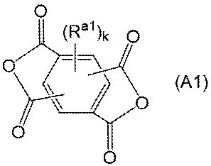
[式(A1)中、Ra1は、互いに独立に、ハロゲン原子、又はハロゲン原子を有してもよいアルキル基、アルコキシ基、アリール基若しくはアリールオキシ基を表し、
kは、0~2の整数を表す]
で表されるテトラカルボン酸無水物由来の構成単位(A1)、及び/又は、式(A2):
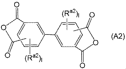
[式(A2)中、Ra2は、互いに独立に、ハロゲン原子、又はハロゲン原子を有してもよいアルキル基、アルコキシ基、アリール基若しくはアリールオキシ基を表し、lは、互いに独立に、0~3の整数である]
で表されるテトラカルボン酸無水物由来の構成単位(A2)を含む、[8]~[11]のいずれかに記載の積層体。
[13] 前記ポリイミド系樹脂含有層(PI-1)及び前記ポリイミド系樹脂含有層(PI-2)の少なくとも1層は、ジアミン由来の構成単位(B)を有するポリイミド系樹脂を含み、
前記構成単位(B)は、式(B1):
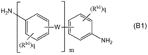
[式(B1)中、Rb1は、互いに独立に、ハロゲン原子、又はハロゲン原子を有してもよいアルキル基、アルコキシ基、アリール基若しくはアリールオキシ基を表し、
Wは、互いに独立に、-O-、-CH2-、-CH2-CH2-、-CH(CH3)-、-C(CH3)2-、-C(CF3)2-、-COO-、-OOC-、-SO-、-SO2-、-S-、-CO-、-N(Rc)-及び-CONH-からなる群から選択される2価の連結基、又は、単結合(但し、mは2以上であり、少なくとも1つのWは前記2価の連結基である)を表し、Rcは水素原子、又はハロゲン原子で置換されていてもよい炭素数1~12の一価の炭化水素基を表し、
mは1~4の整数を表し、
qは互いに独立に、0~4の整数を表す]
で表されるジアミン由来の構成単位(B1)を含む、[8]~[12]のいずれかに記載の積層体。
[14] 少なくとも前記ポリイミド系樹脂含有層(PI-1)は、テトラカルボン酸無水物由来の構成単位(A)を有するポリイミド系樹脂を含み、該構成単位(A)は、式(A3):
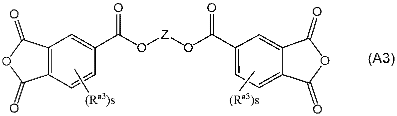
[式(A3)中、Zは2価の有機基を表し、
Ra3は、互いに独立に、ハロゲン原子、又はハロゲン原子を有してもよいアルキル基、アルコキシ基、アリール基若しくはアリールオキシ基を表し、
sは互いに独立に、0~3の整数を表す]
で表されるエステル結合含有テトラカルボン酸無水物由来の構成単位(A3)を含む、[8]~[13]のいずれかに記載の積層体。
[15] 少なくとも前記ポリイミド系樹脂含有層(PI-1)に含まれるポリイミド系樹脂が前記構成単位(A)を有し、該構成単位(A)はさらに、該構成単位(A)の総量に対して50モル%以下の式(A3):
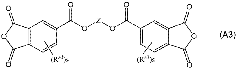
[式(A3)中、Zは2価の有機基を表し、
Ra3は、互いに独立に、ハロゲン原子、又はハロゲン原子を有してもよいアルキル基、アルコキシ基、アリール基若しくはアリールオキシ基を表し、
sは互いに独立に、0~3の整数を表す]
で表されるエステル結合含有テトラカルボン酸無水物由来の構成単位(A3)を含む、[12]~[14]のいずれかに記載の積層体。
[16]前記樹脂フィルムの両面に金属層を有する、[1]~[15]のいずれかに記載の積層体。
[17]前記金属層は銅層である、[1]~[16]のいずれかに記載の積層体。
[18][1]~[17]のいずれかに記載の積層体を含む、フレキシブルプリント回路基板。
前記金属層の前記樹脂フィルムと接する面は、ISO25178に準拠して、レーザー顕微鏡により、観察倍率100倍、Sフィルターによるカットオフ波長0.375μm及びLフィルター無しの条件で測定される最小自己相関長さSal及び表面性状のアスペクト比Strが、式(I):
Sal×Str≧0.21 (I)
の関係を満たす、積層体。
[2] 前記金属層の前記樹脂フィルムと接する面は、前記条件で測定されるコア部のレベル差Skが0.40μm以上である、[1]に記載の積層体。
[3] 前記金属層の前記樹脂フィルムと接する面は、前記条件で測定される最大山高さSpと最大谷深さSvとの差の絶対値が0.48μm以下である、[1]又は[2]に記載の積層体。
[4]前記金属層の前記樹脂フィルムと接する面は、前記条件で測定される展開面積比Sdrが20%以下である、[1]~[3]のいずれかに記載の積層体。
[5] 前記樹脂フィルムは、ポリイミド系樹脂、液晶ポリマー、フッ素系樹脂、芳香族ポリエーテル系樹脂、エポキシ系樹脂及びマレイミド系樹脂からなる群から選択される少なくとも1つの樹脂を含む、[1]~[4]のいずれかに記載の積層体。
[6] 前記樹脂フィルムの熱膨張係数は10~29ppm/Kである、[1]~[5]のいずれかに記載の積層体。
[7]前記樹脂フィルムは、ポリイミド系樹脂を含有するポリイミド系フィルムである、[1]~[6]のいずれかに記載の積層体。
[8] 前記ポリイミド系フィルムは、ポリイミド系樹脂含有層(PI-1)とポリイミド系樹脂含有層(PI-2)とを含む、[7]に記載の積層体。
[9] 前記ポリイミド系樹脂含有層(PI-2)は前記金属層側に位置し、該ポリイミド系樹脂含有層(PI-2)の厚みは、前記ポリイミド系樹脂含有層(PI-1)の厚みの0.05~0.3倍である、[8]に記載の積層体。
[10] 前記ポリイミド系フィルムは、さらにポリイミド系樹脂含有層(PI-3)を含む、[8]又は[9]に記載の積層体。
[11] 前記ポリイミド系樹脂含有層(PI-1)に含まれるポリイミド系樹脂、前記ポリイミド系樹脂含有層(PI-2)に含まれるポリイミド系樹脂、及びポリイミド系樹脂含有層(PI-3)に含まれるポリイミド系樹脂は、それぞれ40℃における貯蔵弾性率が1.0×10⁹Pa以上であるポリイミド系樹脂を含む、[10]に記載の積層体。
[12] 前記ポリイミド系樹脂含有層(PI-1)及び前記ポリイミド系樹脂含有層(PI-2)の少なくとも1層は、テトラカルボン酸無水物由来の構成単位(A)を有するポリイミド系樹脂を含み、
前記構成単位(A)は、式(A1):
kは、0~2の整数を表す]
で表されるテトラカルボン酸無水物由来の構成単位(A1)、及び/又は、式(A2):
で表されるテトラカルボン酸無水物由来の構成単位(A2)を含む、[8]~[11]のいずれかに記載の積層体。
[13] 前記ポリイミド系樹脂含有層(PI-1)及び前記ポリイミド系樹脂含有層(PI-2)の少なくとも1層は、ジアミン由来の構成単位(B)を有するポリイミド系樹脂を含み、
前記構成単位(B)は、式(B1):
Wは、互いに独立に、-O-、-CH2-、-CH2-CH2-、-CH(CH3)-、-C(CH3)2-、-C(CF3)2-、-COO-、-OOC-、-SO-、-SO2-、-S-、-CO-、-N(Rc)-及び-CONH-からなる群から選択される2価の連結基、又は、単結合(但し、mは2以上であり、少なくとも1つのWは前記2価の連結基である)を表し、Rcは水素原子、又はハロゲン原子で置換されていてもよい炭素数1~12の一価の炭化水素基を表し、
mは1~4の整数を表し、
qは互いに独立に、0~4の整数を表す]
で表されるジアミン由来の構成単位(B1)を含む、[8]~[12]のいずれかに記載の積層体。
[14] 少なくとも前記ポリイミド系樹脂含有層(PI-1)は、テトラカルボン酸無水物由来の構成単位(A)を有するポリイミド系樹脂を含み、該構成単位(A)は、式(A3):
Ra3は、互いに独立に、ハロゲン原子、又はハロゲン原子を有してもよいアルキル基、アルコキシ基、アリール基若しくはアリールオキシ基を表し、
sは互いに独立に、0~3の整数を表す]
で表されるエステル結合含有テトラカルボン酸無水物由来の構成単位(A3)を含む、[8]~[13]のいずれかに記載の積層体。
[15] 少なくとも前記ポリイミド系樹脂含有層(PI-1)に含まれるポリイミド系樹脂が前記構成単位(A)を有し、該構成単位(A)はさらに、該構成単位(A)の総量に対して50モル%以下の式(A3):
Ra3は、互いに独立に、ハロゲン原子、又はハロゲン原子を有してもよいアルキル基、アルコキシ基、アリール基若しくはアリールオキシ基を表し、
sは互いに独立に、0~3の整数を表す]
で表されるエステル結合含有テトラカルボン酸無水物由来の構成単位(A3)を含む、[12]~[14]のいずれかに記載の積層体。
[16]前記樹脂フィルムの両面に金属層を有する、[1]~[15]のいずれかに記載の積層体。
[17]前記金属層は銅層である、[1]~[16]のいずれかに記載の積層体。
[18][1]~[17]のいずれかに記載の積層体を含む、フレキシブルプリント回路基板。
本発明によれば、高い耐力を有する積層体を提供することができる。
以下、本発明の実施の形態について、詳細に説明する。なお、本発明の範囲はここで説明する実施の形態に限定されるものではなく、本発明の趣旨を損なわない範囲で種々の変更をすることができる。なお、本明細書に記載されている複数の上限値及び下限値は、任意に組合せて好適な数値範囲とすることができる。
[積層体]
本発明の積層体は、樹脂フィルムと、該樹脂フィルムの少なくとも一方の面に設けられた金属層とを含む。前記金属層の樹脂フィルムと接する面は、ISO25178に準拠して、レーザー顕微鏡により、観察倍率100倍、Sフィルターによるカットオフ波長0.375μm及びLフィルター無しの条件で測定される最小自己相関長さSal及び表面性状のアスペクト比Strが、式(I):
Sal×Str≧0.21 (I)
の関係を満たす。なお、本明細書において、最小自己相関長さSal及び表面性状のアスペクト比Strは、それぞれ単に「Sal」及び「Str」と表記することがあり、後述する他の各粗さパラメータについても同様とする。
本発明の積層体は、樹脂フィルムと、該樹脂フィルムの少なくとも一方の面に設けられた金属層とを含む。前記金属層の樹脂フィルムと接する面は、ISO25178に準拠して、レーザー顕微鏡により、観察倍率100倍、Sフィルターによるカットオフ波長0.375μm及びLフィルター無しの条件で測定される最小自己相関長さSal及び表面性状のアスペクト比Strが、式(I):
Sal×Str≧0.21 (I)
の関係を満たす。なお、本明細書において、最小自己相関長さSal及び表面性状のアスペクト比Strは、それぞれ単に「Sal」及び「Str」と表記することがあり、後述する他の各粗さパラメータについても同様とする。
〔金属層〕
<表面粗さパラメータ>
式(I)中の最小自己相関長さSalは、金属表面の凹凸状態の密集度合を長さの単位で数値化したものであり、面粗さの空間パラメータの1つである。より詳細には、Salは、表面粗さの平面方向の周期性を表し、自己相関関数が特定の値へ減衰する方向の水平距離を示す。Salが小さいほど急激な段差があることを示し、Salが大きいほどなだらかな形状であることを示す。また、式(I)中の表面性状のアスペクト比Strは、金属表面の等方性又は異方性の強さを定量化した三次元表面性状パラメータであり、0以上1以下の値をとる。Strが1に近い場合、金属表面は強い等方性を示し、表面の凹凸に規則的な方向性が見られないこと、すなわち表面に筋目等がないことを意味する。Strが0に近い場合、金属表面は強い異方性を示し、表面の凹凸に規則的な方向性が見られること、すなわち表面に筋目等があることを意味する。
本発明者は、樹脂フィルムと金属層との界面に着目して検討を進めたところ、金属層の樹脂フィルムと接する面において、特定の条件で測定されるSal及びStrが式(I)を満たすと、意外なことに、積層体の0.2%耐力が向上することを見出した。この理由は定かではないが、積層体の厚み方向断面において、界面の凹凸状態により、樹脂フィルム及び金属層それぞれに働く応力集中の状態が異なり、界面において誘発される歪みや発生した内部応力の大きさが異なると考えられ、また界面付近の樹脂層の結晶性や配向性も変化することが予想される。金属層の樹脂フィルムと接する面が式(I)を満たす場合、金属表面において傾斜の緩やかな凸部、凹部がランダムに存在する表面性状となり得る。そのため、界面での応力集中が生じにくく、また成膜時に前記表面性状の影響を受け、積層体における界面付近の樹脂層の結晶性及び/又は配向性が高まり、積層体全体として変形に対する強さが向上するからだと考えられる。
本発明の一実施形態において、積層体を金属積層板等として使用する場合、エッチング等により、樹脂フィルム上の金属層が部分的に除かれることがある。かかる積層体において、誘電特性及びFPC製造時の乾燥効率の観点から、金属層除去後の樹脂フィルムの耐水性が高いことが好ましい。本発明者らは、金属層の樹脂フィルムと接する面が式(I)を満たすと、意外なことに、金属層除去後の樹脂フィルムの耐水性及び乾燥速度が向上し得ることも見出した。この理由は定かではないが、式(I)を満たすと、樹脂層表面の凹凸性状が水を吸収しにくい凹凸構造をとりやすくなり、また積層体の界面付近における樹脂層の結晶性及び/又は配向性が高まり、耐水性や乾燥速度の点で有利となり得るためだと推定される。本明細書において、耐水性は、積層体において金属層除去後の樹脂フィルムを純水に浸漬させた際に含水しにくい特性を示し、例えば実施例に記載の方法により評価できる。また、乾燥速度は、金属層除去後の樹脂フィルムを含水させた後、加熱乾燥した際に純水が減少する速度を示し、例えば実施例に記載の方法により評価できる。金属層を除去した後の樹脂フィルムの耐水性及び乾燥速度は、積層体の特性ともいえるため、それぞれ積層体の耐水性、積層体の乾燥速度と称する。
本明細書において、誘電特性とは、Df、Dk等の誘電に関する特性を意味し、誘電特性が高まる又は向上するとは、Df及び/又はDkが低減することをいう。積層体の誘電特性は、積層体中の樹脂フィルムの誘電特性により評価できる。また、機械物性とは、耐力、突刺強度、屈曲耐性、及び、弾性率を含む機械的物性を意味し、機械物性が高まる又は向上するとは、例えば、耐力、屈曲耐性、及び/又は弾性率が高くなることをいう。さらに、熱物性には、CTE、ガラス転移温度(以下、Tgと記載することがある)、熱による変性や劣化の程度等が含まれ得、熱物性が高まる又は向上するとは、例えば、CTEが低くなること、Tgが高くなること、及び/又は、熱による変性や劣化が少ないこと等を意味する。
本明細書において、誘電特性とは、Df、Dk等の誘電に関する特性を意味し、誘電特性が高まる又は向上するとは、Df及び/又はDkが低減することをいう。積層体の誘電特性は、積層体中の樹脂フィルムの誘電特性により評価できる。また、機械物性とは、耐力、突刺強度、屈曲耐性、及び、弾性率を含む機械的物性を意味し、機械物性が高まる又は向上するとは、例えば、耐力、屈曲耐性、及び/又は弾性率が高くなることをいう。さらに、熱物性には、CTE、ガラス転移温度(以下、Tgと記載することがある)、熱による変性や劣化の程度等が含まれ得、熱物性が高まる又は向上するとは、例えば、CTEが低くなること、Tgが高くなること、及び/又は、熱による変性や劣化が少ないこと等を意味する。
式(I)中のSal×Strは、好ましくは0.23μm以上、より好ましくは0.25μm以上、さらに好ましくは0.30μm以上、さらにより好ましくは0.40μm以上、特に好ましくは0.50μm以上、特により好ましくは1.0μm以上、2.0μm以上、3.0μm以上、5.0μm以上、又は7.0μm以上、特にさらに好ましくは8.0μm以上、特にさらにより好ましくは8.5μm以上、極めて好ましくは9.5μm以上である。また、式(I)中のSal×Strは、好ましくは20μm以下、より好ましくは17μm以下、さらに好ましくは15μm以下、さらにより好ましくは13μm以下、特に好ましくは12.0μm以下、特により好ましくは11.5μm以下、11.0μm以下、又は10.5μm以下である。Sal×Strが前記下限以上及び/又は上限以下であると、積層体における界面の凹凸構造や樹脂層の結晶性及び/又は配向性が、本発明の効果をより一層発明できる状態になりやすいため、積層体の耐力、耐水性や乾燥速度をより向上できる。
本発明の一実施形態において、前記最小自己相関長さSalは、式(I)を満たしていれば特に限定されないが、例えば0.50μm以上、1.00μm以上、1.30μm以上、1.50μm以上、又は2.00μm以上であってもよく、好ましくは2.2μm以上、より好ましくは3.0μm以上、さらに好ましくは5.0μm以上、さらにより好ましくは7.0μm以上、特に好ましくは10.0μm以上、特により好ましくは11.0μm以上、特にさらに好ましくは11.6μm以上である。また、式(I)中のSalは、例えば30μm以下、25μm以下、又は20μm以下であってもよく、好ましくは17μm以下、より好ましくは15μm以下、さらに好ましくは14.0μm以下である。式(I)中のSalが前記範囲内であると、積層体の耐力、耐水性や乾燥速度を高めることができる。
本発明の一実施形態において、前記表面性状のアスペクト比Strは、式(I)を満たしていれば特に限定されないが、例えば0.05以上であってもよく、好ましくは0.07以上、より好ましくは0.10以上、さらに好ましくは0.20以上、さらにより好ましくは0.30以上、特に好ましくは0.50以上、特により好ましくは0.60以上、特にさらに好ましくは0.81以上であり、好ましくは0.98以下、より好ましくは0.95以下、さらに好ましくは0.90以下である。式(I)中のStrが前記範囲内であると、積層体の耐力、耐水性や乾燥速度を高めることができる。
本発明の一実施形態において、金属層の樹脂フィルムと接する面は、上記の測定条件で測定されるコア部のレベル差Skが0.40μm以上であることが好ましい。コア部のレベル差Skは、突出凸部と突出凹部を除いたコア部の最大高さから最小高さを差し引いたものであり、コア部の高さのバラツキを表す。前記Skは、より好ましくは0.42μm以上、さらに好ましくは0.44μm以上であり、好ましくは2.0μm以下、より好ましくは1.0μm以下、さらに好ましくは0.60μm以下、さらにより好ましくは0.55μm以下、特に好ましくは0.50μm以下である。Skが前記下限以上及び/又は上限以下であると、積層体の耐力、耐水性や乾燥速度を向上できる。このような効果が得られる理由は定かではないが、Skが前記範囲内であると、金属表面において大きすぎる凹凸部を有さず、さらに金属表面と樹脂との接触面積が適度に存在する表面性状となり得る。そのため、界面での応力集中が生じにくい凹凸性状となりやすく、また成膜時に該表面性状の影響を受け、積層体における界面付近の樹脂層の結晶性及び/又は配向性が高まり、積層体全体として変形に対する強さが向上するからだと推定される。さらに、樹脂フィルム表面の凹凸性状が水を吸収しにくい凹凸構造をとりやすく、また樹脂層の表面(つまり、積層体時の樹脂フィルム側の界面)付近の結晶性及び/又は配向性が高まることで耐水性や乾燥速度の点でも有利になるからだと推定される。
本発明の一実施形態において、金属層の樹脂フィルムと接する面は、上記の測定条件で測定される最大山高さSpと最大谷深さSvとの差の絶対値(|Sp-Sv|と表記することがある)が好ましくは0.48μm以下、より好ましくは0.45μm以下又は0.40μm以下、さらに好ましくは0.33μm以下、さらにより好ましくは0.27μm以下、特に好ましくは0.25μm以下、特により好ましくは0.15μm以下、特にさらに好ましくは0.10μm以下、極めて好ましくは0.04μm以下であり、例えば0.03μm以下、又は0.02μm以下であってもよい。また、前記|Sp-Sv|は、好ましくは0.001μm以上、より好ましくは0.005μm以上である。前記|Sp-Sv|が前記上限以下及び/又は前記下限以上であると、積層体の耐力、耐水性や乾燥速度を向上できる。このような効果が得られる理由は定かではないが、|Sp-Sv|が前記範囲内であると、界面の凹凸が歪な表面性状となり得る。そのため、界面での応力集中が生じにくく、また成膜時に前記表面性状の影響を受け、積層体における界面付近の樹脂層の結晶性及び/又は配向性が高まり、積層体全体として変形に対する強さが向上するからだと推定される。さらに、樹脂フィルム表面の凹凸性状が水を吸収しにくい凹凸構造をとりやすく、また樹脂層の表面(つまり、積層体時の樹脂フィルム側の界面)付近の結晶性及び/又は配向性が高まることで耐水性や乾燥速度の点でも有利になるからだと推定される。
本発明の一実施形態において、前記最大山高さSpは、好ましくは2.00μm以下、より好ましくは1.70μm以下、さらに好ましくは1.50μm以下、さらにより好ましくは1.20μm以下、特に好ましくは1.10μm以下又は1.00μm以下、特により好ましくは0.90μm以下であり、好ましくは0.10μm以上、より好ましくは0.30μm以上、さらに好ましくは0.50μm以上、さらにより好ましくは0.70μm以上である。前記Spが前記範囲内であると、積層体の耐力、耐水性や乾燥速度を高めることができる。
本発明の一実施形態において、前記最大谷深さSvは、好ましくは1.50μm以下、より好ましくは1.30μm以下であり、例えば1.20μm以下、1.00μm以下、又は0.90μm以下であってもよく、好ましくは0.30μm以上、より好ましくは0.50μm以上、さらに好ましくは0.70μm以上である。Svが前記範囲内であると、積層体の耐力、耐水性や乾燥速度を高めることができる。
本発明の一実施形態において、金属層の樹脂フィルムと接する面は、上記の測定条件で測定される展開面積比Sdrが、例えば100%以下又は50%以下であってもよく、好ましくは35.0%以下、より好ましくは20%以下である。展開面積比Sdrは、定義領域の展開面積(すなわち表面積)が、定義領域の面積に対してどれだけ増大しているかを表すものであり、具体的には完全に平坦な表面を100%としたときに、完全に平坦な表面からの表面積の増加率を表す。Sdrが小さいほど平坦に近い表面形状であることを示し、完全に平坦な表面のSdrは0%となる。一方、Sdrが大きいほど、凹凸が多い表面形状であることを示す。前記Sdrは、より好ましくは20%未満、さらに好ましくは18%以下又は15%以下、さらにより好ましくは13%以下、特に好ましくは10%以下、特により好ましくは5%以下であり、好ましくは0.5%以上、より好ましくは1.0%以上、さらに好ましくは2%以上である。展開面積比Sdrが前記上限以下及び/又は下限以上であると、積層体の耐力、耐水性や乾燥速度を高めることができる。このような効果が得られる理由は定かではないが、Sdrが前記範囲内であると、金属表面において適度な凹凸部を有し、さらに金属表面と樹脂との接触面積が適度に存在する表面性状となり得る。そのため、界面での応力集中が生じにくい凹凸性状となりやすく、また成膜時に該表面性状の影響を受け、積層体における界面付近の樹脂層の結晶性及び/又は配向性が高まり、積層体全体として変形に対する強さが向上するからだと推定される。さらに、樹脂フィルム表面の凹凸性状が水を吸収しにくい凹凸構造をとりやすく、また樹脂層の表面(つまり、積層体時の樹脂フィルム側の界面)付近の結晶性及び/又は配向性が高まることで耐水性や乾燥速度の点でも有利になるからだと推定される。
本発明の一実施形態において、金属層の樹脂フィルムと接する面は、上記の測定条件で測定されるスキューネスSkuが、好ましくは3.80以下、より好ましくは3.50以下であり、好ましくは1.0以上、より好ましくは1.5以上、さらに好ましくは2.0以上、さらにより好ましくは2.5以上、特に好ましくは2.8以上、特により好ましくは3.00以上、特にさらに好ましくは3.10以上、極めて好ましくは3.30以上である。前記Skuが前記範囲内であると、積層体の耐力、耐水性や乾燥速度を高めることができる。レーザー顕微鏡により得られるスキューネスSkuは、金属層表面の高さ分布の鋭さを示す指標である。
Skuは、鋭さの尺度である尖度を意味し、高さ分布の鋭さ(尖り)を表す。Sku>3のときは、尖った凸部や凹部が多いことを意味し、Sku<3のときは、先端がつぶれているような凹凸部が多く、表面が比較的平坦な形状であることを意味し、Sku=3のときは、高さ分布が正規分布であることを意味する。
本発明の一実施形態において、金属層の樹脂フィルムと接する面は、上記の測定条件で測定される算術平均高さSaが、例えば0.05μm以上又は0.10μm以上であってもよく、好ましくは0.14μm以上であり、また例えば0.5μm以下、0.4μm以下、又は0.3μm以下であってもよく、好ましくは0.25μm未満、より好ましくは0.22μm以下、さらに好ましくは0.20μm以下、さらにより好ましくは0.17μm以下又は0.16μm以下である。前記Saが前記範囲内であると、積層体の耐力、耐水性や乾燥速度を高めることができる。算術平均高さSaは、二次元のパラメータであるRaを三次元に拡張したパラメータであり、平均面からの高低差の平均値を表す。
本発明の一実施形態において、金属層の樹脂フィルムと接する面は、上記の測定条件で測定される最大高さSzは、好ましくは3.5μm以下、より好ましくは3.0μm以下、さらに好ましくは2.8μm以下、2.50μm以下又は2.1μm以下、さらにより好ましくは2.00μm以下、特に好ましくは1.90μm以下又は1.80μm以下であり、好ましくは0.1μm以上、より好ましくは0.5μm以上、さらに好ましくは1.0μm以上、さらにより好ましくは1.3μm以上、特に好ましくは1.5μm以上である。前記Szが前記範囲内であると、積層体の耐力、耐水性や乾燥速度を高めることができる。
本明細書において、Sal、Str、Sk、Sdr、Sp、Sv、Sku、Sa、Sz、Sal×Str、及び|Sp-Sv|等を総称して、金属表面の「表面粗さパラメータ」ということがある。
本発明の一実施形態では、金属層の樹脂フィルムと接する面において、JIS B0601:2013に準拠して、レーザー顕微鏡により、観察倍率100倍の条件で測定される算術平均高さRaは、好ましくは0.01~0.5μm、より好ましくは0.05~0.3μm、さらに好ましくは0.1~0.25μmであり、例えば0.12~0.20μmであってもよい。また、最大高さRzは、好ましくは0.1~2μm、より好ましくは0.5~1.6μmであり、例えば0.60~1.0μmであってもよい。また、十点平均粗さRzjisは、好ましくは0.05~2μm、より好ましくは0.1~1.5μm、さらに好ましくは0.2~1.0μm、さらにより好ましくは0.30~0.80μm、特に好ましくは0.30~0.70μmである。
金属表面の表面粗さパラメータは、レーザー顕微鏡を用いて、観察倍率100倍にて、金属層の樹脂フィルムと接する側の面をレーザー観察して三次元的形状像を取得し、取得した三次元的形状像を解析することにより測定できる。Sal、Str、Sk、Sdr、Sp、Sv、Sku、Sa及びSzの解析は、ISO 25178にそれぞれ準拠して、Sフィルターによるカットオフ波長0.375μm及びLフィルター無しの条件で行うことができ、Ra、Rz及びRzjisの解析は、JIS B0601:2013に準拠して、取得した三次元的形状像において、λsが2.5μm、λc及びλfが設定無しの条件で、任意の箇所で取得した輪郭曲線を解析することにより行うことができる。金属表面の表面粗さパラメータは、例えば実施例に記載の方法により求められる。
金属層は、例えば、電気メッキ法等の電解鋳造法や圧延等の塑性加工により製造してもよく、市販品を用いてもよい。金属層が金属箔の場合、該金属箔の少なくとも片方の表面に、電気メッキにより表面処理層が設けられていてもよく、表面処理層としては、粗化層や防錆層、さらに必要に応じて金属箔の表面と前記粗化層の間に設けられる合金層、防錆層の表面に設けられるクロメート層やシランカップリング剤層等が挙げられる。金属層が銅箔の場合、電解銅箔や圧延銅箔を使用することができ、該金属層は、銅、亜鉛、チタン、タングステン、モリブデン、ニッケル、コバルト、鉄、若しくはこれらのうちの2つ以上の元素からなる粗化層、及び/又は、亜鉛、錫、ニッケル、コバルト、クロム、モリブデン、若しくはこれらのうちの2つ以上の元素からなる防錆層を有するものであることが好ましい。粗化層を均一に設ける観点からは、さらに、銅と、モリブデン、亜鉛、タングステン、ニッケル、コバルト及び鉄から選ばれる少なくとも1種以上の元素との合金層を銅箔の表面に設けておくことが好ましい。本明細書では、前記表面処理層も含めて「金属層」と称する。金属層は、上記表面粗さパラメータの範囲を満たす市販品を使用してもよく、例えば金属表面に所定の粗さを有する表面処理層を形成すること等により、表面粗さパラメータを上記範囲内に調整してもよい。
前記表面処理層の厚さは、金属箔表面の表面粗さパラメータを調整しやすい観点から、2.0μm以下、好ましくは0.2μm以上1.5μm以下である。
本発明の積層体が樹脂フィルムの両面に金属層を含む場合、少なくとも一方の金属層が樹脂フィルムと接する面において式(I)を満たせばよい。積層体の耐力、耐水性や乾燥速度の観点からは、両方の金属層が樹脂フィルムと接する面において式(I)を満たしていてもよい。また、各表面粗さパラメータは、一方の金属層が樹脂フィルムと接する面と、他方の金属層が樹脂フィルムと接する面において、同一であっても異なっていてもよい。
<金属層の種類及び厚さ>
金属層は、樹脂フィルムの少なくとも一方の面に設けられている。すなわち、金属層は、樹脂フィルムの片面のみに設けられていても、両面に設けられていてもよい。
金属層は、樹脂フィルムの少なくとも一方の面に設けられている。すなわち、金属層は、樹脂フィルムの片面のみに設けられていても、両面に設けられていてもよい。
本発明の一実施形態において、金属層を構成する金属としては、例えば、アルミニウム、銅、鉄、ニッケル、クロム、チタン、タンタル、ステンレス及びこれらの合金等が挙げられる。これらの中でも、金属層は、銅層、銅合金層、SUS層、アルミニウム層等が好ましく、導電性及び金属加工性の観点から、銅層又は銅合金層がより好ましく、銅層が特に好ましい。また、金属加工性の観点から、金属層は、金属箔層であることが好ましく、前記例示の各金属の金属箔がより好ましく、銅箔層又は銅合金箔層がさらに好ましく、銅箔層が特に好ましい。
本発明の一実施形態において、金属層、特に銅層の厚さは、好ましくは1μm以上、より好ましくは5μm以上、さらに好ましくは10μm以上であり、また、回路の微細化をしやすく、屈曲耐性を向上しやすい観点から、好ましくは100μm以下、より好ましくは50μm以下、さらに好ましくは30μm以下、特に好ましくは20μm以下である。金属層、特に銅層の厚さは、膜厚計等を用いて測定できる。なお、樹脂フィルムの両面に金属層、特に銅層を含む場合、各金属層、特に各銅層の厚さは互いに同じであっても異なっていてもよい。
〔樹脂フィルム〕
本発明の積層体は樹脂フィルムを含む。樹脂フィルムを構成する樹脂としては、特に限定されず、ジアリルフタレート樹脂、シリコーン樹脂、フェノール樹脂、不飽和ポリエステル樹脂、ポリウレタン樹脂、メラミン樹脂、尿素樹脂、キシレン樹脂、フラン樹脂、アニリン樹脂、アセトン-ホルムアルデヒド樹脂、アルキド樹脂、マレイミド系樹脂、マレイミド-シアン酸エステル樹脂、シアン酸エステル樹脂、ベンゾオキサジン樹脂、ポリベンズイミダゾール樹脂、及びポリカルボジイミド樹脂から選択される熱硬化性樹脂;オレフィン系樹脂;アクリル系樹脂;スチレン系樹脂;ゴム系樹脂;フッ素系樹脂;ビニル系樹脂;汎用エンジニアリングプラスチック;液晶ポリマー、芳香族ポリエーテル系樹脂などのスーパーエンジニアリングプラスチック;ポリアミド樹脂;ポリイミド樹脂、ポリアミドイミド樹脂などのポリイミド系樹脂;並びに生分解性プラスチックなどが挙げられる。これらの樹脂は単独又は二種以上組み合わせて使用できる。これらの中でも、積層体の耐力、耐水性、乾燥速度や誘電特性を高める観点から、樹脂フィルムは、ポリイミド系樹脂、液晶ポリマー、フッ素系樹脂、芳香族ポリエーテル系樹脂、エポキシ系樹脂及びマレイミド系樹脂からなる群から選択される少なくとも1つの樹脂を含むことが好ましく、ポリイミド系樹脂及び/又は液晶ポリマーを含むことがより好ましく、ポリイミド系樹脂を含むことがさらに好ましい。
樹脂フィルムを構成する少なくとも1つの樹脂は、配向性及び/又は結晶性を有するものであることが好ましい。樹脂フィルム中の樹脂の配向性については、レーザーラマン分光法等により確認することができ、結晶性については小角X線散乱法、広角X線散乱法やIR測定により確認することができる。
樹脂フィルムを構成する樹脂における重量平均分子量、重量平均分子量と数平均分子量との比、ガラス転移温度や引張弾性率は、特に限定されないが、例えば、後述のポリイミド系樹脂と同じ範囲から選択することができる。
本発明の好適な実施形態では、前記樹脂フィルムは、好ましくはポリイミド系樹脂を含有するポリイミド系フィルムである。ポリイミド系樹脂を含有すると、積層体の耐力、耐水性や乾燥速度を向上することができる。本明細書において、ポリイミド系フィルムを「PI系フィルム」ということがあり、ポリイミド系樹脂を「PI系樹脂」ということがある。
樹脂フィルムは、単層フィルムであっても積層フィルムであってもよい。
本発明の好適な実施形態において、PI系フィルムが積層フィルムである場合、ポリイミド系樹脂含有層(PI-1)とポリイミド系樹脂含有層(PI-2)とを含むことが好ましい。PI系フィルムは、これらのPI系樹脂含有層以外の他のPI系樹脂含有層を含んでいてもよく、PI系樹脂含有層以外の他の層を含んでいてもよい。他の層としては、粘接着剤層などが挙げられる。本発明の好適な実施形態では、積層体の耐力を高める観点から、本発明におけるPI系フィルムは、PI系樹脂含有層(PI-1)及びPI系樹脂含有層(PI-2)に加え、さらにPI系樹脂含有層(PI-3)を含むことが好ましい。かかる実施形態では、本発明におけるPI系フィルムは、積層体の耐力を高める観点から、PI系樹脂含有層(PI-2)、PI系樹脂含有層(PI-1)及びPI系樹脂含有層(PI-3)をこの順に含むことが好ましく、互いに隣接してこの順に含むことがより好ましい。なお、PI系樹脂含有層(PI-1)、PI系樹脂含有層(PI-2)及びPI系樹脂含有層(PI-3)(PI系樹脂含有層(PI-1)~(PI-3)又は層(PI-1)~(PI-3)と表記することがある)を含むPI系フィルムをPI系フィルム(L)ということがある。また、本明細書において、「PI系フィルム」は、特に言及しない限り、単層フィルムと積層フィルムの両方を含み、PI系樹脂含有層、特にPI系樹脂含有層(PI-1)、PI系樹脂含有層(PI-2)及び/又はPI系樹脂含有層(PI-3)について言及している場合は、積層フィルム形態のPI系フィルムに関する。
本発明の好適な実施形態におけるPI系フィルム10は、図1に示されるように、3層の隣接するPI系樹脂含有層11、PI系樹脂含有層12及びPI系樹脂含有層13から構成され、金属層14上に積層されて積層体15を構成し、積層体の耐力、耐水性、乾燥速度や誘電特性を高める観点からは、好ましくはPI系樹脂含有層11が層(PI-2)に、PI系樹脂含有層12が層(PI-1)に、PI系樹脂含有層13が層(PI-3)に相当する。また、PI系フィルム10は、層(PI-1)、層(PI-2)及び層(PI-3)以外の他のPI系樹脂含有層や、PI系樹脂含有層以外の他の層を含んでいてもよい。他の層としては、PI系樹脂以外のアクリル系樹脂などの高分子材料等から形成される粘接着剤層などが挙げられる。
本発明の一実施形態において、樹脂フィルムの厚みは、好ましくは20μm以上、より好ましくは25μm以上、さらに好ましくは30μm以上、さらにより好ましくは35μm以上、特に好ましくは40μm以上であり、好ましくは150μm以下、より好ましくは130μm以下、さらに好ましくは100μm以下、さらにより好ましくは90μm以下、特に好ましくは80μm以下、特により好ましくは70μm以下、特にさらに好ましくは60μm以下である。樹脂フィルムの厚みが前記範囲内であると、積層体が高い耐力やフレキシブルプリント回路基板等に適する柔軟性などの機械物性を備え得る。また、Dfを低減するとともに、耐力を向上させ得るため、フレキシブルプリント回路基板に適する機械物性と5G等の高速通信用途に適する誘電特性とをバランスよく備えた積層体を得ることができる。
本発明におけるPI系フィルムが積層フィルムである場合、フィルムの厚みは上記樹脂フィルムの厚みの範囲から選択できるが、層(PI-1)の厚みは10μm以上であることが好ましく、層(PI-2)の厚みは2μm以上であることが好ましい。層(PI-1)及び層(PI-2)の厚みが前記下限以上であると、積層体の耐力をより向上できる。層(PI-1)の厚みは、より好ましくは15μm以上、さらに好ましくは20μm以上、さらにより好ましくは30μm以上であり、好ましくは80μm以下、より好ましくは60μm以下、さらに好ましくは55μm以下、さらにより好ましくは50μm以下である。また、層(PI-2)の厚みは、より好ましくは2.5μm以上、さらに好ましくは3μm以上、さらにより好ましくは3.5μm以上であり、好ましくは20μm以下、より好ましくは15μm以下、さらに好ましくは10μm以下、さらにより好ましくは8μm以下である。
本発明におけるPI系フィルムが層(PI-3)を有する場合、層(PI-3)の厚みは、上記層(PI-2)の厚みの範囲から選択してもよい。層(PI-2)の厚みと層(PI-3)の厚みとは、互いに同じであっても、異なっていてもよいが、積層体の反りを抑制する観点からは、好ましくは一方の値が他方の値の±25%の範囲内、より好ましくは±20%の範囲内である。なお、各層の厚みは、レーザー顕微鏡等を用いて測定でき、例えば実施例に記載の方法により測定できる。
本発明の一実施形態において、層(PI-2)の厚みは、層(PI-1)の厚みの0.05~0.3倍であることが好ましい。前記厚みが前記関係にある場合、積層体が高い耐力やフレキシブルプリント回路基板等に適する柔軟性などの機械物性を備え得る。また、Dfを低減するとともに耐力を向上させ得るため、フレキシブルプリント回路基板に適する機械物性と5G等の高速通信用途に適する誘電特性とをバランスよく備えた積層体を得ることができる。特に、層(PI-2)が金属層側に位置し、かつ層(PI-2)の厚みが、層(PI-1)の厚みの0.05~0.3倍である場合、又は、PI系フィルムの厚みが20~100μmであり、かつ層(PI-2)の厚みが、層(PI-1)の厚みの0.05~0.3倍である場合に前記本発明の効果はより得られやすくなる。層(PI-2)の厚みは、層(PI-1)の厚みに対し、より好ましくは0.08倍以上、さらに好ましくは0.10倍以上、特に好ましくは0.12倍以上であり、より好ましくは0.25倍以下、さらに好ましくは0.23倍以下、特に好ましくは0.20倍以下である。なお、本発明におけるPI系フィルムが層(PI-3)を有する場合、層(PI-3)の厚みは、上記層(PI-2)の範囲から選択してもよい。
本発明におけるPI系フィルムにおいて、層(PI-1)~層(PI-3)を構成するPI系樹脂は、その種類は特に限定されないが、優れた誘電特性を維持しつつ、耐力を高める観点から、層(PI-1)~層(PI-3)はそれぞれ、非熱可塑性のポリイミド系樹脂含有層(以下、mPI層と記載することがある)及び/又は熱可塑性のポリイミド系樹脂含有層(以下、TPI層と記載することがある)を含むことが好ましい。特に、耐力を高める観点から、層(PI-1)及び層(PI-2)はそれぞれ、mPI層又はTPI層であることが好ましく、層(PI-1)及び層(PI-2)のうち、一方はmPI層であり、他方はTPI層であることがより好ましい。
mPI層は、一般に、フレキシブルプリント回路基板用途のPI系フィルムにおいて主となるPI系樹脂含有層となる。TPI層は、PI系フィルムを金属層(例えば銅層)と接着する接着層としても機能し得る層であり、PI系フィルムにおいて金属層と接し得る最外層に位置することが好ましい。
PI系樹脂含有層を3層以上含むPI系フィルムにおいては、少なくとも1層のPI系樹脂含有層がmPI層であり、少なくとも1層(好ましくは少なくとも2層)のPI系樹脂含有層がTPI層であることが好ましく、TPI層、mPI層、TPI層をこの順に備えることがより好ましい。したがって、PI系フィルム(L)においては、層(PI-1)はmPI層であることが好ましく、層(PI-2)及び層(PI-3)はそれぞれTPI層であることが好ましい。PI系フィルム(L)がこのような層構成であると、mPI層において向上した熱物性を確保して、熱変性や劣化を抑制し、PI系フィルムの寸法安定性を確保し得るとともに、TPI層によって金属層(例えば銅層)との接着性を高めることができ、さらにはPI系フィルムの耐力を向上することができる。
PI系フィルム(L)に複数層のTPI層又はmPI層が含まれる場合、複数層含まれるTPI層又はmPI層の構成はそれぞれ同じであっても、異なっていてもよい。また、PI系フィルム(L)においては、通常、層(PI-1)と、層(PI-2)及び層(PI-3)との構成は異なるが、層(PI-2)と層(PI-3)との構成は同じであっても、異なっていてもよい。
本発明の好適な別の実施形態において、PI系フィルムが単層フィルムである場合、1つのPI系樹脂含有層から構成され、その種類は特に限定されず、優れた誘電特性を維持しつつ、耐力を高める観点から、前記層(PI-1)の構成を採用することが好ましい。PI系フィルムが単層フィルムの場合、フィルムの厚みは、上記樹脂フィルムの厚みの範囲から選択できる。
<PI系樹脂>
PI系フィルムに含まれるPI系樹脂は、イミド基を含む繰返し構造単位を含有する樹脂であり、イミド基及びアミド基の両方を含む繰り返し構造単位を含んでいてもよい。なお、本発明において「非熱可塑性」のポリイミド系樹脂とは、動的粘弾性測定装置(DMA)を用いて測定した40℃における貯蔵弾性率が1.0×10⁹Pa以上であり、かつ、300℃における貯蔵弾性率が1.0×10⁸Pa以上であるポリイミド系樹脂を意味し、「熱可塑性」のポリイミド系樹脂とは、40℃における貯蔵弾性率が1.0×10⁹Pa以上であり、かつ、300℃における貯蔵弾性率が1.0×10⁸Pa未満であるポリイミド系樹脂を意味する。なお、貯蔵弾性率は、例えば実施例に記載の方法により測定できる。
PI系フィルムに含まれるPI系樹脂は、イミド基を含む繰返し構造単位を含有する樹脂であり、イミド基及びアミド基の両方を含む繰り返し構造単位を含んでいてもよい。なお、本発明において「非熱可塑性」のポリイミド系樹脂とは、動的粘弾性測定装置(DMA)を用いて測定した40℃における貯蔵弾性率が1.0×10⁹Pa以上であり、かつ、300℃における貯蔵弾性率が1.0×10⁸Pa以上であるポリイミド系樹脂を意味し、「熱可塑性」のポリイミド系樹脂とは、40℃における貯蔵弾性率が1.0×10⁹Pa以上であり、かつ、300℃における貯蔵弾性率が1.0×10⁸Pa未満であるポリイミド系樹脂を意味する。なお、貯蔵弾性率は、例えば実施例に記載の方法により測定できる。
PI系フィルムを構成するPI系樹脂は、積層体の耐力、耐水性、乾燥速度や誘電特性を高める観点から、テトラカルボン酸無水物由来の構成単位(A)とジアミン由来の構成単位(B)とを含むことが好ましい。なお、本発明において「由来の構成単位」とは、「由来する構成単位」を意味し、例えば「テトラカルボン酸無水物由来の構成単位(A)」は「テトラカルボン酸無水物に由来する構成単位(A)」を意味する。また、「PI系フィルムが構成単位(A)を含む」とは、該「PI系フィルムを構成するPI系樹脂が構成単位(A)を含む」ことを意味し、「PI系樹脂含有層が構成単位(A)を含む」とは、該「PI系樹脂含有層を構成するPI系樹脂が構成単位(A)を含む」ことを意味し、他の構成単位においても同様である。また、本明細書において、PI系フィルムを構成する(若しくは該PI系フィルムに含まれる)PI系樹脂は、特に言及しない限り、PI系樹脂含有層の少なくとも1層、層(PI-1)及び層(PI-2)の少なくとも1層、又は層(PI-1)~層(PI-3)の少なくとも1層を構成する(若しくは該少なくとも1層に含まれる)PI系樹脂に読み替えることができる。
(テトラカルボン酸無水物由来の構成単位(A))
テトラカルボン酸無水物由来の構成単位(A)(以下、単に、構成単位(A)と略すことがある)は、例えば、式(1):
[式(1)中、Yは4価の有機基を表す]
で表されるテトラカルボン酸無水物由来の構成単位であることが好ましい。
テトラカルボン酸無水物由来の構成単位(A)(以下、単に、構成単位(A)と略すことがある)は、例えば、式(1):
で表されるテトラカルボン酸無水物由来の構成単位であることが好ましい。
式(1)において、Yは、互いに独立に4価の有機基を表し、好ましくは炭素数4~40の4価の有機基を表し、より好ましくは環状構造を有する炭素数4~40の4価の有機基を表す。環状構造としては、脂環、芳香環、ヘテロ環構造が挙げられる。前記有機基は、有機基中の水素原子がハロゲン原子、炭化水素基、アルコキシ基又はハロゲン化炭化水素基で置換されていてもよく、その場合、これらの基の炭素数は好ましくは1~8である。本発明においてPI系樹脂は、複数種のYを含み得、複数種のYは、互いに同一であってもよく、異なっていてもよい。Yとしては、式(31)~式(40)で表される基又は構造;式(31)~式(40)で表される基中の水素原子がメチル基、エチル基、n-プロピル基、イソプロピル基、n-ブチル基、イソブチル基、sec-ブチル基、tert-ブチル基、フルオロ基、クロロ基又はトリフルオロメチル基で置換された基;4価の炭素数1~8の鎖式炭化水素基などが挙げられる。
V1及びV2は、互いに独立に、単結合(ただし、e+d=1のときを除く)、-O-、-CH2-、-CH2-CH2-、-CH(CH3)-、-C(CH3)2-、-C(CF3)2-、-SO2-、-S-、-CO-、-N(Rj)-、又は式(a)
Dは互いに独立に、単結合、-C(CH3)2-又は-C(CF3)2-を表し、
iは1~3の整数を表し、
*は結合手を表す)
を表し、
Rjは、水素原子、又はハロゲン原子で置換されていてもよい炭素数1~12の一価の炭化水素基を表し、
e及びdは、互いに独立に、0~2の整数を表し(ただし、e+dは0ではない)、
fは0~3の整数を表し、
g及びhは、互いに独立に、0~4の整数を表し、
式(39)中、Zは2価の有機基を表し、
Ra3は、互いに独立に、ハロゲン原子、又はハロゲン原子を有してもよいアルキル基、アルコキシ基、アリール基若しくはアリールオキシ基を表し、
sは互いに独立に、0~3の整数を表し、
式(40)中、Ra2は、互いに独立に、ハロゲン原子、又はハロゲン原子を有してもよいアルキル基、アルコキシ基、アリール基若しくはアリールオキシ基を表し、
lは、互いに独立に、0~3の整数を表し、
*は結合手を表す]。
本発明において、PI系フィルムを構成するPI系樹脂は、積層体の耐力、耐水性、乾燥速度や誘電特性を高める観点から、式(1)中のYとして、式(31)、式(32)、式(33)、式(39)及び式(40)で表される構造からなる群から選択される少なくとも1つの構造を含むことが好ましく、ベンゼン骨格を含有する構造からなる群から選択される少なくとも1つの構造を含むことがより好ましく、式(32)、式(39)及び式(40)で表される構造からなる群から選択される少なくとも1つの構造を含むことがさらに好ましい。
式(31)~式(33)において、R19~R26及びR23’~R26’は、互いに独立に、水素原子又は炭素数1~6のアルキル基が好ましく、水素原子又は炭素数1~3のアルキル基がより好ましく、水素原子がさらに好ましい。
式(31)において、V1及びV2は、互いに独立に、好ましくは単結合(ただし、e+d=1のときを除く)、-O-、-CH2-、-C(CH3)2-、-C(CF3)2-又は-CO-を表し、より好ましくは単結合(ただし、e+d=1のときを除く)、-O-、-C(CH3)2-又は-C(CF3)2-を表す。
式(31)において、e及びdは、互いに独立に、好ましくは0又は1(ただし、e+dは0ではない)を表す。また、e+dは好ましくは1を表す。なお、式(31)において、eが0のときは、2つのベンゼン環はV1で結合していないことを示し、dが0のときは、2つのベンゼン環はV2で結合していないことを示す。
式(32)及び式(33)において、fは、好ましくは0又は1、より好ましくは0を表す。
式(33)において、g及びhは、互いに独立に、好ましくは0~2の整数、より好ましくは0又は1を表す。また、g+hは好ましくは0~2の整数を表す。なお、fが1以上の場合、複数のg及びhは、互いに独立に、同一であってもよく、異なっていてもよい。
式(a)において、R27~R30は、互いに独立に、好ましくは水素原子又は炭素数1~3のアルキル基を表し、より好ましくは水素原子を表す。iは、好ましくは1又は2であり、iが2以上の場合、複数のD及びR27~R30は、互いに独立に、同一であってもよく、異なっていてもよい。
式(39)において、Zは、好ましくは炭素数4~40の2価の有機基を表し、より好ましくは環状構造を有する炭素数4~40の2価の有機基を表し、さらに好ましくは芳香環を有する炭素数4~40の2価の有機基を表し、特に好ましくは式(z1)、式(z2)及び式(z3):
[式(z1)~式(z3)中、Rz11~Rz14は、互いに独立に、水素原子、又はハロゲン原子を有してもよい1価の炭化水素基を表し、Rz2は、互いに独立に、ハロゲン原子を有してもよい1価の炭化水素基を表し、nは1~4の整数を表し、jは、互いに独立に、0~3の整数を表し、*は結合手を表す]
からなる群から選択される2価の有機基を表し、特により好ましくは式(z1)で表される2価の有機基を表す。
からなる群から選択される2価の有機基を表し、特により好ましくは式(z1)で表される2価の有機基を表す。
式(z1)において、Rz11~Rz14は、互いに独立に、好ましくは水素原子、又はハロゲン原子を有してもよいアルキル基、より好ましくは水素原子、又はハロゲン原子を有してもよい炭素数1~6のアルキル基、さらに好ましくは水素原子、又はハロゲン原子を有してもよい炭素数1~3のアルキル基、特に好ましくは水素原子を表す。式(z1)におけるRz11~Rz14を有するベンゼン環において、Rz11~Rz14の少なくとも1つがハロゲン原子を有してもよい1価の炭化水素基であってもよいが、Rz11~Rz14が全て水素原子であることが特に好ましい。
式(z1)において、nは、好ましくは1~3の整数、より好ましくは1又は2、さらに好ましくは2を表す。
式(z2)において、Rz2は、互いに独立に、好ましくはハロゲン原子を有してもよいアルキル基、より好ましくはハロゲン原子を有してもよい炭素数1~6のアルキル基、さらに好ましくはハロゲン原子を有してもよい炭素数1~3のアルキル基を表す。
式(z2)において、jは、好ましくは互いに独立に0又は1、より好ましくは0であり、さらに好ましくは、jは全て0である。
式(39)において、Ra3は、好ましくは互いに独立に、炭素数1~6のアルキル基、炭素数1~6のアルコキシ基又は炭素数6~12のアリール基を表す。
Ra3に含まれる水素原子は、互いに独立に、ハロゲン原子で置換されていてもよく、これらの中でも、Ra3は、互いに独立に、好ましくは炭素数1~6のアルキル基、より好ましくは炭素数1~3のアルキル基を表す。
Ra3に含まれる水素原子は、互いに独立に、ハロゲン原子で置換されていてもよく、これらの中でも、Ra3は、互いに独立に、好ましくは炭素数1~6のアルキル基、より好ましくは炭素数1~3のアルキル基を表す。
式(39)において、sは、好ましくは互いに独立に0~2の整数、より好ましくは0又は1を表す。
式(40)において、Ra2は、好ましくは互いに独立に、炭素数1~6のアルキル基、炭素数1~6のアルコキシ基又は炭素数6~12のアリール基を表す。
Ra2に含まれる水素原子は、互いに独立に、ハロゲン原子で置換されていてもよく、これらの中でも、Ra2としては、互いに独立に、好ましくは炭素数1~6のアルキル基、より好ましくは炭素数1~3のアルキル基が挙げられる。
Ra2に含まれる水素原子は、互いに独立に、ハロゲン原子で置換されていてもよく、これらの中でも、Ra2としては、互いに独立に、好ましくは炭素数1~6のアルキル基、より好ましくは炭素数1~3のアルキル基が挙げられる。
式(40)において、lは、好ましくは互いに独立に0~2の整数、より好ましくは0又は1を表す。
式(31)~式(33)、式(39)及び式(40)で表される構造の具体例としては、式(41)~式(56)で表される構造が挙げられる。なお、これらの式中、*は結合手を表す。
本発明の一実施形態において、PI系フィルムを構成するPI系樹脂が式(1)中のYとして、式(31)~式(33)、式(39)及び式(40)で表される構造からなる群から選択される少なくとも1つを含む場合、式(1)中のYが式(31)~式(33)、式(39)及び式(40)で表される構造からなる群から選択される少なくとも1つで表されるテトラカルボン酸無水物由来の構成単位の割合、特に式(1)中のYが式(32)、式(39)及び式(40)で表される構造からなる群から選択される少なくとも1つで表されるテトラカルボン酸無水物由来の構成単位の割合は、構成単位(A)の総量に対して、好ましくは30モル%以上、より好ましくは50モル%以上、さらに好ましくは70モル%以上、特に好ましくは90モル%以上であり、好ましくは100モル%以下である。前記割合が上記範囲であると、積層体の耐力、耐水性、乾燥速度や誘電特性の向上において有利である。
前記構成単位の割合は、例えば1H-NMRを用いて測定することができ、又は原料の仕込み比から算出することもできる。以下、PI系樹脂の構成単位の割合の算出において同じである。また、本明細書において、構成単位の「総量」とは、該構成単位が1つの単位からなる場合はその単位の量を表し、該構成単位が2以上の単位からなる場合はそれらの単位の合計量を表す。
前記構成単位の割合は、例えば1H-NMRを用いて測定することができ、又は原料の仕込み比から算出することもできる。以下、PI系樹脂の構成単位の割合の算出において同じである。また、本明細書において、構成単位の「総量」とは、該構成単位が1つの単位からなる場合はその単位の量を表し、該構成単位が2以上の単位からなる場合はそれらの単位の合計量を表す。
(構成単位(A1)及び構成単位(A2))
本発明の一実施形態において、PI系フィルムに含まれるPI系樹脂、好ましくは層(PI-1)及び層(PI-2)の少なくとも1層、又は層(PI-1)~層(PI-3)の少なくとも1層に含まれるPI系樹脂は、構成単位(A)を含み、該構成単位(A)が式(A1):
[式(A1)中、Ra1は、互いに独立に、ハロゲン原子、又はハロゲン原子を有してもよいアルキル基、アルコキシ基、アリール基若しくはアリールオキシ基を表し、
kは、0~2の整数を表す]
で表されるテトラカルボン酸無水物由来の構成単位(A1)(以下、単に構成単位(A1)と略すことがある)、及び/又は、式(A2):
[式(A2)中、Ra2は、互いに独立に、ハロゲン原子、又はハロゲン原子を有してもよいアルキル基、アルコキシ基、アリール基若しくはアリールオキシ基を表し、lは、互いに独立に、0~3の整数である]
で表されるテトラカルボン酸無水物由来の構成単位(A2)(以下、単に構成単位(A2)と略すことがある)を含むことが好ましい。
本発明の一実施形態において、PI系フィルムに含まれるPI系樹脂、好ましくは層(PI-1)及び層(PI-2)の少なくとも1層、又は層(PI-1)~層(PI-3)の少なくとも1層に含まれるPI系樹脂は、構成単位(A)を含み、該構成単位(A)が式(A1):
kは、0~2の整数を表す]
で表されるテトラカルボン酸無水物由来の構成単位(A1)(以下、単に構成単位(A1)と略すことがある)、及び/又は、式(A2):
で表されるテトラカルボン酸無水物由来の構成単位(A2)(以下、単に構成単位(A2)と略すことがある)を含むことが好ましい。
PI系樹脂が構成単位(A)として、構成単位(A1)及び/又は構成単位(A2)を含むと、積層体の耐力、耐水性、乾燥速度や誘電特性を高めることができる。また、CTEが低減する傾向にあり、積層体の寸法安定性の向上が期待できる。
積層体の耐力、耐水性、乾燥速度、誘電特性やCTE等の向上の観点から、式(A1)及び式(A2)において、Ra1及びRa2は、好ましくは互いに独立に、炭素数1~6のアルキル基、炭素数1~6のアルコキシ基又は炭素数6~12のアリール基である。
炭素数1~6のアルキル基としては、メチル基、エチル基、n-プロピル基、イソプロピル基、n-ブチル基、イソブチル基、sec-ブチル基、tert-ブチル基、n-ペンチル基、2-メチル-ブチル基、3-メチル-ブチル基、2-エチル-プロピル基、n-ヘキシル基等が挙げられる。
炭素数1~6のアルコキシ基としては、メトキシ基、エトキシ基、プロピルオキシ基、イソプロピルオキシ基、n-ブトキシ基、イソブトキシ基、sec-ブトキシ基、tert-ブトキシ基、ペンチルオキシ基、ヘキシルオキシ基及びシクロヘキシルオキシ基等が挙げられる。
炭素数6~12のアリール基としては、フェニル基、トリル基、キシリル基、ナフチル基及びビフェニル基等が挙げられる。
Ra1及びRa2に含まれる水素原子は、互いに独立に、ハロゲン原子で置換されていてもよく、ハロゲン原子としては、例えばフッ素原子、塩素原子、臭素原子、ヨウ素原子が挙げられる。これらの中でも、Ra1及びRa2は、互いに独立に、炭素数1~6のアルキル基が好ましく、炭素数1~3のアルキル基がより好ましい。
式(A1)におけるベンゼン環に結合する2つのカルボン酸無水物の結合位置は特に制限されないが、積層体の耐力、耐水性、乾燥速度、誘電特性やCTE等の向上の観点から、1,2-位と4,5-位、又は、1,2-位と3,4-位であることが好ましく、1,2-位と4,5-位であることがより好ましい。kは、好ましくは0又は1であり、より好ましくは0である。
式(A2)におけるビフェニル骨格を構成するベンゼン環に結合する2つのカルボン酸無水物の結合位置は特に制限されず、2つのベンゼン環を結合する単結合を基準に、互いに独立に、3,4-位、又は、2,3-位であってもよく、積層体の耐力、耐水性、乾燥速度、誘電特性やCTE等の向上の観点から、3,4-位であることが好ましい。
式(A2)におけるlは互いに独立に、好ましくは0~2の整数、より好ましくは0又は1、さらに好ましくは0である。
式(A2)におけるlは互いに独立に、好ましくは0~2の整数、より好ましくは0又は1、さらに好ましくは0である。
本発明の好適な一実施形態において、式(A1)は、式(A1-1):
で表される構成単位(A1-1)である。また、本発明の別の好適な一実施形態において、式(A2)は、式(A2-1):
で表される構成単位(A2-1)である。PI系樹脂が構成単位(A)として、構成単位(A1-1)及び/又は構成単位(A2-1)を含むと、積層体の耐力、耐水性、乾燥速度や誘電特性の向上において有利になる。さらに、CTEが低減する傾向にあり、積層体の寸法安定性の向上が期待できる。
本発明の一実施形態において、PI系樹脂が構成単位(A1)及び/又は構成単位(A2)を含む場合、その含有量はそれぞれ、構成単位(A)の総量に対して、好ましくは10モル%以上、より好ましくは15モル%以上、さらに好ましくは20モル%以上、さらにより好ましくは25モル%以上、特に好ましくは30モル%以上であり、また、好ましくは90モル%以下、より好ましくは85モル%以下、さらに好ましくは80モル%以下、さらにより好ましくは75モル%以下、特に好ましくは70モル%以下である。構成単位(A1)及び構成単位(A2)の含有量がそれぞれ上記範囲であると、積層体の耐力、耐水性、乾燥速度や誘電特性の向上において有利になる。さらに、CTEが低減する傾向にあり、積層体の寸法安定性の向上が期待できる。
また、本発明の一実施形態において、PI系樹脂が構成単位(A1)と構成単位(A2)とを含む場合、その含有量比(モル比、(A1):(A2))は、好ましくは10:90~90:10、より好ましくは15:85~80:20、さらに好ましくは20:80~70:30、さらにより好ましくは25:75~65:35である。構成単位(A1)と構成単位(A2)との含有量比が上記範囲であると、PI系樹脂が構成単位(A1)及び/又は構成単位(A2)を有することにより期待される本発明の上記効果が得られやすくなり、また、該効果をより一層高めることができる。
本発明の一実施形態において、PI系樹脂含有層が以下のいずれかの又は複数の構成を含むことが好ましい。
・PI系フィルム中の層(PI-1)及び層(PI-2)、又は層(PI-1)~層(PI-3)においてPI系樹脂が、それぞれ構成単位(A1)及び構成単位(A2)の少なくとも一方を含む;
・PI系フィルム中の層(PI-1)及び層(PI-2)、又は層(PI-1)~層(PI-3)においてPI系樹脂が、それぞれ構成単位(A1)を含む;
・PI系フィルム中の少なくとも1層のPI系樹脂含有層、好ましくはTPI層においてPI系樹脂が構成単位(A1)と構成単位(A2)とを含む;
・PI系フィルム中の少なくとも1層のPI系樹脂含有層、好ましくはTPI層においてPI系樹脂が構成単位(A1)と構成単位(A2)とを含み、かつ、別の少なくとも1層のPI系樹脂含有層、好ましくはmPI層においてPI系樹脂が構成単位(A1)及び/又は構成単位(A2)を含む。
・PI系フィルム中の少なくとも1層のPI系樹脂含有層、好ましくはTPI層においてPI系樹脂が構成単位(A1)と構成単位(A2)とを含み、かつ、別の少なくとも1層のPI系樹脂含有層、好ましくはmPI層においてPI系樹脂が構成単位(A1)を含むが構成単位(A2)を実質的に含まない。なお、本明細書において、「構成単位を実質的に含まない」とは、その構成単位の含有量が1質量%以下、好ましくは0.1質量%以下、さらに好ましくは0.01質量%以下、特に好ましくは0.001質量%以下であることを意味する。例えば、構成単位(A2)を実質的に含まないとは、構成単位(A2)の含有量が、構成単位(A)の総量に対して1質量%以下、好ましくは0.1質量%以下、さらに好ましくは0.01質量%以下、特に好ましくは0.001質量%以下であることを意味する。以下、他に明確に記載しない限り、他の構成単位に関しても同様である。
本明細書において、「PI系樹脂含有層の少なくとも1層」又は「少なくとも1層のPI系樹脂含有層」は、「PI系樹脂含有層(PI-1)及びPI系樹脂含有層(PI-2)の少なくとも1層、又はPI系樹脂含有層(PI-1)~層(PI-3)の少なくとも1層」に読み替えることができる。
(構成単位(A3))
本発明の一実施形態において、PI系フィルムに含まれる樹脂、好ましくは層(PI-1)及び層(PI-2)の少なくとも1層、又は層(PI-1)~層(PI-3)の少なくとも1層に含まれるPI系樹脂は、構成単位(A)として、式(A3):
[式(A3)中、Zは2価の有機基を表し、
Ra3は、互いに独立に、ハロゲン原子、又はハロゲン原子を有してもよいアルキル基、アルコキシ基、アリール基若しくはアリールオキシ基を表し、
sは互いに独立に、0~3の整数を表す]
で表されるエステル結合含有テトラカルボン酸無水物由来の構成単位(A3)(以下、単に、構成単位(A3)と略すことがある)を含んでいてもよい。
本発明の一実施形態において、PI系フィルムに含まれる樹脂、好ましくは層(PI-1)及び層(PI-2)の少なくとも1層、又は層(PI-1)~層(PI-3)の少なくとも1層に含まれるPI系樹脂は、構成単位(A)として、式(A3):
Ra3は、互いに独立に、ハロゲン原子、又はハロゲン原子を有してもよいアルキル基、アルコキシ基、アリール基若しくはアリールオキシ基を表し、
sは互いに独立に、0~3の整数を表す]
で表されるエステル結合含有テトラカルボン酸無水物由来の構成単位(A3)(以下、単に、構成単位(A3)と略すことがある)を含んでいてもよい。
PI系樹脂が、構成単位(A)として構成単位(A3)を含むと、積層体の耐力、耐水性、乾燥速度や誘電特性の向上において有利になり得る。また、CTEが低減する傾向にあり、積層体の寸法安定性の向上が期待できる。さらに、比較的低温(例えば350℃以下)のイミド化温度においても、得られる積層体の耐力や誘電特性を高めることができるため、金属層との積層構成でPI系樹脂前駆体塗膜を熱イミド化することにより積層体を製造しても金属層表面の劣化を抑制して、高い耐力を有しながら高周波特性にも優れる積層体を得ることができる。
式(A3)におけるRa3としては、先に記載の式(39)におけるRa3として例示したのと同様の基が挙げられ、好適な態様も同じである。
式(A3)におけるsは、互いに独立に、好ましくは0又は1、より好ましくは0を表す。
式(A3)におけるsは、互いに独立に、好ましくは0又は1、より好ましくは0を表す。
式(A3)におけるZとしては、先に記載の式(39)におけるZとして例示したのと同様の2価の有機基が挙げられ、好適な態様も同じである。
本発明の好適な一実施形態において、式(A3)は、式(A3-1)で表される構成単位(A3-1)又は式(A3-2)で表される構成単位(A3-2)であることが好ましい。
PI系フィルムに含まれるPI系樹脂が、構成単位(A)として、構成単位(A3-1)及び/又は構成単位(A3-2)を含むと、積層体の耐力、耐水性、乾燥速度や誘電特性の向上において有利になり得る。また、CTEが低減する傾向にあり、積層体の寸法安定性の向上が期待できる。さらに、比較的低温(例えば350℃以下)のイミド化温度においても、得られる積層体の耐力や誘電特性を高めることができるため、金属層との積層構成でPI系樹脂前駆体塗膜を熱イミド化することにより積層体を製造しても金属層表面の劣化を抑制して、高い耐力を有しながら高周波特性にも優れる積層体を得ることができる。
本発明の一実施形態において、PI系フィルム、好ましくは少なくとも1層のPI系樹脂含有層、より好ましくは少なくとも層(PI-1)、さらに好ましくはmPI層に含まれるPI系樹脂が、構成単位(A)として構成単位(A3)、特に構成単位(A3-1)及び/又は構成単位(A3-2)を含むと、PI系樹脂が剛直すぎず、ある程度自由度がある柔軟な構造となり得るため、イミド化時に加熱により分岐構造を形成しやすく、得られる積層体の耐力をより向上できる。また、Dfがより一層低減しやすくなるとともに、CTEを低減し、積層体の寸法安定性が高まる傾向にある。
本発明の一実施形態において、PI系樹脂が構成単位(A3)を含む場合、その含有量は、構成単位(A)の総量に対して、好ましくは3モル%以上、より好ましくは5モル%以上、さらに好ましくは7モル%以上、さらにより好ましくは10モル%以上であり、例えば、20モル%以上、30モル%以上、又は40モル%以上であってもよい。また、構成単位(A3)の含有量は、好ましくは80モル%以下、より好ましくは70モル%以下、さらに好ましくは65モル%以下、さらにより好ましくは60モル%以下である。構成単位(A3)の含有量が上記範囲であると、PI系樹脂が構成単位(A3)を有することにより期待される本発明の上記効果が得られやすくなり、また、該効果をより一層高めることができる。
本発明の別の実施形態では、PI系フィルム、好ましくは少なくともPI系樹脂含有層(PI-1)に含まれるPI系樹脂が構成単位(A3)を含む場合、構成単位(A3)は、構成単位(A)の総量に対して、50モル%以下(0~50モル%)の構成単位(A3)を含むことが好ましい。すなわち、かかる実施形態では、該PI系樹脂が有する構成単位(A)は構成単位(A3)を含んでいなくても含んでいてもよく、構成単位(A3)を含む場合は50モル%以下の量で含む。さらに構成単位(A3)の含有量は、構成単位(A)の総量に対して、より好ましくは45モル%以下、さらに好ましくは35モル%以下、さらにより好ましくは25モル%以下、特に好ましくは15モル%以下、特により好ましくは5モル%以下、特にさらに好ましくは1モル%以下であり、下限は0モル%以上であってよい。PI系樹脂中の構成単位(A3)、特に構成単位(A3-1)及び/又は構成単位(A3-2)の含有量が前記上限以下であると、積層体の耐力、耐水性、乾燥速度や誘電特性をより向上できる。また、CTEが低減する傾向にあり、積層体の寸法安定性の向上が期待できる。
本発明の一実施形態では、PI系フィルムを構成する少なくとも1層のPI系樹脂含有層、好ましくはTPI層においてPI系樹脂が構成単位(A1)と構成単位(A2)とを含み、かつ、別の少なくとも1層のPI系樹脂含有層、好ましくはmPI層においてPI系樹脂が構成単位(A1)、構成単位(A2)及び構成単位(A3)から選択される少なくとも2種の構成単位、好ましくは構成単位(A1)と構成単位(A2)及び/又は構成単位(A3)とを含むことがより好ましい。
(構成単位(A4))
本発明の一実施形態において、PI系樹脂は構成単位(A)として、構成単位(A1)、構成単位(A2)及び構成単位(A3)以外のテトラカルボン酸無水物由来の構成単位(A4)(以下、単に構成単位(A4)と略すことがある)を含んでいてもよい。
なお、本明細書において、「構成単位(A1)、構成単位(A2)及び構成単位(A3)以外のテトラカルボン酸無水物由来の構成単位(A4)」とは、構成単位(A1)、構成単位(A2)及び構成単位(A3)の何れにも該当しないテトラカルボン酸無水物由来の構成単位を意味し、「構成単位(A4)の含有量」とは、構成単位(A4)が複数存在する場合、構成単位(A4)の総量を意味する。
本発明の一実施形態において、PI系樹脂は構成単位(A)として、構成単位(A1)、構成単位(A2)及び構成単位(A3)以外のテトラカルボン酸無水物由来の構成単位(A4)(以下、単に構成単位(A4)と略すことがある)を含んでいてもよい。
なお、本明細書において、「構成単位(A1)、構成単位(A2)及び構成単位(A3)以外のテトラカルボン酸無水物由来の構成単位(A4)」とは、構成単位(A1)、構成単位(A2)及び構成単位(A3)の何れにも該当しないテトラカルボン酸無水物由来の構成単位を意味し、「構成単位(A4)の含有量」とは、構成単位(A4)が複数存在する場合、構成単位(A4)の総量を意味する。
本発明の一実施形態において、構成単位(A4)としては、例えば、式(1)中のYが式(31)、式(33)~式(38)で表されるテトラカルボン酸無水物由来の構成単位が挙げられる。積層体の耐力、耐水性、乾燥速度や誘電特性を向上する観点から、好ましくは式(1)中のYが式(42)、式(44)~式(49)又は式(53)で表されるテトラカルボン酸無水物由来の構成単位、より好ましくは式(1)中のYが式(42)、式(46)、式(49)又は式(53)で表されるテトラカルボン酸無水物由来の構成単位である。
本発明の一実施形態において、PI系樹脂が構成単位(A4)を含む場合、その含有量は、構成単位(A)の総量に対して、例えば0.01~55モル%、もしくは0.01~40モル%であってよく、好ましくは40モル%以下、より好ましくは35モル%以下、さらに好ましくは30モル%以下、特に好ましくは25モル%以下であり、また、通常0.01モル%以上、好ましくは10モル%以上である。
(ジアミン由来の構成単位(B))
PI系フィルムを構成するPI系樹脂は、通常、ジアミン由来の構成単位(B)(以下、単に、構成単位(B)と略すことがある)を含有する。構成単位(B)は、例えば、式(2):
[式(2)中、Xは2価の有機基を表す]
で表されるジアミン由来の構成単位であることが好ましい。
PI系フィルムを構成するPI系樹脂は、通常、ジアミン由来の構成単位(B)(以下、単に、構成単位(B)と略すことがある)を含有する。構成単位(B)は、例えば、式(2):
で表されるジアミン由来の構成単位であることが好ましい。
式(2)において、Xは、2価の有機基を表し、好ましくは炭素数2~100の2価の有機基を表す。2価の有機基としては、例えば2価の芳香族基、2価の脂肪族基等が挙げられ、2価の脂肪族基としては、例えば2価の非環式脂肪族基又は2価の環式脂肪族基が挙げられる。これらの中でも、積層体の耐力、耐水性、乾燥速度や誘電特性を向上する観点から、2価の環式脂肪族基及び2価の芳香族基が好ましく、2価の芳香族基がより好ましい。2価の有機基は、有機基中の水素原子がハロゲン原子、炭化水素基、アルコキシ基又はハロゲン化炭化水素基で置換されていてもよく、その場合、これらの基の炭素数は好ましくは1~8である。なお、本明細書において、2価の芳香族基は芳香族基を有する2価の有機基であり、その構造の一部に脂肪族基又はその他の置換基を含んでいてもよい。また、2価の脂肪族基は脂肪族基を有する2価の有機基であり、その構造の一部にその他の置換基を含んでいてもよいが、芳香族基は含まない。
本発明の一実施形態において、PI系樹脂は、複数種のXを含み得、複数種のXは、互いに同一であってもよく、異なっていてもよい。式(2)中のXとしては、例えば式(60)~式(65)で表される基(構造);式(60)~式(65)で表される基中の水素原子がメチル基、エチル基、n-プロピル基、イソプロピル基、n-ブチル基、イソブチル基、sec-ブチル基、tert-ブチル基、フルオロ基、クロロ基又はトリフルオロメチル基で置換された基などが挙げられる。
Wは、互いに独立に、単結合、-O-、-CH2-、-CH2-CH2-、-CH(CH3)-、-C(CH3)2-、-C(CF3)2-、-COO-、-OOC-、-SO-、-SO2-、-S-、-CO-、-N(Rc)-又は-CONH-を表し、Rcは水素原子、ハロゲン原子で置換されていてもよい炭素数1~12の一価の炭化水素基を表し、
t’は0~4の整数を表し、uは0~4の整数を表し、nは0~4の整数を表し、
式(62)中、環Aは炭素数3~8のシクロアルカン環を表し、
Rdは炭素数1~20のアルキル基を表し、
rは0以上であって、(環Aの炭素数-2)以下の整数を表し、
S1及びS2は、互いに独立に、0~20の整数を表し、
式(60)~式(65)中、*は結合手を表す]。
式(2)中のXの他の例としては、例えば、エチレン基、トリメチレン基、テトラメチレン基、ペンタメチレン基、ヘキサメチレン基、プロピレン基、1,2-ブタンジイル基、1,3-ブタンジイル基、1,12-ドデカンジイル基、2-メチル-1,2-プロパンジイル基、2-メチル-1,3-プロパンジイル基等の直鎖状又は分岐鎖状アルキレン基などの2価の非環式脂肪族基が挙げられる。2価の非環式脂肪族基中の水素原子は、ハロゲン原子で置換されていてもよく、炭素原子はヘテロ原子、例えば酸素原子、窒素原子等で置換されていてもよい。
これらの中でも、積層体の耐力、耐水性、乾燥速度や誘電特性を向上する観点から、本発明におけるPI系樹脂は、式(2)中のXとして、式(60)及び式(61)で表される構造を含むことが好ましく、式(60)で表される構造を含むことがより好ましい。
式(60)及び式(61)において、各ベンゼン環又は各シクロヘキサン環の結合手は、-W-又は各ベンゼン環又は各シクロヘキサン環を結ぶ単結合を基準に、それぞれ、オルト位、メタ位、若しくはパラ位、又は、α位、β位、若しくはγ位のいずれに結合していてもよく、積層体の耐力、耐水性、乾燥速度や誘電特性を向上する観点から、好ましくはメタ位若しくはパラ位、又は、β位若しくはγ位、より好ましくはパラ位、又はγ位に結合することができる。ベンゼン環に直結するアミノ基と2価の連結基-W-とがメタ位にあると、ポリイミド分子鎖の柔軟性が向上する傾向にある。
式(60)及び式(61)において、Ra及びRbは、互いに独立に、好ましくはハロゲン原子、又はハロゲン原子を有してもよいアルキル基、アルコキシ基若しくはアリール基、より好ましくはハロゲン原子、炭素数1~6のアルキル基、炭素数1~6のアルコキシ基、又は炭素数6~12のアリール基である。炭素数1~6のアルキル基、炭素数1~6のアルコキシ基、及び炭素数6~12のアリール基としては、先に例示したものが挙げられる。Ra及びRbに含まれる水素原子は、互いに独立に、ハロゲン原子で置換されていてもよく、該ハロゲン原子としては、例えばフッ素原子、塩素原子、臭素原子、ヨウ素原子が挙げられる。Ra及びRbは、互いに独立に、炭素数1~6のアルキル基又は炭素数1~6のフッ化アルキル基であることが好ましく、金属層等との接着性の観点からは、フッ素を含有しない炭素数1~6のアルキル基であることがより好ましく、フッ素を含有しない炭素数1~3のアルキル基であることがさらに好ましく、メチル基であることが特に好ましい。
式(60)及び式(61)において、t’及びuは、互いに独立に、好ましくは0~2の整数、より好ましくは0又は1である。
式(60)及び式(61)において、Wは、互いに独立に、好ましくは単結合、-O-、-CH2-、-C(CH3)2-、-C(CF3)2-、-SO2-、-S-、-COO-、-OOC-又は-CO-であり、より好ましくは、単結合、-O-、-CH2-、-C(CH3)2-、-C(CF3)2-、-COO-、-OOC-又は-CO-であり、さらに好ましくは単結合、-O-、-CH2-又は-C(CH3)2-であり、特に好ましくは-O-又は-C(CH3)2-である。
式(60)及び式(61)において、nは、好ましくは0~3の整数、より好ましくは1~3である。nが2以上の場合、複数のW、Ra、及びt’は互いに同一であってもよく、異なっていてもよく、-W-を基準とした各ベンゼン環の結合手の位置も同一であってもよく、異なっていてもよい。
本発明におけるPI系樹脂が、式(2)中のXとして、式(60)及び式(61)のいずれかで表される構造を2つ以上含む場合、一方の式(60)及び式(61)におけるW、n、Ra、Rb、t’及びuは、互いに独立に、他方の式(60)及び式(61)におけるW、n、Ra、Rb、t’及びuと同一であってもよく、異なっていてもよい。
式(62)において、環Aで表される炭素数3~8のシクロアルカン環としては、例えばシクロプロパン環、シクロブタン環、シクロペンタン環、シクロヘキサン環、シクロヘプタン環、シクロオクタン環が挙げられ、好ましくは炭素数4~6のシクロアルカン環が挙げられる。環Aにおいて、各結合手は、互いに隣接していてもよいし、隣接していなくてもよい。例えば、環Aがシクロヘキサン環である場合、2つの結合手はα位、β位又はγ位の位置関係にあってもよく、好ましくはβ位又はγ位の位置関係にあってもよい。
式(62)中のRdは、好ましくは炭素数1~10のアルキル基である。式(62)中のrは、好ましくは0以上であり、好ましくは4以下である。式(62)中のS1及びS2は、互いに独立に、好ましくは0以上、より好ましくは2以上であり、好ましくは15以下である。
式(60)~式(62)で表される構造の具体例としては、例えば式(71)~式(92)で表される構造が挙げられる。なお、これらの式中、*は結合手を表す。
本発明の一実施形態において、PI系フィルムを構成するPI系樹脂が式(2)中のXとして、式(60)及び式(61)で表されるジアミン由来の構成単位を少なくとも1つ含む場合、式(2)中のXが、式(60)及び式(61)で表されるジアミン由来の構成単位の割合は、構成単位(B)の総量に対して、好ましくは30モル%以上、より好ましくは50モル%以上又は50モル%超、さらに好ましくは70モル%以上、特に好ましくは90モル%以上であり、好ましくは100モル%以下である。式(2)中のXが式(60)及び式(61)で表されるジアミン由来の構成単位の割合が前記範囲であると、積層体の耐力、耐水性、乾燥速度や誘電特性を高めることができる。また、CTEが低減する傾向にあり、積層体の寸法安定性の向上が期待できる。
(構成単位(B1))
本発明の一実施形態において、PI系フィルムに含まれるPI系樹脂、好ましくは層(PI-1)及び層(PI-2)の少なくとも1層、又は層(PI-1)~層(PI-3)の少なくとも1層に含まれるPI系樹脂は、構成単位(B)を含み、該構成単位(B)が式(B1):
[式(B1)中、Rb1は、互いに独立に、ハロゲン原子、又はハロゲン原子を有してもよいアルキル基、アルコキシ基、アリール基若しくはアリールオキシ基を表し、
Wは、互いに独立に、-O-、-CH2-、-CH2-CH2-、-CH(CH3)-、-C(CH3)2-、-C(CF3)2-、-COO-、-OOC-、-SO-、-SO2-、-S-、-CO-、-N(Rc)-及び-CONH-からなる群から選択される2価の連結基、又は、単結合(但し、mは2以上であり、少なくとも1つのWは前記2価の連結基である)を表し、Rcは水素原子、又はハロゲン原子で置換されていてもよい炭素数1~12の一価の炭化水素基を表し、
mは1~4の整数を表し、
qは互いに独立に、0~4の整数を表す]
で表されるジアミン由来の構成単位(B1)(以下、単に、構成単位(B1)と略すことがある)を含むことが好ましい。
本発明の一実施形態において、PI系フィルムに含まれるPI系樹脂、好ましくは層(PI-1)及び層(PI-2)の少なくとも1層、又は層(PI-1)~層(PI-3)の少なくとも1層に含まれるPI系樹脂は、構成単位(B)を含み、該構成単位(B)が式(B1):
Wは、互いに独立に、-O-、-CH2-、-CH2-CH2-、-CH(CH3)-、-C(CH3)2-、-C(CF3)2-、-COO-、-OOC-、-SO-、-SO2-、-S-、-CO-、-N(Rc)-及び-CONH-からなる群から選択される2価の連結基、又は、単結合(但し、mは2以上であり、少なくとも1つのWは前記2価の連結基である)を表し、Rcは水素原子、又はハロゲン原子で置換されていてもよい炭素数1~12の一価の炭化水素基を表し、
mは1~4の整数を表し、
qは互いに独立に、0~4の整数を表す]
で表されるジアミン由来の構成単位(B1)(以下、単に、構成単位(B1)と略すことがある)を含むことが好ましい。
PI系樹脂が、構成単位(B)として構成単位(B1)を含むと、積層体の耐力、耐水性、乾燥速度や誘電特性を高めることができる。また、CTEを低減することができ、積層体の寸法安定性の向上が期待できるとともに、金属層との接着性の向上にも寄与し得る。さらに、比較的低温(例えば350℃以下)のイミド化温度においても、得られる積層体の耐力や誘電特性を高めることができるため、金属層との積層構成でPI系樹脂前駆体塗膜を熱イミド化することにより積層体を製造しても金属層表面の劣化を抑制して、高い耐力を有しながら高周波特性にも優れる積層体を得ることができる。
式(B1)中のRb1としては、先に記載の式(60)におけるRa及びRbとして例示したのと同様の基が挙げられる。式(B1)中のqは、互いに独立に、好ましくは0~2の整数、より好ましくは0又は1である。また、式(B1)中のmは、積層体の耐力、耐水性、乾燥速度、誘電特性やCTE等を向上する観点から、好ましくは1~3の整数、より好ましくは2又は3である。式(b2)において、複数のW、Rb2、及びqは、互いに同一であってもよく、異なっていてもよく、各ベンゼン環の-NH2を基準とした-W-の位置も同一であってもよく、異なっていてもよい。
式(B1)において、-W-は、互いに独立に、各ベンゼン環の-NH2を基準に、それぞれ、オルト位、メタ位、若しくはパラ位、又は、α位、β位、若しくはγ位のいずれに結合していてもよく、好ましくはメタ位若しくはパラ位、又は、β位若しくはγ位、より好ましくはパラ位、又はγ位に結合することができる。mが2以上である場合、2つのWが結合するベンゼン環において、2つのWの結合位置は、互いにオルト位、メタ位、若しくはパラ位の関係、又は、α位、β位、若しくはγ位の関係であってもよく、好ましくはメタ位若しくはパラ位の関係、又は、β位若しくはγ位の関係であってもよい。
式(B1)で表される構造の具体例としては、例えば式(B1-1)~式(B1-6)で表される構造が挙げられる。
式(B1-1)~式(B1-6)中のRb1及びqは、式(B1)中のRb1及びqと同じに定義され、W1~W6は、互いに独立に、-O-、-CH2-、-CH2-CH2-、-CH(CH3)-、-C(CH3)2-、-C(CF3)2-、-COO-、-OOC-、-SO-、-SO2-、-S-、-CO-、-N(Rc)-及び-CONH-からなる群から選択される2価の連結基を表し、Rcは水素原子、ハロゲン原子で置換されていてもよい炭素数1~12の一価の炭化水素基を表す。なお、式(B1-4)において式(B1-3)と重複するものは式(B1-3)の化合物として扱う。以下、式(B1-1)~式(B1-6)に由来する構成単位を、それぞれ構成単位(B1-1)~構成単位(B1-6)と称することがある。
式(B1-1)~式(B1-6)中のRb1及びqとしては、式(B1)中のRb1及びqとして例示したものと同じ態様が例示され、好適な態様も同じである。
式(B1-1)~式(B1-6)中のW1~W6は、互いに独立に、-O-、-CH2-、-CH2-CH2-、-CH(CH3)-、-C(CH3)2-、-C(CF3)2-、-COO-、-OOC-、-SO2-、-S-、-CO-又は-CONH-であることが好ましい。式(B1-1)中のW1は、好ましくは-O-、-CH2-、-C(CH3)2-、-SO2-、-S-又は-CO-である。式(B1-2)、式(B1-4)及び式(B1-6)中のW2、W4及びW6は、それぞれ好ましくは-O-である。式(B1-3)中のW3は、好ましくは-O-、-CH2-、-C(CH3)2-、-SO2-、-CO-又は-CONH-であり、式(B1-5)中のW5は、好ましくは-C(CH3)2-、-O-、-SO2-又は-CO-である。
本発明の一実施形態において、本発明の積層体中のPI系フィルムが、構成単位(B)として、式(B1)中のmが1又は2であるジアミン由来の構成単位、例えば前記構成単位(B1-1)及び/又は構成単位(B1-2)を含むことが好ましい。mが2であるジアミン由来の構成単位としては、例えば、前記構成単位(B1-2)を含むことが好ましい。このような構成単位を含むと、積層体の耐力、耐水性、乾燥速度や誘電特性を高めることができる。また、CTEが低減する傾向にあり、積層体の寸法安定性の向上が期待できる。さらに、これらの構成単位の含有は、PI系フィルムと金属層との接着性の向上にも寄与し得る。
本発明の別の実施形態において、本発明の積層体中のPI系フィルムが、構成単位(B)として、mが3又は4であるジアミン由来の構成単位、例えば前記構成単位(B1-3)~構成単位(B1-6)を含むことが好ましく、mが3であるジアミン由来の構成単位を含むことがより好ましい。mが3であるジアミン由来の構成単位としては、例えば、前記構成単位(B1-5)を含むことが好ましい。このような構成単位を含むと、積層体の耐力、耐水性、乾燥速度や誘電特性を高めることができる。また、CTEが低減する傾向にあり、積層体の寸法安定性の向上が期待できる。さらに、これらの構成単位の含有は、PI系フィルムと金属層との接着性の向上にも寄与し得る。
本発明の一実施形態において、構成単位(B1)は構成単位(B1-2)であることが好ましく、構成単位(B1-2)は、式(B1-2’)及び/又は式(B1-2’’)で表される構成単位であることがより好ましい。
式(B1-2’)及び式(B1-2’’)中のRb1、W2、及びqは、式(B1-2)中のRb1、W2、及びqと同じに定義される。
本発明の一実施形態において、式(B1-2’)又は式(B1-2’’)で表される構成単位は、それぞれ、式(B1-2’a)又は式(B1-2’’a)で表される構成単位であることが好ましい。
構成単位(B)として、上記構成単位を含むと、積層体の耐力、耐水性、乾燥速度や誘電特性を高めることができる。また、CTEが低減する傾向にあり、積層体の寸法安定性の向上が期待できる。さらに、これらの構成単位の含有は、PI系フィルムと金属層との接着性の向上にも寄与し得る。
本発明の別の一実施形態において、構成単位(B1)は構成単位(B1-5)であることが好ましく、構成単位(B1-5)は、式(B1-5a)で表される構成単位であることがより好ましい。
構成単位(B)として、前記構成単位を含むと、積層体の耐力や誘電特性の向上、CTEの低減等において有利になる。
本発明の一実施形態において、PI系フィルムを構成するPI系樹脂が構成単位(B1)を含む場合、その含有量は、構成単位(B)の総量に対して、好ましくは3モル%以上、より好ましくは5モル%以上、さらに好ましくは7モル%以上、さらにより好ましくは10モル%以上であり、例えば20モル%以上、30モル%以上、又は40モル%以上であってもよい。構成単位(B1)の含有量が上記下限以上であると、積層体の耐力、耐水性、乾燥速度や誘電特性の向上、CTEの低減等において有利になる。また、構成単位(B1)の総量が高くなると金属層との接着性が高まる傾向にあるため、かかる観点からは、構成単位(B1)の含有量は、構成単位(B)の総量に対して、例えば50モル%以上、60モル%以上又は70モル%以上であってもよい。構成単位(B1)の含有量は、構成単位(B)の総量に対して、好ましくは99モル%以下、より好ましくは95モル%以下、さらに好ましくは90モル%以下である。
<構成単位(B2)>
本発明の一実施形態において、PI系フィルムに含まれるPI系樹脂、好ましくは層(PI-1)及び層(PI-2)の少なくとも1層、又は層(PI-1)~層(PI-3)の少なくとも1層に含まれるPI系樹脂が、構成単位(B)として、式(B2):
[式(B2)中、Rb2は、互いに独立に、ハロゲン原子、又はハロゲン原子を有してもよいアルキル基、アルコキシ基、アリール基若しくはアリールオキシ基を表し、
pは0~4の整数を表す]
で表されるビフェニル骨格含有ジアミン由来の構成単位(B2)(以下、単に、構成単位(B2)と略すことがある)を含むことが好ましい。構成単位(B)が前記構成単位(B2)を含むと、PI系樹脂が剛直すぎず、ある程度自由度がある柔軟な構造となり得るため、イミド化時の加熱により分岐構造を形成しやすく、また、結晶性が高まる傾向があるため、積層体の耐力、誘電特性、耐水性や乾燥速度の向上、CTEの低減等において有利になる。
本発明の一実施形態において、PI系フィルムに含まれるPI系樹脂、好ましくは層(PI-1)及び層(PI-2)の少なくとも1層、又は層(PI-1)~層(PI-3)の少なくとも1層に含まれるPI系樹脂が、構成単位(B)として、式(B2):
pは0~4の整数を表す]
で表されるビフェニル骨格含有ジアミン由来の構成単位(B2)(以下、単に、構成単位(B2)と略すことがある)を含むことが好ましい。構成単位(B)が前記構成単位(B2)を含むと、PI系樹脂が剛直すぎず、ある程度自由度がある柔軟な構造となり得るため、イミド化時の加熱により分岐構造を形成しやすく、また、結晶性が高まる傾向があるため、積層体の耐力、誘電特性、耐水性や乾燥速度の向上、CTEの低減等において有利になる。
式(B2)において、Rb2は、好ましくは互いに独立に、ハロゲン原子、又はハロゲン原子を有してもよいアルキル基、アルコキシ基若しくはアリール基を表し、より好ましくはハロゲン原子、炭素数1~6のアルキル基、炭素数1~6のアルコキシ基、又は炭素数6~12のアリール基を表す。炭素数1~6のアルキル基、炭素数1~6のアルコキシ基、及び炭素数6~12のアリール基としては、上記に例示したものが挙げられる。Rb2に含まれる水素原子は、互いに独立に、ハロゲン原子で置換されていてもよく、該ハロゲン原子としては、上記と同様のものが挙げられる。Rb2は互いに独立に、炭素数1~6のアルキル基又は炭素数1~6のフッ化アルキル基であることが好ましく、さらに金属層等との接着性の観点からは、フッ素を含有しない炭素数1~6のアルキル基であることがより好ましく、フッ素を含有しない炭素数1~3のアルキル基であることがさらに好ましく、メチル基であることが特に好ましい。
式(B2)において、pは、互いに独立に、好ましくは0~2の整数、より好ましくは0又は1である。
式(B2)において、各ベンゼン環に結合する-NH2基は、各ベンゼン環を結ぶ単結合を基準に、それぞれ、オルト位、メタ位、若しくはパラ位、又は、α位、β位、若しくはγ位のいずれに結合していてもよく、積層体の耐力、誘電特性、耐水性や乾燥速度の向上、CTE低減の観点から、好ましくはメタ位若しくはパラ位、又は、β位若しくはγ位、より好ましくはパラ位、又はγ位に結合することができる。
本発明の好適な一実施形態において、式(B2)は、式(B2’):
で表されることが好ましい。少なくとも1層のPI系樹脂含有層を構成するPI系樹脂が、構成単位(B)として、構成単位(B2)、特に式(B2’)で表されるジアミン由来の構成単位を有するPI系樹脂を含むと、PI系樹脂が剛直すぎず、ある程度自由度がある柔軟な構造となり得るため、イミド化時の加熱により分岐構造を形成しやすく、また、結晶性が高まる傾向があるため、積層体の耐力、耐水性、乾燥速度や誘電特性の向上、CTEの低減等において有利になる。さらに、比較的低温(例えば350℃以下)のイミド化温度においても前記効果が得られるため、金属層との積層構成でPI系樹脂前駆体塗膜を熱イミド化することにより積層体を製造しても金属層表面の劣化を抑制して、高い耐力を有しながら高周波特性にも優れる積層体を得ることができる。
本発明の一実施形態において、PI系樹脂が構成単位(B2)を含む場合、その含有量は、構成単位(B)の総量に対して、好ましくは1モル%以上、より好ましくは5モル%以上、さらに好ましくは10モル%以上であり、例えば20モル%以上、30モル%以上、30モル%超、40モル%以上、又は50モル%以上であってもよい。構成単位(B2)の含有量が上記下限以上であると、積層体の耐力、耐水性、乾燥速度や誘電特性の向上、CTEの低減等において有利になる。また、構成単位(B1)は、構成単位(B)の総量に対して、好ましくは99モル%以下、より好ましくは95モル%以下、さらに好ましくは92モル%以下であり、例えば90モル%以下、80モル%以下、70モル%以下、又は60モル%以下であってもよい。
本発明の一実施形態において、PI系フィルムを構成するPI系樹脂が構成単位(B1)と構成単位(B2)とを含む場合、それらの合計含有量は、構成単位(B)の総量に対して、好ましくは30モル%以上、より好ましくは40モル%以上、さらに好ましくは60モル%以上、特に好ましくは70モル%以上、特により好ましくは80モル%以上、特にさらに好ましくは90モル%以上、特にさらにより好ましくは95モル%以上であり、好ましくは100モル%以下である。構成単位(B1)と構成単位(B2)との合計含有量が前記下限以上であると、PI系樹脂が構成単位(B1)及び構成単位(B2)を有することにより期待される本発明の上記効果が得られやすくなり、また、該効果をより一層高めることができる。
また、本発明の一実施形態において、PI系樹脂が構成単位(B1)と構成単位(B2)とを含む場合、その含有量比(モル比、(B1):(B2))は、好ましくは99:1~1:99、より好ましくは95:5~5:95、さらに好ましくは92:8~8:92であり、例えば92:8~20:80、又は90:10~60:40であってもよい。構成単位(B1)と構成単位(B2)との含有量比が上記範囲であると、PI系樹脂が構成単位(B1)及び構成単位(B2)を有することにより期待される本発明の上記効果が得られやすくなり、また、該効果をより一層高めることができる。
本発明の一実施形態において、PI系フィルムを構成するPI系樹脂含有層が以下のいずれかの又は複数の構成を含むことが好ましい。
・PI系フィルム中の層(PI-1)及び層(PI-2)、又は層(PI-1)~層(PI-3)においてPI系樹脂が、構成単位(B1)及び構成単位(B2)の少なくとも一方を含む;
・PI系フィルム中の層(PI-1)及び層(PI-2)、又は層(PI-1)~層(PI-3)においてPI系樹脂が、構成単位(B1)を含む;
・PI系フィルム中の層(PI-1)及び層(PI-2)、又は層(PI-1)~層(PI-3)においてPI系樹脂が、構成単位(B1)と構成単位(B2)とを含む。
・PI系フィルム中の少なくとも1層のPI系樹脂含有層においてPI系樹脂が、構成単位(B1)と構成単位(B2)とを含む。
・PI系フィルム中の層(PI-1)及び層(PI-2)、又は層(PI-1)~層(PI-3)においてPI系樹脂が、構成単位(B1)及び構成単位(B2)の少なくとも一方を含む;
・PI系フィルム中の層(PI-1)及び層(PI-2)、又は層(PI-1)~層(PI-3)においてPI系樹脂が、構成単位(B1)を含む;
・PI系フィルム中の層(PI-1)及び層(PI-2)、又は層(PI-1)~層(PI-3)においてPI系樹脂が、構成単位(B1)と構成単位(B2)とを含む。
・PI系フィルム中の少なくとも1層のPI系樹脂含有層においてPI系樹脂が、構成単位(B1)と構成単位(B2)とを含む。
(構成単位(B3))
本発明の一実施形態において、構成単位(B)は、構成単位(B1)及び構成単位(B2)以外のジアミン由来の構成単位(B3)(以下、単に構成単位(B3)と略すことがある)を含んでいてもよい。構成単位(B3)としては、例えば、式(B1)中のmが0であるジアミン由来の構成単位、式(2)中のXが式(61)~式(64)で表されるジアミン由来の構成単位等が挙げられ、これらの中でも、式(2)中のXが式(74)で表されるジアミン由来の構成単位(p-フェニレンジアミン由来の構成単位)が好ましい。本明細書において、「構成単位(B1)及び構成単位(B2)以外のジアミン由来の構成単位(B3)」とは、構成単位(B1)及び構成単位(B2)の何れとも異なるジアミン由来の構成単位を意味する。
本発明の一実施形態において、構成単位(B)は、構成単位(B1)及び構成単位(B2)以外のジアミン由来の構成単位(B3)(以下、単に構成単位(B3)と略すことがある)を含んでいてもよい。構成単位(B3)としては、例えば、式(B1)中のmが0であるジアミン由来の構成単位、式(2)中のXが式(61)~式(64)で表されるジアミン由来の構成単位等が挙げられ、これらの中でも、式(2)中のXが式(74)で表されるジアミン由来の構成単位(p-フェニレンジアミン由来の構成単位)が好ましい。本明細書において、「構成単位(B1)及び構成単位(B2)以外のジアミン由来の構成単位(B3)」とは、構成単位(B1)及び構成単位(B2)の何れとも異なるジアミン由来の構成単位を意味する。
本発明の一実施形態において、構成単位(B)が構成単位(B3)を含む場合、構成単位(B3)の含有量は、構成単位(B)の総量に対して、好ましくは25モル%以下、より好ましくは20モル%以下、さらに好ましくは10モル%以下であり、通常、0.01モル%以上である。
本発明の一実施形態において、PI系樹脂含有層(PI-1)に含まれるポリイミド系樹脂は、PI系樹脂含有層(PI-2)に含まれるPI系樹脂と同じ樹脂であっても異なる樹脂であってもよい。積層体の耐力、耐水性、乾燥速度や誘電特性の向上、CTEの低減等の観点からは、各層に含まれるPI系樹脂が異なる樹脂であることが好ましい。なお、該異なる樹脂とは、構成単位の種類が異なるものだけでなく、該構成単位の種類が同じであってもその含有量(又は比率)が異なるものも含む意味である。
本発明の一実施形態において、PI系樹脂含有層(PI-1)及びPI系樹脂含有層(PI-2)は、それぞれ少なくとも二種のテトラカルボン酸無水物由来の構成単位(A)を有するポリイミド系樹脂を含むことが好ましい。このような実施形態であると、積層体の耐力や誘電特性を向上しやすく、またCTEを低減しやすい。
本発明の一実施形態において、PI系樹脂含有層(PI-1)及びPI系樹脂含有層(PI-2)、又はPI系樹脂含有層(PI-1)~(PI-3)、好ましくはmPI層及びTPI層においてPI系樹脂が、構成単位(A)として構成単位(A1)及び/又は構成単位(A2)と、構成単位(B)として構成単位(B1)、好ましくは構成単位(B1)と構成単位(B2)とを含むことが好ましい。
本発明の好適な一実施形態において、PI系フィルムを構成するPI系樹脂含有層(PI-1)、好ましくはmPI層に含まれるPI系樹脂が構成単位(A)として構成単位(A1)、構成単位(A2)及び構成単位(A3)から選択される少なくとも2種の構成単位(好ましくは構成単位(A1)と構成単位(A2)及び/又は構成単位(A3)と)を含み、PI系樹脂含有層(PI-2)、好ましくはTPI層に含まれるPI系樹脂が構成単位(A)として構成単位(A1)及び構成単位(A2)を含み、かつ、PI系樹脂含有層(PI-1)及びPI系樹脂含有層(PI-2)、好ましくはmPI層及びTPI層を構成するPI系樹脂がそれぞれ構成単位(B)として構成単位(B1)、好ましくは構成単位(B1)と構成単位(B2)とを含む。
本発明の好適な一実施形態において、さらにPI系樹脂含有層(PI-3)を含む場合、PI系フィルム(L)を構成するPI系樹脂含有層(PI-1)、好ましくはmPI層に含まれるPI系樹脂が構成単位(A)として構成単位(A1)、構成単位(A2)及び構成単位(A3)から選択される少なくとも2種の構成単位(好ましくは構成単位(A1)と構成単位(A2)及び/又は構成単位(A3)と)を含み、PI系樹脂含有層(PI-2)及びPI系樹脂含有層(PI-3)、好ましくはTPI層に含まれるPI系樹脂が構成単位(A)として構成単位(A1)及び構成単位(A2)を含み、かつ、PI系樹脂含有層(PI-1)~(PI-3)、好ましくはmPI層及びTPI層を構成するPI系樹脂がそれぞれ構成単位(B)として構成単位(B1)、好ましくは構成単位(B1)と構成単位(B2)とを含む。
mPI層、TPI層、層(PI-1)、層(PI-2)及び任意に層(PI-3)が、それぞれ、上記構成単位を組み合わせて含んで構成されると、各層のPI系樹脂が剛直すぎず、ある程度自由度がある柔軟な構造となり得るため、イミド化時の加熱により分岐構造を形成しやすく、また、結晶性を高める傾向がある。さらに、隣接する2つの層間の相互作用を高めることができる。そのため、PI系樹脂が各構成単位を有することにより期待される本発明の上記各効果が得られやすくなり、また、該効果をより一層高めることができる。
<層(PI-1)>
本発明の一実施形態において、層(PI-1)を構成するPI系樹脂は、構成単位(A)として、構成単位(A1)及び/又は構成単位(A2)を含み、好ましくは構成単位(A1)、構成単位(A2)及び構成単位(A3)から選択される少なくとも2種の構成単位を含み、より好ましくは、構成単位(A1)と構成単位(A2)及び/又は構成単位(A3)とを含む。層(PI-1)がこれらの構成単位を含む場合、構成単位(A1)の含有量は、構成単位(A)の総量に対して、好ましくは20モル%以上、より好ましくは30モル%以上、さらに好ましくは35モル%以上、特に好ましくは40モル%以上であり、好ましくは80モル%以下、より好ましくは75モル%以下、さらに好ましくは70モル%以下、特に好ましくは65モル%以下である。構成単位(A2)の含有量は、構成単位(A)の総量に対して、好ましくは20モル%以上、より好ましくは30モル%以上、さらに好ましくは35モル%以上、特に好ましくは40モル%以上であり、好ましくは80モル%以下、より好ましくは75モル%以下、さらに好ましくは70モル%以下、特に好ましくは65モル%以下である。また、構成単位(A3)の含有量は、構成単位(A)の総量に対して、好ましくは3モル%以上、より好ましくは5モル%以上、さらに好ましくは7モル%以上、さらにより好ましくは10モル%以上であり、例えば、20モル%以上、30モル%以上、又は40モル%以上であってもよく、好ましくは75モル%以下、より好ましくは70モル%以下、さらに好ましくは65モル%以下、特に好ましくは60モル%以下である。また、別の実施形態では、構成単位(A3)の含有量は、好ましくは50モル%以下、より好ましくは45モル%以下、さらに好ましくは35モル%以下、さらにより好ましくは25モル%以下、特に好ましくは15モル%以下、特により好ましくは5モル%以下、特にさらに好ましくは1モル%以下であり、下限は0モル%であってよい。
構成単位(A1)、構成単位(A2)及び/又は構成単位(A3)の含有量がそれぞれ上記範囲にあると、PI系樹脂が剛直すぎず、ある程度自由度がある柔軟な構造となり得るため、イミド化時の加熱により分岐構造を形成しやすく、また、結晶性を高める傾向がある。そのため、耐力、誘電特性や熱物性に優れた積層体を得ることができる。さらに、積層体は優れた耐水性や乾燥速度を有し得る。
一方、本発明の別の一実施形態において、層(PI-1)を構成するPI系樹脂における構成単位(A2)の含有量は、構成単位(A)の総量に対して、好ましくは30モル%未満、より好ましくは25モル%以下、さらに好ましくは20モル%以下、特に好ましくは10モル%以下である。本発明の一実施形態においては、層(PI-1)は構成単位(A2)を実質的に含まなくてもよく、構成単位(A2)の含有量の下限は0モル%であり得る。
本発明の一実施形態において、層(PI-1)を構成するPI系樹脂は、構成単位(B)として、構成単位(B1)を含むことが好ましい。構成単位(B1)としては、構成単位(B1-2)及び構成単位(B1-5)を含むことが好ましく、構成単位(B1-2)を含むことがより好ましく、(B1-2’’)を含むことがさらに好ましい。層(PI-1)を構成するPI系樹脂における構成単位(B1)の含有量は、構成単位(B)の総量に対して、好ましくは3モル%以上、より好ましくは5モル%以上、さらに好ましくは7モル%以上、さらにより好ましくは10モル%以上であり、例えば20モル%以上、30モル%以上、又は40モル%以上であってもよく、また好ましくは80モル%以下、より好ましくは75モル%以下、さらに好ましくは70モル%以下、特に好ましくは65モル%以下である。また、層(PI-1)を構成するPI系樹脂は、構成単位(B)として、構成単位(B2)をさらに含むことが好ましく、その含有量は、構成単位(B)の総量に対して、好ましくは10モル%以上、より好ましくは20モル%以上、さらに好ましくは30モル%以上又は30モル%超、さらにより好ましくは35モル%以上、特に好ましくは40モル%以上であり、好ましくは99モル%以下、より好ましくは95モル%以下、さらに好ましくは92モル%以下であり、例えば90モル%以下、80モル%以下、70モル%以下、又は60モル%以下であってもよい。
構成単位(B1)及び/又は構成単位(B2)の含有量がそれぞれ上記範囲にあると、PI系樹脂が剛直すぎず、ある程度自由度がある柔軟な構造となり得るため、イミド化時の加熱により分岐構造を形成しやすく、また、結晶性を高める傾向がある。これにより、層(PI-1)の機械物性の向上やDfの低減が可能であり、さらにCTEも効果的に低減することができるため、優れた耐力、誘電特性や熱物性を有する積層体を得ることができる。さらに、積層体は優れた耐水性や乾燥速度を有し得る。
構成単位(B1)及び/又は構成単位(B2)の含有量がそれぞれ上記範囲にあると、PI系樹脂が剛直すぎず、ある程度自由度がある柔軟な構造となり得るため、イミド化時の加熱により分岐構造を形成しやすく、また、結晶性を高める傾向がある。これにより、層(PI-1)の機械物性の向上やDfの低減が可能であり、さらにCTEも効果的に低減することができるため、優れた耐力、誘電特性や熱物性を有する積層体を得ることができる。さらに、積層体は優れた耐水性や乾燥速度を有し得る。
<層(PI-2)及び層(PI-3)>
本発明の一実施形態において、PI系フィルムは、層(PI-2)を含み、さらに層(PI-3)を含むことができる。層(PI-2)及び層(PI-3)を構成するPI系樹脂は、それぞれ、構成単位(A)として構成単位(A1)を含み、好ましくは構成単位(A1)と構成単位(A2)とを含む。これらの構成単位を含む場合、構成単位(A1)の含有量は、構成単位(A)の総量に対して、好ましくは10モル%以上、より好ましくは15モル%以上、さらに好ましくは20モル%以上であり、好ましくは80モル%以下、より好ましくは70モル%以下、さらに好ましくは60モル%以下である。また、構成単位(A2)の含有量は、構成単位(A)の総量に対して、好ましくは20モル%以上、より好ましくは30モル%以上、さらに好ましくは40モル%以上、さらにより好ましくは50モル%以上、特に好ましくは60モル%以上であり、好ましくは90モル%以下、より好ましくは85モル%以下、さらに好ましくは80モル%以下、さらにより好ましくは75モル%以下である。
構成単位(A1)及び/又は構成単位(A2)の含有量がそれぞれ上記範囲にあると、PI系樹脂が剛直すぎず、ある程度自由度がある柔軟な構造となり得るため、イミド化時の加熱により分岐構造を形成しやすく、また、結晶性を高める傾向がある。これにより、層(PI-2)及び層(PI-3)の機械物性の向上やDfの低減が可能であり、さらにCTEも効果的に低減することができるため、優れた耐力、誘電特性や熱物性を有する積層体を得ることができる。また、PI系フィルムと金属層との接着性の向上効果を期待できる。さらに、積層体は優れた耐水性や乾燥速度を有し得る。
本発明の一実施態様において、層(PI-2)及び層(PI-3)を構成するPI系樹脂中の構成単位(A3)の含有量は、構成単位(A)の総量に対して、好ましくは10モル%以下、より好ましくは8モル%以下、さらに好ましくは5モル%以下、特に好ましくは3モル%以下である。本発明の一実施形態においては、層(PI-2)及び層(PI-3)は構成単位(A3)を実質的に含まなくてもよく、構成単位(A3)の含有量の下限は0モル%であり得る。
本発明の一実施形態において、層(PI-2)及び層(PI-3)を構成するPI系樹脂は、構成単位(B)として、構成単位(B1)を含むことが好ましい。構成単位(B1)としては、構成単位(B1-2)を含むことが好ましく、PI系樹脂の柔軟性を高める構成単位(B1-2’)を含むことがより好ましい。これらの層を構成するPI系樹脂における構成単位(B1)の含有量は、構成単位(B)の総量に対して、好ましくは20モル%以上、より好ましくは30モル%以上、さらに好ましくは35モル%以上、特に好ましくは40モル%以上であり、好ましくは99モル%以下、より好ましくは95モル%以下であり、さらに好ましくは92モル%以下であり、例えば90モル%以下、80モル%以下、70モル%以下、又は60モル%以下であってもよい。また、構成単位(B)として、構成単位(B2)をさらに含むことが好ましく、その含有量は、好ましくは1モル%以上、より好ましくは5モル%以上、さらに好ましくは10モル%以上であり、例えば20モル%以上、30モル%以上、30モル%超、又は40モル%以上であってもよく、また好ましくは80モル%以下、より好ましくは70モル%以下、さらに好ましくは65モル%以下、特に好ましくは60モル%以下である。
層(PI-2)及び層(PI-3)を構成するPI系樹脂において、構成単位(B1)及び/又は構成単位(B2)の含有量がそれぞれ上記範囲にあると、PI系樹脂が剛直すぎず、ある程度自由度がある柔軟な構造となり得るため、イミド化時の加熱により分岐構造を形成しやすく、また、結晶性を高める傾向がある。これにより、層(PI-2)及び層(PI-3)の機械物性の向上やDfの低減が可能であり、CTEも効果的に低減しうるのでより一層優れた耐力、誘電特性や熱物性を有する積層体を得ることができる。また、PI系フィルムと金属層との接着性の向上効果を期待できる。さらに、積層体は優れた耐水性や乾燥速度を有し得る。
層(PI-2)及び層(PI-3)を構成するPI系樹脂において、構成単位(B1)及び/又は構成単位(B2)の含有量がそれぞれ上記範囲にあると、PI系樹脂が剛直すぎず、ある程度自由度がある柔軟な構造となり得るため、イミド化時の加熱により分岐構造を形成しやすく、また、結晶性を高める傾向がある。これにより、層(PI-2)及び層(PI-3)の機械物性の向上やDfの低減が可能であり、CTEも効果的に低減しうるのでより一層優れた耐力、誘電特性や熱物性を有する積層体を得ることができる。また、PI系フィルムと金属層との接着性の向上効果を期待できる。さらに、積層体は優れた耐水性や乾燥速度を有し得る。
上記構成単位(A)及び/又は構成単位(B)を含んで構成されるPI系樹脂の各種物性(分子量、ガラス転移温度など)は、PI系フィルムにおける各PI系樹脂含有層の役割や用途等に応じて、例えば以下の好適な範囲等に基づき適宜決定すればよい。
本発明の一実施形態において、PI系フィルムを構成するPI系樹脂は、例えば上記の含ハロゲン原子置換基等によって導入することができる、ハロゲン原子、好ましくはフッ素原子を含有していてもよい。PI系樹脂がフッ素原子を含有する場合、得られるPI系フィルムの比誘電率を低減しやすく、積層体の誘電特性の向上につながる。PI系樹脂にフッ素原子を含有させるために好ましい含フッ素置換基としては、例えばフルオロ基及びトリフルオロメチル基が挙げられる。
また、本発明の別の一実施形態において、PI系樹脂は、PI系フィルムの金属層に対する接着性を高める観点からは、フッ素原子を含有していないことが好ましい。このため、例えば、金属層に接するPI系樹脂含有層、好ましくはTPI層、特にPI系フィルム中の層(PI-2)及び層(PI-3)を構成するPI系樹脂は、フッ素原子を含有していないことが好ましい。また、PI系樹脂がフッ素を含有すると分子鎖間の相互作用を弱める傾向があるため、PI系樹脂がフッ素原子を含有していない場合、PI系フィルムのDfが低減される傾向がある。
また、本発明の別の一実施形態において、PI系樹脂は、PI系フィルムの金属層に対する接着性を高める観点からは、フッ素原子を含有していないことが好ましい。このため、例えば、金属層に接するPI系樹脂含有層、好ましくはTPI層、特にPI系フィルム中の層(PI-2)及び層(PI-3)を構成するPI系樹脂は、フッ素原子を含有していないことが好ましい。また、PI系樹脂がフッ素を含有すると分子鎖間の相互作用を弱める傾向があるため、PI系樹脂がフッ素原子を含有していない場合、PI系フィルムのDfが低減される傾向がある。
PI系樹脂がハロゲン原子を含有する場合、PI系樹脂におけるハロゲン原子、特にフッ素原子の含有量は、PI系樹脂の質量を基準として、好ましくは0.1~35質量%、より好ましくは0.1~30質量%、さらに好ましくは0.1~20質量%、特に好ましくは0.1~10質量%である。ハロゲン原子の含有量が前記下限以上であると、得られるPI系フィルムの耐熱性及び誘電特性が高まりやすく、積層体の誘電特性や熱物性の向上につながる。ハロゲン原子の含有量が前記上限以下であると、コスト面で有利であり、CTEを低減しやすく、またPI系樹脂の合成が容易となる。
本発明の一実施形態において、PI系樹脂のイミド化率は、好ましくは90%以上、より好ましくは93%以上、さらに好ましくは95%以上であり、通常100%以下である。積層体の耐力、耐水性、乾燥速度、誘電特性や熱物性の向上の観点から、イミド化率が前記下限以上であることが好ましい。イミド化率は、PI系樹脂中のテトラカルボン酸化合物に由来する構成単位のモル量の2倍の値に対する、PI系樹脂中のイミド結合のモル量の割合を示す。なお、PI系樹脂がトリカルボン酸化合物を含む場合には、PI系樹脂中のテトラカルボン酸化合物に由来する構成単位のモル量の2倍の値と、トリカルボン酸化合物に由来する構成単位のモル量との合計に対する、PI系樹脂中のイミド結合のモル量の割合を示す。また、イミド化率は、IR法、NMR法などにより求めることができる。
本発明の一実施形態において、PI系樹脂のポリスチレン換算の重量平均分子量(Mw)は、積層体の耐力を高める観点から、好ましくは5000以上、より好ましくは10000以上、さらに好ましくは15000以上、特に好ましくは20000以上である。また、ワニスの製造容易性や製膜性の観点から、好ましくは1200000以下、より好ましくは1000000以下、さらに好ましくは800000以下、特に好ましくは700000以下である。例えば、mPI層、特に、PI系フィルム中の層(PI-1)のMwは、好ましくは5000~800000であり、より好ましくは10000~700000である。また、TPI層、特にPI系フィルム中の層(PI-2)及び層(PI-3)のMwは、それぞれ、好ましくは10000~1000000であり、より好ましくは20000~900000である。
本発明の一実施形態において、PI系樹脂の重量平均分子量(Mw)と数平均分子量(Mn)との比(Mw/Mn)は、積層体の耐力や、PI系フィルムと金属層との接着性の観点から、好ましくは1.1以上、より好ましくは1.3以上、さらに好ましくは1.5以上、特に好ましくは1.7以上であり、好ましくは15以下、より好ましくは12以下、さらに好ましくは11以下、特に好ましくは10以下である。例えば、mPI層、特に、PI系フィルム中の層(PI-1)のMw/Mnは、好ましくは1.1~15であり、より好ましくは1.5~10である。また、TPI層、特にPI系フィルム中の層(PI-2)及び層(PI-3)のMw/Mnは、それぞれ、好ましくは1.1~15であり、より好ましくは1.5~10である。なお、Mw及びMnは、ゲルパーミエーションクロマトグラフィー(以下、GPCと記載することがある)測定を行い、標準ポリスチレン換算により求めることができる。
本発明の一実施形態において、PI系樹脂のTgは、得られる積層体の耐力の向上やDfの低減の観点から、好ましくは350℃以下、より好ましくは330℃以下、さらに好ましくは310℃以下、特に好ましくは300℃以下である。また、PI系樹脂のTgは、積層体の耐力を高める観点、Dfの低減や熱物性の向上の観点から、好ましくは200℃以上、より好ましくは205℃以上、さらに好ましくは210℃以上、特に好ましくは220℃以上である。PI系樹脂含有層としてmPI層とTPI層を含む場合、mPI層を構成するPI系樹脂のTgは、好ましくは350℃以下、より好ましくは330℃以下、さらに好ましくは310℃以下、特に好ましくは295℃以下であり、好ましくは220℃以上、より好ましくは230℃以上、さらに好ましくは250℃以上、さらにより好ましくは260℃以上、特に好ましくは270℃以上である。mPI層を構成するPI系樹脂のTgが上記範囲であると、積層体の耐力を高めることができ、また誘電特性や熱物性を高めることができる。TPI層を構成するPI系樹脂のTgは、好ましくは310℃以下、より好ましくは300℃以下、さらに好ましくは290℃以下、さらにより好ましくは270℃以下、特に好ましくは250℃以下であり、好ましくは200℃以上、より好ましくは210℃以上、さらに好ましくは220℃以上、特に好ましくは230℃以上である。TPI層を構成するPI系樹脂のTgが上記範囲であると、積層体の耐力を高めることができ、またDfの低減や熱物性の向上の他、PI系フィルムと金属層との接着性を高めることができる。PI系樹脂のTgは、動的粘弾性測定により測定できる。例えば、動的粘弾性測定装置を用いて得られる、貯蔵弾性率(Storage modulus、E’)と損失弾性率(Loss modulus、E”)の値の比であるtanδ曲線のピークに基づき算出できる。
PI系樹脂含有層としてmPI層とTPI層を含む一実施形態において、mPI層を構成するPI系樹脂のTgが、上記範囲内、好ましくは250~330℃であり、またTPI層を構成するPI系樹脂のTgが、上記範囲内、好ましくは220~300℃であると、各PI系樹脂は、回転運動の抑制された好ましい高次構造を形成しやすい傾向がある。このため、当該実施形態にある場合、配向性が維持された高次構造を有するPI系樹脂によって各PI系樹脂含有層を形成することができ、得られる積層体の変形に対する強度の向上に寄与すると考えられる。また、各PI系樹脂中の極性基の回転が抑制され、電気エネルギーが熱運動として失われることが低減されると推定されるゆえに、Tgが上記範囲内にあるPI系樹脂を用いることにより、Dfが低いPI系フィルムが得られると考えられる。さらに、このようなPI系樹脂を用いることにより、イミド化温度が例えば350℃以下の低温であっても、得られる積層体の耐力や誘電特性を高めることができるため、金属層(銅層)との積層構成でPI系樹脂前駆体塗膜を熱イミド化することにより積層体を製造しても金属層表面の劣化を抑制でき、高い耐力を有しながら高周波特性にも優れる積層体を得ることができる。
本発明の一実施形態において、積層体中のPI系フィルムに含まれるPI系樹脂、好ましくはポリイミド系樹脂含有層(PI-1)に含まれるPI系樹脂、ポリイミド系樹脂含有層(PI-2)に含まれるPI系樹脂、及びポリイミド系樹脂含有層(PI-3)に含まれるPI系樹脂は、それぞれ、40℃における貯蔵弾性率が、1.0×10⁹Pa以上であることが好ましい。PI系樹脂の貯蔵弾性率が前記範囲であると、積層体の耐力を高めやすい。この理由は定かではないが、PI系フィルムと金属層の界面の凹凸に影響され、PI系樹脂が強度の向上しやすい結晶性や配向性を有しやすく、耐力が向上しやすいためである考えられる。なお、層(PI-1)、層(PI-2)及び層(PI-3)に含まれるポリイミド系樹脂の40℃における貯蔵弾性率の好適な範囲は、それぞれ、後述のE’1、E’2及びE’3の範囲から適宜選択できる。
本発明の一実施形態において、PI系フィルムは、式(X)及び(Y):
0.8≦E’1/E’2≦4.5 (X)
0.8≦E’1/E’3≦4.5 (Y)
[式中、E’1は、前記PI系樹脂含有層(PI-1)に含まれるPI系樹脂の40℃における貯蔵弾性率を示し、E’2は、前記PI系樹脂含有層(PI-2)に含まれるPI系樹脂の40℃における貯蔵弾性率を示し、E’3は、前記PI系樹脂含有層(PI-3)に含まれるPI系樹脂の40℃における貯蔵弾性率を示す]
の関係を満たすことが好ましい。本発明の積層フィルムが式(X)及び式(Y)を満たすと、積層体の耐力を高めやすい。この理由は定かではないが、積層体の、特に厚み方向にかかる力を緩和しやすいためであると考えられる。さらに、積層体の耐水性や乾燥速度も高めやすい。
式(X)中のE’1/E’2及び式(Y)中のE’1/E’3は、それぞれ、好ましくは0.90以上、より好ましくは0.95以上、さらに好ましくは0.98以上、特に好ましくは1.00以上であり、好ましくは4.00以下、より好ましくは3.50以下、さらに好ましくは3.00以下、さらにより好ましくは2.50以下、特に好ましくは2.00以下、特により好ましくは1.50以下である。E’1/E’2及びE’1/E’3が前記範囲であると、積層体の耐力、さらに耐水性や乾燥速度を向上しやすい。なお、E’1/E’2及びE’1/E’3は、同じ値であっても異なる値であってもよい。
本発明の一実施形態において、式(X)及び式(Y)中のE’1は、限定されないが、好ましくは1.0×10⁹Pa以上、より好ましくは1.5×10⁹Pa以上、さらに好ましくは2.0×10⁹Pa以上であり、好ましくは1.0×10¹¹Pa以下、より好ましくは5.0×10¹⁰Pa以下、さらに好ましくは1.0×10¹⁰Pa以下、さらにより好ましくは8.0×10⁹Pa以下、特に好ましくは5.0×10⁹Pa以下又は3.5×10⁹Pa以下である。E’1が前記範囲であると、積層体の耐力を向上しやすい。
本発明の一実施形態において、式(X)中のE’2及び式(Y)中のE’3は、限定されないが、それぞれ、好ましくは1.0×10⁹Pa以上、より好ましくは1.5×10⁹Pa以上、さらに好ましくは2.0×10⁹Pa以上であり、好ましくは5.0×10¹⁰Pa以下、より好ましくは1.0×10¹⁰Pa以下、さらに好ましくは8.0×10⁹Pa以下、さらにより好ましくは5.0×10⁹Pa以下又は3.5×10⁹Pa以下である。E’2及び/又はE’3が前記範囲であると、積層体の耐力、さらには耐水性や乾燥速度を向上しやすい。なお、E’2及びE’3は同じ値であっても異なる値であってもよい。
本発明の一実施形態において、積層体中のPI系フィルムに含まれるPI系樹脂、好ましくはPI系樹脂含有層(PI-1)に含まれるPI系樹脂、PI系樹脂含有層(PI-2)に含まれるPI系樹脂、及びPI系樹脂含有層(PI-3)に含まれるPI系樹脂は、それぞれ、300℃における貯蔵弾性率が1.0×10⁸Pa以上、又は1.0×10⁸Pa未満であってもよく、積層体の耐力を高める観点から、PI系樹脂含有層(PI-1)に含まれるPI系樹脂の300℃における貯蔵弾性率(E’1aということがある)は、限定されないが、好ましくは1.0×10⁸Pa以上、より好ましくは1.5×10⁸Pa以上、さらに好ましくは2.0×10⁸Pa以上であり、例えば2.5×10⁸Pa以上であってもよい。E’1aは、好ましくは1.0×10¹⁰Pa以下、より好ましくは5.0×10⁹Pa以下、さらに好ましくは1.0×10⁹Pa以下、さらにより好ましくは8.0×10⁸Pa以下、特に好ましくは5.0×10⁸Pa以下であり、例えば4.0×10⁸Pa以下であってもよい。E’1aが前記範囲であると、積層フィルムの耐力を向上しやすい。
本発明の一実施形態において、PI系樹脂含有層(PI-2)に含まれるPI系樹脂の300℃における貯蔵弾性率(E’2aということがある)、及びPI系樹脂含有層(PI-3)に含まれるPI系樹脂の300℃における貯蔵弾性率(E’3aということがある)は、限定されないが、それぞれ、好ましくは1.0×10⁸Pa未満、より好ましくは8.0×10⁷Pa以下、さらに好ましくは5.0×10⁷Pa以下、さらにより好ましくは3.0×10⁷Pa以下、特に好ましくは2.0×10⁷Pa以下であり、好ましくは1.0×10⁶Pa以上、より好ましくは5.0×10⁶Pa以上、さらに好ましくは1.0×10⁷Pa以上である。E’2a及び/又はE’3aが前記範囲であると、積層体の耐力、さらには耐水性や乾燥速度を向上しやすい。なお、E’2aとE’3aは、同じ値であっても異なる値であってもよい。
各PI系樹脂含有層に含まれるPI系樹脂の貯蔵弾性率は、動的粘弾性測定装置を用いて、例えば、室温(例えば25℃)から342℃までの昇温速度5℃/分の条件下で測定できる。PI系樹脂の貯蔵弾性率は、PI系樹脂からなるPI系樹脂フィルムを用いて測定してもよく、例えば実施例に記載の方法により測定できる。
E’1/E’2やE’1/E’3は、それぞれ、各PI系樹脂含有層に含まれるPI系樹脂を構成する構成単位の種類及びそれらの構成、PI系樹脂の分子量、積層フィルムにおける各PI系樹脂含有層の構成及びその組み合わせなどを適宜調整することによって制御し得る。例えば、前述の積層体の耐力、耐水性、乾燥速度や誘電特性の向上等に有利な好ましい態様、例えば、前述の好ましいPI系樹脂の構成単位及びその含有量などに基づいて、E’1/E’2を式(X)の範囲に、E’1/E’3を式(Y)の範囲に適宜調整できる。
PI系樹脂のTg及び貯蔵弾性率は、PI系樹脂を構成する構成単位の種類やそれらの構成、PI系樹脂の分子量や製造方法、特にイミド化条件等を、適宜調整することによって調整し得、例えば本明細書内に好ましい態様として記載されている範囲内に調整することによって、上記範囲内に調整し得る。
<添加剤>
本発明の一実施形態において、樹脂フィルム中の樹脂の含有量は、樹脂フィルムの質量に対して、好ましくは60質量%以上、より好ましくは70質量%以上、さらに好ましくは80質量%以上、特に好ましくは90質量%以上である。また、樹脂の含有量の上限は特に制限されず、樹脂フィルムの質量に対して、例えば100質量%以下、99質量%以下、又は95質量%以下であってもよい。本発明の好適な実施形態では、PI系フィルムを構成する各PI系樹脂含有層中のPI系樹脂の含有量は、それぞれ、該PI系樹脂含有層の質量に対して、好ましくは60質量%以上、より好ましくは70質量%以上、さらに好ましくは80質量%以上、特に好ましくは90質量%以上であり、例えば100質量%以下、99質量%以下、又は95質量%以下であってもよい。樹脂の含有量が上記範囲であると、耐力、誘電特性や熱物性の向上した積層体を得ることができる。
本発明の一実施形態において、樹脂フィルム中の樹脂の含有量は、樹脂フィルムの質量に対して、好ましくは60質量%以上、より好ましくは70質量%以上、さらに好ましくは80質量%以上、特に好ましくは90質量%以上である。また、樹脂の含有量の上限は特に制限されず、樹脂フィルムの質量に対して、例えば100質量%以下、99質量%以下、又は95質量%以下であってもよい。本発明の好適な実施形態では、PI系フィルムを構成する各PI系樹脂含有層中のPI系樹脂の含有量は、それぞれ、該PI系樹脂含有層の質量に対して、好ましくは60質量%以上、より好ましくは70質量%以上、さらに好ましくは80質量%以上、特に好ましくは90質量%以上であり、例えば100質量%以下、99質量%以下、又は95質量%以下であってもよい。樹脂の含有量が上記範囲であると、耐力、誘電特性や熱物性の向上した積層体を得ることができる。
本発明における樹脂フィルム、好ましくはPI系フィルムを構成する各PI系樹脂含有層は、必要に応じて、フィラーを含むことができる。フィラーとしては、シリカ、アルミナ等の金属酸化物粒子、炭酸カルシウム等の無機塩、フッ素樹脂、シクロオレフィンポリマー等のポリマー粒子等が挙げられる。フィラーは単独又は2種以上を組合せて使用することができる。フィラーを含む場合、その含有量は、樹脂フィルム、好ましくはPI系フィルムを構成する各PI系樹脂含有層の質量に対して、好ましくは50質量%以下、より好ましくは40質量%以下、さらに好ましくは30質量%以下であり、好ましくは0.01質量%以上である。
また、本発明の一実施形態において、本発明における樹脂フィルム、好ましくはPI系フィルムを構成する各PI系樹脂含有層は、それぞれ必要に応じて、添加剤を含むことができる。添加剤としては、例えば酸化防止剤、難燃剤、架橋剤、界面活性剤、相溶化剤、イミド化触媒、耐候剤、滑剤、抗ブロッキング剤、帯電防止剤、防曇剤、無滴剤、顔料などが挙げられる。添加剤は単独又は二種以上組合せて使用できる。各種添加剤の含有量は、本発明の効果を損なわない範囲で適宜選択でき、各種添加剤を含む場合、その合計含有量は、樹脂フィルム、好ましくはPI系フィルムを構成する各PI系樹脂含有層の質量に対して、好ましくは7質量%以下、より好ましくは5質量%以下、さらに好ましくは4質量%以下、特に好ましくは1質量%以下であり、好ましくは0.001質量%以上である。
<樹脂フィルムの物性>
プリント回路には、伝送損失が小さくなることが求められる。伝送損失は、誘電体で生じる電界によって発生する損失である誘電損失と、導体を流れる電流に起因して発生する損失である導体損失との和で表される。そして、誘電損失は、近似的に式(i)で表される指標Eに比例することが知られている。
E=Df×(Dk)1/2 (i)
[式(i)中、Dfは誘電正接を表し、Dkは比誘電率を表す]
5G等の高速通信用FPCで用いられる高周波数域では、誘電損失が大きくなる傾向にあるため、前記指標Eの値が小さく、誘電損失を抑制できる材料が特に求められている。
一方、高周波信号は導体のごく表面に電流が集中する。したがって、導体損失は接する誘電体の誘電特性に関連し、近似的に(Dk)1/2に比例することが知られている。
本発明の積層体中の樹脂フィルムは、Df及びDkが小さく、誘電損失の指標E及び導体損失も小さくなるため、本発明の積層体を含む回路では伝送損失が低減できる。そのため、本発明の積層体は、優れた誘電特性を維持しつつ(特に低いDfを維持しつつ)、高い耐力を発現できる。
本発明の一実施形態において、積層体中の樹脂フィルムの10GHzにおける誘電損失の指標Eは、好ましくは0.0080以下、より好ましくは0.0075以下、さらに好ましくは0.0070以下、さらにより好ましくは0.0065以下、特に好ましくは0.0060以下、特により好ましくは0.0059以下、特にさらに好ましくは0.0056以下であり、例えば0.0053以下、0.0052以下、0.0051以下、0.0050以下、又は0.0049以下であってもよい。前記指標Eが小さければ小さいほど、積層体を含んでなる電子回路の伝送損失は低くなるため、前記指標Eの下限は特に制限されず、例えば0以上であってよい。
本発明の一実施形態において、積層体中の樹脂フィルムの10GHzにおけるDfは、積層体を電子回路に組み込んだ際に該電子回路の伝送損失を低減する観点から、好ましくは0.0040以下、より好ましくは0.0035以下、さらに好ましくは0.0034以下、さらにより好ましくは0.0033以下、特に好ましくは0.0032以下、特により好ましくは0.0031以下、特にさらに好ましくは0.0030以下であり、例えば0.0029以下、0.0028以下、又は0.0027以下であってもよい。前記Dfが小さければ小さいほど、積層体を含んでなる電子回路の伝送損失は低くなるため、前記Dfの下限は特に制限されず、例えば0以上であってよい。
本発明の一実施形態において、積層体中の樹脂フィルムの10GHzにおけるDkは、好ましくは3.500以下、より好ましくは3.450以下、さらに好ましくは3.400以下である。
積層体中の樹脂フィルムのDf及びDkは、ベクトルネットワークアナライザ及び共振器を用いて測定でき、例えば実施例に記載の方法で測定できる。
本発明の一実施形態において、積層体中の樹脂フィルムの線膨張係数(CTE)は、好ましくは45ppm/K未満、より好ましくは40ppm/K以下、さらに好ましくは35ppm/K以下、さらにより好ましくは30ppm/K以下、特に好ましくは29ppm/K以下、特により好ましくは28ppm/K以下であり、例えば27ppm/K以下、26ppm/K以下、25ppm/K以下、24ppm/K以下、又は23ppm/K以下であってもよい。樹脂フィルムのCTEが前記上限以下であると、熱物性に優れ、高い寸法安定性を有することが期待できる。また、樹脂フィルムのCTEは、好ましくは0ppm/K以上、より好ましくは5ppm/K以上、さらに好ましくは8ppm/K以上、特に好ましくは10ppm/K以上である。樹脂フィルムのCTEが、上記上限下限の範囲にあると、金属層(特に銅層)と樹脂フィルム中のPI系樹脂含有層のCTEが近くなるため、金属層からの樹脂フィルムの剥がれを抑制する効果が得られる。なお、CTEは、例えば熱機械分析装置(以下、「TMA」と記載することがある)により測定でき、実施例に記載の方法により求められる。
積層体中の樹脂フィルムの耐水性は、金属層を除去した後の樹脂フィルムを25℃の純水に24時間浸漬した後の含水率により評価でき、該含水率は、実施例に記載の方法により測定できる。含水率が低いほど耐水性が高いことを示す。本発明の一実施形態において、樹脂フィルムを25℃の純水に24時間浸漬した後の含水率は、好ましくは4%以下、より好ましくは3.8%以下、さらに好ましくは3.5%以下、さらにより好ましくは3.0%以下、特に好ましくは2.5%以下、特により好ましくは2.0%以下、特にさらに好ましくは1.8%以下であり、例えば1.7%以下、1.6%以下、又は1.5%以下であってもよい。前記含水率が前記上限以下であると、エッチング等により積層体から金属層を除去した樹脂フィルム表面が高い耐水性を有することができ、前記エッチングやその後の洗浄工程における含水による誘電特性の悪化も抑制できる。また、理由は定かではないが、前記含水率が前記上限以下であると、積層体の耐力が増加する傾向がある。前記含水率は通常0%以上である。
本発明の積層体中の樹脂フィルムの乾燥速度(%/分)は、好ましくは0.38%/分以上、より好ましくは0.40%/分以上、さらに好ましくは0.45%/分以上、さらにより好ましくは0.50%/分以上、特に好ましくは0.53%/分以上、特により好ましくは0.57%/分以上、特にさらに好ましくは0.60%/分以上であり、例えば0.62%/分以上であってもよい。前記乾燥速度が前記下限以上であると、金属層がエッチングされた樹脂フィルムの表面が優れた乾燥性能を有することができ、FPC作製時のエッチングや洗浄工程後の乾燥を迅速に行うことができる。また、前記乾燥速度は通常3%/分以下、好ましくは1%/分以下であってもよい。前記乾燥速度は、金属層を除去した後の樹脂フィルムを25℃の純水に24時間浸漬直後の含水率と一定時間加熱乾燥した際の含水率の差を、該加熱乾燥時間で割ることで求められ、例えば実施例に記載の方法により求められる。
本発明における樹脂フィルムには、通常工業的に採用されている方法によって、コロナ放電処理、プラズマ処理、オゾン処理等の表面処理が施されていてもよい。
<樹脂フィルムの製造方法>
本発明における樹脂フィルムの製造方法は、本発明の効果を奏する限り、特に限定されず、その種類に応じて慣用の方法により製造しても市販品を使用してもよい。例えば、キャスト成形、射出成形、熱プレス成形、カレンダー成形、真空成型、圧縮成形及び押出成形等により製造することができ、本発明の好適な実施形態であるPI系フィルムは、後述の通り、PI系樹脂の構成に応じてそれぞれ適宜選択した、テトラカルボン酸化合物とジアミン化合物とを反応させてPI系樹脂前駆体を得る工程、及び、得られたPI系樹脂前駆体をイミド化する工程を含む方法により製造することができる。例えば、本発明におけるPI系フィルムの製造方法としては、支持基材に、対応するPI系樹脂前駆体の溶液を塗布し、予備乾燥することにより塗膜を得た後、イミド化を行う方法が挙げられる。イミド化は支持基材を剥離した状態で行ってもよい。本発明の一実施形態では、塗膜全体に溶媒が十分に残存した状態、又は樹脂層間が良く馴染んだ状態でイミド化することにより、積層体の耐力を高めることができる。理由は定かではないが、このような状態であると、イミド化時まで樹脂分子の自由度が高くなり、PI系樹脂含有層の間で樹脂分子の状態が一定となりやすいためと考えられる。
また、例えば可溶性の液晶ポリマーは上記PI系樹脂と同様、キャスト成形により製造することができ、不溶性の液晶ポリマーやエポキシ樹脂、フッ素系樹脂(例えば、PTFE等)は押出成形(溶融押出等)、圧縮成形及びカレンダー成形等により製造することができる。押出成形で樹脂フィルムを製造する場合には、例えば、ダイのリップ開口量や塗工速度、成形ロールや冷却ロールの表面粗さや冷却プロファイルの変更等の製造条件を調整することにより、表面性状を調整することができる。
本発明の好適な実施形態においては、樹脂フィルムがPI系フィルムである場合、その製造方法としては、例えば、支持基材に、対応するPI系樹脂前駆体の溶液を塗布し、予備乾燥することにより単層あるいは多層塗膜を得た後、イミド化を行う方法が挙げられる。イミド化は支持基材を剥離した状態で行ってもよい。
支持基材の例としては、金属箔(例えば銅箔)、金属板(例えば銅板等)、SUS箔、SUSベルト等のSUS板、ガラス基板、本発明における樹脂フィルム以外の他の樹脂フィルム(例えば、PETフィルム、PENフィルム、PI系樹脂フィルム、ポリアミド系樹脂フィルム)等が挙げられる。支持基材として金属層(例えば金属箔等)を用いることにより、金属層上に直接樹脂フィルムを形成することもできる。
〔積層体の物性〕
本発明の積層体は、前記金属層の樹脂フィルムと接する面において、ISO25178に準拠して、特定の条件で測定される最小自己相関長さSal及び表面性状のアスペクト比Strが、式(I)の関係を満たすため、0.2%耐力が高く、変形に対する強さに優れている。また誘電特性にも優れ、優れた耐力と誘電特性とを両立することができる。さらに本発明の積層体は、耐水性に優れるため、エッチング等により金属層が除かれた部分における樹脂フィルム表面からの水の侵入を有効に抑制できる。また、乾燥速度にも優れるため、水を含んでしまっても加熱により効率的に水を放出しやすい。したがって、本発明の積層体は、プリント回路基板やアンテナ基板に対応可能な基板材料などに好適に利用できる。また、本発明の積層体は、Dfが低いため、高周波信号を伝送する高周波帯域であっても低い伝送損失を実現できる。そのため、特に5G等の高速通信用途のプリント回路基板やアンテナ基板に対応可能な基板材料として好適である。
本発明の積層体は、前記金属層の樹脂フィルムと接する面において、ISO25178に準拠して、特定の条件で測定される最小自己相関長さSal及び表面性状のアスペクト比Strが、式(I)の関係を満たすため、0.2%耐力が高く、変形に対する強さに優れている。また誘電特性にも優れ、優れた耐力と誘電特性とを両立することができる。さらに本発明の積層体は、耐水性に優れるため、エッチング等により金属層が除かれた部分における樹脂フィルム表面からの水の侵入を有効に抑制できる。また、乾燥速度にも優れるため、水を含んでしまっても加熱により効率的に水を放出しやすい。したがって、本発明の積層体は、プリント回路基板やアンテナ基板に対応可能な基板材料などに好適に利用できる。また、本発明の積層体は、Dfが低いため、高周波信号を伝送する高周波帯域であっても低い伝送損失を実現できる。そのため、特に5G等の高速通信用途のプリント回路基板やアンテナ基板に対応可能な基板材料として好適である。
本発明の積層体は、樹脂フィルムの少なくとも一方の面に、特定の表面粗さパラメータを有する金属層を積層して得られるものである。樹脂フィルムの少なくとも一方の面に、特定の表面粗さパラメータを有する金属層が直接(接するように)積層されていれば(又は設けられていれば)、さらに機能層等の他の層を含んでいてもよい。例えば、樹脂フィルムの一方の面に金属層が積層されている場合、樹脂フィルムの他方の面、及び/又は、該金属層の樹脂フィルムとは反対の面に他の層を含んでいてもよく、また樹脂フィルムの両面に金属層が積層されている場合、少なくとも一方の金属層の樹脂フィルムとは反対の面に他の層を含んでいてもよい。また、樹脂フィルムが積層フィルムである場合、樹脂フィルム中の各層(好ましくはPI系フィルム中の各PI系樹脂含有層)の間に他の層を含んでいてもよい。機能層としては、例えば、接着層などが挙げられる。機能層は単独又は二種以上組合せて使用できる。積層体の耐力、耐水性、乾燥速度、耐熱性、寸法安定性、誘電特性や軽量化等の観点からは、積層体は機能層、特に接着層を含まないことが好ましい。
本発明の効果を損なわない限り、金属層は樹脂フィルム表面の全体に積層されていても、樹脂フィルム表面に部分的に積層されていてもよい。
本発明の一実施形態において、本発明の積層体は、走査型電子顕微鏡(SEMともいう)により取得した前記積層体の厚み方向の断面画像において、前記樹脂フィルムと前記金属箔層との界面の断面曲線から得られるスキューネスPsk(単に「Psk」と表記することがある)が-0.05以上であることが好ましい。該Pskが-0.05以上であると、積層体の耐力、耐水性や乾燥速度をより向上できる。この理由は定かではないが、厚み方向断面において、界面の凹凸状態により、樹脂フィルム及び金属層それぞれに働く応力集中の状態が異なり、界面において誘発される歪みや発生した内部応力の大きさが異なると考えられ、また界面付近の樹脂層の結晶性や配向性も変化することが予想される。Pskが-0.05以上であると、界面の断面曲線の凸部が尖りやすくなり、凸部間に存在する樹脂量が増えると考えられる。そのため、界面付近の樹脂層の結晶性及び/又は配向性が高まったり、界面の特に凸部間で発生する内部応力が小さくなりやすく、またもしくは界面付近の樹脂の配向の影響を受け、樹脂フィルム全体の強度が高まり、積層体全体として変形に対する強さが高まると推定される。
本発明の積層体において、Pskは、好ましくは0以上又は0超、より好ましくは0.05以上、さらに好ましくは0.10以上、さらにより好ましくは0.15以上、特に好ましくは0.20以上、特により好ましくは0.25以上、特にさらに好ましくは0.30以上、極めて好ましくは0.35以上である。また、Pskは、好ましくは5.0以下、より好ましくは3.0以下、さらに好ましくは2.5以下、さらにより好ましくは2.0以下、特に好ましくは1.6以下、特により好ましくは1.5以下、特にさらに好ましくは1.0以下、特にさらにより好ましくは0.80以下、極めて好ましくは0.60以下又は0.50以下である。Pskが前記下限以上及び/又は前記上限以下であると、積層体における界面の凹凸構造や樹脂層の結晶性及び/又は配向性が、本発明の効果をより一層発現し得る状態になりやすいため、積層体の耐力、耐水性や乾燥速度をより向上できる。
本発明におけるPskは、樹脂フィルムと金属層との界面の断面曲線から得られる高さ分布の対称性を示す指標である。Pskは、二乗平均平方根高さPqの三乗により無次元化した基準長さにおいて得られる断面曲線の高さZ(x)の三乗平均を示し、下記式:
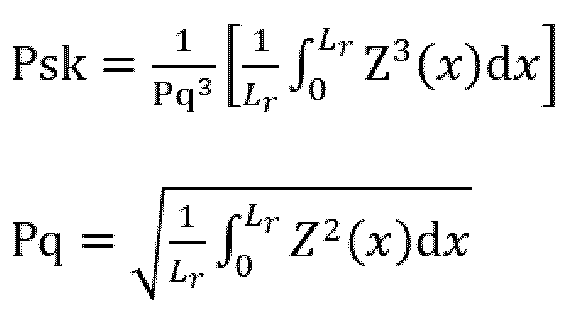
[式中、Pskはスキューネスを表し、Pqは二乗平均平方根高さを表し、Lrは基準長さを表し、Z(x)は基準長さにおいて得られる任意の位置xにおける断面曲線の高さを表す]
で表すことができる。
で表すことができる。
Pskは、歪度を意味し、断面曲線の高さ分布の対称性、すなわち、平均基準線を基準としたときの凸部と凹部の対称性を表す。Psk>0のときは、界面の断面曲線の高さ分布が平均基準線に対して下側に偏っていることを意味し、Psk<0のときは、界面の断面曲線の高さ分布が平均基準線に対して上側に偏っていることを意味し、Psk=0のときは、界面の断面曲線の高さ分布が平均基準線に対して上下に対称(正規分布)であることを意味する。なお、後述の通り、金属層が下側(y座標の負の側)、樹脂フィルム(樹脂層ともいう)が上側(y座標の正の側)になるように解析を行うため、凸部はy軸の正の方向に、すなわち、金属層から樹脂層の方向に突出する部分(金属層上の突出部に相当)を表し、凹部はy軸の負の方向に、すなわち、樹脂層から金属層の方向に突出する部分(金属層上の凹部)を表す。
本発明の一実施形態において、本発明の積層体は、前記断面曲線から得られる最大山高さPp及び最大谷深さPvが、式(II):
|Pp-Pv|≧1.5nm (II)
の関係式を満たすことが好ましい。式(II)を満たすと、積層体の耐力、耐水性や乾燥速度を向上できる。この理由は定かではないが、積層体の界面が式(II)を満たす場合、界面の凹凸が基準線に対して歪な表面性状となり得る。従って、界面での応力集中が生じにくく、また成膜時に前記表面性状の影響を受け、積層体における界面付近の樹脂層の結晶性及び/又は配向性が高まっているためであると推定される。さらに式(II)を満たすと、樹脂フィルム表面の凹凸性状が水を吸収しにくい凹凸構造をとりやすく、また樹脂層の表面(つまり、積層体時の樹脂フィルム側の界面)付近の結晶性及び/又は配向性が高まりやすくいため、積層体の耐水性や乾燥速度を向上できる。
最大山高さPpは、前記断面曲線において、平均基準線(y座標=0の直線)からの高さの最大値を表し、より詳細には、y座標の正に最も大きい凸部の高さを示す。また、最大谷深さPvは、前記断面曲線において、平均基準線からの高さの最小値の絶対値を表し、より詳細には、y座標の負に最も大きい凹部の深さを示す。Pp及びPvはそれぞれ、上記のように積層体の断面曲線を作成し、該断面曲線から求めることができ、例えば実施例に記載の方法により求められる。
本発明の一実施形態において、|Pp-Pv|は、好ましくは3nm以上、よりこの好ましくは5nm以上、さらに好ましくは10nm以上、さらにより好ましくは30nm以上、特に好ましくは50nm以上、特により好ましくは70nm以上、特にさらに好ましくは80nm以上である。また、|Pp-Pv|は、好ましくは1000nm以下、より好ましくは500nm以下、さらに好ましくは400nm以下、さらにより好ましくは300nm以下、特に好ましくは200nm以下、特により好ましくは163nm以下又は160nm以下、特にさらに好ましくは100nm以下又は88nm以下である。|Pp-Pv|が前記下限以上及び/又は前記上限以下であると、積層体における界面の凹凸構造や樹脂層の結晶性及び/又は配向性が、本発明の効果をより一層発現し得る状態になりやすいため、積層体の耐力、耐水性や乾燥速度をより向上できる
本発明の一実施形態において、Ppは、好ましくは100nm以上、より好ましくは200nm以上、さらに好ましくは275nm以上、さらにより好ましくは300nm以上、特に好ましくは330nm以上であり、好ましくは1000nm以下、より好ましくは900nm以下、さらに好ましくは800nm以下、さらにより好ましくは700nm以下、特に好ましくは600nm以下、特により好ましくは550nm以下であり、例えば500nm以下、450nm以下又は400nm以下であってもよい。Ppが上記の範囲内であると、積層体の耐力、耐水性や乾燥速度を高めることができる。
本発明の一実施形態において、Pvは、好ましくは50nm以上、より好ましくは100nm以上、さらに好ましくは200nm以上、さらにより好ましくは250nm以上であり、好ましくは1000nm以下、より好ましくは900nm以下、さらに好ましくは800nm以下、さらにより好ましくは700nm以下、特に好ましくは650nm以下であり、例えば500nm以下、400nm以下、350nm以下、300nm以下又は270nm以下であってもよい。Pvが前記範囲内であると、積層体の耐力、耐水性や乾燥速度を高めることができる。
本発明の一実施形態において、本発明の積層体は、樹脂フィルムと金属層との界面の前記断面曲線から得られるスキューネスPsk及びクルトシスPkuが、式(III):
|Pku/Psk|≦100 式(III)
の関係式を満たすことが好ましい。式(III)を満たすと、積層体の耐力、耐水性や乾燥速度を向上できる。この理由は定かではないが、積層体の界面が式(III)を満たす場合、断面曲線の平均基準線に対する上下対称性が崩れた状態であり、かつ凸部や凹部が尖りすぎない表面性状となり得る。そのため、界面での応力集中が生じにくく、また成膜時に前記表面性状の影響を受け、積層体における界面付近の樹脂層の結晶性及び/又は配向性が高まり、積層体全体として変形に対する強さが高まると考えられる。さらに、式(III)を満たすと、樹脂層表面の凹凸性状が水を吸収しにくい凹凸構造をとりやすくなり、また前述の通り、積層体における界面付近の樹脂層の結晶性及び/又は配向性が高まるため、積層体の耐水性や乾燥速度を向上できると考えられる。
式(III)中のスキューネスPskは上記に述べた通りである。式(III)中のクルトシスPkuは、樹脂フィルムと金属層との界面の断面曲線から得られる高さ分布の鋭さを示す指標である。Pkuは、二乗平均平方根高さPqの四乗により無次元化した基準長さにおいて断面曲線Z(x)の四乗平均を示し、下記式:

[式中、Pkuはクルトシスを表し、Pqは二乗平均平方根高さを表し、Lrは基準長さを表し、Z(x)は基準長さにおいて得られる任意の位置xにおける断面曲線の高さを表す]
で表すことができる。なお、Pqは上記に述べた通りである。
で表すことができる。なお、Pqは上記に述べた通りである。
Pkuは、鋭さの尺度である尖度を意味し、断面曲線の高さ分布の鋭さ(尖り)を表す。Pku>3のときは、尖った凸部や凹部が多いことを意味し、Pku<3のときは、先端がつぶれているような凹凸部が多く、表面が比較的平坦な形状であることを意味し、Pku=3のときは、高さ分布が正規分布であることを意味する。
|Pku/Psk|は、好ましくは90以下、より好ましくは70以下、さらに好ましくは60以下、さらにより好ましくは50以下、特に好ましくは40以下、特により好ましくは35以下である。また、|Pku/Psk|は、好ましくは1.0以上、より好ましくは5.0以上、さらに好ましくは9.0以上、さらにより好ましくは10.0超以上又は11.0以上、特に好ましくは12.0以上、特により好ましくは15.0以上、特にさらに好ましくは20.0以上、特にさらにより好ましくは30.0以上である。|Pku/Psk|が前記上限以下及び/又は前記下限以上であると、積層体における界面の凹凸構造や樹脂層の結晶性及び/又は配向性が、本発明の効果をより一層発現し得る状態になりやすいため、積層体の耐力、耐水性や乾燥速度をより向上できる。
本発明の一実施形態において、Pkuは、好ましくは3.0以上、より好ましくは5.0以上、さらに好ましくは7.0以上であり、例えば9.0以上、10.0以上又は11.0以上であってもよい。またPkuは、好ましくは30以下、より好ましくは20以下、さらに好ましくは18以下、さらにより好ましくは16以下である。Pkuが前記範囲内であると、積層体の耐力、耐水性や乾燥速度を高めることができる。
本発明の積層体において、樹脂フィルムと金属層との界面の前記断面曲線から得られるから得られる最大高さPzは、好ましくは2000nm以下、より好ましくは1500nm以下、さらに好ましくは1200nm以下、さらにより好ましくは1060nm以下であり、例えば1000nm以下、900nm以下、700nm以下であってもよい。最大高さPzは、特に限定されないが、30nm以上、好ましくは50nm以上、より好ましくは100nm以上、さらに好ましくは150nm以上、さらにより好ましくは300nm以上、特に好ましくは550nm以上、特により好ましくは600nm以上である。最大高さPzが前記範囲内であると、積層体の耐力、耐水性や乾燥速度を高めやすく、さらに積層体を用いたFPCの伝送損失を低減することができる。
本発明の積層体において、樹脂フィルムと金属層との界面の前記断面曲線から得られる算術平均高さPaは、特に限定されないが、好ましくは0.50nm以上、より好ましくは1.0nm以上、さらに好ましくは5.0nm以上、さらにより好ましくは10.0nm、特に好ましくは20.0nm以上であり、好ましくは100nm以下、より好ましくは80nm以下、さらに好ましくは60nm以下であり、例えば55nm以下、45nm以下、又は30nm以下であってもよい。算術平均高さPaが前記範囲内であると、積層体の耐力、耐水性や乾燥速度を高めやすく、さらに積層体を用いたFPCの伝送損失を低減することができる。
最大高さPzは、前記断面曲線における高さの最大値(最も高い点から最も低い点までの距離)を表し、算術平均高さPaは、前記断面曲線において、平均基準線からの高低差の平均値を表す。Pz及びPaはそれぞれ、上記のように積層体の断面曲線を作成し、該断面曲線から求めることができ、例えば実施例に記載の方法により求められる。
本明細書では、樹脂層と金属層との界面の前記断面曲線から得られるPsk、Pku、Pz、Pa、Pp、Pv、|Pp-Pv|、|Pku/Psk|等を総称して粗度パラメータということがある。
上記Psk、Pku、Pz、Pa、Pp、及びPvは、それぞれ、SEMにより積層体の厚み方向の断面画像を取得し、該断面画像から樹脂フィルムと金属箔層との界面の断面曲線を作成した際に、該断面曲線から得られるものである。断面曲線は、SEM観察を行い積層体の厚み方向断面のSEM画像を取得した後、得られるSEM画像の画像処理及び解析を行うことにより取得できる。また、鮮明なSEM画像を得るために、SEM観察サンプルの作製工程において、FIB(集束イオンビーム)加工の前処理、FIB加工処理、SEM観察の前処理を順に行うことが好ましい。以下、断面曲線の取得方法の一例を具体的に説明する。
(1)FIB加工
図2(a)に示すように、FIB加工の前処理として、積層体の端面をミクロトームで加工し平滑な厚み方向断面を有する試料を作成し、さらにイオンスパッタ装置を用いて、積層体の金属層表面に白金蒸着を行う。次いで、図2(b)に示すように、積層体の金属層表面に対して垂直方向から集束イオンビームを照射し、ミクロトームで加工した端面中央の一部を、金属層表面側から平面視したときにコの字型になるように切り取り、平滑な断面を作り出す。図2(c)に示すように、加工した断面のうち、上述のミクロトーム加工面に平行な面を観察面とする。
図2(a)に示すように、FIB加工の前処理として、積層体の端面をミクロトームで加工し平滑な厚み方向断面を有する試料を作成し、さらにイオンスパッタ装置を用いて、積層体の金属層表面に白金蒸着を行う。次いで、図2(b)に示すように、積層体の金属層表面に対して垂直方向から集束イオンビームを照射し、ミクロトームで加工した端面中央の一部を、金属層表面側から平面視したときにコの字型になるように切り取り、平滑な断面を作り出す。図2(c)に示すように、加工した断面のうち、上述のミクロトーム加工面に平行な面を観察面とする。
(2)SEM観察
SEM観察の前処理として、イオンスパッタ装置を用いてFIB加工面(観察面)側に白金蒸着を行う。次いで、FIB加工面において、金属層と樹脂層の界面が、取得する画像に対して水平になるよう角度を調整した上でSEM観察を実施する。
SEM観察の前処理として、イオンスパッタ装置を用いてFIB加工面(観察面)側に白金蒸着を行う。次いで、FIB加工面において、金属層と樹脂層の界面が、取得する画像に対して水平になるよう角度を調整した上でSEM観察を実施する。
(3)画像処理
得られるSEM画像(断面画像)を、画像処理ソフト(例えばImage J)により、画像取り込み、スムージング処理、コントラスト調整、二値化(白黒の画像化)、ノイズ除去、輪郭抽出の順に画像処理を実施する。画像取り込みでは、金属層上の凸部が上向きになる方向(取得した積層体界面の画像において、金属層が下側、樹脂層側が上側となる方向)で取り込みを行い、コントラスト調整では、低輝度側に存在する樹脂層由来のヒストグラムの高輝度側端部を最小値、高輝度側に存在する金属層由来のヒストグラムの低輝度側端部を最大値としてコントラスト調整を行う。ノイズ除去過程では、ノイズ輝点を除去後、金属層部分及び樹脂層部分からそれぞれ孤立した部分(例えば、上記二値化により、金属層部分が白、樹脂層部分が黒の場合、金属層から孤立し、樹脂層部に存在する白粒部、樹脂層から孤立し、金属層部に存在する黒粒部)を手動で除去する。輪郭抽出過程では、輪郭曲線を作成後、輪郭曲線の座標をcsv形式で出力する。
得られるSEM画像(断面画像)を、画像処理ソフト(例えばImage J)により、画像取り込み、スムージング処理、コントラスト調整、二値化(白黒の画像化)、ノイズ除去、輪郭抽出の順に画像処理を実施する。画像取り込みでは、金属層上の凸部が上向きになる方向(取得した積層体界面の画像において、金属層が下側、樹脂層側が上側となる方向)で取り込みを行い、コントラスト調整では、低輝度側に存在する樹脂層由来のヒストグラムの高輝度側端部を最小値、高輝度側に存在する金属層由来のヒストグラムの低輝度側端部を最大値としてコントラスト調整を行う。ノイズ除去過程では、ノイズ輝点を除去後、金属層部分及び樹脂層部分からそれぞれ孤立した部分(例えば、上記二値化により、金属層部分が白、樹脂層部分が黒の場合、金属層から孤立し、樹脂層部に存在する白粒部、樹脂層から孤立し、金属層部に存在する黒粒部)を手動で除去する。輪郭抽出過程では、輪郭曲線を作成後、輪郭曲線の座標をcsv形式で出力する。
(4)解析
画像処理により得られる輪郭曲線において、輪郭曲線単位をpixelから距離(nm)に置き直した後、例えばExcelにより、傾き補正及び平均補正を順に行い、金属層と樹脂層の界面の断面曲線を得る。なお、金属層側が下側(y軸の負の側)、樹脂層側が上側(y軸の正の側)になるように粗度パラメータを算出する。
例えば、図3は補正前及び各補正後の輪郭曲線を説明するための図であり、補正前の輪郭曲線が7であり、該輪郭曲線7に傾き補正を行った傾き補正後の輪郭曲線が8であり、該輪郭曲線8に、さらに平均補正を行った傾き補正及び平均補正後の輪郭曲線(断面曲線ともいう)が9である。傾き補正は、輪郭曲線の回帰直線の傾きaを算出し、各座標(x,y)においてy’=y-x×aを求め、(x,y’)として置き直す。また、平均値補正は、全座標のy’値を使用して平均値bを算出し、各座標(x,y’)においてy’’=y’-bを求め、(x,y’’)と置き直す。ここで、上記解析により得た断面曲線は、y”(x)で表される。
得られる断面曲線y”(x)を用いて、下記の式からPq及びPskを求めることができる。なお、断面曲線、Pq及びPskは、例えば実施例に記載の方法により求めることができる。
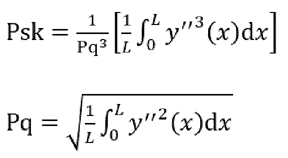
[式中、Pskはスキューネスを表し、Pqは二乗平均平方根高さを表し、Lは最大x値-最小x値(すなわち、断面曲線の端から端までの距離;基準長さ)を表し、y’’(x)は断面曲線を表す]
Psk以外の他の粗度パラメータも同様に、断面曲線y”(x)を用いることで算出できる。
本発明の一実施形態において、樹脂フィルムがPI系フィルムである場合、本発明の積層体は、比較的低いイミド化温度で成膜可能であり、金属層上でPI系樹脂前駆体塗膜の熱イミド化を行うことによって金属層が銅層(好ましくは銅箔層)である積層体を製造しても、銅層表面の劣化を抑制しながら十分に高い耐力や低いDfを実現できる。そのため、本発明の積層体は、接着層がなくても優れた高周波特性を有する。
本発明の一実施形態において、本発明の積層体の0.2%耐力は、好ましくは66MPa以上、より好ましくは70MPa以上、さらに好ましくは72MPa以上、さらにより好ましくは75MPa以上、特に好ましくは80MPa以上、特により好ましくは85MPa以上、特にさらに好ましくは87MPa以上、極めて好ましくは90MPa以上であり、例えば92MPa以上又は95MPa以上であってもよい。積層体の0.2%耐力が前記下限以上であると、変形に対する強さに優れ、積層体を含むFPC等として使用する際の塑性変形に起因した電気的特性の劣化を抑制できる。また、本発明の積層体の0.2%耐力の上限は特に限定されないが、例えば300MPa以下、好ましくは150MPa以下である。積層体の0.2%耐力は、温度25℃、相対湿度50%、チャック間距離50mm、引張速度20mm/分の条件で引張試験機を用いて得た応力-歪曲線(以下、S-S曲線ともいう)において、歪0における接線を歪方向に0.2%平行移動し、平行移動した直線がS-S曲線と交わる応力値を示す。0.2%耐力は、例えば実施例に記載の方法により求めることができる。
[積層体の製造方法]
本発明の積層体の製造方法は、金属層の前記樹脂フィルムと接する面が式(I)を満たし、樹脂フィルムの少なくとも一方の面に金属層が直接積層可能な方法であれば特に限定されないが、例えばメッキ処理により樹脂フィルム上に金属層を形成する方法;金属層の表面上に、樹脂フィルムを構成する樹脂の溶液又は該樹脂の前駆体の溶液を塗布及び乾燥する製造方法;樹脂フィルムと金属層とを貼り合せる方法などが挙げられる。
本発明の積層体の製造方法は、金属層の前記樹脂フィルムと接する面が式(I)を満たし、樹脂フィルムの少なくとも一方の面に金属層が直接積層可能な方法であれば特に限定されないが、例えばメッキ処理により樹脂フィルム上に金属層を形成する方法;金属層の表面上に、樹脂フィルムを構成する樹脂の溶液又は該樹脂の前駆体の溶液を塗布及び乾燥する製造方法;樹脂フィルムと金属層とを貼り合せる方法などが挙げられる。
本発明の一実施形態において、メッキ処理による積層体の製造方法としては、例えば、<樹脂フィルムの製造方法>の項に記載のように、キャスト成形や押出成形等によって樹脂フィルムを作製後、該樹脂フィルム表面に金属メッキを行うことにより、樹脂フィルム表面に金属層(金属メッキ層)を設ける方法が挙げられる。金属メッキ層は、積層体の導電性の観点から、銅メッキ層又は銅合金メッキ層が好ましく、銅メッキ層がより好ましい。この場合、支持基材の樹脂フィルムと接する側の表面は、上記「金属表面の表面粗さパラメータ」と同様の表面性状を満たすことが好ましい。樹脂フィルムがPI系フィルムである場合、PI系樹脂前駆体溶液の支持基材への塗布方法や予備乾燥方法、静置方法及びイミド化の加熱条件等は、後述する金属層を支持基材に用いた時と同様の条件を採用することができる。
本発明の別の一実施形態において、樹脂フィルム表面にエンボス加工、マット加工、ヘアライン加工、ブラスト加工、デスミア処理等を行い、凹凸を付けた後、該樹脂フィルム表面に金属メッキを行い、樹脂フィルム表面に金属層(金属メッキ層)を設けることで積層体を製造することもできる。
本発明の別の一実施形態において、樹脂フィルム表面にエンボス加工、マット加工、ヘアライン加工、ブラスト加工、デスミア処理等を行い、凹凸を付けた後、該樹脂フィルム表面に金属メッキを行い、樹脂フィルム表面に金属層(金属メッキ層)を設けることで積層体を製造することもできる。
本発明の好適な実施形態において、樹脂フィルムがPI系フィルムである場合、支持基材として金属層を使用し、金属層の表面上に直接樹脂フィルムを形成する方法としては、例えば金属層の表面上に、対応するPI系樹脂前駆体の溶液を塗布及び予備乾燥して塗膜を得る工程(塗工及び予備乾燥工程ともいう);得られた塗膜を静置する工程(静置工程ともいう)、並びに塗膜を加熱してPI系樹脂をイミド化する工程(イミド化工程ともいう)を含む方法が挙げられる。なお、前記塗膜はPI系フィルムが単層フィルムである場合は単層塗膜であり、積層フィルムである場合は多層塗膜である。なお、積層体の製造において、静置工程を含んでいなくてもよいが、静置工程を含むと、塗膜全体に溶媒が十分に残存した状態、又は樹脂層間が良く馴染んだ状態となりやすいため、イミド化時まで樹脂分子の自由度が高くなり、PI系樹脂含有層の間で樹脂分子の状態が一定となりやすい。そのため、積層体の耐力等の機械的強度を向上できる。PI系フィルムのもう一方の面にも金属層を形成する場合には、熱ラミネートや熱プレスなどの熱圧着により金属層をPI系フィルムの他方の面に貼り合わせる方法が挙げられる。
(PI系樹脂前駆体の調製)
PI系樹脂前駆体は、テトラカルボン酸化合物とジアミン化合物とを反応させて得ることができる。PI系樹脂前駆体の合成に用いられるテトラカルボン酸化合物としては、例えば、芳香族テトラカルボン酸二無水物等の芳香族テトラカルボン酸化合物;及び脂肪族テトラカルボン酸二無水物等の脂肪族テトラカルボン酸化合物等が挙げられる。テトラカルボン酸化合物は、単独で用いてもよいし、2種以上を組合せて用いてもよい。テトラカルボン酸化合物は、二無水物の他、酸クロリド化合物等のテトラカルボン酸化合物類縁体であってもよい。
PI系樹脂前駆体は、テトラカルボン酸化合物とジアミン化合物とを反応させて得ることができる。PI系樹脂前駆体の合成に用いられるテトラカルボン酸化合物としては、例えば、芳香族テトラカルボン酸二無水物等の芳香族テトラカルボン酸化合物;及び脂肪族テトラカルボン酸二無水物等の脂肪族テトラカルボン酸化合物等が挙げられる。テトラカルボン酸化合物は、単独で用いてもよいし、2種以上を組合せて用いてもよい。テトラカルボン酸化合物は、二無水物の他、酸クロリド化合物等のテトラカルボン酸化合物類縁体であってもよい。
テトラカルボン酸化合物としては、例えば、式(A1)で表されるテトラカルボン酸無水物、式(A2)で表されるテトラカルボン酸無水物、式(A3)で表されるテトラカルボン酸無水物が挙げられ、当該分野で公知のテトラカルボン酸化合物を適宜選択して用いることができる。
そのようなテトラカルボン酸化合物としては、例えば、無水ピロメリット酸(以下、PMDAと記載することがある)、4,4’-(4,4’-イソプロピリデンジフェノキシ)ジフタル酸無水物(以下、BPADAと記載することがある)、1,4,5,8-ナフタレンテトラカルボン酸二無水物、3,3’,4,4’-ビフェニルテトラカルボン酸二無水物(以下、BPDAと記載することがある)、4,4’-(ヘキサフルオロイソプロピリデン)ジフタル酸二無水物(以下、6FDAと記載することがある)、4,4’-オキシジフタル酸二無水物(以下、ODPAと記載することがある)、2,2’,3,3’-、2,3,3’,4’-又は3,3’,4,4’-ベンゾフェノンテトラカルボン酸二無水物、2,3’,3,4’-ビフェニルテトラカルボン酸二無水物、2,2’,3,3’-ビフェニルテトラカルボン酸二無水物、p-フェニレンビス(トリメリット酸モノエステル酸二無水物)(以下、TAHQと記載することがある)、無水トリメリット酸と2,2’,3,3’,5,5’-ヘキサメチル-4,4’-ビフェノールとのエステル化物(以下、TMPBPと記載することがある)、4,4’-ビス(1,3-ジオキソ-1,3-ジヒドロイソベンゾフラン-5-イルカルボニルオキシ)ビフェニル(以下、BP-TMEと記載することがある)、2,3’,3,4’-ジフェニルエーテルテトラカルボン酸二無水物、ビス(2,3-ジカルボキシフェニル)エーテル二無水物、3,3”,4,4”-p-テルフェニルテトラカルボン酸二無水物、2,3,3”,4”-p-テルフェニルテトラカルボン酸二無水物、2,2”,3,3”-p-テルフェニルテトラカルボン酸二無水物、2,2-ビス(2,3-ジカルボキシフェニル)-プロパン二無水物、2,2-ビス(3,4-ジカルボキシフェニル)-プロパン二無水物、ビス(2,3-ジカルボキシフェニル)メタン二無水物、ビス(3,4-ジカルボキシフェニル)メタン二無水物、1,1-ビス(2,3-ジカルボキシフェニル)エタン二無水物、1,1-ビス(3,4-ジカルボキシフェニル)エタン二無水物、1,2,7,8-、1,2,6,7-フェナンスレン-テトラカルボン酸二無水物、1,2,9,10-フェナンスレン-テトラカルボン酸二無水物、2,2-ビス(3,4-ジカルボキシフェニル)テトラフルオロプロパン二無水物、1,2,4,5-シクロヘキサンテトラカルボン酸二無水物(以下、HPMDAと記載することがある)、2,3,5,6-シクロヘキサンテトラカルボン酸二無水物、2,3,6,7-ナフタレンテトラカルボン酸二無水物、1,2,5,6-ナフタレンテトラカルボン酸二無水物、シクロペンタン-1,2,3,4-テトラカルボン酸二無水物、4,4’-ビス(2,3-ジカルボキシフェノキシ)ジフェニルメタン二無水物、1,2,3,4-シクロブタンテトラカルボン酸二無水物(以下、CBDAと記載することがある)、ノルボルナン-2-スピロ-α’-スピロ-2”-ノルボルナン-5,5’,6,6’-テトラカルボン酸無水物、p-フェニレンビス(トリメリテート無水物)、3,3’,4,4’-ジフェニルスルホンテトラカルボン酸二無水物、2,3,6,7-アントラセンテトラカルボン酸二無水物、4,8-ジメチル-1,2,3,5,6,7-ヘキサヒドロナフタレン-1,2,5,6-テトラカルボン酸二無水物、2,6-ジクロロナフタレン-1,4,5,8-テトラカルボン酸二無水物、2,7-ジクロロナフタレン-1,4,5,8-テトラカルボン酸二無水物、2,3,6,7-テトラクロロナフタレン-1,4,5,8-テトラカルボン酸二無水物、2,3,6,7-テトラクロロナフタレン-2,3,6,7-テトラカルボン酸二無水物、1,4,5,8-テトラクロロナフタレン-1,4,5,8-テトラカルボン酸二無水物、1,4,5,8-テトラクロロナフタレン-2,3,6,7-テトラカルボン酸二無水物、2,3,8,9-ペリレン-テトラカルボン酸二無水物、3,4,9,10-ペリレン-テトラカルボン酸二無水物、4,5,10,11-ペリレン-テトラカルボン酸二無水物、5,6,11,12-ペリレン-テトラカルボン酸二無水物、ピラジン-2,3,5,6-テトラカルボン酸二無水物、ピロリジン-2,3,4,5-テトラカルボン酸二無水物、チオフェン-2,3,4,5-テトラカルボン酸二無水物、ビス(2,3-ジカルボキシフェニル)スルホン二無水物、ビス(3,4-ジカルボキシフェニル)スルホン二無水物などが挙げられる。中でも、得られる積層体の耐力の向上、DfやCTEの低減等の観点から、BPDA、PMDA、TAHQ及び/又はBP-TMEを組み合わせて用いることが好ましい。これらのテトラカルボン酸化合物は単独又は二種以上組合せて使用できる。
そのようなテトラカルボン酸化合物としては、例えば、無水ピロメリット酸(以下、PMDAと記載することがある)、4,4’-(4,4’-イソプロピリデンジフェノキシ)ジフタル酸無水物(以下、BPADAと記載することがある)、1,4,5,8-ナフタレンテトラカルボン酸二無水物、3,3’,4,4’-ビフェニルテトラカルボン酸二無水物(以下、BPDAと記載することがある)、4,4’-(ヘキサフルオロイソプロピリデン)ジフタル酸二無水物(以下、6FDAと記載することがある)、4,4’-オキシジフタル酸二無水物(以下、ODPAと記載することがある)、2,2’,3,3’-、2,3,3’,4’-又は3,3’,4,4’-ベンゾフェノンテトラカルボン酸二無水物、2,3’,3,4’-ビフェニルテトラカルボン酸二無水物、2,2’,3,3’-ビフェニルテトラカルボン酸二無水物、p-フェニレンビス(トリメリット酸モノエステル酸二無水物)(以下、TAHQと記載することがある)、無水トリメリット酸と2,2’,3,3’,5,5’-ヘキサメチル-4,4’-ビフェノールとのエステル化物(以下、TMPBPと記載することがある)、4,4’-ビス(1,3-ジオキソ-1,3-ジヒドロイソベンゾフラン-5-イルカルボニルオキシ)ビフェニル(以下、BP-TMEと記載することがある)、2,3’,3,4’-ジフェニルエーテルテトラカルボン酸二無水物、ビス(2,3-ジカルボキシフェニル)エーテル二無水物、3,3”,4,4”-p-テルフェニルテトラカルボン酸二無水物、2,3,3”,4”-p-テルフェニルテトラカルボン酸二無水物、2,2”,3,3”-p-テルフェニルテトラカルボン酸二無水物、2,2-ビス(2,3-ジカルボキシフェニル)-プロパン二無水物、2,2-ビス(3,4-ジカルボキシフェニル)-プロパン二無水物、ビス(2,3-ジカルボキシフェニル)メタン二無水物、ビス(3,4-ジカルボキシフェニル)メタン二無水物、1,1-ビス(2,3-ジカルボキシフェニル)エタン二無水物、1,1-ビス(3,4-ジカルボキシフェニル)エタン二無水物、1,2,7,8-、1,2,6,7-フェナンスレン-テトラカルボン酸二無水物、1,2,9,10-フェナンスレン-テトラカルボン酸二無水物、2,2-ビス(3,4-ジカルボキシフェニル)テトラフルオロプロパン二無水物、1,2,4,5-シクロヘキサンテトラカルボン酸二無水物(以下、HPMDAと記載することがある)、2,3,5,6-シクロヘキサンテトラカルボン酸二無水物、2,3,6,7-ナフタレンテトラカルボン酸二無水物、1,2,5,6-ナフタレンテトラカルボン酸二無水物、シクロペンタン-1,2,3,4-テトラカルボン酸二無水物、4,4’-ビス(2,3-ジカルボキシフェノキシ)ジフェニルメタン二無水物、1,2,3,4-シクロブタンテトラカルボン酸二無水物(以下、CBDAと記載することがある)、ノルボルナン-2-スピロ-α’-スピロ-2”-ノルボルナン-5,5’,6,6’-テトラカルボン酸無水物、p-フェニレンビス(トリメリテート無水物)、3,3’,4,4’-ジフェニルスルホンテトラカルボン酸二無水物、2,3,6,7-アントラセンテトラカルボン酸二無水物、4,8-ジメチル-1,2,3,5,6,7-ヘキサヒドロナフタレン-1,2,5,6-テトラカルボン酸二無水物、2,6-ジクロロナフタレン-1,4,5,8-テトラカルボン酸二無水物、2,7-ジクロロナフタレン-1,4,5,8-テトラカルボン酸二無水物、2,3,6,7-テトラクロロナフタレン-1,4,5,8-テトラカルボン酸二無水物、2,3,6,7-テトラクロロナフタレン-2,3,6,7-テトラカルボン酸二無水物、1,4,5,8-テトラクロロナフタレン-1,4,5,8-テトラカルボン酸二無水物、1,4,5,8-テトラクロロナフタレン-2,3,6,7-テトラカルボン酸二無水物、2,3,8,9-ペリレン-テトラカルボン酸二無水物、3,4,9,10-ペリレン-テトラカルボン酸二無水物、4,5,10,11-ペリレン-テトラカルボン酸二無水物、5,6,11,12-ペリレン-テトラカルボン酸二無水物、ピラジン-2,3,5,6-テトラカルボン酸二無水物、ピロリジン-2,3,4,5-テトラカルボン酸二無水物、チオフェン-2,3,4,5-テトラカルボン酸二無水物、ビス(2,3-ジカルボキシフェニル)スルホン二無水物、ビス(3,4-ジカルボキシフェニル)スルホン二無水物などが挙げられる。中でも、得られる積層体の耐力の向上、DfやCTEの低減等の観点から、BPDA、PMDA、TAHQ及び/又はBP-TMEを組み合わせて用いることが好ましい。これらのテトラカルボン酸化合物は単独又は二種以上組合せて使用できる。
PI系樹脂前駆体の合成に用いられるジアミン化合物としては、例えば、脂肪族ジアミン、芳香族ジアミン及びこれらの混合物が挙げられる。なお、本実施形態において「芳香族ジアミン」とは、芳香環を有するジアミンを表し、その構造の一部に脂肪族基又はその他の置換基を含んでいてもよい。この芳香環は単環でも縮合環でもよく、ベンゼン環、ナフタレン環、アントラセン環及びフルオレン環等が例示されるが、これらに限定されるわけではない。これらの中でも、好ましくはベンゼン環である。また「脂肪族ジアミン」とは、脂肪族基を有するジアミンを表し、その構造の一部にその他の置換基を含んでいてもよいが、芳香環は有しない。
ジアミン化合物としては、例えば、式(B1)で表されるジアミン、式(B2)で表されるジアミン、式(2)で表されるジアミン等が挙げられ、当該分野で公知のジアミン化合物を適宜選択して用いることができる。
そのようなジアミン化合物としては、例えば、1,4-ジアミノシクロヘキサン、4,4’-ジアミノ-2,2’-ジメチルビフェニル(以下、m-Tbと記載することがある)、4,4’-ジアミノ-3,3’-ジメチルビフェニル、2,2’-ビス(トリフルオロメチル)-4,4’-ジアミノジフェニル(以下、TFMBと記載することがある)、4,4’-ジアミノジフェニルエーテル、1,3-ビス(3-アミノフェノキシ)ベンゼン(以下、1,3-APBと記載することがある)、1,4-ビス(4-アミノフェノキシ)ベンゼン(以下、TPE-Qと記載することがある)、1,3-ビス(4-アミノフェノキシ)ベンゼン(以下、TPE-Rと記載することがある)、2,2-ビス[4-(4-アミノフェノキシ)フェニル]プロパン(以下、BAPPと記載することがある)、2,2’-ジメチル-4,4’-ジアミノビフェニル、3,3’-ジヒドロキシ-4,4’-ジアミノビフェニル、2,2-ビス-[4-(3-アミノフェノキシ)フェニル]プロパン、ビス[4-(4-アミノフェノキシ)]ビフェニル、ビス[4-(3-アミノフェノキシ)ビフェニル、ビス[1-(4-アミノフェノキシ)]ビフェニル、ビス[1-(3-アミノフェノキシ)]ビフェニル、ビス[4-(4-アミノフェノキシ)フェニル]メタン、ビス[4-(3-アミノフェノキシ)フェニル]メタン、ビス[4-(4-アミノフェノキシ)フェニル]エーテル、ビス[4-(3-アミノフェノキシ)フェニル]エーテル、ビス[4-(4-アミノフェノキシ)]ベンゾフェノン、ビス[4-(3-アミノフェノキシ)]ベンゾフェノン、2,2-ビス-[4-(4-アミノフェノキシ)フェニル]ヘキサフルオロプロパン、2,2-ビス-[4-(3-アミノフェノキシ)フェニル]ヘキサフルオロプロパン、4,4’-メチレンジ-o-トルイジン、4,4’-メチレンジ-2,6-キシリジン、4,4’-メチレン-2,6-ジエチルアニリン、4,4’-メチレンジアニリン、3,3’-メチレンジアニリン、4,4’-ジアミノジフェニルプロパン、3,3’-ジアミノジフェニルプロパン、4,4’-ジアミノジフェニルエタン、3,3’-ジアミノジフェニルエタン、4,4’-ジアミノジフェニルメタン、3,3’-ジアミノジフェニルメタン、3,3-ジアミノジフェニルエーテル、3,4’-ジアミノジフェニルエーテル、ベンジジン、3,3’-ジアミノビフェニル、3,3’-ジメトキシベンジジン、4,4”-ジアミノ-p-テルフェニル、3,3”-ジアミノ-p-テルフェニル、m-フェニレンジアミン、p-フェニレンジアミン(以下、p-PDAと記載することがある)、レゾルシノール-ビス(3-アミノフェニル)エーテル、4,4’-[1,4-フェニレンビス(1-メチルエチリデン)]ビスアニリン、4,4’-[1,3-フェニレンビス(1-メチルエチリデン)]ビスアニリン、ビス(p-アミノシクロヘキシル)メタン、ビス(p-β-アミノ-tert-ブチルフェニル)エーテル、ビス(p-β-メチル-δ-アミノペンチル)ベンゼン、p-ビス(2-メチル-4-アミノペンチル)ベンゼン、p-ビス(1,1-ジメチル-5-アミノペンチル)ベンゼン、1,5-ジアミノナフタレン、2,6-ジアミノナフタレン、2,4-ビス(β-アミノ-tert-ブチル)トルエン、2,4-ジアミノトルエン、m-キシレン-2,5-ジアミン、p-キシレン-2,5-ジアミン、m-キシリレンジアミン、p-キシリレンジアミン、ピペラジン、4,4’-ジアミノ-2,2’-ビス(トリフルオロメチル)ビシクロヘキサン、4,4’-ジアミノジシクロヘキシルメタン、4,4”-ジアミノ-p-ターフェニル、ビス(4-アミノフェニル)テレフタレート、1,4-ビス(4-アミノフェノキシ)-2,5-ジ-tert-ブチルベンゼン、4,4’-(1,3-フェニレンジイソプロピリデン)ビスアニリン、1,4-ビス[2-(4-アミノフェニル)-2-プロピル]ベンゼン、2,4-ジアミノ-3,5-ジエチルトルエン、2,6-ジアミノ-3,5-ジエチルトルエン、4,4’-ビス(3-アミノフェノキシ)ビフェニル、4,4’-(ヘキサフルオロプロピリデン)ジアニリン、1,2-ジアミノエタン、1,3-ジアミノプロパン、1,4-ジアミノブタン、1,5-ジアミノペンタン、1,6-ジアミノヘキサン、1,2-ジアミノプロパン、1,2-ジアミノブタン、1,3-ジアミノブタン、2-メチル-1,2-ジアミノプロパン、2-メチル-1,3-ジアミノプロパン、1,3-ビス(アミノメチル)シクロヘキサン、1,4-ビス(アミノメチル)シクロヘキサン、ノルボルナンジアミン、2’-メトキシ-4,4’-ジアミノベンズアニリド、4,4’-ジアミノベンズアニリド、ビス[4-(4-アミノフェノキシ)フェニル]スルホン、ビス[4-(3-アミノフェノキシ)フェニル]スルホン、9,9-ビス[4-(4-アミノフェノキシ)フェニル]フルオレン、9,9-ビス[4-(3-アミノフェノキシ)フェニル]フルオレン、4,4’-ジアミノジフェニルスルフィド、3,3’-ジアミノジフェニルスルフィド、4,4’-ジアミノジフェニルスルホン、3,3’-ジアミノジフェニルスルホン、2,5-ジアミノ-1,3,4-オキサジアゾール、ビス[4,4’-(4-アミノフェノキシ)]ベンズアニリド、ビス[4,4’-(3-アミノフェノキシ)]ベンズアニリド、2,6-ジアミノピリジン、2,5-ジアミノピリジンなどが挙げられる。中でも、得られる積層体の耐力の向上、DfやCTEの低減等の観点から、m-Tb、BAPP、TPE-Q、1,3-ビス(4-アミノフェノキシ)ベンゼン及び/又はTPE-Rを組み合わせて用いることが好ましい。ジアミン化合物は単独又は二種以上組合せて使用できる。
そのようなジアミン化合物としては、例えば、1,4-ジアミノシクロヘキサン、4,4’-ジアミノ-2,2’-ジメチルビフェニル(以下、m-Tbと記載することがある)、4,4’-ジアミノ-3,3’-ジメチルビフェニル、2,2’-ビス(トリフルオロメチル)-4,4’-ジアミノジフェニル(以下、TFMBと記載することがある)、4,4’-ジアミノジフェニルエーテル、1,3-ビス(3-アミノフェノキシ)ベンゼン(以下、1,3-APBと記載することがある)、1,4-ビス(4-アミノフェノキシ)ベンゼン(以下、TPE-Qと記載することがある)、1,3-ビス(4-アミノフェノキシ)ベンゼン(以下、TPE-Rと記載することがある)、2,2-ビス[4-(4-アミノフェノキシ)フェニル]プロパン(以下、BAPPと記載することがある)、2,2’-ジメチル-4,4’-ジアミノビフェニル、3,3’-ジヒドロキシ-4,4’-ジアミノビフェニル、2,2-ビス-[4-(3-アミノフェノキシ)フェニル]プロパン、ビス[4-(4-アミノフェノキシ)]ビフェニル、ビス[4-(3-アミノフェノキシ)ビフェニル、ビス[1-(4-アミノフェノキシ)]ビフェニル、ビス[1-(3-アミノフェノキシ)]ビフェニル、ビス[4-(4-アミノフェノキシ)フェニル]メタン、ビス[4-(3-アミノフェノキシ)フェニル]メタン、ビス[4-(4-アミノフェノキシ)フェニル]エーテル、ビス[4-(3-アミノフェノキシ)フェニル]エーテル、ビス[4-(4-アミノフェノキシ)]ベンゾフェノン、ビス[4-(3-アミノフェノキシ)]ベンゾフェノン、2,2-ビス-[4-(4-アミノフェノキシ)フェニル]ヘキサフルオロプロパン、2,2-ビス-[4-(3-アミノフェノキシ)フェニル]ヘキサフルオロプロパン、4,4’-メチレンジ-o-トルイジン、4,4’-メチレンジ-2,6-キシリジン、4,4’-メチレン-2,6-ジエチルアニリン、4,4’-メチレンジアニリン、3,3’-メチレンジアニリン、4,4’-ジアミノジフェニルプロパン、3,3’-ジアミノジフェニルプロパン、4,4’-ジアミノジフェニルエタン、3,3’-ジアミノジフェニルエタン、4,4’-ジアミノジフェニルメタン、3,3’-ジアミノジフェニルメタン、3,3-ジアミノジフェニルエーテル、3,4’-ジアミノジフェニルエーテル、ベンジジン、3,3’-ジアミノビフェニル、3,3’-ジメトキシベンジジン、4,4”-ジアミノ-p-テルフェニル、3,3”-ジアミノ-p-テルフェニル、m-フェニレンジアミン、p-フェニレンジアミン(以下、p-PDAと記載することがある)、レゾルシノール-ビス(3-アミノフェニル)エーテル、4,4’-[1,4-フェニレンビス(1-メチルエチリデン)]ビスアニリン、4,4’-[1,3-フェニレンビス(1-メチルエチリデン)]ビスアニリン、ビス(p-アミノシクロヘキシル)メタン、ビス(p-β-アミノ-tert-ブチルフェニル)エーテル、ビス(p-β-メチル-δ-アミノペンチル)ベンゼン、p-ビス(2-メチル-4-アミノペンチル)ベンゼン、p-ビス(1,1-ジメチル-5-アミノペンチル)ベンゼン、1,5-ジアミノナフタレン、2,6-ジアミノナフタレン、2,4-ビス(β-アミノ-tert-ブチル)トルエン、2,4-ジアミノトルエン、m-キシレン-2,5-ジアミン、p-キシレン-2,5-ジアミン、m-キシリレンジアミン、p-キシリレンジアミン、ピペラジン、4,4’-ジアミノ-2,2’-ビス(トリフルオロメチル)ビシクロヘキサン、4,4’-ジアミノジシクロヘキシルメタン、4,4”-ジアミノ-p-ターフェニル、ビス(4-アミノフェニル)テレフタレート、1,4-ビス(4-アミノフェノキシ)-2,5-ジ-tert-ブチルベンゼン、4,4’-(1,3-フェニレンジイソプロピリデン)ビスアニリン、1,4-ビス[2-(4-アミノフェニル)-2-プロピル]ベンゼン、2,4-ジアミノ-3,5-ジエチルトルエン、2,6-ジアミノ-3,5-ジエチルトルエン、4,4’-ビス(3-アミノフェノキシ)ビフェニル、4,4’-(ヘキサフルオロプロピリデン)ジアニリン、1,2-ジアミノエタン、1,3-ジアミノプロパン、1,4-ジアミノブタン、1,5-ジアミノペンタン、1,6-ジアミノヘキサン、1,2-ジアミノプロパン、1,2-ジアミノブタン、1,3-ジアミノブタン、2-メチル-1,2-ジアミノプロパン、2-メチル-1,3-ジアミノプロパン、1,3-ビス(アミノメチル)シクロヘキサン、1,4-ビス(アミノメチル)シクロヘキサン、ノルボルナンジアミン、2’-メトキシ-4,4’-ジアミノベンズアニリド、4,4’-ジアミノベンズアニリド、ビス[4-(4-アミノフェノキシ)フェニル]スルホン、ビス[4-(3-アミノフェノキシ)フェニル]スルホン、9,9-ビス[4-(4-アミノフェノキシ)フェニル]フルオレン、9,9-ビス[4-(3-アミノフェノキシ)フェニル]フルオレン、4,4’-ジアミノジフェニルスルフィド、3,3’-ジアミノジフェニルスルフィド、4,4’-ジアミノジフェニルスルホン、3,3’-ジアミノジフェニルスルホン、2,5-ジアミノ-1,3,4-オキサジアゾール、ビス[4,4’-(4-アミノフェノキシ)]ベンズアニリド、ビス[4,4’-(3-アミノフェノキシ)]ベンズアニリド、2,6-ジアミノピリジン、2,5-ジアミノピリジンなどが挙げられる。中でも、得られる積層体の耐力の向上、DfやCTEの低減等の観点から、m-Tb、BAPP、TPE-Q、1,3-ビス(4-アミノフェノキシ)ベンゼン及び/又はTPE-Rを組み合わせて用いることが好ましい。ジアミン化合物は単独又は二種以上組合せて使用できる。
なお、前記PI系樹脂前駆体は、得られるPI系フィルムの各種物性を損なわない範囲で、上記のPI系樹脂前駆体合成に用いられるテトラカルボン酸化合物に加えて、他のテトラカルボン酸、ジカルボン酸及びトリカルボン酸並びにそれらの無水物及び誘導体をさらに反応させたものであってもよい。
他のテトラカルボン酸としては、上記テトラカルボン酸化合物の無水物の水付加体が挙げられる。
ジカルボン酸化合物としては、芳香族ジカルボン酸、脂肪族ジカルボン酸及びそれらの類縁の酸クロリド化合物、酸無水物等が挙げられ、2種以上を組合せて用いてもよい。具体例としては、テレフタル酸;イソフタル酸;ナフタレンジカルボン酸;4,4’-ビフェニルジカルボン酸;3,3’-ビフェニルジカルボン酸;炭素数8以下である鎖式炭化水素のジカルボン酸化合物及び2つの安息香酸が単結合、-O-、-CH2-、-C(CH3)2-、-C(CF3)2-、-SO2-又はフェニレン基で連結された化合物並びに、それらの酸クロリド化合物が挙げられる。
トリカルボン酸化合物としては、芳香族トリカルボン酸、脂肪族トリカルボン酸及びそれらの類縁の酸クロリド化合物、酸無水物等が挙げられ、2種以上を組合せて用いてもよい。具体例としては、1,2,4-ベンゼントリカルボン酸の無水物;2,3,6-ナフタレントリカルボン酸-2,3-無水物;フタル酸無水物と安息香酸とが単結合、-O-、-CH2-、-C(CH3)2-、-C(CF3)2-、-SO2-又はフェニレン基で連結された化合物が挙げられる。
PI系樹脂前駆体の製造において、ジアミン化合物、テトラカルボン酸化合物、ジカルボン酸化合物及びトリカルボン酸化合物の使用量は、所望とするPI系樹脂前駆体の各構成単位の比率に応じて適宜選択できる。
本発明において、テトラカルボン酸化合物の総量1モルに対するジアミン化合物の総使用モル数をアミン比として定義する。本発明の好適な一実施形態においては、アミン比は、テトラカルボン酸化合物の総量1モルに対して、好ましくは0.90モル以上であり、好ましくは0.999モル以下である。また、別の一実施形態においては、アミン比は、テトラカルボン酸化合物の総量1モルに対して、好ましくは1.001モル以上であり、好ましくは1.10モル以下である。
本発明の一実施形態において、アミン比が1以下である場合、アミン比は好ましくは0.90モル以上0.999モル以下、より好ましくは0.95モル以上0.997モル以下、さらに好ましくは0.97モル以上0.995モル以下である。
本発明の一実施形態において、アミン比が1以上である場合、アミン比は好ましくは1.001モル以上1.10モル以下、より好ましくは1.002モル以上1.06モル以下、さらに好ましくは1.003モル以上1.05モル以下である
アミン比が1.0モルに近いと、合成時に急激に分子量が増大する傾向があり、1.0モルから大きく離れると得られるPI系樹脂の分子量が低下しやすい傾向がある。分子量が急激に増大すると、合成マスの中で不均一に成長して、PI系樹脂前駆体から得られるPI系樹脂の物性が安定しにくい傾向がある。一方、分子量が低すぎると機械物性が低下する傾向がある。
ジアミン化合物とテトラカルボン酸化合物との反応温度は、好ましくは50℃以下、より好ましくは40℃以下、さらに好ましくは30℃以下である。また、ジアミン化合物とテトラカルボン酸化合物との反応温度は、好ましくは5℃以上、より好ましくは10℃以上、さらに好ましくは15℃以上である。反応温度が前記上限及び下限の範囲内であると、本発明の効果を得やすく、また、反応速度を高め、重合時間を短くできる傾向にある。反応時間は特に限定されず、例えば0.5~36時間程度、好ましくは1~24時間であってもよい。
ジアミン化合物とテトラカルボン酸化合物との反応は、溶媒中で行うことが好ましい。溶媒としては、反応に影響を与えない限り特に限定されないが、例えば、水、メタノール、エタノール、エチレングリコール、イソプロピルアルコール、プロピレングリコール、エチレングリコールメチルエーテル、エチレングリコールブチルエーテル、1-メトキシ-2-プロパノール、2-ブトキシエタノール、プロピレングリコールモノメチルエーテル等のアルコール系溶媒;フェノール、クレゾール等のフェノール系溶媒;酢酸エチル、酢酸ブチル、エチレングリコールメチルエーテルアセテート、プロピレングリコールメチルエーテルアセテート、乳酸エチル等のエステル系溶媒;γ-ブチロラクトン(以下、GBLと記載することがある)、γ-バレロラクトン等のラクトン系溶媒;アセトン、メチルエチルケトン、シクロペンタノン、シクロヘキサノン、2-ヘプタノン、メチルイソブチルケトン等のケトン系溶媒;ペンタン、ヘキサン、ヘプタン等の脂肪族炭化水素溶媒;エチルシクロヘキサン等の脂環式炭化水素溶媒;トルエン、キシレン等の芳香族炭化水素溶媒;アセトニトリル等のニトリル系溶媒;テトラヒドロフラン及びジメトキシエタン等のエーテル系溶媒;クロロホルム及びクロロベンゼン等の塩素含有溶媒;N,N-ジメチルアセトアミド(以下、DMAcと記載することがある)、N,N-ジメチルホルムアミド(以下、DMFと記載することがある)等のアミド系溶媒;ジメチルスルホン、ジメチルスルホキシド、スルホラン等の含硫黄系溶媒;エチレンカーボネート、プロピレンカーボネート等のカーボネート系溶媒;N-メチルピロリドン(以下、NMPと記載することがある)等のピロリドン系溶媒;及びそれらの組合せなどが挙げられる。これらの中でも、溶解性の観点から、好ましくはフェノール系溶媒、ラクトン系溶媒、アミド系溶媒、ピロリドン系溶媒、より好ましくはアミド系溶媒を好適に使用できる。
本発明の一実施形態において、ジアミン化合物とテトラカルボン酸化合物との反応に用いる溶媒の沸点は、得られる積層体の耐力や誘電特性の点で有利なイミド化条件に適していることが好ましく、好ましくは230℃以下、より好ましくは200℃以下、さらに好ましくは180℃以下であり、好ましくは100℃以上、より好ましくは120℃以上である。
ジアミン化合物とテトラカルボン酸化合物との反応は、必要に応じて、窒素雰囲気、アルゴン雰囲気等の不活性雰囲気下又は減圧の条件下において行ってもよく、不活性雰囲気、例えば、窒素雰囲気又はアルゴン雰囲気等の下、厳密に制御された脱水溶媒中で撹拌しながら行うことが好ましい。
得られるPI系樹脂前駆体は、慣用の方法により一旦単離してもよいが、単離することなく、PI系樹脂前駆体の合成により得られたPI系樹脂前駆体を含む反応液を、必要に応じて溶媒で適宜希釈し、PI系樹脂前駆体溶液として用いてもよい。
(塗工及び予備乾燥工程)
本発明における積層体の製造において、塗工及び予備乾燥工程は、金属層の表面上に、対応するPI系樹脂前駆体の溶液を塗布及び予備乾燥して塗膜(単層塗膜又は多層塗膜)を得る工程である。積層体中のPI系フィルムが積層フィルムである場合には、金属層の表面上に、対応するPI系樹脂前駆体の溶液を塗布及び予備乾燥することを複数回繰り返すことにより多層塗膜を得る方法(逐次パターンということがある)や、多層押出により、同時に各層に、対応するPI系樹脂前駆体の溶液を多層に積層した状態で塗布及び予備乾燥することにより多層塗膜を得る方法(同時パターンということがある)が挙げられる。
例えば、PI系樹脂含有層(PI-2)、PI系樹脂含有層(PI-1)及びPI系樹脂含有層(PI-3)をこの順に有するPI系フィルム(L)の場合、逐次パターンでは、金属層の表面上に、PI系樹脂含有層(PI-2)に対応するPI系樹脂前駆体溶液を塗工し、予備乾燥させて塗膜を形成した後、該塗膜上に、PI系樹脂含有層(PI-1)に対応するPI系樹脂前駆体溶液を塗工し、予備乾燥させて2層塗膜を形成した後、該2層塗膜上に、PI系樹脂含有層(PI-3)に対応するPI系樹脂前駆体溶液を塗工し、予備乾燥させて3層塗膜を形成する工程であってもよい。また、同時パターンでは、多層押出等により、金属層の表面上に、PI系樹脂含有層(PI-2)に対応するPI系樹脂前駆体溶液、PI系樹脂含有層(PI-1)に対応するPI系樹脂前駆体溶液、及びPI系樹脂含有層(PI-3)に対応するPI系樹脂前駆体溶液を同時に塗工し、予備乾燥させて3層塗膜を形成する工程であってもよい。
PI系樹脂前駆体溶液に含まれる溶媒は、PI系樹脂前駆体の製造におけるジアミン化合物とテトラカルボン酸化合物との反応に用いる溶媒として例示のものが挙げられ、好ましくはラクトン系溶媒、アミド系溶媒、ピロリドン系溶媒、より好ましくはアミド系溶媒である。また、本発明の一実施形態において、PI系樹脂前駆体溶液に含まれる溶媒の沸点は、得られる積層体の耐力や誘電特性の点で有利なイミド化条件に適していることが好ましく、好ましくは230℃以下、より好ましくは200℃以下、さらに好ましくは180℃以下、特に好ましくは170℃以下であり、好ましくは100℃以上、より好ましくは120℃以上である。
PI系樹脂前駆体溶液に含まれるPI系樹脂前駆体の含有量は、PI系樹脂前駆体溶液の総量に対して、好ましくは8質量%以上、より好ましくは10質量%以上、さらに好ましくは12質量%以上、特に好ましくは13質量%以上であり、好ましくは30質量%以下、より好ましくは25質量%以下、さらに好ましくは23質量%以下、特に好ましくは20質量%以下である。PI系樹脂前駆体の含有量が前記範囲内であると、製膜時の加工性に優れる。
PI系樹脂前駆体溶液の塗膜は、公知の塗工方法又は塗布方法により、金属の表面上にPI系樹脂前駆体溶液を塗工することで形成できる。公知の塗工方法としては、例えばワイヤーバーコーティング法、リバースコーティング、グラビアコーティング等のロールコーティング法、ダイコート法、カンマコート法、リップコート法、スピンコーティング法、スクリーン印刷コーティング法、ファウンテンコーティング法、ディッピング法、スプレー法、カーテンコート法、スロットコート法、アプリケーター法、流涎成形法等が挙げられる。積層体中のPI系フィルムが積層フィルムである場合には、金属の表面上に1層ずつ又は複数回に分けてPI系樹脂前駆体溶液を塗工して複数層のPI系樹脂前駆体溶液の塗膜を形成してもよいし、同時に複数層のPI系樹脂前駆体溶液の積層塗膜を形成してもよい。同時に複数層の塗膜を形成する方法としては、例えば、共押出加工法、多層カーテン塗工法等を採用できる。
塗工及び予備乾燥工程において、PI系樹脂前駆体溶液を塗工する速度は、好ましくは0.1m/分以上、より好ましくは0.3m/分以上、さらにより好ましくは0.5m/分以上であり、好ましくは2.0m/分以下、より好ましくは1.0m/分以下、さらに好ましくは0.8m/分以下である。
塗工及び予備乾燥工程において、塗膜(好ましくは多層塗膜)を予備乾燥する温度は、好ましくは60℃以上、より好ましくは70℃以上、さらに好ましくは80℃以上、さらにより好ましくは90℃以上であり、好ましくは200℃以下、より好ましくは150℃以下、さらに好ましくは130℃以下である。また、予備乾燥する時間は、好ましくは30秒以上、より好ましくは1分以上、さらに好ましくは5分以上、さらにより好ましくは10分以上であり、例えば15分以上、20分以上、又は25分以上であってもよく、また好ましくは24時間以下、より好ましくは12時間以下、さらに好ましくは6時間以下、特に好ましくは1時間以下である。
(静置工程)
静置工程は、塗工及び予備乾燥工程で得られた塗膜(好ましくは多層塗膜)を静置する工程である。イミド化工程前に、静置工程に供することにより、イミド化時に塗膜全体に溶媒が十分に残存した状態、又は樹脂層間が良く馴染んだ状態となりやすく、イミド化時まで樹脂分子の自由度を高くすることができるため、PI系樹脂含有層の間で樹脂分子の状態が一定となりやすい。さらに各PI系樹脂含有層の界面付近において各層を構成するPI系樹脂が互いに混ざりやすくなり、界面付近に混ざり合った領域を形成し得ると考えられる。そのため、得られる積層体の耐力等の機械物性を向上できる。
静置工程は、塗工及び予備乾燥工程で得られた塗膜(好ましくは多層塗膜)を静置する工程である。イミド化工程前に、静置工程に供することにより、イミド化時に塗膜全体に溶媒が十分に残存した状態、又は樹脂層間が良く馴染んだ状態となりやすく、イミド化時まで樹脂分子の自由度を高くすることができるため、PI系樹脂含有層の間で樹脂分子の状態が一定となりやすい。さらに各PI系樹脂含有層の界面付近において各層を構成するPI系樹脂が互いに混ざりやすくなり、界面付近に混ざり合った領域を形成し得ると考えられる。そのため、得られる積層体の耐力等の機械物性を向上できる。
静置工程において、塗膜を静置する時間(静置時間ともいう)は、静置する際の温度(静置温度ともいう)に応じて適宜選択でき、特に限定されないが、好ましくは3時間以上、より好ましくは6時間以上、さらに好ましくは12時間以上、さらにより好ましくは18時間以上、特に好ましくは22時間以上である。塗膜の静置時間の上限は、特に限定されず、通常450時間以下、好ましくは100時間、より好ましくは50時間以下であってもよい。塗膜の静置時間が前記範囲であると、積層体の耐力等の機械物性をより向上できる。
また、本発明の好適な実施形態では、静置工程は、塗膜を低温下(好ましくは冷蔵下)で静置(又は保管)する工程であることが好ましい。低温下で静置(又は保管)することにより、積層体の耐力等の機械物性をより向上できる。
静置工程において、塗膜の静置温度は、好ましくは20℃以下、より好ましくは15℃以下、さらに好ましくは10℃以下、さらにより好ましくは8℃以下、特に好ましくは5℃以下である。塗膜の静置温度が前記上限以下である場合、積層体の耐力等の機械物性をより向上できる。また、多層塗膜の静置温度の下限は、通常-30℃以上、好ましくは-20℃以上、さらに好ましくは-10℃以上、さらにより好ましくは-5℃以上、特に好ましくは0℃以上である。なお、静置工程は、例えば空気中又は不活性ガス雰囲気下で行ってもよく、密閉空間で行ってもよい。本発明の一実施形態において、静置工程は塗膜を密閉した状態で行うことが好ましく、例えば塗膜を密閉容器に入れたり、透湿度の低いフィルム(例えば、アルミラミネートフィルムなど)でラミネートした状態で静置することが好ましい。
(イミド化工程)
イミド化工程は、例えば200℃以上500℃以下の熱処理によって、金属の表面上の塗膜中のPI系樹脂をイミド化する工程である。
イミド化工程は、例えば200℃以上500℃以下の熱処理によって、金属の表面上の塗膜中のPI系樹脂をイミド化する工程である。
本発明の一実施形態において、イミド化工程は、比較的速い速度で低温(第1温度という)から高温(第2温度という)まで昇温し、該高温下で保持する工程を含むことが好ましい。比較的速い速度で、好ましくは急速に昇温させてイミド化を進め、高温に到達させた後該温度で一定時間保持してイミド化を完了することで、PI系樹脂の高次構造や分岐構造の形成の点で有利となり得るため、得られる積層体がDfを低く維持しつつ、耐力を向上しやすい。また、平滑な積層体を得る観点からも有利となり得る。
本発明の一実施形態において、第1温度は、好ましくは20℃以上50℃以下、より好ましくは25℃以上35℃以下であり、第2温度は、好ましくは200℃以上450℃以下、より好ましくは250℃以上400℃以下、さらに好ましくは270℃以上380℃以下、特に好ましくは290℃以上360℃以下、特により好ましくは300℃以上350℃以下であり、例えば300℃以上340℃以下、300℃以上330℃以下、又は310℃以上320℃以下であってもよい。本発明の積層体によれば、例えば350℃以下(好ましくは320℃以下)の比較的低温でイミド化を行っても、高い耐力を発現したり、Dfの低減が可能になる。さらに、イミド化温度が350℃以下(好ましくは320℃以下)であると、金属層として銅層を用いた場合にも銅層の熱劣化を抑制し得るため、高周波特性に優れた積層体を得やすい。また、イミド化温度は、十分にイミド化率を向上する観点、耐力の向上やDfの低減の観点からは、好ましくは200℃以上、より好ましくは210℃以上、さらに好ましくは220℃以上である。
本発明の一実施形態において、第1温度から第2温度までの昇温は、一段階の昇温速度で行ってもよく、二段階以上の多段階の昇温速度で行ってもよい。本発明の一実施形態において、第1温度から第2温度までの昇温を一段階で行う場合、その昇温速度は、好ましくは2℃/分以上、より好ましくは3℃/分以上、さらに好ましくは4℃/分以上であり、好ましくは30℃/分以下、より好ましくは20℃/分以下、さらに好ましくは10℃/分以下である。上記のような昇温速度を採用すると、PI系樹脂の高次構造や分岐構造の形成の点で有利となり得るため、得られる積層体がDfを低く維持しつつ、耐力を向上しやすい。また、平滑な積層体を得る観点からも有利となり得る。
本発明の一実施形態において、第1温度から第2温度までの昇温時間は、これらの温度や昇温速度に応じて適宜選択でき、好ましくは5時間以下、より好ましくは3時間以下、さらに好ましくは2時間以下、特に好ましくは1.5時間以下であり、また、好ましくは3分以上、より好ましくは10分以上、さらに好ましくは30分以上である。第1温度から第2温度までの昇温時間が前記範囲であると、得られる積層体がDfを低く維持しつつ、耐力を向上しやすい。
本発明の一実施形態において、第2温度における保持時間は、好ましくは1分以上、より好ましくは10分以上、さらに好ましくは30分以上、さらにより好ましくは60分以上であり、好ましくは5時間以下、より好ましくは3時間以下である。第1温度から第2温度までの昇温速度が上記範囲であり、さらに第2温度における保持時間が上記範囲にあると、PI系樹脂の高次構造や分岐構造の形成の点で有利となり得るため、得られる積層体がDfを低く維持しつつ、耐力を向上しやすい。
上記のようなイミド化工程、特に、好ましいイミド化工程(イミド化温度、昇温速度、昇温時間、保持時間等)を採用すると、得られる積層体の耐力を向上できる傾向がある。
上記のようなイミド化工程、特に、好ましいイミド化工程(イミド化温度、昇温速度、昇温時間、保持時間等)を採用すると、得られる積層体の耐力を向上できる傾向がある。
本発明の一実施形態において、樹脂フィルムと金属層とを貼り合せる方法としては、例えば、<樹脂フィルムの製造方法>の項に記載のように、キャスト成形や押出成形等によって樹脂フィルムを作製後、熱プレスや熱ラミネート等により金属層と貼合せる方法が挙げられる。
樹脂フィルムがPI系フィルムである場合、積層体に含まれる金属層以外の別の支持基材上にPI系樹脂前駆体溶液を塗工及び乾燥することにより得られるPI系樹脂前駆体の塗膜を、前記基材から剥離し、剥離された前記PI系樹脂前駆体の塗膜を金属層に貼合せる方法であってもよい。
高い耐力を実現し得る観点からは、金属層上でPI系樹脂前駆体塗膜の熱イミド化を行う上記方法であることが好ましい。
樹脂フィルムがPI系フィルムである場合、積層体に含まれる金属層以外の別の支持基材上にPI系樹脂前駆体溶液を塗工及び乾燥することにより得られるPI系樹脂前駆体の塗膜を、前記基材から剥離し、剥離された前記PI系樹脂前駆体の塗膜を金属層に貼合せる方法であってもよい。
高い耐力を実現し得る観点からは、金属層上でPI系樹脂前駆体塗膜の熱イミド化を行う上記方法であることが好ましい。
樹脂フィルムの両面に金属層を有する場合、金属層を設ける方法は、両面が同じであっても異なっていてもよい。
[フレキシブルプリント回路基板]
本発明の積層体は、耐力が高いため、FPC基板材料として好適に利用できる。また、本発明の積層体は、低いDfを有し得るため、該積層体を組み込んでなる電気回路の伝送損失を低減することができる。さらに、本発明の積層体は、CTEも低く、熱物性にも優れるため、FPC基板材料、特に5G等の高速通信用途のFPC基板材料として好適に利用できる。したがって、本発明は本発明の積層体を含むフレキシブルプリント回路基板も包含する。
本発明の積層体は、耐力が高いため、FPC基板材料として好適に利用できる。また、本発明の積層体は、低いDfを有し得るため、該積層体を組み込んでなる電気回路の伝送損失を低減することができる。さらに、本発明の積層体は、CTEも低く、熱物性にも優れるため、FPC基板材料、特に5G等の高速通信用途のFPC基板材料として好適に利用できる。したがって、本発明は本発明の積層体を含むフレキシブルプリント回路基板も包含する。
以下、実施例及び比較例に基づいて本発明をより具体的に説明するが、本発明は以下の実施例に限定されるものではない。
実施例及び比較例で使用した略号は、以下の化合物を示す。
BPDA:3,3’,4,4’-ビフェニルテトラカルボン酸二無水物
BP-TME:4,4’―ビス(1,3-ジオキソ-1,3-ジヒドロイソベンゾフラン-5-イルカルボニルオキシ)ビフェニル
PMDA:無水ピロメリット酸
m-Tb:4,4’-ジアミノ-2,2’-ジメチルビフェニル
TPE-Q:1,4-ビス(4-アミノフェノキシ)ベンゼン
TPE-R:1,3-ビス(4-アミノフェノキシ)ベンゼン
BPDA:3,3’,4,4’-ビフェニルテトラカルボン酸二無水物
BP-TME:4,4’―ビス(1,3-ジオキソ-1,3-ジヒドロイソベンゾフラン-5-イルカルボニルオキシ)ビフェニル
PMDA:無水ピロメリット酸
m-Tb:4,4’-ジアミノ-2,2’-ジメチルビフェニル
TPE-Q:1,4-ビス(4-アミノフェノキシ)ベンゼン
TPE-R:1,3-ビス(4-アミノフェノキシ)ベンゼン
1.ポリイミド樹脂前駆体溶液の調製
(1)ポリイミド系樹脂前駆体溶液1
m-Tb 48.61g(228.9mmol)、及びTPE-Q 66.92g(228.9mmol)をDMAc 1598gに溶解させた後、BP-TME 118.22g(221.2mmol)を加えて窒素雰囲気下20℃で1時間撹拌した。その後、PMDA 48.25g(221.2mmol)を加えて窒素雰囲気下20℃で3時間撹拌し、PI系樹脂前駆体溶液1を得た。用いた酸二無水物モノマーに対するジアミンモノマーのモル比は1.04であった。
(1)ポリイミド系樹脂前駆体溶液1
m-Tb 48.61g(228.9mmol)、及びTPE-Q 66.92g(228.9mmol)をDMAc 1598gに溶解させた後、BP-TME 118.22g(221.2mmol)を加えて窒素雰囲気下20℃で1時間撹拌した。その後、PMDA 48.25g(221.2mmol)を加えて窒素雰囲気下20℃で3時間撹拌し、PI系樹脂前駆体溶液1を得た。用いた酸二無水物モノマーに対するジアミンモノマーのモル比は1.04であった。
(2)ポリイミド系樹脂前駆体溶液2
m-Tb 11.22g(52.9mmol)、及びTPE―R 15.45g(52.9mmol)をDMAc 405gに溶解させた後、BPDA 21.67g(73.7mmol)、及びPMDA 6.89g(31.6mmol)を順に加えて窒素雰囲気下20℃で3時間撹拌し、PI系樹脂前駆体溶液2を得た。用いた酸二無水物モノマーに対するジアミンモノマーのモル比は1.005であった。
m-Tb 11.22g(52.9mmol)、及びTPE―R 15.45g(52.9mmol)をDMAc 405gに溶解させた後、BPDA 21.67g(73.7mmol)、及びPMDA 6.89g(31.6mmol)を順に加えて窒素雰囲気下20℃で3時間撹拌し、PI系樹脂前駆体溶液2を得た。用いた酸二無水物モノマーに対するジアミンモノマーのモル比は1.005であった。
(3)ポリイミド系樹脂前駆体溶液3
m-Tb 9.87g(46.5mmol)、及びTPE―R 122.29g(418.3mmol)をDMAc 1890gに溶解させた後、PMDA 30.28g(138.8mmol)、及びBPDA 95.30g(323.9mmol)を順に加えて窒素雰囲気下20℃で3時間撹拌し、PI系樹脂前駆体溶液3を得た。用いた酸二無水物モノマーに対するジアミンモノマーのモル比は1.005であった。
m-Tb 9.87g(46.5mmol)、及びTPE―R 122.29g(418.3mmol)をDMAc 1890gに溶解させた後、PMDA 30.28g(138.8mmol)、及びBPDA 95.30g(323.9mmol)を順に加えて窒素雰囲気下20℃で3時間撹拌し、PI系樹脂前駆体溶液3を得た。用いた酸二無水物モノマーに対するジアミンモノマーのモル比は1.005であった。
2.積層体及び樹脂フィルムの作製
(実施例1)
表1及び2に示す粗化面側の粗さ性状を有する電解銅箔(厚さ12μm)の粗化面側に、PI系樹脂前駆体溶液2を乾燥厚みが5μmとなるように0.6m/分の速度で塗工し、塗膜を得た。前記塗膜を120℃で10分間加熱して乾燥させ、その乾燥させた塗膜上にPI系樹脂前駆体溶液1を乾燥厚みが41μmとなるように0.6m/分の速度で塗工して2層積層塗膜を得た。前記2層積層塗膜を120℃で30分間加熱して乾燥させ、乾燥させた2層積層塗膜上にPI系樹脂前駆体溶液2を乾燥厚みが5μmとなるように0.6m/分の速度で塗工し、3層積層塗膜を得た。前記3層積層塗膜を120℃で30分間加熱して乾燥後、この銅箔と前記3層積層塗膜とからなる積層体を密封容器に入れて温度4℃の環境下で24時間静置した。その後、密閉容器から取り出した前記積層体が室温になったことを確認した後、金枠に固定し、酸素濃度0.02%雰囲気下で、60分間かけて30℃から320℃まで昇温した後、320℃で120分間保持することで、銅箔層、層(PI-2)、層(PI-1)及び層(PI-3)(TPI層、mPI層及びTPI層)の順に積層してなるPI系樹脂含有層と銅箔層とからなる積層体1を得た。
得られた積層体1を大容量の濃度40質量%の塩化第二鉄水溶液に室温で10分間浸漬した後、塩化第二鉄水溶液を純水で洗浄した。目視で銅の残存がないことを確認した後、80℃で1時間乾燥して、層(PI-2)(銅箔層側)、層(PI-1)及び層(PI-3)(TPI層、mPI層及びTPI層)の順に積層してなる樹脂フィルム1を得た。該樹脂フィルム1の厚みは51μmであった。なお、上記PI系樹脂前駆体溶液の塗工は、アプリケーター(テスター産業(株)製、SA-204(幅250mm))を取り付けた自動塗工装置(テスター産業(株)製、PI―1210)により行った。
(実施例2)
粗化面側の粗さ性状の異なる電解銅箔(厚さ12μm、表1及び2参照)を用い、層(PI-2)(銅層側)/層(PI-1)/層(PI-3)の乾燥厚みが5μm/39μm/5μmとなるように塗工したこと以外は実施例1と同様にして、銅箔層、層(PI-2)、層(PI-1)及び層(PI-3)(TPI層、mPI層及びTPI層)の順に積層してなるPI系樹脂含有層と銅箔層とからなる積層体2、及び銅箔層を取り除いた樹脂フィルム2を得た。
粗化面側の粗さ性状の異なる電解銅箔(厚さ12μm、表1及び2参照)を用い、層(PI-2)(銅層側)/層(PI-1)/層(PI-3)の乾燥厚みが5μm/39μm/5μmとなるように塗工したこと以外は実施例1と同様にして、銅箔層、層(PI-2)、層(PI-1)及び層(PI-3)(TPI層、mPI層及びTPI層)の順に積層してなるPI系樹脂含有層と銅箔層とからなる積層体2、及び銅箔層を取り除いた樹脂フィルム2を得た。
(実施例3)
粗化面側の粗さ性状の異なる電解銅箔(厚さ12μm、表1及び2参照)を用い、層(PI-2)(銅層側)/層(PI-1)/層(PI-3)の乾燥厚みが5μm/43μm/5μmとなるように塗工したこと以外は実施例1と同様にして、銅箔層、層(PI-2)(銅箔層側)、層(PI-1)及び層(PI-3)(TPI層、mPI層及びTPI層)の順に積層してなるPI系樹脂含有層と銅箔層とからなる積層体3、及び銅箔層を取り除いた樹脂フィルム3を得た。
粗化面側の粗さ性状の異なる電解銅箔(厚さ12μm、表1及び2参照)を用い、層(PI-2)(銅層側)/層(PI-1)/層(PI-3)の乾燥厚みが5μm/43μm/5μmとなるように塗工したこと以外は実施例1と同様にして、銅箔層、層(PI-2)(銅箔層側)、層(PI-1)及び層(PI-3)(TPI層、mPI層及びTPI層)の順に積層してなるPI系樹脂含有層と銅箔層とからなる積層体3、及び銅箔層を取り除いた樹脂フィルム3を得た。
(実施例4)
粗化面側の粗さ性状の異なる電解銅箔(厚さ12μm、表1及び2参照)を用い、層(PI-2)(銅層側)/層(PI-1)/層(PI-3)として、PI系樹脂前駆体溶液3/PI系樹脂前駆体溶液1/PI系樹脂前駆体溶液3をそれぞれ乾燥厚みが5μm/38μm/5μmとなるように塗工したこと以外は実施例1と同様にして、銅箔層、層(PI-2)、層(PI-1)及び層(PI-3)(TPI層、mPI層及びTPI層)の順に積層してなるPI系樹脂含有層と銅箔層とからなる積層体4、及び銅箔層を取り除いた樹脂フィルム4を得た。
粗化面側の粗さ性状の異なる電解銅箔(厚さ12μm、表1及び2参照)を用い、層(PI-2)(銅層側)/層(PI-1)/層(PI-3)として、PI系樹脂前駆体溶液3/PI系樹脂前駆体溶液1/PI系樹脂前駆体溶液3をそれぞれ乾燥厚みが5μm/38μm/5μmとなるように塗工したこと以外は実施例1と同様にして、銅箔層、層(PI-2)、層(PI-1)及び層(PI-3)(TPI層、mPI層及びTPI層)の順に積層してなるPI系樹脂含有層と銅箔層とからなる積層体4、及び銅箔層を取り除いた樹脂フィルム4を得た。
(実施例5)
粗化面側の粗さ性状の異なる電解銅箔(厚さ12μm、表1及び2参照)を用い、層(PI-2)(銅箔層側)/層(PI-1)/層(PI-3)の乾燥厚みが5μm/35μm/5μmとなるように塗工したこと以外は実施例4と同様にして、銅箔層、層(PI-2)、層(PI-1)及び層(PI-3)(TPI層、mPI層及びTPI層)の順に積層してなるPI系樹脂含有層と銅箔層とからなる積層体5、及び銅箔層を取り除いた樹脂フィルム5を得た。
粗化面側の粗さ性状の異なる電解銅箔(厚さ12μm、表1及び2参照)を用い、層(PI-2)(銅箔層側)/層(PI-1)/層(PI-3)の乾燥厚みが5μm/35μm/5μmとなるように塗工したこと以外は実施例4と同様にして、銅箔層、層(PI-2)、層(PI-1)及び層(PI-3)(TPI層、mPI層及びTPI層)の順に積層してなるPI系樹脂含有層と銅箔層とからなる積層体5、及び銅箔層を取り除いた樹脂フィルム5を得た。
(実施例6)
粗化面側の粗さ性状の異なる電解銅箔(厚さ12μm、表1及び2参照)を用い、層(PI-2)(銅箔層側)/層(PI-1)/層(PI-3)の乾燥厚みが5μm/41μm/5μmとなるように塗工したこと以外は実施例4と同様にして、銅箔層、層(PI-2)、層(PI-1)及び層(PI-3)(TPI層、mPI層及びTPI層)の順に積層してなるPI系樹脂含有層と銅箔層とからなる積層体6、及び銅箔層を取り除いた樹脂フィルム6を得た。
粗化面側の粗さ性状の異なる電解銅箔(厚さ12μm、表1及び2参照)を用い、層(PI-2)(銅箔層側)/層(PI-1)/層(PI-3)の乾燥厚みが5μm/41μm/5μmとなるように塗工したこと以外は実施例4と同様にして、銅箔層、層(PI-2)、層(PI-1)及び層(PI-3)(TPI層、mPI層及びTPI層)の順に積層してなるPI系樹脂含有層と銅箔層とからなる積層体6、及び銅箔層を取り除いた樹脂フィルム6を得た。
(実施例7)
粗化面側の粗さ性状の異なる電解銅箔(厚さ12μm、表1及び2参照)を用い、層(PI-2)(銅箔層側)/層(PI-1)/層(PI-3)の乾燥厚みが5μm/34μm/5μmとなるように塗工したこと以外は実施例4と同様にして、銅箔層、層(PI-2)、層(PI-1)及び層(PI-3)(TPI層、mPI層及びTPI層)の順に積層してなるPI系樹脂含有層と銅箔層とからなる積層体7、及び銅箔層を取り除いた樹脂フィルム7を得た。
粗化面側の粗さ性状の異なる電解銅箔(厚さ12μm、表1及び2参照)を用い、層(PI-2)(銅箔層側)/層(PI-1)/層(PI-3)の乾燥厚みが5μm/34μm/5μmとなるように塗工したこと以外は実施例4と同様にして、銅箔層、層(PI-2)、層(PI-1)及び層(PI-3)(TPI層、mPI層及びTPI層)の順に積層してなるPI系樹脂含有層と銅箔層とからなる積層体7、及び銅箔層を取り除いた樹脂フィルム7を得た。
(実施例8)
粗化面側の粗さ性状の異なる電解銅箔(厚さ12μm、表1及び2参照)を用い、層(PI-2)(銅箔層側)/層(PI-1)/層(PI-3)の乾燥厚みが5μm/35μm/5μmとなるように塗工したこと以外は実施例4と同様にして、銅箔層、層(PI-2)、層(PI-1)及び層(PI-3)(TPI層、mPI層及びTPI層)の順に積層してなるPI系樹脂含有層と銅箔層とからなる積層体8、及び銅箔層を取り除いた樹脂フィルム8を得た。
粗化面側の粗さ性状の異なる電解銅箔(厚さ12μm、表1及び2参照)を用い、層(PI-2)(銅箔層側)/層(PI-1)/層(PI-3)の乾燥厚みが5μm/35μm/5μmとなるように塗工したこと以外は実施例4と同様にして、銅箔層、層(PI-2)、層(PI-1)及び層(PI-3)(TPI層、mPI層及びTPI層)の順に積層してなるPI系樹脂含有層と銅箔層とからなる積層体8、及び銅箔層を取り除いた樹脂フィルム8を得た。
(比較例1)
粗化面側の粗さ性状の異なる電解銅箔(厚さ12μm、表1及び2参照)を用い、層(PI-2)(銅層側)/層(PI-1)/層(PI-3)の乾燥厚みが5μm/42μm/5μmとなるように塗工したこと以外は実施例1と同様にして、銅箔層、層(PI-2)、層(PI-1)及び層(PI-3)(TPI層、mPI層及びTPI層)の順に積層してなるPI系樹脂含有層と銅箔層とからなる積層体9、及び銅箔層を取り除いた樹脂フィルム9を得た。
粗化面側の粗さ性状の異なる電解銅箔(厚さ12μm、表1及び2参照)を用い、層(PI-2)(銅層側)/層(PI-1)/層(PI-3)の乾燥厚みが5μm/42μm/5μmとなるように塗工したこと以外は実施例1と同様にして、銅箔層、層(PI-2)、層(PI-1)及び層(PI-3)(TPI層、mPI層及びTPI層)の順に積層してなるPI系樹脂含有層と銅箔層とからなる積層体9、及び銅箔層を取り除いた樹脂フィルム9を得た。
実施例及び比較例で得られた積層体1~9及び樹脂フィルム1~9について、各測定及び評価を行った。以下に測定及び評価方法を説明する。
<膜厚測定>
実施例及び比較例で得られた樹脂フィルム1~9から、それぞれ、5mm×5mmで任意の箇所を切り出し、樹脂で包埋することで膜厚測定用サンプルを作製した。作製した膜厚測定用サンプルにおいて、ミクロトームにより切削することで測定断面を作製し、レーザー顕微鏡を用いて、下記条件にて3層のPI系樹脂含有層の各厚み及び樹脂フィルムの厚みを測定した。
装置:オリンパス(株)製 LEXT OLS4100
観察倍率:100倍
実施例及び比較例で得られた樹脂フィルム1~9から、それぞれ、5mm×5mmで任意の箇所を切り出し、樹脂で包埋することで膜厚測定用サンプルを作製した。作製した膜厚測定用サンプルにおいて、ミクロトームにより切削することで測定断面を作製し、レーザー顕微鏡を用いて、下記条件にて3層のPI系樹脂含有層の各厚み及び樹脂フィルムの厚みを測定した。
装置:オリンパス(株)製 LEXT OLS4100
観察倍率:100倍
<Df及びDkの測定>
実施例及び比較例で得られた樹脂フィルム1~9から、それぞれ、50mm×50mmの測定サンプルを切り出し、Df及びDkを以下の条件で測定した。なお、測定は、測定サンプルを23℃/50%RHで24時間サンプルを調湿した後に行った。
装置:アンリツ(株)製 コンパクトUSBベクトルネットワークアナライザ(製品名:MS46122B)
(株)エーイーティー製空洞共振器(TEモード 10GHzタイプ)
測定周波数:10GHz
測定雰囲気:23℃/50%RH
実施例及び比較例で得られた樹脂フィルム1~9から、それぞれ、50mm×50mmの測定サンプルを切り出し、Df及びDkを以下の条件で測定した。なお、測定は、測定サンプルを23℃/50%RHで24時間サンプルを調湿した後に行った。
装置:アンリツ(株)製 コンパクトUSBベクトルネットワークアナライザ(製品名:MS46122B)
(株)エーイーティー製空洞共振器(TEモード 10GHzタイプ)
測定周波数:10GHz
測定雰囲気:23℃/50%RH
<線熱膨張係数(CTE)の測定>
実施例及び比較例で得られた樹脂フィルム1~9のCTEは、熱機械分析装置TMAを用いて、下記条件で測定を行い、50℃から100℃におけるCTEを算出した。
装置:(株)日立ハイテクサイエンス製 TMA/SS7100
荷重:50.0mN
温度プログラム:20℃から130℃まで5℃/分の速度で昇温
試験片:長さ40mm、幅5mm
実施例及び比較例で得られた樹脂フィルム1~9のCTEは、熱機械分析装置TMAを用いて、下記条件で測定を行い、50℃から100℃におけるCTEを算出した。
装置:(株)日立ハイテクサイエンス製 TMA/SS7100
荷重:50.0mN
温度プログラム:20℃から130℃まで5℃/分の速度で昇温
試験片:長さ40mm、幅5mm
<貯蔵弾性率の測定>
上記PI系樹脂前駆体溶液1~3から形成された各PI系樹脂の貯蔵弾性率は、以下の方法で作製したPI系樹脂フィルムを、下記条件で測定することにより求めた。
各PI系樹脂前駆体溶液を、乾燥厚みが30μmとなるようにガラス基板上に流涎成形し、PI系樹脂前駆体溶液の塗膜を成形した。前記塗膜を120℃で30分間加熱し、得られたフィルムをガラス基板から剥離した後、金枠にフィルムを固定した。金枠に固定したフィルムを酸素濃度1%雰囲気下で、320℃で5分間維持し、PI系樹脂フィルムを得た。
動的粘弾性測定装置(アイティー計測制御(株)製、DVA-220)を用い、次のような試料及び条件下で測定して、貯蔵弾性率(Storage modulus、E’)を得た。
試験片:長さ40mm、幅5mm、厚さ30μmの直方体
実験モード:単一周波数、定速昇温
実験様式:引張
サンプルつかみ間長:15mm
測定開始温度:室温~342℃
昇温速度:5℃/分
周波数:10Hz
静/動応力比:1.8
上記方法により測定した結果、PI系樹脂前駆体溶液1から形成されたPI系樹脂フィルムは、40℃における貯蔵弾性率が2.3×10⁹Pa、300℃における貯蔵弾性率が2.8×10⁸Paであり、PI系樹脂前駆体溶液2から形成されたPI系樹脂フィルムは、40℃における貯蔵弾性率が2.3×10⁹Pa、300℃における貯蔵弾性率が1.2×10⁷Paであり、PI系樹脂前駆体溶液3から形成されたPI系樹脂フィルムは、40℃における貯蔵弾性率が2.4×10⁹Pa、300℃における貯蔵弾性率が1.1×10⁷Paであった。
<樹脂フィルムの含水率及び乾燥速度の測定>
実施例及び比較例で得られた樹脂フィルム1~3、5~9から、それぞれ、50mm×50mmで任意の箇所を切り出し、乾燥速度測定用サンプルを作製した。作製したサンプルを25℃の純水に24時間浸漬させ、十分に含水させた後、取り出してウェスで表面の水滴を拭きとり、サンプルの重量を測定した。その後すぐに、含水させたサンプルを強制循環式オーブンに入れ、120℃で60分間乾燥させた後、再度サンプルの重量を測定した。60分間乾燥後の樹脂フィルムの重量を基準として、下記式により、乾燥前の含水率(24時間浸漬後の含水率)を算出した。また、樹脂フィルム1~2、6~9については、120℃で5分間乾燥させたタイミングでもサンプルの重量を測定し、下記式により、5分間乾燥後の含水率の変化速度(乾燥速度)を算出した。
樹脂フィルム1~3、5~9の含水率は、それぞれ順に、3.12%、3.74%、1.58%、1.84%、1.86%、1.37%、1.46%、4.18%であった。
また、樹脂フィルム1~2、6~9の乾燥速度は、それぞれ順に、0.47%/分、0.52%/分、0.55%/分、0.63%/分、0.65%/分、0.37%/分であった。
乾燥前の含水率(%)=(含水直後の重量-60分間乾燥後の重量)/含水直後の重量×100
乾燥速度(%/分)=[{(含水直後の重量-60分間乾燥後の重量)/含水直後の重量×100}-{(5分間乾燥後の重量-60分間乾燥後の重量)/5分間乾燥直後の重量×100}]/5
<0.2%耐力測定>
実施例及び比較例で得られた積層体1~9から、それぞれ、100mm×10mmで任意の箇所を切り出し、試験片を作製した。(株)島津製作所製「オートグラフAG-IS」を用い、温度25℃、相対湿度50%、チャック間距離50mm、引張速度20mm/分の条件で応力-歪曲線(S-S曲線)を測定し、以下の通り0.2%耐力を算出した。
1)S-S曲線のデータ整理
S-S曲線における測定開始点から連続10点をサンプリングし、最小二乗法により二次関数にフィッティングした。その後、サンプリング範囲10点の二次関数フィッティングにより上に凸の形状になるまで、測定開始点の左側から1点を除外し右側の1点を追加した。フィッティング関数が上に凸になった時点でデータ整理を終了とした。
2)S-S曲線の接線方程式の計算
前記1)のデータのn=i~j番目(j=2~50)のデータで最小二乗法により傾きと切片を求めた。その後、j-1個の傾きについてk番目(k=1~48)から49番目のデータを最小二乗法で1次関数にフィッティングし、歪が0の時の傾きを外挿により求めた。得られた48点の中央値をとり、歪0のときの直線の傾き(S-S曲線接線)と定義した。切片についても同様に計算し、歪0におけるS-S曲線の接線の方程式を得た。
前記1)のデータのn=i~j番目(j=2~50)のデータで最小二乗法により傾きと切片を求めた。その後、j-1個の傾きについてk番目(k=1~48)から49番目のデータを最小二乗法で1次関数にフィッティングし、歪が0の時の傾きを外挿により求めた。得られた48点の中央値をとり、歪0のときの直線の傾き(S-S曲線接線)と定義した。切片についても同様に計算し、歪0におけるS-S曲線の接線の方程式を得た。
3)0.2%耐力の計算
前記2)で得られたS-S曲線の歪0における接線を歪方向に0.2%平行移動した。平行移動した直線がS-S曲線と交わる応力値を0.2%耐力とした。
前記2)で得られたS-S曲線の歪0における接線を歪方向に0.2%平行移動した。平行移動した直線がS-S曲線と交わる応力値を0.2%耐力とした。
<銅箔層表面の粗さ測定>
レーザー顕微鏡(OLYMPUS社製LEXT OLS4000)を用いて、以下の観察条件にて、銅箔層の樹脂フィルムと接触する側の面をレーザー観察し、三次元的形状像を取得した。続いて、撮影像処理ソフトLEXT OLS4100(OLYMPUS;ver.3.1.15.1)を用いて、以下の解析条件で三次元的形状像を解析することで表面粗さパラメータを算出した。Sal、Str、Sk、Sdr、Sp、Sv、Sku、Sa、Szの測定は、ISO 25178にそれぞれ準拠して行い、Ra、Rz、Rzjisの測定は、JIS B0601:2013にそれぞれ準拠して行った。
レーザー顕微鏡(OLYMPUS社製LEXT OLS4000)を用いて、以下の観察条件にて、銅箔層の樹脂フィルムと接触する側の面をレーザー観察し、三次元的形状像を取得した。続いて、撮影像処理ソフトLEXT OLS4100(OLYMPUS;ver.3.1.15.1)を用いて、以下の解析条件で三次元的形状像を解析することで表面粗さパラメータを算出した。Sal、Str、Sk、Sdr、Sp、Sv、Sku、Sa、Szの測定は、ISO 25178にそれぞれ準拠して行い、Ra、Rz、Rzjisの測定は、JIS B0601:2013にそれぞれ準拠して行った。
〔観察条件〕
装置:LEXT OLS4000 (OLYMPUS社製)
観察倍率:100倍
対物レンズ:MPLAPON100LEXT
撮影条件:撮影法;レーザー観察
走査モード:XYZ高精度
測定ピッチ:0.06μm
測定範囲:128μm×128μm
装置:LEXT OLS4000 (OLYMPUS社製)
観察倍率:100倍
対物レンズ:MPLAPON100LEXT
撮影条件:撮影法;レーザー観察
走査モード:XYZ高精度
測定ピッチ:0.06μm
測定範囲:128μm×128μm
〔解析条件〕(Sal、Str、Sk、Sdr、Sp、Sv、Sku、Sa、Sz)
解析ソフト:LEXT OLS4100 (OLYMPUS) Ver.3.1.15.1
Sフィルター:0.375 μm
Lフィルター:無
解析ソフト:LEXT OLS4100 (OLYMPUS) Ver.3.1.15.1
Sフィルター:0.375 μm
Lフィルター:無
〔解析条件〕(Ra、Rz、Rzjis)
解析ソフト:LEXT OLS4100 (OLYMPUS) Ver.3.1.15.1
取得した三次元的形状像において、像の下から4μm離れた位置から25μm間隔で5本の断面曲線を取得した。それぞれの曲線を下記条件下で解析することで、Ra、Rz、Rzjisを評価し、平均値を算出した。
λs:2.5μm
λc、λf:設定なし
解析ソフト:LEXT OLS4100 (OLYMPUS) Ver.3.1.15.1
取得した三次元的形状像において、像の下から4μm離れた位置から25μm間隔で5本の断面曲線を取得した。それぞれの曲線を下記条件下で解析することで、Ra、Rz、Rzjisを評価し、平均値を算出した。
λs:2.5μm
λc、λf:設定なし
各測定を行った結果を表1及び2に示す。
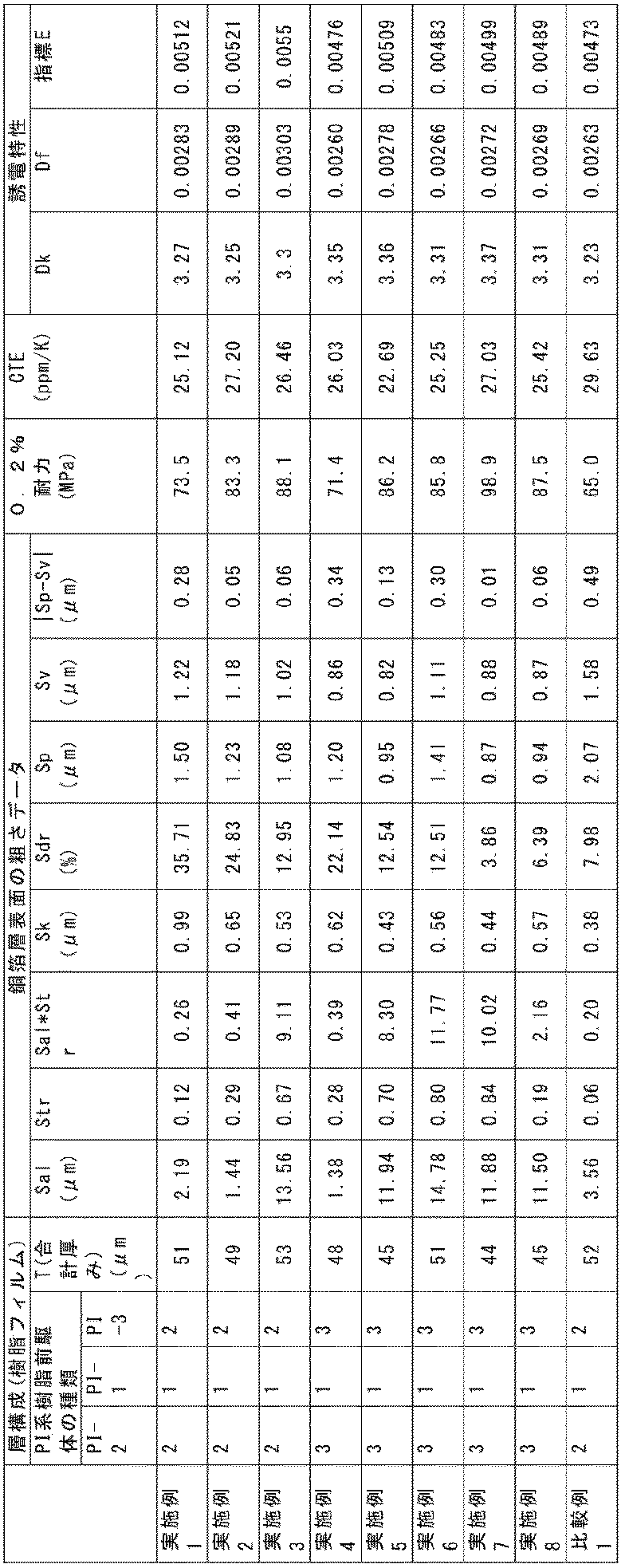
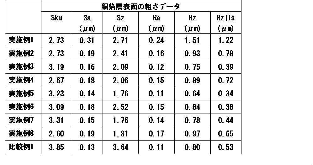
表1に示される通り、実施例で得られた積層体1~8は、比較例1で得られた積層体9と比べて、0.2%耐力が大きいことが確認された。よって、本発明の積層体は、高い耐力を有することが確認された。
<銅箔層-樹脂フィルム界面の粗度パラメータ測定>
(FIB加工前処理)
実施例及び比較例で得られた積層体1~9の一部をカットし、カットした試験片の端面をウルトラミクロトーム(Leica社製、 「Leica EM UC7」)で加工し平滑な厚み方向断面を有する試料を作成した。その後、積層体の樹脂側が接着面となるように、この試料をSEMのサンプルホルダーにカーボンテープで固定した。さらにイオンスパッタ装置を用いて、積層体の銅箔表面に、下記の条件で2回白金蒸着を行った(図1(a)参照)。
イオンスパッタ条件
装置:MC1000 ((株)日立ハイテク)
電流値:10mA
スパッタ時間:300秒
(FIB加工前処理)
実施例及び比較例で得られた積層体1~9の一部をカットし、カットした試験片の端面をウルトラミクロトーム(Leica社製、 「Leica EM UC7」)で加工し平滑な厚み方向断面を有する試料を作成した。その後、積層体の樹脂側が接着面となるように、この試料をSEMのサンプルホルダーにカーボンテープで固定した。さらにイオンスパッタ装置を用いて、積層体の銅箔表面に、下記の条件で2回白金蒸着を行った(図1(a)参照)。
イオンスパッタ条件
装置:MC1000 ((株)日立ハイテク)
電流値:10mA
スパッタ時間:300秒
(FIB加工処理)
積層体の銅箔表面に対して垂直方向からビームを照射し、ミクロトームで加工した端面中央の一部を、銅箔表面側から平面視したときにコの字型になるように切り取り、平滑な断面(観察面)を作成した。加工時の加速電圧、ビーム電流は適宜調整し、最後の加工工程では下記の条件で仕上げた(図1(b)参照)。加工した断面のうち、上述のミクロトーム加工面に平行な面を観察面とした(図1(c)参照)。
仕上げ条件
FIB-SEM装置:Helios G4 UX (ThermoFisher SCIENTIFIC)
加速電圧:20kV
ビーム電流:1.2nA
積層体の銅箔表面に対して垂直方向からビームを照射し、ミクロトームで加工した端面中央の一部を、銅箔表面側から平面視したときにコの字型になるように切り取り、平滑な断面(観察面)を作成した。加工時の加速電圧、ビーム電流は適宜調整し、最後の加工工程では下記の条件で仕上げた(図1(b)参照)。加工した断面のうち、上述のミクロトーム加工面に平行な面を観察面とした(図1(c)参照)。
仕上げ条件
FIB-SEM装置:Helios G4 UX (ThermoFisher SCIENTIFIC)
加速電圧:20kV
ビーム電流:1.2nA
(SEM観察前処理)
イオンスパッタ装置を用いて、下記の条件でFIB加工面(観察面)側に白金蒸着を行った。
イオンスパッタ条件
装置:MC1000 ((株)日立ハイテク)
電流値:10mA
スパッタ時間:20秒
イオンスパッタ装置を用いて、下記の条件でFIB加工面(観察面)側に白金蒸着を行った。
イオンスパッタ条件
装置:MC1000 ((株)日立ハイテク)
電流値:10mA
スパッタ時間:20秒
(SEM観察)
下記の条件で、積層体1~9の観察面のSEM観察を実施し、SEM像を得た。その際、銅箔層と樹脂フィルムの界面が画像に対して水平になるよう角度を調整した。
SEM観察条件
装置:Helios G4 UX (ThermoFisher SCIENTIFIC)
SEMモード:Mode2
検出器:Thru-the-Lens検出器
撮影条件:
観察倍率:10,000倍
観察像:BSE像
加速電圧:5kV
ビーム電流:0.1nA
Dwell time:5us
Line Integration:1
解像度:3072×2048 (0.147pixel/nm)
保存形式:Tiff
下記の条件で、積層体1~9の観察面のSEM観察を実施し、SEM像を得た。その際、銅箔層と樹脂フィルムの界面が画像に対して水平になるよう角度を調整した。
SEM観察条件
装置:Helios G4 UX (ThermoFisher SCIENTIFIC)
SEMモード:Mode2
検出器:Thru-the-Lens検出器
撮影条件:
観察倍率:10,000倍
観察像:BSE像
加速電圧:5kV
ビーム電流:0.1nA
Dwell time:5us
Line Integration:1
解像度:3072×2048 (0.147pixel/nm)
保存形式:Tiff
(断面曲線の作成)
Image J(NIH)を使用し、以下の工程により積層体1~9の銅箔層と樹脂フィルムとの界面の断面曲線(界面の輪郭形状曲線)を作成した(英語表記はImage J内でのツール名)。
1)画像の取り込み
Image Jにて、上記で得たSEM像を取り込んだ。この時、銅箔層の凸部が上向きになる方向で取り込みを行った。
2)スムージング
Smooth機能を用い、2回スムージング処理を行った。
3)コントラスト調整
低輝度側に存在する樹脂フィルム(樹脂層)由来のヒストグラムの高輝度側端部を最小値、高輝度側に存在する銅箔層由来のヒストグラムの低輝度側端部を最大値としてコントラスト調整を実施した。
4)二値化
Threshold機能を用い、Auto threshold methodとして、Default (modified IsoData Algorithm)を選択して実行した。
5)ノイズ除去
Remove Outliers機能を用い、下記条件での処理を順に実施した。
1回目
Radius=4pixel
Threshold=50
Witch Outlier=white
2回目
Radius=4pixel
Threshold=50
Witch Outlier=Black
その後、銅箔部分から孤立した白い粒状部分、樹脂部分から孤立した黒い粒状部分は、手動でfill toolを使用して除去した。
6)輪郭抽出
Find Edge、Skeletonizeの順で実行し、銅箔層と樹脂フィルムの界面である輪郭部を抽出することで、輪郭曲線を得た。その後、Save XY Coordinatesを使用して、輪郭曲線の座標をcsv形式で出力した(輪郭曲線は、銅箔層の凸部に対応するピークが上向きの曲線であり、すなわち銅箔層が下側、樹脂フィルム側が上側にある場合の界面の輪郭線である)。
7)断面曲線の補正
まず、Excelを用い、輪郭曲線の回帰直線の傾きaを算出し、各座標(x,y)においてy’=y-x×aを求め、(x,y’)として置き直し、輪郭曲線の傾き補正を行った。その後、全座標のy’値を使用して平均値bを算出し、各座標(x,y’)においてy’’=y’-bを求め、(x,y’’)と置き直し、輪郭曲線の平均値補正を行った。このとき、単位をpixelからnmに変換した(0.147pixel/nm)。これにより、傾き補正及び平均補正後の輪郭曲線、すなわち断面曲線を得た。
(界面の粗度パラメータの算出)
上記断面曲線を用いて、下記の式より、Pq、Pku、Pskを算出し、|Pku/Psk|を求めた。また、上記断面曲線から、最大山高さPp、最大谷深さPv、最大高さPz、及び算術平均高さPaも算出し、|Pp-Pv|を求めた。

[式中、Pkuはクルトシスを表し、Pskはスキューネスを表し、Pqは二乗平均平方根高さを表し、Lは最大x値-最小x値(すなわち、断面曲線の端から端までの距離;基準長さ)を表す]
上記断面曲線を用いて、下記の式より、Pq、Pku、Pskを算出し、|Pku/Psk|を求めた。また、上記断面曲線から、最大山高さPp、最大谷深さPv、最大高さPz、及び算術平均高さPaも算出し、|Pp-Pv|を求めた。
上記測定を行った結果を表3に示す。

1…白金蒸着
2…試料
3…サンプルホルダー
4…加工面(予めミクロトームで加工)
5…FIB照射
6…SEM観察向き(電子線照射方向)
7…補正前の輪郭曲線
8…傾き補正後の輪郭曲線
9…傾き補正及び平均値補正後の輪郭曲線(断面曲線)
10…樹脂フィルム
11…ポリイミド系樹脂含有層(層(PI-2)に相当)
12…ポリイミド系樹脂含有層(層(PI-1)に相当)
13…ポリイミド系樹脂含有層(層(PI-3)に相当)
14…金属層
15…積層体
2…試料
3…サンプルホルダー
4…加工面(予めミクロトームで加工)
5…FIB照射
6…SEM観察向き(電子線照射方向)
7…補正前の輪郭曲線
8…傾き補正後の輪郭曲線
9…傾き補正及び平均値補正後の輪郭曲線(断面曲線)
10…樹脂フィルム
11…ポリイミド系樹脂含有層(層(PI-2)に相当)
12…ポリイミド系樹脂含有層(層(PI-1)に相当)
13…ポリイミド系樹脂含有層(層(PI-3)に相当)
14…金属層
15…積層体
Claims (18)
- 樹脂フィルムと、該樹脂フィルムの少なくとも一方の面に設けられた金属層とを含む積層体であって、
前記金属層の前記樹脂フィルムと接する面は、ISO25178に準拠して、レーザー顕微鏡により、観察倍率100倍、Sフィルターによるカットオフ波長0.375μm及びLフィルター無しの条件で測定される最小自己相関長さSal及び表面性状のアスペクト比Strが、式(I):
Sal×Str≧0.21 (I)
の関係を満たす、積層体。 - 前記金属層の前記樹脂フィルムと接する面は、前記条件で測定されるコア部のレベル差Skが0.40μm以上である、請求項1に記載の積層体。
- 前記金属層の前記樹脂フィルムと接する面は、前記条件で測定される最大山高さSpと最大谷深さSvとの差の絶対値が0.48μm以下である、請求項1又は2に記載の積層体。
- 前記金属層の前記樹脂フィルムと接する面は、前記条件で測定される展開面積比Sdrが20%以下である、請求項1又は2に記載の積層体。
- 前記樹脂フィルムは、ポリイミド系樹脂、液晶ポリマー、フッ素系樹脂、芳香族ポリエーテル系樹脂、エポキシ系樹脂及びマレイミド系樹脂からなる群から選択される少なくとも1つの樹脂を含む、請求項1又は2に記載の積層体。
- 前記樹脂フィルムの熱膨張係数は10~29ppm/Kである、請求項1又は2に記載の積層体。
- 前記樹脂フィルムは、ポリイミド系樹脂を含有するポリイミド系フィルムである、請求項1又は2に記載の積層体。
- 前記ポリイミド系フィルムは、ポリイミド系樹脂含有層(PI-1)とポリイミド系樹脂含有層(PI-2)とを含む、請求項7に記載の積層体。
- 前記ポリイミド系樹脂含有層(PI-2)は前記金属層側に位置し、該ポリイミド系樹脂含有層(PI-2)の厚みは、前記ポリイミド系樹脂含有層(PI-1)の厚みの0.05~0.3倍である、請求項8に記載の積層体。
- 前記ポリイミド系フィルムは、さらにポリイミド系樹脂含有層(PI-3)を含む、請求項8に記載の積層体。
- 前記ポリイミド系樹脂含有層(PI-1)に含まれるポリイミド系樹脂、前記ポリイミド系樹脂含有層(PI-2)に含まれるポリイミド系樹脂、及びポリイミド系樹脂含有層(PI-3)に含まれるポリイミド系樹脂は、それぞれ40℃における貯蔵弾性率が1.0×10⁹Pa以上であるポリイミド系樹脂を含む、請求項10に記載の積層体。
- 前記ポリイミド系樹脂含有層(PI-1)及び前記ポリイミド系樹脂含有層(PI-2)の少なくとも1層は、テトラカルボン酸無水物由来の構成単位(A)を有するポリイミド系樹脂を含み、
前記構成単位(A)は、式(A1):

kは、0~2の整数を表す]
で表されるテトラカルボン酸無水物由来の構成単位(A1)、及び/又は、式(A2):
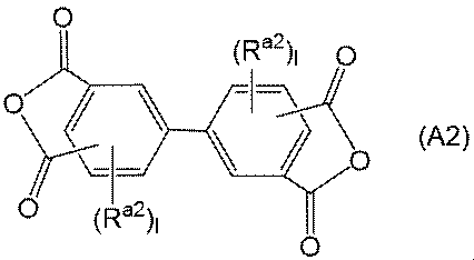
で表されるテトラカルボン酸無水物由来の構成単位(A2)を含む、請求項8に記載の積層体。 - 前記ポリイミド系樹脂含有層(PI-1)及び前記ポリイミド系樹脂含有層(PI-2)の少なくとも1層は、ジアミン由来の構成単位(B)を有するポリイミド系樹脂を含み、
前記構成単位(B)は、式(B1):
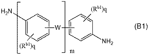
Wは、互いに独立に、-O-、-CH2-、-CH2-CH2-、-CH(CH3)-、-C(CH3)2-、-C(CF3)2-、-COO-、-OOC-、-SO-、-SO2-、-S-、-CO-、-N(Rc)-及び-CONH-からなる群から選択される2価の連結基、又は、単結合(但し、mは2以上であり、少なくとも1つのWは前記2価の連結基である)を表し、Rcは水素原子、又はハロゲン原子で置換されていてもよい炭素数1~12の一価の炭化水素基を表し、
mは1~4の整数を表し、
qは互いに独立に、0~4の整数を表す]
で表されるジアミン由来の構成単位(B1)を含む、請求項8に記載の積層体。 - 少なくとも前記ポリイミド系樹脂含有層(PI-1)は、テトラカルボン酸無水物由来の構成単位(A)を有するポリイミド系樹脂を含み、該構成単位(A)は、式(A3):
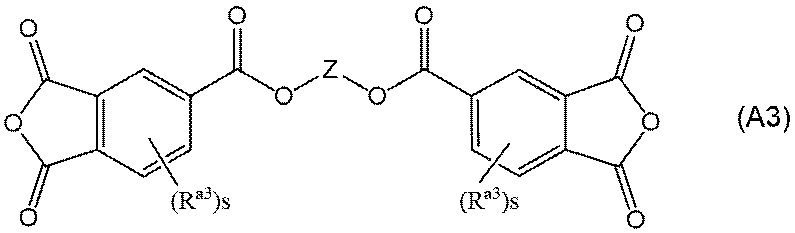
Ra3は、互いに独立に、ハロゲン原子、又はハロゲン原子を有してもよいアルキル基、アルコキシ基、アリール基若しくはアリールオキシ基を表し、
sは互いに独立に、0~3の整数を表す]
で表されるエステル結合含有テトラカルボン酸無水物由来の構成単位(A3)を含む、請求項8に記載の積層体。 - 少なくとも前記ポリイミド系樹脂含有層(PI-1)に含まれるポリイミド系樹脂が前記構成単位(A)を有し、該構成単位(A)はさらに、該構成単位(A)の総量に対して50モル%以下の式(A3):
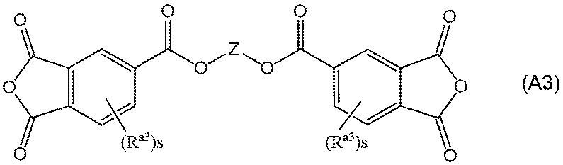
Ra3は、互いに独立に、ハロゲン原子、又はハロゲン原子を有してもよいアルキル基、アルコキシ基、アリール基若しくはアリールオキシ基を表し、
sは互いに独立に、0~3の整数を表す]
で表されるエステル結合含有テトラカルボン酸無水物由来の構成単位(A3)を含む、請求項12に記載の積層体。 - 前記樹脂フィルムの両面に金属層を有する、請求項1又は2に記載の積層体。
- 前記金属層は銅層である、請求項1又は2に記載の積層体。
- 請求項1又は2に記載の積層体を含む、フレキシブルプリント回路基板。
Priority Applications (2)
| Application Number | Priority Date | Filing Date | Title |
|---|---|---|---|
| KR1020267016368A KR20260114551A (ko) | 2023-11-10 | 2024-10-24 | 적층체 |
| CN202480070254.2A CN122122010A (zh) | 2023-11-10 | 2024-10-24 | 层叠体 |
Applications Claiming Priority (2)
| Application Number | Priority Date | Filing Date | Title |
|---|---|---|---|
| JP2023192597 | 2023-11-10 | ||
| JP2023-192597 | 2023-11-10 |
Publications (1)
| Publication Number | Publication Date |
|---|---|
| WO2025100252A1 true WO2025100252A1 (ja) | 2025-05-15 |
Family
ID=95695906
Family Applications (1)
| Application Number | Title | Priority Date | Filing Date |
|---|---|---|---|
| PCT/JP2024/037980 Pending WO2025100252A1 (ja) | 2023-11-10 | 2024-10-24 | 積層体 |
Country Status (5)
| Country | Link |
|---|---|
| JP (1) | JP2025079796A (ja) |
| KR (1) | KR20260114551A (ja) |
| CN (1) | CN122122010A (ja) |
| TW (1) | TW202530017A (ja) |
| WO (1) | WO2025100252A1 (ja) |
Cited By (1)
| Publication number | Priority date | Publication date | Assignee | Title |
|---|---|---|---|---|
| WO2026034345A1 (ja) * | 2024-08-05 | 2026-02-12 | 住友化学株式会社 | 積層体 |
Citations (10)
| Publication number | Priority date | Publication date | Assignee | Title |
|---|---|---|---|---|
| JP2010120239A (ja) * | 2008-11-19 | 2010-06-03 | Nippon Steel Chem Co Ltd | 金属張積層体およびその製造方法 |
| JP2013028146A (ja) * | 2011-07-29 | 2013-02-07 | Kaneka Corp | 金属張積層板の製造方法 |
| JP2021095596A (ja) * | 2019-12-13 | 2021-06-24 | Jx金属株式会社 | 表面処理銅箔、銅張積層板及びプリント配線板 |
| WO2021157363A1 (ja) * | 2020-02-04 | 2021-08-12 | 三井金属鉱業株式会社 | 粗化処理銅箔、キャリア付銅箔、銅張積層板及びプリント配線板 |
| WO2022255420A1 (ja) * | 2021-06-03 | 2022-12-08 | 三井金属鉱業株式会社 | 粗化処理銅箔、銅張積層板及びプリント配線板 |
| WO2022257800A1 (zh) * | 2021-06-08 | 2022-12-15 | 广州方邦电子股份有限公司 | 金属箔、带载体金属箔、覆铜层叠板及印刷线路板 |
| US20230082055A1 (en) * | 2021-09-03 | 2023-03-16 | Contemporary Amperex Technology Co., Limited | Metal foil and preparation method thereof, current collector, electrode, battery, and electrical device |
| WO2023127681A1 (ja) * | 2021-12-28 | 2023-07-06 | 四国化成工業株式会社 | 有機被膜およびその製造方法 |
| JP7336614B1 (ja) * | 2023-03-29 | 2023-08-31 | 住友化学株式会社 | 積層フィルム |
| JP7357815B1 (ja) * | 2023-03-29 | 2023-10-06 | 住友化学株式会社 | 積層フィルム |
-
2024
- 2024-10-21 JP JP2024185028A patent/JP2025079796A/ja active Pending
- 2024-10-24 CN CN202480070254.2A patent/CN122122010A/zh active Pending
- 2024-10-24 WO PCT/JP2024/037980 patent/WO2025100252A1/ja active Pending
- 2024-10-24 KR KR1020267016368A patent/KR20260114551A/ko active Pending
- 2024-11-05 TW TW113142269A patent/TW202530017A/zh unknown
Patent Citations (10)
| Publication number | Priority date | Publication date | Assignee | Title |
|---|---|---|---|---|
| JP2010120239A (ja) * | 2008-11-19 | 2010-06-03 | Nippon Steel Chem Co Ltd | 金属張積層体およびその製造方法 |
| JP2013028146A (ja) * | 2011-07-29 | 2013-02-07 | Kaneka Corp | 金属張積層板の製造方法 |
| JP2021095596A (ja) * | 2019-12-13 | 2021-06-24 | Jx金属株式会社 | 表面処理銅箔、銅張積層板及びプリント配線板 |
| WO2021157363A1 (ja) * | 2020-02-04 | 2021-08-12 | 三井金属鉱業株式会社 | 粗化処理銅箔、キャリア付銅箔、銅張積層板及びプリント配線板 |
| WO2022255420A1 (ja) * | 2021-06-03 | 2022-12-08 | 三井金属鉱業株式会社 | 粗化処理銅箔、銅張積層板及びプリント配線板 |
| WO2022257800A1 (zh) * | 2021-06-08 | 2022-12-15 | 广州方邦电子股份有限公司 | 金属箔、带载体金属箔、覆铜层叠板及印刷线路板 |
| US20230082055A1 (en) * | 2021-09-03 | 2023-03-16 | Contemporary Amperex Technology Co., Limited | Metal foil and preparation method thereof, current collector, electrode, battery, and electrical device |
| WO2023127681A1 (ja) * | 2021-12-28 | 2023-07-06 | 四国化成工業株式会社 | 有機被膜およびその製造方法 |
| JP7336614B1 (ja) * | 2023-03-29 | 2023-08-31 | 住友化学株式会社 | 積層フィルム |
| JP7357815B1 (ja) * | 2023-03-29 | 2023-10-06 | 住友化学株式会社 | 積層フィルム |
Cited By (1)
| Publication number | Priority date | Publication date | Assignee | Title |
|---|---|---|---|---|
| WO2026034345A1 (ja) * | 2024-08-05 | 2026-02-12 | 住友化学株式会社 | 積層体 |
Also Published As
| Publication number | Publication date |
|---|---|
| JP2025079796A (ja) | 2025-05-22 |
| KR20260114551A (ko) | 2026-07-22 |
| TW202530017A (zh) | 2025-08-01 |
| CN122122010A (zh) | 2026-05-29 |
Similar Documents
| Publication | Publication Date | Title |
|---|---|---|
| JP7357815B1 (ja) | 積層フィルム | |
| JP7336614B1 (ja) | 積層フィルム | |
| JP2025079796A (ja) | 積層体 | |
| KR20230078550A (ko) | 폴리이미드계 수지 전구체 | |
| CN118721908A (zh) | 层叠膜 | |
| WO2025100253A1 (ja) | 積層体 | |
| JP2025079794A (ja) | 積層体 | |
| JP2025079795A (ja) | 積層体 | |
| WO2025100254A1 (ja) | 積層体 | |
| JP7519509B1 (ja) | ポリイミド系フィルム | |
| WO2026034345A1 (ja) | 積層体 | |
| JP2026027185A (ja) | 積層体 | |
| JP2024142264A (ja) | 積層フィルム | |
| JP2024122828A (ja) | ポリイミド系フィルム | |
| JP2024142260A (ja) | 積層フィルム | |
| JP2024122829A (ja) | ポリイミド系フィルム | |
| TW202449035A (zh) | 聚醯亞胺系薄膜 | |
| JP2024101973A (ja) | ポリイミド系樹脂 | |
| JP2024101974A (ja) | ポリイミド系樹脂 | |
| TW202448694A (zh) | 聚醯亞胺系薄膜 | |
| CN118560113A (zh) | 聚酰亚胺系膜 | |
| CN118359809A (zh) | 聚酰亚胺系树脂 | |
| CN118560115A (zh) | 聚酰亚胺系膜 |
Legal Events
| Date | Code | Title | Description |
|---|---|---|---|
| 121 | Ep: the epo has been informed by wipo that ep was designated in this application |
Ref document number: 24888549 Country of ref document: EP Kind code of ref document: A1 |
|
| NENP | Non-entry into the national phase |
Ref country code: DE |