WO2025100124A1 - 成形型、樹脂成形装置、及び樹脂成形品の製造方法 - Google Patents
成形型、樹脂成形装置、及び樹脂成形品の製造方法 Download PDFInfo
- Publication number
- WO2025100124A1 WO2025100124A1 PCT/JP2024/034628 JP2024034628W WO2025100124A1 WO 2025100124 A1 WO2025100124 A1 WO 2025100124A1 JP 2024034628 W JP2024034628 W JP 2024034628W WO 2025100124 A1 WO2025100124 A1 WO 2025100124A1
- Authority
- WO
- WIPO (PCT)
- Prior art keywords
- resin
- mold
- molding
- cavity
- movable member
- Prior art date
- Legal status (The legal status is an assumption and is not a legal conclusion. Google has not performed a legal analysis and makes no representation as to the accuracy of the status listed.)
- Pending
Links
Images



Classifications
-
- B—PERFORMING OPERATIONS; TRANSPORTING
- B29—WORKING OF PLASTICS; WORKING OF SUBSTANCES IN A PLASTIC STATE IN GENERAL
- B29C—SHAPING OR JOINING OF PLASTICS; SHAPING OF MATERIAL IN A PLASTIC STATE, NOT OTHERWISE PROVIDED FOR; AFTER-TREATMENT OF THE SHAPED PRODUCTS, e.g. REPAIRING
- B29C33/00—Moulds or cores; Details thereof or accessories therefor
- B29C33/42—Moulds or cores; Details thereof or accessories therefor characterised by the shape of the moulding surface, e.g. ribs or grooves
-
- B—PERFORMING OPERATIONS; TRANSPORTING
- B29—WORKING OF PLASTICS; WORKING OF SUBSTANCES IN A PLASTIC STATE IN GENERAL
- B29C—SHAPING OR JOINING OF PLASTICS; SHAPING OF MATERIAL IN A PLASTIC STATE, NOT OTHERWISE PROVIDED FOR; AFTER-TREATMENT OF THE SHAPED PRODUCTS, e.g. REPAIRING
- B29C33/00—Moulds or cores; Details thereof or accessories therefor
- B29C33/44—Moulds or cores; Details thereof or accessories therefor with means for, or specially constructed to facilitate, the removal of articles, e.g. of undercut articles
-
- B—PERFORMING OPERATIONS; TRANSPORTING
- B29—WORKING OF PLASTICS; WORKING OF SUBSTANCES IN A PLASTIC STATE IN GENERAL
- B29C—SHAPING OR JOINING OF PLASTICS; SHAPING OF MATERIAL IN A PLASTIC STATE, NOT OTHERWISE PROVIDED FOR; AFTER-TREATMENT OF THE SHAPED PRODUCTS, e.g. REPAIRING
- B29C45/00—Injection moulding, i.e. forcing the required volume of moulding material through a nozzle into a closed mould; Apparatus therefor
- B29C45/02—Transfer moulding, i.e. transferring the required volume of moulding material by a plunger from a "shot" cavity into a mould cavity
-
- B—PERFORMING OPERATIONS; TRANSPORTING
- B29—WORKING OF PLASTICS; WORKING OF SUBSTANCES IN A PLASTIC STATE IN GENERAL
- B29C—SHAPING OR JOINING OF PLASTICS; SHAPING OF MATERIAL IN A PLASTIC STATE, NOT OTHERWISE PROVIDED FOR; AFTER-TREATMENT OF THE SHAPED PRODUCTS, e.g. REPAIRING
- B29C45/00—Injection moulding, i.e. forcing the required volume of moulding material through a nozzle into a closed mould; Apparatus therefor
- B29C45/17—Component parts, details or accessories; Auxiliary operations
- B29C45/26—Moulds
- B29C45/37—Mould cavity walls, i.e. the inner surface forming the mould cavity, e.g. linings
-
- B—PERFORMING OPERATIONS; TRANSPORTING
- B29—WORKING OF PLASTICS; WORKING OF SUBSTANCES IN A PLASTIC STATE IN GENERAL
- B29C—SHAPING OR JOINING OF PLASTICS; SHAPING OF MATERIAL IN A PLASTIC STATE, NOT OTHERWISE PROVIDED FOR; AFTER-TREATMENT OF THE SHAPED PRODUCTS, e.g. REPAIRING
- B29C45/00—Injection moulding, i.e. forcing the required volume of moulding material through a nozzle into a closed mould; Apparatus therefor
- B29C45/17—Component parts, details or accessories; Auxiliary operations
- B29C45/40—Removing or ejecting moulded articles
-
- B—PERFORMING OPERATIONS; TRANSPORTING
- B29—WORKING OF PLASTICS; WORKING OF SUBSTANCES IN A PLASTIC STATE IN GENERAL
- B29C—SHAPING OR JOINING OF PLASTICS; SHAPING OF MATERIAL IN A PLASTIC STATE, NOT OTHERWISE PROVIDED FOR; AFTER-TREATMENT OF THE SHAPED PRODUCTS, e.g. REPAIRING
- B29C45/00—Injection moulding, i.e. forcing the required volume of moulding material through a nozzle into a closed mould; Apparatus therefor
- B29C45/17—Component parts, details or accessories; Auxiliary operations
- B29C45/46—Means for plasticising or homogenising the moulding material or forcing it into the mould
- B29C45/56—Means for plasticising or homogenising the moulding material or forcing it into the mould using mould parts movable during or after injection, e.g. injection-compression moulding
-
- H—ELECTRICITY
- H10—SEMICONDUCTOR DEVICES; ELECTRIC SOLID-STATE DEVICES NOT OTHERWISE PROVIDED FOR
- H10W—GENERIC PACKAGES, INTERCONNECTIONS, CONNECTORS OR OTHER CONSTRUCTIONAL DETAILS OF DEVICES COVERED BY CLASS H10
- H10W74/00—Encapsulations, e.g. protective coatings
- H10W74/01—Manufacture or treatment
Definitions
- This disclosure relates to a molding die, a resin molding device, and a method for manufacturing a resin molded product.
- Substrates with semiconductor chips fixed thereto are generally used as electronic components by being resin-sealed.
- resin molding devices equipped with molding dies for resin-sealing substrates and the like have been known (see, for example, Patent Document 1).
- Patent Document 1 discloses a transfer molding device (called a molding device in Patent Document 1) that is configured to fill a cavity (the product part in Patent Document 1) and a resin reservoir with molten resin using an extrusion plunger, and then to increase the volume of the resin reservoir by lowering an increase plunger.
- This transfer molding device is configured so that when the increase plunger is lowered to cause the resin to flow from the cavity to the resin reservoir, air bubbles in the cavity are moved to the resin reservoir together with the resin.
- One embodiment of the molding die according to the present disclosure comprises a first die in which an object to be molded is placed, and a second die that is placed opposite the first die and holds a release film on the opposing surface facing the first die, and at least one of the first die and the second die is formed with a cavity that contains the object to be molded and is supplied with molten resin material from a pot, and a surplus resin storage cavity that stores the surplus resin material that flows out of the cavity after being supplied to the cavity, and the second die has a movable member that can move forward from the inner surface of the surplus resin storage cavity toward the surplus resin storage cavity and backward from the surplus resin storage cavity, and a protrusion that is formed on at least a portion of the inner surface of the cavity around the movable member and protrudes from the inner surface of the cavity toward the surplus resin storage cavity.
- One embodiment of the resin molding device includes the molding die described above, a clamping mechanism for clamping and opening the molding die, an ejection mechanism for ejecting the resin molded product, which is the object to be molded after resin molding and which is separated from each other by opening the molding die after resin molding, and unnecessary resin parts of the resin material to the outside of the molding die, and a control unit for controlling the operation of the device.
- One embodiment of the method for manufacturing a resin molded product according to the present disclosure is a method for manufacturing a resin molded product using the resin molding apparatus described above, and includes a supplying step of supplying the molding object and the resin material to the molding die, a mold clamping step of clamping the molding die using the mold clamping mechanism, and a molding step of resin molding the molding object by supplying the molten resin material from the pot to the cavity, and causing the movable member to move backward toward the inner surface of the cavity due to the pressure of the surplus resin material stored in the surplus resin storage cavity.
- a molding die, a resin molding device, and a method for manufacturing a resin molded product that are less likely to cause wrinkles in the release film during resin molding and prevent the release film from becoming caught in the hardened resin.
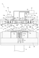
- FIG. 2 is a schematic plan view showing a resin molding apparatus.
- FIG. 4 is a cross-sectional view showing a molding process. 4 is a cross-sectional view showing a molding process. 4 is a cross-sectional view showing a molding process. 4 is a cross-sectional view showing a molding process.
- FIG. 4 is a flow diagram showing a mold opening operation in a molding process.
- Substrates with semiconductor chips etc. fixed on them can be resin-sealed to be used as electronic components.
- Techniques for resin-sealing molding objects include the transfer method.
- One transfer method involves placing the molding object on the lower die of a molding die, placing a release film on the upper die of the molding die, feeding a resin tablet of solidified powdered resin into the mold pot, heating and melting it, and feeding the molten resin into the cavity to resin-mold the molding object.
- the resin tablet is made of a solid resin made by compressing powdered resin into a solid form, which melts when heated to become a liquid molten resin.
- the resin tablet may be a thermoplastic resin or a thermosetting resin.
- Thermosetting resin reduces in viscosity when heated, and when heated further, it polymerizes and hardens to become a hardened resin.
- a pre-molded substrate with a semiconductor chip fixed thereto is to be resin molded and sealed, it is desirable to use a thermosetting resin.
- FIG. 1 shows a schematic plan view of the resin molding apparatus 30 in this embodiment.
- the resin molding apparatus 30 includes a storage module 2, a molding module 3, a supply module 4, a control unit 6, a loader 41, and an unloader 42 (an example of a carrying-out mechanism).
- the molding module 3 is a part that resin-seals the molding object, and has a molding die C that holds a pre-molded substrate Sa (an example of a molding object).
- the molding die C has an upper die UM (an example of a second die) and a lower die LM (an example of a first die).
- the resin molding apparatus 30 in this embodiment is an apparatus that resin-moldes a pre-molded substrate Sa to which a semiconductor chip 48 (see FIG. 2) or the like is fixed.
- the supply module 4 is for supplying pre-molded substrates Sa and resin tablets T (an example of a resin material) to the molding module 3, and includes a substrate supply mechanism 43 and a resin supply mechanism 45.
- the substrate supply mechanism 43 stocks pre-molded substrates Sa, and arranges the pre-molded substrates Sa in a state suitable for transport.
- a plurality of semiconductor chips 48 are aligned vertically and/or horizontally and fixed to the pre-molded substrate Sa.
- the resin supply mechanism 45 stocks resin tablets T, and arranges the resin tablets T in a state suitable for transport.
- the pre-molded substrate Sa may be one to which one semiconductor chip 48 is fixed.
- the loader 41 waits in the supply module 4.
- the loader 41 receives the pre-molded substrate Sa from the substrate supply mechanism 43, and also receives the resin tablet T from the resin supply mechanism 45, and moves from the supply module 4 to the molding module 3 on rails (not shown) arranged on the rear side (upper side in FIG. 1) from the supply module 4 to the molding module 3.
- the loader 41 then transfers the pre-molded substrate Sa and the resin tablet T to the lower mold LM of the molding module 3.
- the loader 41 then moves again on the rails to the supply module 4.
- the molding module 3 uses a molding die C to resin-seal the pre-molded substrate Sa to form a molded substrate Sb (an example of a resin molded product).
- a molding die C to resin-seal the pre-molded substrate Sa to form a molded substrate Sb (an example of a resin molded product).
- one molding module 3 is provided, but two or more may be provided. When two or more molding modules are provided, each molding module 3 can be attached or detached independently.
- the storage module 2 has a substrate storage section 46.
- the unloader 42 waits in the storage module 2 and moves along rails (not shown) arranged on the rear side (upper side in FIG. 1) from the storage module 2 to the molding module 3 to remove the molded substrate Sb from the molding module 3, and then moves along the rails again to the storage module 2 to store the molded substrate Sb in the substrate storage section 46.
- the semiconductor chip 48 and the like are sealed with a cured resin formed by solidifying molten resin Ta (an example of a resin material, see FIG. 2).
- the control unit 6 includes a processor such as a CPU (Central Processing Unit) and a storage device such as a RAM (Random Access Memory).
- the control unit 6 controls the operation of the resin molding device 30 by executing a control program stored in the storage device with the processor.
- the operation of the resin molding device 30 described below is performed based on operation commands from the control unit 6 unless otherwise specified. In the following description, the operation commands from the control unit 6 will be omitted as a general rule, and will be described as necessary.
- the mold C has an upper mold UM in which an upper mold cavity MC (one example of a cavity) is formed, into which the resin tablet T is heated and melted to supply the molten resin Ta, a lower mold LM arranged opposite the upper mold UM and provided with a pot block 71 forming a resin flow path that supplies the molten resin Ta to the upper mold cavity MC, and a clamping mechanism 5 that clamps the upper mold UM and the lower mold LM.
- an upper mold UM in which an upper mold cavity MC (one example of a cavity) is formed, into which the resin tablet T is heated and melted to supply the molten resin Ta
- a lower mold LM arranged opposite the upper mold UM and provided with a pot block 71 forming a resin flow path that supplies the molten resin Ta to the upper mold cavity MC
- a clamping mechanism 5 that clamps the upper mold UM and the lower mold LM.
- one pre-molded substrate Sa is placed on each side of the pot block 71 of the lower mold LM, and two pre-molded substrates Sa are resin-molded by one resin molding operation, but this is not particularly limited to this configuration, and one pre-molded substrate Sa may be resin-molded by one resin molding operation.
- the operation of the clamping mechanism 5 is controlled by the control unit 6.
- the pre-molded substrate Sa is transported between the upper mold UM and the lower mold LM by the loader 41, and then placed on the lower mold LM.
- the shape of the pre-molded substrate Sa is rectangular, and accordingly, the planar shape of the upper mold cavity MC is also rectangular.
- the lower mold LM is held by a lower mold holder 32, which is fixed to a movable platen 34 that is raised and lowered by a mold clamping mechanism 5.
- the mold clamping mechanism 5 in this embodiment can be, for example, a combination of a servo motor and a ball screw mechanism, or a combination of an air cylinder or hydraulic cylinder and a rod.
- the upper mold UM includes an upper mold base plate 31.
- a release film F is disposed on a surface 33 (an example of an opposing surface) of the upper mold UM, which is the mold surface facing the lower mold LM.
- the release film F is supplied by a release film supply mechanism (not shown).
- the release film F is adsorbed to the surface 33 of the upper mold UM by sucking air with a vacuum pump 37 from a second flow path 31b (an example of a suction hole) and a third flow path 31c (an example of a suction hole) which are suction holes formed in the upper mold UM.
- the release film F is adsorbed to the surface 33 of the upper mold UM by sucking air with a vacuum pump 37 from a fourth flow path (not shown) which is a suction hole formed on the outer periphery of the upper mold UM.
- a vacuum pump 37 a fourth flow path (not shown) which is a suction hole formed on the outer periphery of the upper mold UM.
- the path for sucking air from the second flow path 31b and the third flow path 31c by the vacuum pump 37 is separate from the path for sucking air from the fourth flow path by the vacuum pump 37.
- the material used for the release film F is a resin material that has properties such as heat resistance, releasability, flexibility, and extensibility, and examples of such materials include PTFE (polytetrafluoroethylene), ETFE (ethylene/tetrafluoroethylene copolymer), PET (polyethylene terephthalate), FEP (tetrafluoroethylene/hexafluoropropylene copolymer), polypropylene, polystyrene, and polyvinylidene chloride.
- PTFE polytetrafluoroethylene
- ETFE ethylene/tetrafluoroethylene copolymer
- PET polyethylene terephthalate
- FEP tetrafluoroethylene/hexafluoropropylene copolymer
- polypropylene polystyrene
- polystyrene polystyrene
- polyvinylidene chloride polyvinylidene chloride
- the molten resin supply mechanism 7 includes a pot block 71 in which a pot 71a for accommodating a resin tablet T is formed, and a transfer mechanism 72 having a plunger 72a provided within the pot 71a.
- the pot 71a is formed, for example, from a cylindrical member 73.
- the cylindrical member 73 is fitted into a through hole formed in the pot block 71.
- a first protruding portion 71e is formed that protrudes above the surface that is the mold surface of the lower mold LM. This first protruding portion 71e protrudes so that it can press the pot side end of the pre-molded substrate Sa when the pre-molded substrate Sa is placed on the lower mold LM. Furthermore, on the upper surface of the pot block 71, a cull portion 71b, a runner 71c, and a first lower gate 71d are formed, which serve as a resin flow path that introduces the molten resin Ta supplied from the pot 71a into the upper mold cavity MC.
- the first lower gate 71d that constitutes the resin supply gate is located inside (closer to the semiconductor chip 48) than the outer edge of the pre-molded substrate Sa on the side closer to the pot block 71.
- this method of clamping the pre-molded substrate Sa placed on the lower mold LM between the lower mold LM and the first protruding portion 71e of the pot block 71 to perform resin molding in which the molten resin Ta supplied from the pot 71a passes inside the outer edge of the pre-molded substrate Sa and is supplied to the upper mold cavity MC of the upper mold UM, is sometimes referred to as the edge gate method.
- the transfer mechanism 72 moves the plunger 72a while the upper mold UM and the lower mold LM are clamped, supplying the molten resin Ta from the pot 71a to the upper mold cavity MC.
- This transfer mechanism 72 includes a plunger 72a for pumping the molten resin Ta, a fixed block 72b to which the plunger 72a is fixed, and a plunger drive mechanism 72c for moving the plunger 72a via the fixed block 72b. The operation of the plunger drive mechanism 72c is controlled by the control unit 6.
- the fixed block 72b has a roughly rectangular parallelepiped shape, and multiple plungers 72a are fixed in a straight line to one surface (top surface) of the rectangular block 72b.
- the arrangement of the multiple plungers 72a corresponds to the arrangement of the multiple pots 71a described below.
- the multiple plungers 72a are fixed to the fixed block 72b, for example, by fixing screws.
- the fixed block 72b may also be provided with a pressure equalizing mechanism using an elastic member or the like to equalize the pressure with which each plunger 72a injects the molten resin Ta.
- the plunger drive mechanism 72c moves the fixed block 72b up and down relative to the lower mold LM, thereby moving the multiple plungers 72a up and down collectively by the same amount relative to the multiple pots 71a.
- the plunger drive mechanism 72c is provided below the fixed block 72b.
- the plunger drive mechanism 72c may be a combination of a servo motor and a ball screw mechanism, or a combination of an air cylinder or hydraulic cylinder and a rod.
- the upper mold UM is formed with an upper mold cavity MC that houses the semiconductor chip 48 of the pre-molded substrate Sa and into which the molten resin Ta is supplied.
- the upper mold UM is also formed with a concave space 35 and a first upper gate 35a that connect the cull portion 71b, runner 71c, and first lower gate 71d of the pot block 71 to the upper mold cavity MC.
- a resin flow path consisting of the cull portion 71b, the runner 71c, the first lower gate 71d, the recessed space 35, and the first upper gate 35a connects the multiple pots 71a to the upper mold cavity MC.
- the first lower gate 71d and the first upper gate 35a form a resin supply gate, through which the molten resin Ta of the pot 71a is supplied to the upper mold cavity MC.
- the resin supply gate (the gap between the first lower gate 71d and the first upper gate 35a) is located inside the outer edge of the pre-molded substrate Sa on the side closer to the pot block 71.
- the plunger 72a is raised by the plunger drive mechanism 72c to supply the molten resin Ta to the upper mold cavity MC
- the semiconductor chip 48 of the pre-molded substrate Sa is sealed with resin. It is also possible to omit the runner 71c and directly connect the cull portion 71b and the upper die cavity MC via the first lower gate 71d and the first upper gate 35a.
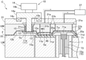
- the surplus resin storage mechanism 10 is composed of a surplus resin storage block 11, a second surplus resin storage cavity 12 (one example of a surplus resin storage cavity), a movable mechanism 14, and a protrusion 15a.
- the surplus resin storage block 11 is disposed in the lower mold LM on the opposite side of the pot block 71 from the location where the pre-molded substrate Sa is placed.
- the second surplus resin storage cavity 12 is formed in the upper mold UM on the opposite side of the recessed space 35 from the upper mold cavity MC.
- the lower mold LM has an air vent (not shown) formed on the opposite side of the pot block 71 from the surplus resin storage block 11.
- the second upper gate 12a is formed in the second surplus resin storage cavity 12 closest to the concave space 35.
- the surplus resin storage block 11 enters the second surplus resin storage cavity 12.
- the first surplus resin storage cavity 11a and the second surplus resin storage cavity 12 form the surplus resin storage space 13 (see FIG. 3).
- the second lower gate 11b and the second upper gate 12a form a resin discharge gate.
- the resin discharge gate is located inside the outer edge of the pre-molded substrate Sa (closer to the semiconductor chip 48) and is an edge gate type gate. At this time, when the upper mold UM and the lower mold LM are clamped, the lower surface of the second protruding portion 11c sandwiches the pre-molded substrate Sa between the surface of the lower mold LM.
- the upper mold UM and lower mold LM are clamped together, and the molten resin Ta in the pot 71a is supplied to the upper mold cavity MC.
- excess resin Tb an example of a resin material
- Excess resin Tb refers to the molten resin Ta that is discharged from the upper mold cavity MC into the excess resin storage space 13.
- the movable mechanism 14 is composed of a movable member 14a, a drive unit 14b, and a compression spring 14c.
- the movable member 14a is composed of a cylindrical portion and a flange portion extending radially outward from one end of the cylindrical portion.
- the cylindrical portion of the movable member 14a penetrates the upper mold UM and the upper mold base plate 31.
- the movable member 14a can perform forward and backward movement to protrude into the second surplus resin storage cavity 12 and retreat movement to retreat from the second surplus resin storage cavity 12.
- the movable member 14a is configured to be able to perform forward movement, which is movement toward the lower mold LM, and retreat movement, which is movement away from the lower mold LM, with respect to an inner surface 12b (an example of an inner cavity surface) of the surface 33 of the upper mold UM that is located within the second surplus resin storage cavity 12. That is, the inner surface 12b is the surface portion within the second excess resin storage cavity 12 of the upper mold UM.
- the flange portion of the movable member 14a is located on the upper side (outside) of the upper mold base plate 31.
- the drive unit 14b is a power source that makes the movable member 14a movable, and is, for example, a servo motor or an air cylinder.
- the compression spring 14c is connected to the upper mold base plate 31 and the flange portion of the movable member 14a, and applies the elastic force of the spring to the movable member 14a in a direction away from the lower mold LM (a direction in which the movable member 14a moves backward) when the movable member 14a moves forward.
- the protruding portion 15a is a portion that protrudes from the inner surface 12b of the second excess resin storage cavity 12 toward the lower mold LM.
- the protruding portion 15a corresponds to the end of the protruding member 15 having a cylindrical shape on the lower mold LM side.
- the protruding member 15 has a fixing portion 15b that extends slightly radially outward at the end opposite the protruding portion 15a.
- the protruding member 15 is fixed by pressing the fixing portion 15b into the upper mold UM. At this time, the end of the protruding member 15 that faces the lower mold LM protrudes from the inner surface 12b toward the lower mold LM as the protruding portion 15a.
- the movable member 14a is disposed in the space inside the protruding member 15, and the movable member 14a slides and moves on the inner peripheral surface of the protruding member 15. In other words, the protruding member 15 is in contact with the side (outer peripheral surface) of the movable member 14a.
- the surface of the upper mold base plate 31 that is in contact with the upper mold UM is formed with a groove-like first flow path 31a through which air flows.
- the first flow path 31a is connected to the second flow path 31b and the third flow path 31c formed in the upper mold UM.
- the second flow path 31b is a through hole that penetrates the upper mold UM from the first flow path 31a toward the lower mold LM.
- the end of the second flow path 31b opposite to the end connected to the first flow path 31a is located at least in the recessed space 35 and the upper mold cavity MC.
- the third flow path 31c is the gap between the inner circumferential surface of the protruding member 15 and the outer circumferential surface of the movable member 14a, and the gap between the outer circumferential surface of the protruding member 15 and the inner circumferential surface of the upper mold UM.
- the end of the protruding member 15 on the side of the fixed part 15b is connected to the first flow path 31a.
- the first flow path 31a is connected to a vacuum pump 37.
- the vacuum pump 37 has the function of sucking and supplying air. By sucking air in the first flow path 31a, the second flow path 31b, and the third flow path 31c with the vacuum pump 37, the release film F can be adsorbed onto the surface 33 of the upper mold UM.
- the manufacturing method of the resin molded product (molded substrate Sb) includes a supplying step of supplying a release film F to the upper mold UM and supplying a pre-molded substrate Sa and a resin tablet T to the lower mold LM, a mold clamping step of clamping the mold C by the mold clamping mechanism 5, and a molding step of resin molding the pre-molded substrate Sa by supplying molten resin Ta from the pot 71a to the upper mold cavity MC, and moving the movable member 14a backward toward the inner surface 12b of the upper mold cavity MC due to the pressure of the excess resin Tb stored in the excess resin storage space 13.
- the molding process is a process in which the resin molding device 30 resin molds the pre-molded substrate Sa from the time the pre-molded substrate Sa is carried into the molding module 3 until the molded substrate Sb is carried out from the molding module 3.
- molten resin Ta is supplied to the upper mold cavity MC, which supplies the molten resin Ta to the upper surface of the pre-molded substrate Sa to mold it and produce the molded substrate Sb.
- the configuration of the part not shown (the right side in Figure 2) is the same as the configuration of the part shown.
- the loader 41 is heated in advance with the space for storing the resin tablets T insulated, and the mold C is also heated. Then, the pre-molded substrate Sa taken out from the substrate supply mechanism 43 is placed on the loader 41. The resin tablets T aligned by the resin supply mechanism 45 are stored in the storage space for the resin tablets T of the loader 41. Then, the loader 41 transports the pre-molded substrate Sa and the resin tablets T to the molding module 3. The loader 41 places the pre-molded substrate Sa and the resin tablets T on the lower mold LM while being disposed between the upper mold UM and the lower mold LM of the mold C. The loader 41 then moves from between the upper mold UM and the lower mold LM to the outside of the mold C and returns to the supply module 4.
- FIG. 2 shows the state after the pre-molded substrate Sa and the resin tablet T are placed on the lower mold LM.
- a release film supply mechanism (not shown) supplies unused release film F between the upper mold UM and the lower mold LM. Then, the vacuum pump 37 is operated to suck in air from the first flow path 31a, the second flow path 31b, the third flow path 31c, and the fourth flow path (not shown), thereby adsorbing and fixing the release film F to the surface 33 of the upper mold UM. At this time, i.e., in the initial state, the tip 14d of the cylindrical portion of the movable member 14a protrudes downward (toward the lower mold LM) beyond the tip (lowest end) of the protrusion 15a.
- the initial state means a state in which the pressure of excess resin Tb is not acting on the tip 14d of the movable member 14a.
- the upper mold UM and the lower mold LM are moved closer to each other by the mold clamping mechanism 5, whose driving force is controlled by the control unit 6, to clamp the upper mold UM and the lower mold LM.
- the mold clamping mechanism 5 raises the lower mold LM and the pot block 71, and when the upper surface of the pot block 71 comes into contact with the upper mold UM, the pot block 71 stops rising.
- the lower mold LM is further raised by the mold clamping mechanism 5, so that the pot block 71 approaches the lower mold LM, and the lower surface of the first protrusion 71e comes into contact with the end of the pre-molded substrate Sa that is closer to the pot block 71.
- the lower surface of the second protrusion 11c of the excess resin storage block 11 comes into contact with the end of the pre-molded substrate Sa that is farther from the pot block 71 (mold clamping process).
- the underside of the first protruding portion 71e and the underside of the second protruding portion 11c sandwich the pre-molded substrate Sa between the surface of the lower mold LM, and the pre-molded substrate Sa is fixed to the lower mold LM.
- the plunger 72a of the transfer mechanism 72 rises, and the molten resin Ta formed by melting the resin tablet T contained in the lower mold LM passes through the resin supply gate (the gap between the first upper gate 35a and the first lower gate 71d) and is supplied to the upper mold cavity MC.
- the resin supply gate is located on the side of the pre-molded substrate Sa closer to the pot block 71 (closer to the semiconductor chip 48).
- the plunger 72a rises even after the upper mold cavity MC is filled with the molten resin Ta.
- the molten resin Ta passes through the resin discharge gate (the gap between the second upper gate 12a and the second lower gate 11b) and is stored (discharged) in the surplus resin storage space 13 formed by the first surplus resin storage cavity 11a and the second surplus resin storage cavity 12, becoming surplus resin Tb.
- air that was present, for example, below the semiconductor chip 48 fixed to the pre-molding substrate Sa is discharged into the surplus resin storage space 13 together with the molten resin Ta.
- the driving force of the drive part 14b of the movable mechanism 14 is appropriately controlled to raise (move backward) the movable member 14a so that the tip 14d of the movable member 14a is flush with the tip of the protrusion 15a.
- This increases the volume of the surplus resin storage space 13, and further surplus resin Tb moves from the upper mold cavity MC to the surplus resin storage space 13.
- air still remaining under the semiconductor chip 48 and air contained in the molten resin Ta in the upper mold cavity MC also moves from the upper mold cavity MC to the surplus resin storage space 13.
- a portion of the release film F also rises together with the movable member 14a. Specifically, the portion of the release film F that is attached to the protruding portion 15a does not move, and the portion that is in close contact with the tip portion 14d of the movable member 14a comes into close contact with the inner circumferential surface of the protruding member 15. Therefore, even if the movable member 14a moves backward due to the pressure of the excess resin Tb, the tension of the release film F is maintained and it does not sag, and wrinkles are less likely to occur.
- the resin containing the molten resin Ta and excess resin Tb is hardened to form the pre-molded substrate Sa (molding process). In this way, the molded substrate Sb is obtained. As described above, since no wrinkles are generated in the release film F, there is no jamming of the release film F even after the excess resin Tb has hardened.
- the upper mold UM and the lower mold LM are moved relatively apart by the mold clamping mechanism 5 to open the upper mold UM and the lower mold LM.
- the control unit 6 appropriately controls the driving force of the driving unit 14b of the movable mechanism 14 while taking into account the elastic force of the compression spring 14c, and moves the movable member 14a forward toward the lower mold LM in synchronization with the descent of the lower mold LM.
- the descent speed of the lower mold LM and the forward movement speed of the movable member 14a are made the same.
- the mold is opened with the release film F sandwiched between the movable member 14a and the hardened excess resin Tb.
- the hardened excess resin Tb is also referred to as hardened excess resin Tc (an example of a resin material and an unnecessary resin portion).
- the vacuum pump 37 sucks the air in the third flow path 31c again to adsorb the release film F to the surface 33 of the upper mold UM (step #02 in FIG. 7).
- the lower mold LM and the movable member 14a continue to descend. This can further reduce the adhesion between the release film F and the hardened surplus resin Tc.
- the air may be sprayed not only into the excess resin storage space 13 and the upper mold cavity MC, but also into the recessed space 35.
- the lower mold LM and the movable member 14a are further lowered with the release film F sandwiched between them, and as shown in FIG. 5, the tip 14d of the movable member 14a becomes flush with the tip of the protrusion 15a.
- the lower mold LM is then further lowered, and when the movable member 14a reaches a predetermined position or the limit position of its forward movement, the forward movement (descent) of the movable member 14a ends (#03 in FIG. 7). After that, the movable member 14a does not descend, and only the lower mold LM descends (#04 in FIG. 7).
- the adhesion between the release film F and the cured excess resin Tc has sufficiently decreased, so the cured excess resin Tc leaves the release film F and descends together with the lower mold LM in a state of being in close contact with the first excess resin storage cavity 11a.
- an operation is performed to separate the unnecessary resin portions and hardened excess resin Tc remaining in the cull portion 71b, runner 71c, and first lower gate 71d of the pot block 71 from the molded substrate Sb, and the molded substrate Sb is separated from the unnecessary resin.
- the gate breaking operation in an edge gate type transfer molding device is publicly known (for example, JP 2020-62857 A), so a detailed explanation will be omitted.
- an unloader 42 is inserted between the upper mold UM and the lower mold LM, and the unloader 42 removes the unnecessary resin, the hardened excess resin Tc, and the molded substrate Sb from the molding mold C (lower mold LM).
- the removed unnecessary resin and hardened excess resin Tc are discarded in a required resin storage section (not shown).
- the removed molded substrate Sb is stored in the substrate storage section 46 of the storage module 2 (see FIG. 1).
- the package substrate (molded substrate Sb) manufactured by this resin molding device 30 is then cut into individual pieces by a cutting device, which removes unnecessary portions of the package substrate, and the cut pieces are used as electronic components after undergoing quality inspection.
- the resin molding device 30 of this embodiment is equipped with an excess resin storage mechanism 10, and the upper mold UM is equipped with a movable member 14a and a protruding portion 15a. Therefore, even if the release film F is adsorbed to the upper mold UM and the movable member 14a moves backward due to the pressure of the excess resin Tb, the release film F adheres to the inner surface of the protruding member 15, so the tension of the release film F is maintained and it does not slacken, and wrinkles are unlikely to occur. Therefore, even after the excess resin Tb is cured, the release film F is not bitten by the excess resin Tb (cured excess resin Tc).
- the protrusion 15a is formed around the entire circumference of the movable member 14a, but it may be formed around only a portion of the circumference of the movable member 14a.
- the protruding portion 15a is formed by pressing the protruding member 15 into the upper mold UM.
- the protruding portion 15a may be formed directly on the upper mold UM.
- the protruding member 15 may also be fixed to the upper mold UM by a method such as welding.
- the supply of molten resin Ta from the pot 71a to the pre-molded substrate Sa was performed by an edge gate method in which the resin is supplied to the upper mold cavity MC of the upper mold UM by passing inside the outer edge of the pre-molded substrate Sa, but this is not limited to this.
- the supply of molten resin Ta supplied from the pot 71a may be a method in which the resin is supplied to the upper mold cavity MC of the upper mold UM by passing through the outer edge of the pre-molded substrate Sa (sometimes called a side gate method).
- the discharge of excess resin Tb from the upper mold cavity MC to the excess resin storage space 13 may be performed by either the edge gate method or the side gate method.
- the pot block 71 and the surplus resin storage block 11 are formed in the lower mold LM, but this is not limited to the above.
- the pot block 71 and the surplus resin storage block 11 may be formed in an intermediate mold separate from the upper mold UM and the lower mold LM, and may be arranged between the upper mold UM and the lower mold LM.
- the molding mold C is composed of three molds: the upper mold UM, the intermediate mold, and the lower mold LM.
- the tip 14d of the cylindrical portion of the movable member 14a protrudes downward (toward the lower mold LM) from the tip (lowest end) of the protruding portion 15a, but this is not limited to this.
- the tip 14d of the movable member 14a may be configured to be flush with the tip of the protruding portion 15a or to be in a position retreated from the tip of the protruding portion 15a.
- the amount of protrusion of the protruding portion 15a from the inner surface 12b is greater than the amount of protrusion of the movable member 14a from the inner surface 12b when the release film F is held by the upper mold UM.
- the release film F stretches and adheres to the inner surface of the protruding member 15.
- the amount by which the tip 14d of the cylindrical portion of the movable member 14a in the initial state protrudes into the excess resin storage space 13 may be determined depending on the type of object to be molded.
- the surplus resin storage space 13 is formed by the first surplus resin storage cavity 11a and the second surplus resin storage cavity 12, but this is not limited to this.
- the surplus resin storage space 13 may be configured to be formed by only the first surplus resin storage cavity 11a or only the second surplus resin storage cavity 12.
- the pre-molded substrate Sa that is resin molded by the resin molding device 30 in the above embodiment is, for example, a semiconductor substrate (such as a silicon wafer), a metal substrate (such as a lead frame), a glass substrate, a ceramic substrate, a resin substrate, or a wiring substrate.
- the characteristic configuration of the molding die (C) includes a first die (LM) on which the object to be molded (Sa) is placed, and a second die (UM) that is arranged opposite the first die (LM) and holds a release film (F) on an opposing surface (33) that faces the first die (LM).
- At least one of the first die (LM) and the second die (UM) includes a cavity (MC) that accommodates the object to be molded (Sa) and into which molten resin material (Ta) is supplied from a pot (71a), and a surplus resin material (Tb) that is supplied to the cavity (MC) and then flows out of the cavity (MC) is stored.
- a resin storage cavity (11a, 12) is formed, and the second mold (UM) has a movable member (14a) that can move forward from the cavity inner surface (12b) of the excess resin storage cavity (12) toward the excess resin storage cavity (11a, 12) and backward from the excess resin storage cavity (11a, 12), and a protrusion (15a) that is formed on at least a part of the cavity inner surface (12b) around the movable member (14a) and protrudes from the cavity inner surface (12b) toward the excess resin storage cavity (11a, 12).
- the molding die (C) according to this characteristic configuration has a protrusion (15a) on at least a part of the periphery of the movable member (14a) on the second die (UM). Therefore, even if the release film (F) is adsorbed to the second die (UM) and the movable member (14a) moves backward due to the pressure of the resin material (Tb), the release film (F) adheres to the protrusion (15a), so the tension of the release film (F) is maintained and it does not slacken, and wrinkles are unlikely to occur. Therefore, even after the excess resin material (Tb) hardens, the release film (F) is not bitten by the hardened excess resin material (Tc).
- the hardened excess resin material (Tc) is separated from the release film (F) and remains on the side of the first die (LM) together with the pre-molding substrate (Sa) after resin molding, so that the hardened excess resin material (Tc) can be appropriately removed to perform resin molding.
- the protrusion (15a) is formed around the entire periphery of the movable member (14a).
- the protrusions (15a) are formed all around the movable member (14a), so the tension of the release film (F) is uniform all around the movable member (14a), making it difficult for partial slack or wrinkles to occur.
- the amount of protrusion of the protrusion (15a) from the cavity inner surface (12b) is equal to or greater than the amount of protrusion of the movable member (14a) from the cavity inner surface (12b) when the release film (F) is held by the second mold (UM).
- the resin molding device (30) is characterized by the following configuration: a mold (C) according to any one of (1) to (4) above; a clamping mechanism (5) for clamping and opening the mold (C); an ejection mechanism (42) for ejecting the resin molded product (Sb) and unnecessary resin portion (Tc) of the resin material, which are the objects to be molded after resin molding and which are separated from each other by opening the mold (C) after resin molding, to the outside of the mold (C); and a control unit (6) for controlling the operation of the device.
- the mold (C) described in any one of (1) to (4) above is clamped by the mold clamping mechanism (5) to manufacture the resin molded product (Sb), so that the release film (F) is not caught in the unnecessary resin part (Tc) of the hardened resin material even after the resin material (Tb) has hardened.
- the mold clamping mechanism (5) is opened after the resin molding, the unnecessary resin part (Tc) is separated from the release film (F) and remains on the first mold (LM) side together with the pre-molding substrate (Sa) after the resin molding, so that the unnecessary resin part (Tc) can be properly removed to perform the resin molding.
- the resin molded product (Sb) and the unnecessary resin part (Tc) of the resin material can be properly discharged to the outside of the mold (C) by the discharge mechanism (42).
- the movable member (14a) is synchronously advanced and moved into the surplus resin storage cavity (11a, 12). This allows the mold to be opened while the release film (F) is sandwiched between the movable member (14a) and the unnecessary resin portion (Tc) of the resin material, and there is no risk of the release film (F) being torn.
- control unit (6) moves the first mold (LM) and the second mold (UM) relative to each other to open the molding mold (C)
- the control unit (6) injects air from the suction holes (31b, 31c) of the second mold (UM) that suck in air to adsorb and hold the release film (F) toward the cavity (MC) and the excess resin storage cavity (11a, 12) to separate a part of the release film (F) from the opposing surface (33).
- control unit (6) injects air from the suction holes (31b, 31c) and then sucks in air again to re-adhere the release film (F) to the opposing surface (33) of the second mold (UM).
- the manufacturing method of a resin molded product (Sb) using the resin molding device (30) described in any one of (5) to (8) above is characterized in that it includes a supplying step of supplying the molding object (Sa) and the resin material (T) to the molding die (C), a clamping step of clamping the molding die (C) by the clamping mechanism (5), and a molding step of resin molding the molding object (Sa) by supplying molten resin material (Ta) from the pot (71a) to the cavity (MC), and moving the movable member (14a) backward toward the cavity inner surface (12b) due to the pressure of the excess resin material (Tb) stored in the excess resin storage cavity (11a, 12).
- the resin molding device (30) described in any one of (5) to (8) above is used, so that the release film (F) is not caught in the hardened resin material (Tc) even after the resin material (Tb) has hardened.
- the mold clamping mechanism (5) is opened after the resin molding, the hardened resin material (Tc) is separated from the release film (F) and remains on the first mold (LM) side together with the pre-molded substrate (Sa) after the resin molding, so that the hardened resin material (Tc) can be appropriately removed to manufacture the resin molded product (Sb).
- This disclosure can be used in molding dies, resin molding devices, and methods for manufacturing resin molded products.
- Mold clamping mechanism 6 Control unit 11: Excess resin storage block 11a: First excess resin storage cavity (excess resin storage cavity) 12: Second surplus resin storage cavity (surplus resin storage cavity) 12b: Inner surface (inner surface of cavity) 14a: Movable member 15a: Protrusion 31b: Second flow path (suction hole) 31c: Third flow path (suction hole) 33: Surface (opposite surface) 42: Unloader (discharge mechanism) 71a: Pot C: Mold F: Release film LM: Lower mold (first mold) MC: Upper mold cavity (cavity) Sa: Pre-molded substrate (molding object) Sb: Molded substrate (resin molded product) T: Resin tablet (resin material) Ta: Molten resin (resin material) Tb: Excess resin (resin material) Tc: Hardened excess resin (resin material, unnecessary resin portion) UM: Upper mold (second mold)
Landscapes
- Engineering & Computer Science (AREA)
- Mechanical Engineering (AREA)
- Manufacturing & Machinery (AREA)
- Moulds For Moulding Plastics Or The Like (AREA)
- Encapsulation Of And Coatings For Semiconductor Or Solid State Devices (AREA)
- Injection Moulding Of Plastics Or The Like (AREA)
Abstract
成形型(C)は、成形対象物(Sa)が配置される第1型(LM)と、第1型(LM)に対向して配置され、第1型(LM)に対向する対向面(33)に離型フィルム(F)を保持する第2型(UM)と、を備えている。第1型(LM)と第2型(UM)の少なくとも一方には、キャビティ(MC)と、余剰樹脂貯留キャビティ(11a,12)と、が形成されている。第2型(UM)は、キャビティ内面(12b)から余剰樹脂貯留キャビティ(11a,12)内に向かう進出移動、及び余剰樹脂貯留キャビティ(11a,12)内から後退する後退移動が可能な可動部材(14a)と、可動部材(14a)の周囲の少なくとも一部に形成され、キャビティ内面(12b)から余剰樹脂貯留キャビティ(11a,12)内に向けて突出した突出部(15a)と、を有する。
Description
本開示は、成形型、樹脂成形装置、及び樹脂成形品の製造方法に関する。
半導体チップが固定された基板等は、一般的に樹脂封止することにより電子部品として用いられる。従来、基板等を樹脂封止するための樹脂成形装置として成形型を備えたものが知られている(例えば、特許文献1参照)。
特許文献1には、押出プランジャにより、溶融した樹脂をキャビティ(特許文献1においては製品部)と樹脂溜まりに充填させた後、増量プランジャを下降させて樹脂溜まりの体積を増加させるように構成されたトランスファ成形装置(特許文献1ではモールド装置)が開示されている。このトランスファ成形装置においては、増量プランジャを下降させて樹脂をキャビティから樹脂溜りに流動させるときに、キャビティ内の気泡を樹脂と共に樹脂溜りに移動させるように構成されている。
特許文献1に開示されたトランスファ成形装置では金型と樹脂との間に離型フィルムは配置されていないが、トランスファ成形装置を含む樹脂成形装置では、一般的に金型への樹脂の付着を防止するために離型フィルムが用いられることが多い。特許文献1に開示された樹脂溜まりに離型フィルムが配置されている場合、流入した樹脂の圧力や増量プランジャの上昇等により樹脂溜まりの容積が変化すると、その部分に配置されている離型フィルムが弛んで皺が発生する場合がある。離型フィルムに皺が発生すると、樹脂が当該皺に入り込み、そのまま樹脂が硬化すると離型フィルムが硬化した樹脂に噛み込まれてしまい、離型フィルムを噛み込んだ樹脂(不要な樹脂)を適切に除去できないおそれがある。
そこで、樹脂成形時に離型フィルムに皺が発生し難く、硬化した樹脂に離型フィルムが噛み込まれることがない成形型、樹脂成形装置、及び樹脂成形品の製造方法が望まれている。
本開示に係る成形型の1つの実施形態は、成形対象物が配置される第1型と、前記第1型に対向して配置され、前記第1型に対向する対向面に離型フィルムを保持する第2型と、を備え、前記第1型と前記第2型の少なくとも一方には、前記成形対象物を内部に収容し、ポットから溶融した樹脂材料が供給されるキャビティと、前記キャビティに供給された後に前記キャビティから流出した余剰の前記樹脂材料が貯留される余剰樹脂貯留キャビティと、が形成されており、前記第2型は、前記余剰樹脂貯留キャビティのキャビティ内面から前記余剰樹脂貯留キャビティ内に向かう進出移動、及び前記余剰樹脂貯留キャビティ内から後退する後退移動が可能な可動部材と、前記キャビティ内面のうち前記可動部材の周囲の少なくとも一部に形成され、前記キャビティ内面から前記余剰樹脂貯留キャビティ内に向けて突出した突出部と、を有する。
本開示に係る樹脂成形装置の1つの実施形態は、上記に記載の成形型と、前記成形型を型締め及び型開きする型締め機構と、樹脂成形後の前記成形型の型開きによって互いに分離された樹脂成形後の前記成形対象物である樹脂成形品及び前記樹脂材料の不要樹脂部分を前記成形型の外部に搬出する搬出機構と、装置の作動を制御する制御部と、を備えている。
本開示に係る樹脂成形品の製造方法の1つの実施形態は、上記に記載の樹脂成形装置を用いた樹脂成形品の製造方法であって、前記成形型に前記成形対象物及び前記樹脂材料を供給する供給工程と、前記型締め機構により前記成形型を型締めする型締め工程と、前記ポットから前記キャビティに溶融した前記樹脂材料を供給することにより前記成形対象物の樹脂成形を行うと共に、前記余剰樹脂貯留キャビティに貯留された余剰の前記樹脂材料の圧力により前記可動部材が前記キャビティ内面の方向に向けて前記後退移動する成形工程と、を含んでいる。
本開示の実施形態によれば、樹脂成形時に離型フィルムに皺が発生し難く、硬化した樹脂に離型フィルムが噛み込まれることがない成形型、樹脂成形装置、及び樹脂成形品の製造方法を提供することができる。
以下に、本開示に係る成形型、樹脂成形装置、及び樹脂成形品の製造方法の実施形態について、図面に基づいて説明する。ただし、本開示は、以下の実施形態に限定されることなく、その要旨を逸脱しない範囲内で種々の変形が可能である。
半導体チップ等が固定された基板(成形対象物)は樹脂封止することにより電子部品として用いられる。成形対象物を樹脂封止する技術としては、トランスファ方式等が挙げられる。トランスファ方式の一つとして、成形型の下型に成形対象物を載置し、成形型の上型に離型フィルムを配置し、成形型のポットに粉粒体状樹脂を固めた樹脂タブレットを供給して加熱、溶融し、溶融樹脂をキャビティに供給して成形対象物を樹脂成形する方式が挙げられる。
樹脂タブレットは、粉粒体状の樹脂を押し固めた固形樹脂で形成され、加熱により溶融して液状の溶融樹脂となる。樹脂タブレットは、熱可塑性樹脂でも熱硬化性樹脂でもよい。熱硬化性樹脂は、加熱すると粘度が低下し、更に加熱すると重合して硬化し、硬化樹脂となる。以下に説明するように、半導体チップが固定された成形前基板を樹脂成形して封止する場合には、熱硬化性樹脂を用いることが望ましい。
〔樹脂成形装置の構成〕
以下、トランスファ方式の樹脂成形装置30を一例として説明する。図1には、本実施形態における樹脂成形装置30の平面模式図が示されている。樹脂成形装置30は、収容モジュール2、成形モジュール3、供給モジュール4、制御部6、ローダ41、及びアンローダ42(搬出機構の一例)を備えている。成形モジュール3は、成形対象物を樹脂封止する部分であり、成形前基板Sa(成形対象物の一例)を保持する成形型Cを有している。成形型Cは上型UM(第2型の一例)と下型LM(第1型の一例)とを有する。本実施形態における樹脂成形装置30は、半導体チップ48(図2参照)等が固定された成形前基板Saを樹脂成形する装置である。
以下、トランスファ方式の樹脂成形装置30を一例として説明する。図1には、本実施形態における樹脂成形装置30の平面模式図が示されている。樹脂成形装置30は、収容モジュール2、成形モジュール3、供給モジュール4、制御部6、ローダ41、及びアンローダ42(搬出機構の一例)を備えている。成形モジュール3は、成形対象物を樹脂封止する部分であり、成形前基板Sa(成形対象物の一例)を保持する成形型Cを有している。成形型Cは上型UM(第2型の一例)と下型LM(第1型の一例)とを有する。本実施形態における樹脂成形装置30は、半導体チップ48(図2参照)等が固定された成形前基板Saを樹脂成形する装置である。
供給モジュール4は、成形モジュール3に成形前基板Sa及び樹脂タブレットT(樹脂材料の一例)を供給するためのものであり、基板供給機構43と樹脂供給機構45とを含んでいる。基板供給機構43は、成形前基板Saをストックしており、成形前基板Saを搬送に適した状態に配置する。成形前基板Saには、複数個の半導体チップ48が縦方向及び/又は横方向に整列して、固定されている。樹脂供給機構45は、樹脂タブレットTをストックしており、樹脂タブレットTを搬送に適した状態に配置する。なお、成形前基板Saは、1個の半導体チップ48が固定されているものでもよい。
ローダ41は、供給モジュール4内で待機している。ローダ41は、供給モジュール4内で基板供給機構43から成形前基板Saを受け取り、また、樹脂供給機構45から樹脂タブレットTを受け取って、供給モジュール4から成形モジュール3に亘って背面側(図1において上方側)に配設された不図示のレール上を供給モジュール4から成形モジュール3まで移動する。そして、成形モジュール3の下型LMに成形前基板Saと樹脂タブレットTを受け渡す。その後、ローダ41は、再びレール上を供給モジュール4まで移動する。
成形モジュール3は、成形型Cにより、成形前基板Saを樹脂封止して成形済基板Sb(樹脂成形品の一例)を成形する。本実施形態においては、成形モジュール3は1つ設けられているが、2つ以上であってもよい。2つ以上の場合、それぞれの成形モジュール3は独立して装着又は取り外し可能である。
収容モジュール2は、基板収容部46を有している。アンローダ42は、収容モジュール2内で待機しており、収容モジュール2から成形モジュール3に亘って背面側(図1において上方側)に配設された不図示のレール上を成形モジュール3まで移動して成形済基板Sbを成形モジュール3から取り出した後、再びレール上を収容モジュール2まで移動して基板収容部46に成形済基板Sbを収容する。成形済基板Sbでは、半導体チップ48等が、溶融樹脂Ta(樹脂材料の一例、図2参照)が固化した硬化樹脂により封止されている。
制御部6は、CPU(Central Processing Unit)のようなプロセッサ、及びRAM(Random Access Memory)のような記憶装置を含んでいる。制御部6は、記憶装置に記憶された制御プログラムをプロセッサで実行することにより、樹脂成形装置30の作動を制御する。以下で説明する樹脂成形装置30の作動は、特段の説明のない限り、制御部6の作動指令に基づいて行われる。以下の説明において、制御部6の作動指令については原則的に説明を省略し、必要に応じて制御部6の作動指令について説明する。
〔成形型の構成〕
以下、成形モジュール3の成形型Cについて詳述する。
以下、成形モジュール3の成形型Cについて詳述する。
図2に示されるように、成形型Cは、樹脂タブレットTが加熱されて溶融した溶融樹脂Taが供給される上型キャビティMC(キャビティの一例)が形成された上型UMと、上型UMに対向して配置され、上型キャビティMCに溶融樹脂Taを供給する樹脂流路を形成するポットブロック71が設けられた下型LMと、上型UM及び下型LMを型締めする型締め機構5と、を有する。なお、本実施形態の成形型Cでは、下型LMのポットブロック71を挟んで両側に1つずつ成形前基板Saを載置して、1回の樹脂成形操作によって2つの成形前基板Saを樹脂成形する構成となっているが、特にこの構成に限定されず、1回の樹脂成形操作によって1つの成形前基板Saを樹脂成形する構成であってもよい。型締め機構5の作動は、制御部6により制御される。成形前基板Saは、ローダ41により上型UMと下型LMとの間に搬送された後、下型LMに載置される。本実施形態では、成形前基板Saの形状は矩形であり、これに合わせて、上型キャビティMCの平面形状も矩形である。
下型LMは下型ホルダ32に保持されており、この下型ホルダ32は、型締め機構5により昇降する可動プラテン34に固定されている。本実施形態における型締め機構5は、例えば、サーボモータとボールねじ機構とを組み合わせたものや、エアシリンダや油圧シリンダとロッドとを組み合わせたもの等を用いることができる。
上型UMは上型ベースプレート31を含んでいる。下型LMと対向している上型UMの型面である表面33(対向面の一例)には離型フィルムFが配置されている。離型フィルムFは、不図示の離型フィルム供給機構により供給される。離型フィルムFは、上型UMに形成された吸引孔である第2流路31b(吸引孔の一例)及び第3流路31c(吸引孔の一例)から真空ポンプ37で空気を吸引することにより、上型UMの表面33に吸着される。さらに、離型フィルムFは、上型UMの外周縁に形成された吸引孔である第4流路(不図示)から真空ポンプ37で空気を吸引することにより、上型UMの表面33に吸着される。なお、真空ポンプ37で第2流路31b及び第3流路31cの空気を吸引する経路と、真空ポンプ37で第4流路の空気を吸引する経路とは別経路となっている。離型フィルムFの材料としては、耐熱性、離型性、柔軟性、伸展性等の特性を有する樹脂材料が用いられ、例えば、PTFE(ポリテトラフルオロエチレン)、ETFE(エチレン/四フッ化エチレン共重合体)、PET(ポリエチレンテレフタレート)、FEP(四フッ化エチレン/六フッ化プロピレン共重合体)、ポリプロピレン、ポリスチレン、ポリ塩化ビニリデン等が用いられる。
次に、溶融樹脂供給機構7について説明する。溶融樹脂供給機構7は、樹脂タブレットTを収容するポット71aが形成されたポットブロック71と、ポット71a内に設けられたプランジャ72aを有するトランスファ機構72とを備えている。なお、ポット71aは、例えば円筒状をなす筒状部材73により形成されている。この筒状部材73は、ポットブロック71に形成された貫通孔に嵌め入れられている。
ポットブロック71の上端部には、下型LMの型面である表面上に張り出した第1張り出し部71eが形成されている。この第1張り出し部71eは、成形前基板Saが下型LMに載置された状態で、成形前基板Saのポット側の端部を押圧可能なように突出している。さらに、ポットブロック71の上面には、ポット71aから供給された溶融樹脂Taを上型キャビティMCに導入する樹脂流路となるカル部71b、ランナ71c及び第1下ゲート71dが形成されている。第1張り出し部71eは、上型UM及び下型LMを型締めした状態で、その上面の一部が上型UMに接触すると共に、その下面が下型LMの表面との間で成形前基板Saを挟むことになる。このとき、樹脂供給ゲートを構成する第1下ゲート71dは、成形前基板Saのポットブロック71に近い側の外縁よりも内側(半導体チップ48に近い側)に位置している。以下、このように、下型LMに載置した成形前基板Saを、下型LMとポットブロック71の第1張り出し部71eとの間でクランプして樹脂成形する方式で、ポット71aから供給された溶融樹脂Taが成形前基板Saの外縁よりも内側を通って上型UMの上型キャビティMCに供給される方式をエッジゲート方式ということがある。
トランスファ機構72は、上型UM及び下型LMが型締めされた状態でプランジャ72aを移動させてポット71aから上型キャビティMCに溶融樹脂Taを供給するものである。このトランスファ機構72は、溶融樹脂Taを圧送するためのプランジャ72aと、プランジャ72aが固定される固定ブロック72bと、固定ブロック72bを介してプランジャ72aを移動させるプランジャ駆動機構72cとを含む。プランジャ駆動機構72cの作動は、制御部6により制御される。
固定ブロック72bは、概略直方体形状をなすものであり、その長方形状をなす一面(上面)に複数のプランジャ72aが直線状に一列に固定されている。複数のプランジャ72aの配置態様は、後述する複数のポット71aの配置態様に対応している。なお、複数のプランジャ72aは、例えば固定ねじ等により固定ブロック72bに固定されている。また、固定ブロック72bには、各プランジャ72aが溶融樹脂Taを注入する圧力を均一にするための弾性部材等を用いた等圧機構が設けられていてもよい。
プランジャ駆動機構72cは、固定ブロック72bを下型LMに対して昇降移動させることにより、複数のプランジャ72aを複数のポット71aに対して一括して同じ移動量で昇降移動させるものである。本実施形態のプランジャ駆動機構72cは、固定ブロック72bの下側に設けられている。このプランジャ駆動機構72cとしては、例えば、サーボモータとボールねじ機構とを組み合わせたものや、エアシリンダや油圧シリンダとロッドとを組み合わせたもの等を用いることができる。
上型UMには、成形前基板Saの半導体チップ48を収容すると共に溶融樹脂Taが供給される上型キャビティMCが形成されている。また、上型UMには、ポットブロック71のカル部71b、ランナ71c及び第1下ゲート71dと上型キャビティMCとを接続する凹状空間35及び第1上ゲート35aが形成されている。
型締め機構5により上型UM及び下型LMを型締めすると、カル部71b、ランナ71c、第1下ゲート71d、凹状空間35、及び第1上ゲート35aからなる樹脂流路が、複数のポット71aと上型キャビティMCとを連通させる。上型UMと下型LMとが型締めされることにより、第1下ゲート71dと第1上ゲート35aとで樹脂供給ゲートが構成され、この樹脂供給ゲートを通ってポット71aの溶融樹脂Taが上型キャビティMCに供給される。上述したように、樹脂供給ゲート(第1下ゲート71d及び第1上ゲート35aとの間の隙間)は、成形前基板Saのポットブロック71に近い側の外縁よりも内側に位置している。この状態でプランジャ駆動機構72cによりプランジャ72aを上昇させて、溶融樹脂Taを上型キャビティMCに供給すると、成形前基板Saの半導体チップ48等が樹脂封止される。なお、ランナ71cを省略し、カル部71bと上型キャビティMCとを第1下ゲート71d、第1上ゲート35aを介して直接的に接続してもよい。
次に、余剰樹脂貯留機構10について説明する。余剰樹脂貯留機構10は、余剰樹脂貯留ブロック11、第2余剰樹脂貯留キャビティ12(余剰樹脂貯留キャビティの一例)、可動機構14、及び突出部15aにより構成されている。余剰樹脂貯留ブロック11は、下型LMにおいて、成形前基板Saが載置される場所に対してポットブロック71と反対側に配置されている。第2余剰樹脂貯留キャビティ12は、上型UMにおいて、上型キャビティMCに対して凹状空間35と反対側に形成されている。下型LMには、余剰樹脂貯留ブロック11に対してポットブロック71と反対側にエアベント(不図示)が形成されている。
余剰樹脂貯留ブロック11は、第1余剰樹脂貯留キャビティ11a(余剰樹脂貯留キャビティの一例)、第2下ゲート11b、第2張り出し部11cを有している。第1余剰樹脂貯留キャビティ11aは、余剰樹脂貯留ブロック11のうち、上型UMと対向する箇所に形成されている。第2下ゲート11bは、余剰樹脂貯留ブロック11の最も成形前基板Sa寄りの第2張り出し部11cの端部に形成されている。
第2余剰樹脂貯留キャビティ12の最も凹状空間35寄りには第2上ゲート12aが形成されている。型締め機構5で上型UMと下型LMとが型締めされることにより、余剰樹脂貯留ブロック11は、第2余剰樹脂貯留キャビティ12に入り込む。これにより、第1余剰樹脂貯留キャビティ11aと第2余剰樹脂貯留キャビティ12とにより、余剰樹脂貯留空間13が形成される(図3参照)。また、第2下ゲート11bと第2上ゲート12aとにより樹脂排出ゲートが構成される。樹脂排出ゲートは、成形前基板Saの外縁よりも内側(半導体チップ48に近い側)に位置しており、エッジゲート方式のゲートである。このとき、第2張り出し部11cは、上型UM及び下型LMを型締めした状態で、その下面が下型LMの表面との間で成形前基板Saを挟むことになる。
上型UMと下型LMとが型締めされて、ポット71aの溶融樹脂Taが上型キャビティMCに供給される。上型キャビティMCが溶融樹脂Taで充填された後、更に上型キャビティMCに溶融樹脂Taが供給されると、上型キャビティMCから余剰樹脂Tb(樹脂材料の一例)が、第2下ゲート11bと第2上ゲート12aとにより構成された樹脂排出ゲートを通って上型キャビティMCから余剰樹脂貯留空間13に排出される。余剰樹脂Tbとは、溶融樹脂Taのうち、上型キャビティMCから余剰樹脂貯留空間13に排出された溶融樹脂Taのことである。
可動機構14は、可動部材14a、駆動部14b、及び圧縮ばね14cで構成されている。可動部材14aは、円柱形状の部分と、円柱形状の部分の一方の端部から径方向の外側に延びた鍔の部分とを含んで構成されている。可動部材14aの円柱形状の部分は上型UM及び上型ベースプレート31を貫通している。可動部材14aは、第2余剰樹脂貯留キャビティ12内に突出する進退移動と、第2余剰樹脂貯留キャビティ12内から退出する退出移動とを行うことができる。言い換えると、可動部材14aは、上型UMの表面33のうち第2余剰樹脂貯留キャビティ12内に位置する内面12b(キャビティ内面の一例)に対して、下型LMに向かう方向への移動である進出移動と、下型LMから離れる方向への移動である後退移動とが可能に構成されている。すなわち、内面12bとは、上型UMの第2余剰樹脂貯留キャビティ12内の表面部分である。可動部材14aの鍔の部分は、上型ベースプレート31の上側(外側)に位置している。駆動部14bは、可動部材14aを移動可能にする動力源であり、例えば、サーボモータやエアシリンダである。圧縮ばね14cは、上型ベースプレート31と可動部材14aの鍔の部分とに接続されており、可動部材14aが進出移動したときに、可動部材14aに下型LMから遠ざかる方向(後退移動する方向)にばねの弾性力を付与する。
突出部15aは、第2余剰樹脂貯留キャビティ12の内面12bから下型LMに向けて突出している部位である。本実施形態において、突出部15aは円筒形状を有する突出部材15の下型LM側の端部が相当する。突出部材15は、突出部15aとは反対側の端部において、径外方向にわずかに延出した固定部15bを有している。突出部材15は、固定部15bが上型UMに圧入等されることにより固定される。このとき、下型LMに対向する突出部材15の端部が、突出部15aとして内面12bから下型LMに向けて突出している。突出部材15の内側の空間には可動部材14aが配置され、突出部材15の内周面を可動部材14aが摺動移動する。すなわち、突出部材15は、可動部材14aの側面(外周面)に接触している。
上型ベースプレート31の上型UMと接触している面には、空気が流通する溝状の第1流路31aが形成されている。第1流路31aは、上型UMに形成された第2流路31b及び第3流路31cと繋がっている。第2流路31bは、第1流路31aから下型LMに向けて上型UMを貫通する貫通孔である。本実施形態において、第2流路31bの第1流路31aに繋がった端部と反対側の端部は、少なくとも凹状空間35及び上型キャビティMCに位置している。第3流路31cは、突出部材15の内周面と可動部材14aの外周面との隙間、及び突出部材15の外周面と上型UMの内周面との隙間である。すなわち、突出部材15の固定部15bの側の端部は、第1流路31aと繋がっている。
第1流路31aは、真空ポンプ37に繋がっている。真空ポンプ37は、空気を吸引、供給する機能を有する。真空ポンプ37で第1流路31a、第2流路31b、第3流路31cにある空気を吸引することにより、離型フィルムFを上型UMの表面33に吸着させることができる。
〔樹脂成形品の製造方法〕
次に、図1から図7を用いて、樹脂成形品(成形済基板Sb)の製造方法を説明する。樹脂成形品(成形済基板Sb)の製造方法は、上型UMに離型フィルムFを供給すると共に、下型LMに成形前基板Sa及び樹脂タブレットTを供給する供給工程と、型締め機構5により成形型Cを型締めする型締め工程と、ポット71aから上型キャビティMCに溶融樹脂Taを供給することにより成形前基板Saの樹脂成形を行うと共に、余剰樹脂貯留空間13に貯留された余剰樹脂Tbの圧力により可動部材14aが上型キャビティMCの内面12bの方向に向けて後退移動する成形工程と、を含んでいる。
次に、図1から図7を用いて、樹脂成形品(成形済基板Sb)の製造方法を説明する。樹脂成形品(成形済基板Sb)の製造方法は、上型UMに離型フィルムFを供給すると共に、下型LMに成形前基板Sa及び樹脂タブレットTを供給する供給工程と、型締め機構5により成形型Cを型締めする型締め工程と、ポット71aから上型キャビティMCに溶融樹脂Taを供給することにより成形前基板Saの樹脂成形を行うと共に、余剰樹脂貯留空間13に貯留された余剰樹脂Tbの圧力により可動部材14aが上型キャビティMCの内面12bの方向に向けて後退移動する成形工程と、を含んでいる。
成形工程は、成形前基板Saの成形モジュール3への搬入から成形済基板Sbの成形モジュール3からの搬出までの間において、樹脂成形装置30が成形前基板Saを樹脂成形する工程である。本実施形態における成形工程では、上型キャビティMCに溶融樹脂Taを供給することにより、成形前基板Saの上面に溶融樹脂Taを供給して成形を行い、成形済基板Sbを製造する。なお、図3から図6においては、成形型Cのうち溶融樹脂供給機構7に対して片側(図2における左側)のみを図示している。不図示の箇所(図2における右側)の構成は、図示されている箇所の構成と同じである。
図1に示されるように、予め、ローダ41を、樹脂タブレットTの収容空間を断熱した状態で加熱しておき、成形型Cも加熱しておく。そして、基板供給機構43から取り出した成形前基板Saをローダ41に載置する。また、樹脂供給機構45により整列された樹脂タブレットTを、ローダ41の樹脂タブレットTの収容空間に収容する。そして、ローダ41は、成形前基板Sa及び樹脂タブレットTを成形モジュール3まで搬送する。ローダ41は、成形型Cの上型UMと下型LMとの間に配置された状態で、成形前基板Sa及び樹脂タブレットTを下型LMに載置する。その後、ローダ41は、上型UMと下型LMとの間から成形型Cの外部に移動して、供給モジュール4に戻る。樹脂タブレットTは、ポット71a内に収容されることにより、下型LMに内蔵された不図示のヒータで加熱されて溶融樹脂Taとなる。なお、図2は、成形前基板Sa及び樹脂タブレットTを下型LMに載置した後の状態を示している。
図2に示されるように、不図示の離型フィルム供給機構は、上型UMと下型LMとの間に使用前の離型フィルムFを供給する。そして、真空ポンプ37を作動させて第1流路31a、第2流路31b、第3流路31c、及び第4流路(不図示)にある空気を吸引することにより、離型フィルムFを上型UMの表面33に吸着固定させる。このとき、すなわち初期状態では、可動部材14aの円柱形状の部分の先端部14dは、突出部15aの先端(最下端)よりも下方(下型LMに向かう方向)に突出している。初期状態とは、可動部材14aの先端部14dに余剰樹脂Tbの圧力が作用していない状態を意味する。
次に、制御部6により駆動力が制御された型締め機構5により、上型UMと下型LMとを相対的に近接移動させて上型UM及び下型LMを型締めする。このとき、型締め機構5により下型LM及びポットブロック71が上昇し、ポットブロック71の上面が上型UMに接触したときポットブロック71の上昇が停止する。そして、型締め機構5により下型LMが更に上昇することにより、ポットブロック71が下型LMに接近し、第1張り出し部71eの下面が成形前基板Saのポットブロック71に近い側の端部に接触する。また、このとき、余剰樹脂貯留ブロック11の第2張り出し部11cの下面が成形前基板Saのポットブロック71から遠い側の端部に接触する(型締め工程)。これらにより、第1張り出し部71eの下面及び第2張り出し部11cの下面が下型LMの表面との間で成形前基板Saを挟み込み、成形前基板Saは下型LMに固定される。
次に、制御部6により駆動力が制御されたトランスファ機構72のプランジャ72aが上昇することにより、下型LMに収容された樹脂タブレットTが溶融した溶融樹脂Taが樹脂供給ゲート(第1上ゲート35aと第1下ゲート71dとの間の隙間)を通過して、上型キャビティMCに供給される。上述したように、樹脂供給ゲートは、成形前基板Saのポットブロック71に近い側(半導体チップ48に近い側)に位置している。
上型キャビティMCに溶融樹脂Taが充填された後でもプランジャ72aが上昇する。これにより、溶融樹脂Taは、樹脂排出ゲート(第2上ゲート12aと第2下ゲート11bとの間の隙間)を通過して、第1余剰樹脂貯留キャビティ11aと第2余剰樹脂貯留キャビティ12とにより形成される余剰樹脂貯留空間13に貯留(排出)されて、余剰樹脂Tbになる。このとき、成形前基板Saに固定された半導体チップ48の下等に存在したエアが、溶融樹脂Taと共に余剰樹脂貯留空間13に排出される。
余剰樹脂貯留空間13に貯留される余剰樹脂Tbが充填された後、可動機構14の駆動部14bの駆動力を適切に制御して、可動部材14aの先端部14dが突出部15aの先端と面一になるように可動部材14aを上昇(後退移動)させる。これにより、余剰樹脂貯留空間13の容積が大きくなるため、さらに、余剰樹脂Tbが上型キャビティMCから余剰樹脂貯留空間13へ移動する。このとき、半導体チップ48の下等に依然として滞留していたエアや上型キャビティMC内の溶融樹脂Taに含まれるエアも上型キャビティMCから余剰樹脂貯留空間13へ移動する。その結果、溶融樹脂Taを硬化させた後の成形済基板Sbには、ボイドや未充填が無くなる。
このように可動部材14aが上昇するとき、一部の離型フィルムFも可動部材14aと共に上昇する。具体的には、離型フィルムFのうち突出部15aに吸着している部分は動かず、可動部材14aの先端部14dに密着している部分が突出部材15の内周面に密着するようになる。そのため、可動部材14aが余剰樹脂Tbの圧力により後退移動した場合でも、離型フィルムFの張力は維持されて弛むことがなく、皺も発生し難い。
このように、離型フィルムFが可動部材14aの先端部14dと突出部材15の内周面に密着した状態で、溶融樹脂Ta、余剰樹脂Tbを含む樹脂を硬化させて、成形前基板Saを成形する(成形工程)。これにより、成形済基板Sbが得られる。上述したように離型フィルムFには皺が発生していないので、余剰樹脂Tbの硬化後でも離型フィルムFの噛み込みは発生していない。
樹脂が硬化した後、型締め機構5により、上型UMと下型LMとを相対的に離間移動させて上型UM及び下型LMを型開きする。このとき、制御部6は、圧縮ばね14cのばねの弾性力を考慮しつつ可動機構14の駆動部14bの駆動力を適切に制御して、下型LMの下降に同期させて可動部材14aを下型LMに向かって進出移動させる。具体的には、下型LMの下降速度と可動部材14aの進出移動速度とを同じにする。これにより、離型フィルムFを可動部材14aと硬化した余剰樹脂Tbとで挟んだ状態で型開きが行われる。以下、硬化した余剰樹脂Tbを硬化余剰樹脂Tc(樹脂材料及び不要樹脂部分の一例)ともいう。
下型LMと可動部材14aとを下降させながら、少なくとも余剰樹脂貯留空間13に繋がる第3流路31c、及び上型キャビティMCに繋がる第2流路31bに真空ポンプ37から空気を噴射する。離型フィルムFは、上型UMの外周縁に形成された第4流路(不図示)により、その外周は上型UMに吸引固定されているため、離型フィルムはあたかも風船が膨らんだような状態となる。これにより、離型フィルムFと硬化余剰樹脂Tcとの密着性を低下させることができる(図7のステップ#01)。そして、予め決められた時間だけ真空ポンプ37から第3流路31cに空気を噴射した後、再び真空ポンプ37により第3流路31cの空気を吸引して離型フィルムFを上型UMの表面33に吸着させる(図7のステップ#02)。このとき、下型LMと可動部材14aとは下降を継続している。これにより、離型フィルムFと硬化余剰樹脂Tcとの密着性を更に低下させることができる。なお、空気は、余剰樹脂貯留空間13及び上型キャビティMCにだけでなく、凹状空間35に噴射してもよい。
その後、離型フィルムFを挟んだ状態で下型LMと可動部材14aを更に下降させて、図5に示されるように、可動部材14aの先端部14dは突出部15aの先端と面一になる。その後、更に下型LMを下降させ、可動部材14aが所定の位置又は進出移動の限界位置に到達したとき、可動部材14aの進出移動(下降)を終了する(図7の#03)。その後、可動部材14aは下降せず、下型LMのみが下降する(図7の#04)。このとき、離型フィルムFと硬化余剰樹脂Tcとの密着性は十分低下しているので、硬化余剰樹脂Tcは離型フィルムFから離れ、第1余剰樹脂貯留キャビティ11aに密着した状態で、下型LMと共に下降する。
型開きが完了した後、ポットブロック71のカル部71b、ランナ71c及び第1下ゲート71dなどに残存する不要樹脂部分と硬化余剰樹脂Tcとを、成形済基板Sbから分離する動作(ゲートブレイク動作)が行われ、成形済基板Sbと不要樹脂とが分離される。エッジゲート方式のトランスファ成形装置におけるゲートブレイク動作は公知なので(例えば特開2020-62857号公報)、詳細な説明を省略する。
その後、図6に示されるように、上型UMと下型LMとの間にアンローダ42を進入させ、アンローダ42により不要樹脂、硬化余剰樹脂Tc、及び成形済基板Sbを成形型C(下型LM)から搬出する。搬出された不要樹脂と硬化余剰樹脂Tcは不図示の要樹脂収容部に廃棄される。搬出された成形済基板Sbは収容モジュール2の基板収容部46に収容される(図1参照)。この樹脂成形装置30によって製造されたパッケージ基板(成形済基板Sb)は、その後、切断装置によってパッケージ基板の不要な部分を取り除くと共に個片化され、個片化された切断品が品質検査を経た上で電子部品として用いられる。
このように、本実施形態の樹脂成形装置30においては、余剰樹脂貯留機構10を備えており、上型UMに可動部材14aと突出部15aとを備えている。そのため、上型UMに離型フィルムFを吸着させて余剰樹脂Tbの圧力により可動部材14aが後退移動した場合でも、離型フィルムFが突出部材15の内周面に密着するので、離型フィルムFの張力は維持されて弛むことがなく、皺も発生し難い。したがって、余剰樹脂Tbの硬化後でも離型フィルムFが余剰樹脂Tb(硬化余剰樹脂Tc)に噛み込まれることがない。この結果、樹脂成形後に型開きしたときに、硬化余剰樹脂Tcは離型フィルムFから分離されて成形済基板Sbと共に下型LMの側に残存するので、硬化余剰樹脂Tcを適切に除去して樹脂成形を行うことができる。
〔別実施形態〕
以下、上記の実施形態の別実施形態について説明する。なお、上記の実施形態と同様の部材については、理解を容易にするため、同一の用語、符号を用いて説明する。
以下、上記の実施形態の別実施形態について説明する。なお、上記の実施形態と同様の部材については、理解を容易にするため、同一の用語、符号を用いて説明する。
<1>上記実施形態では、突出部15aは可動部材14aの全周に形成されていたが、可動部材14aの周囲の一部だけに形成されていてもよい。
<2>上記実施形態では、突出部15aは突出部材15を圧入することにより形成されていたが、突出部15aを上型UMに直接形成してもよい。また、突出部材15を溶接等の方法により上型UMに固定してもよい。
<3>上記実施形態において、ポット71aから成形前基板Saへの溶融樹脂Taの供給は、成形前基板Saの外縁よりも内側を通って上型UMの上型キャビティMCに供給されるエッジゲート方式により行われていたが、これに限られるものではない。例えば、ポット71aから供給された溶融樹脂Taの供給が、成形前基板Saの外縁を通過して上型UMの上型キャビティMCに供給される方式(サイドゲート方式ということがある)であってもよい。このとき、上型キャビティMCから余剰樹脂貯留空間13への余剰樹脂Tbの排出は、エッジゲート方式であってもサイドゲート方式であってもよい。
<4>上記実施形態においては、下型LMにポットブロック71と余剰樹脂貯留ブロック11とが形成されていたが、これに限られるものではない。ポットブロック71と余剰樹脂貯留ブロック11とを上型UM、下型LMとは別の中間型に形成し、上型UMと下型LMとの間に配置するように構成してもよい。この場合、成形型Cは、上型UMと中間型と下型LMの三型から構成される。
<5>上記実施形態において、可動部材14aに余剰樹脂Tbの圧力が作用していない初期状態では、可動部材14aの円柱形状の部分の先端部14dは、突出部15aの先端(最下端)よりも下方(下型LMに向かう方向)に突出していたが、これに限られるものではない。初期状態で、図3に示されるように、可動部材14aの先端部14dが突出部15aの先端と面一若しくは突出部15aの先端よりも後退した位置になるように構成されてもよい。この場合、突出部15aの内面12bからの突出量は、離型フィルムFが上型UMに保持されるときに可動部材14aが内面12bから突出している突出量以上になる。このような構成であれば、可動部材14aが後退移動したときに、離型フィルムFは伸びることにより突出部材15の内周面に密着する。また、初期状態の可動部材14aの円柱形状の部分の先端部14dの余剰樹脂貯留空間13内への突出量は、成形対象物の種類によって決定してよい。
<6>上記実施形態においては、第1余剰樹脂貯留キャビティ11a及び第2余剰樹脂貯留キャビティ12により余剰樹脂貯留空間13が形成されていたが、これに限られるものではない。第1余剰樹脂貯留キャビティ11aのみ、若しくは第2余剰樹脂貯留キャビティ12のみにより、余剰樹脂貯留空間13が形成されるように構成されてもよい。
<7>上記実施形態における樹脂成形装置30にて樹脂成形される成形前基板Saは、たとえば、半導体製基板(シリコンウェハ等)、金属製基板(リードフレーム等)、ガラス製基板、セラミック製基板、樹脂製基板又は配線基板である。
<8>上述した実施形態における図7の#01~#03の全ての制御を省略してもよいし、図7の#01の空気の噴射の制御及び#02の離型フィルムの再吸着の制御を省略してもよいし、図7の#01~#03における可動部材の下降の制御のみを省略してもよい。
〔上記実施形態の概要〕
以下、上記の実施形態において説明した成形型(C)、樹脂成形装置(30)、及び樹脂成形品(Sb)の製造方法の概要について説明する。
以下、上記の実施形態において説明した成形型(C)、樹脂成形装置(30)、及び樹脂成形品(Sb)の製造方法の概要について説明する。
(1)本実施形態に係る成形型(C)の特徴構成は、成形対象物(Sa)が配置される第1型(LM)と、第1型(LM)に対向して配置され、第1型(LM)に対向する対向面(33)に離型フィルム(F)を保持する第2型(UM)と、を備え、第1型(LM)と第2型(UM)の少なくとも一方には、成形対象物(Sa)を内部に収容し、ポット(71a)から溶融した樹脂材料(Ta)が供給されるキャビティ(MC)と、キャビティ(MC)に供給された後にキャビティ(MC)から流出した余剰の樹脂材料(Tb)が貯留される余剰樹脂貯留キャビティ(11a,12)と、が形成されており、第2型(UM)は、余剰樹脂貯留キャビティ(12)のキャビティ内面(12b)から余剰樹脂貯留キャビティ(11a,12)内に向かう進出移動、及び余剰樹脂貯留キャビティ(11a,12)内から後退する後退移動が可能な可動部材(14a)と、キャビティ内面(12b)のうち可動部材(14a)の周囲の少なくとも一部に形成され、キャビティ内面(12b)から余剰樹脂貯留キャビティ(11a,12)内に向けて突出した突出部(15a)と、を有する点にある。
本特徴構成に係る成形型(C)は、第2型(UM)に可動部材(14a)の周囲の少なくとも一部に突出部(15a)を備えている。そのため、第2型(UM)に離型フィルム(F)を吸着させて樹脂材料(Tb)の圧力により可動部材(14a)が後退移動した場合でも、離型フィルム(F)が突出部(15a)に密着するので、離型フィルム(F)の張力は維持されて弛むことがなく、皺も発生し難い。したがって、余剰の樹脂材料(Tb)の硬化後でも離型フィルム(F)が硬化した余剰の樹脂材料(Tc)に噛み込まれることがない。この結果、樹脂成形後に型開きしたときに、硬化した余剰の樹脂材料(Tc)は離型フィルム(F)から分離されて樹脂成形後の成形前基板(Sa)と共に第1型(LM)の側に残存するので、硬化した余剰の樹脂材料(Tc)を適切に除去して樹脂成形を行うことができる。
(2)上記(1)に記載の成形型(C)において、突出部(15a)は可動部材(14a)の周囲の全体に形成されていると好適である。
この構成によると、突出部(15a)は可動部材(14a)の周囲の全体に形成されているので、離型フィルム(F)の張力は可動部材(14a)の周囲の全体に亘って均等となり、部分的な弛みや皺が発生し難い。
(3)上記(1)又は(2)に記載の成形型(C)において、突出部(15a)のキャビティ内面(12b)からの突出量は、離型フィルム(F)が第2型(UM)に保持されるときに可動部材(14a)がキャビティ内面(12b)から突出している突出量以上であると好適である。
これによると、離型フィルム(F)の弛み代が少なくなるので、皺がより発生し難い。
(4)上記(1)から(3)のいずれか1つに記載の成形型(C)において、樹脂材料(Ta)がポット(71a)からキャビティ(MC)へ供給されるとき、樹脂材料(Ta)は成形対象物(Sa)の外縁よりも内側を通過すると好適である。
これによると、成形対象物(Sa)の必要な箇所にだけ樹脂材料(Ta)を供給することができる。
(5)本実施形態に係る樹脂成形装置(30)の特徴構成は、上記(1)から(4)のいずれか1つに記載の成形型(C)と、成形型(C)を型締め及び型開きする型締め機構(5)と、樹脂成形後の成形型(C)の型開きによって互いに分離された樹脂成形後の成形対象物である樹脂成形品(Sb)及び樹脂材料の不要樹脂部分(Tc)を成形型(C)の外部に搬出する搬出機構(42)と、装置の作動を制御する制御部(6)と、を備えた点にある。
本特徴構成に係る樹脂成形装置(30)であれば、上記(1)から(4)のいずれか1つに記載の成形型(C)を型締め機構(5)により型締めして樹脂成形品(Sb)を製造するので、樹脂材料(Tb)の硬化後でも離型フィルム(F)が硬化した樹脂材料である不要樹脂部分(Tc)に噛み込まれることがない。この結果、樹脂成形後に型締め機構(5)を型開きしたときに、不要樹脂部分(Tc)は離型フィルム(F)から分離されて樹脂成形後の成形前基板(Sa)と共に第1型(LM)の側に残存するので、不要樹脂部分(Tc)を適切に除去して樹脂成形を行うことができる。そして、搬出機構(42)により樹脂成形品(Sb)及び樹脂材料の不要樹脂部分(Tc)を成形型(C)の外部に適切に搬出することができる。
(6)上記(5)に記載の樹脂成形装置(30)において、制御部(6)は、第1型(LM)と第2型(UM)とを相対移動させて成形型(C)を型開きするとき、相対移動に同期させて可動部材(14a)を余剰樹脂貯留キャビティ(11a,12)内に進出移動させると好適である。
これによると、第1型(LM)と第2型(UM)とを相対移動させて成形型(C)を型開きするときに、可動部材(14a)を同期させて余剰樹脂貯留キャビティ(11a,12)内に進出移動させる。これにより、離型フィルム(F)を可動部材(14a)と樹脂材料の不要樹脂部分(Tc)とで挟持しながら型開きをすることができ、離型フィルム(F)が破れるおそれがない。
(7)上記(5)又は(6)に記載の樹脂成形装置(30)においては、制御部(6)は、第1型(LM)と第2型(UM)とを相対移動させて成形型(C)を型開きするとき、離型フィルム(F)を吸着して保持するために空気を吸引する第2型(UM)の吸引孔(31b,31c)からキャビティ(MC)及び余剰樹脂貯留キャビティ(11a,12)に向けて空気を噴射させて離型フィルム(F)の一部と対向面(33)とを離間させると好適である。
これによると、成形型(C)の型開きのときに、離型フィルム(F)と樹脂材料の不要樹脂部分(Tc)との密着性を低下させることができる。
(8)上記(7)に記載の樹脂成形装置(30)は、制御部(6)は、吸引孔(31b,31c)から空気を噴射させた後に再度空気を吸引させて離型フィルム(F)を第2型(UM)の対向面(33)に再度吸着させると好適である。
これによると、離型フィルム(F)と樹脂材料の不要樹脂部分(Tc)との密着性を更に低下させることができる。
(9)上記(5)から(8)のいずれか1つに記載の樹脂成形装置(30)を用いた樹脂成形品(Sb)の製造方法の特徴は、成形型(C)に成形対象物(Sa)及び樹脂材料(T)を供給する供給工程と、型締め機構(5)により成形型(C)を型締めする型締め工程と、ポット(71a)からキャビティ(MC)に溶融した樹脂材料(Ta)を供給することにより成形対象物(Sa)の樹脂成形を行うと共に、余剰樹脂貯留キャビティ(11a,12)に貯留された余剰の樹脂材料(Tb)の圧力により可動部材(14a)がキャビティ内面(12b)の方向に向けて後退移動する成形工程と、を含む点にある。
本特徴を有する樹脂成形品(Sb)の製造方法においては、上記(5)から(8)のいずれか1つに記載の樹脂成形装置(30)を用いるので、樹脂材料(Tb)の硬化後でも離型フィルム(F)が硬化した樹脂材料(Tc)に噛み込まれることがない。この結果、樹脂成形後に型締め機構(5)を型開きしたときに、硬化した樹脂材料(Tc)は離型フィルム(F)から分離されて樹脂成形後の成形前基板(Sa)と共に第1型(LM)の側に残存するので、硬化した樹脂材料(Tc)を適切に除去して樹脂成形品(Sb)を製造することができる。
本開示は、成形型、樹脂成形装置、及び樹脂成形品の製造方法に利用可能である。
5 :型締め機構
6 :制御部
11 :余剰樹脂貯留ブロック
11a :第1余剰樹脂貯留キャビティ(余剰樹脂貯留キャビティ)
12 :第2余剰樹脂貯留キャビティ(余剰樹脂貯留キャビティ)
12b :内面(キャビティ内面)
14a :可動部材
15a :突出部
31b :第2流路(吸引孔)
31c :第3流路(吸引孔)
33 :表面(対向面)
42 :アンローダ(搬出機構)
71a :ポット
C :成形型
F :離型フィルム
LM :下型(第1型)
MC :上型キャビティ(キャビティ)
Sa :成形前基板(成形対象物)
Sb :成形済基板(樹脂成形品)
T :樹脂タブレット(樹脂材料)
Ta :溶融樹脂(樹脂材料)
Tb :余剰樹脂(樹脂材料)
Tc :硬化余剰樹脂(樹脂材料、不要樹脂部分)
UM :上型(第2型)
6 :制御部
11 :余剰樹脂貯留ブロック
11a :第1余剰樹脂貯留キャビティ(余剰樹脂貯留キャビティ)
12 :第2余剰樹脂貯留キャビティ(余剰樹脂貯留キャビティ)
12b :内面(キャビティ内面)
14a :可動部材
15a :突出部
31b :第2流路(吸引孔)
31c :第3流路(吸引孔)
33 :表面(対向面)
42 :アンローダ(搬出機構)
71a :ポット
C :成形型
F :離型フィルム
LM :下型(第1型)
MC :上型キャビティ(キャビティ)
Sa :成形前基板(成形対象物)
Sb :成形済基板(樹脂成形品)
T :樹脂タブレット(樹脂材料)
Ta :溶融樹脂(樹脂材料)
Tb :余剰樹脂(樹脂材料)
Tc :硬化余剰樹脂(樹脂材料、不要樹脂部分)
UM :上型(第2型)
Claims (9)
- 成形対象物が配置される第1型と、
前記第1型に対向して配置され、前記第1型に対向する対向面に離型フィルムを保持する第2型と、を備え、
前記第1型と前記第2型の少なくとも一方には、
前記成形対象物を内部に収容し、ポットから溶融した樹脂材料が供給されるキャビティと、
前記キャビティに供給された後に前記キャビティから流出した余剰の前記樹脂材料が貯留される余剰樹脂貯留キャビティと、が形成されており、
前記第2型は、
前記余剰樹脂貯留キャビティのキャビティ内面から前記余剰樹脂貯留キャビティ内に向かう進出移動、及び前記余剰樹脂貯留キャビティ内から後退する後退移動が可能な可動部材と、
前記キャビティ内面のうち前記可動部材の周囲の少なくとも一部に形成され、前記キャビティ内面から前記余剰樹脂貯留キャビティ内に向けて突出した突出部と、を有する成形型。 - 前記突出部は前記可動部材の前記周囲の全体に形成されている請求項1に記載の成形型。
- 前記突出部の前記キャビティ内面からの突出量は、前記離型フィルムが前記第2型に保持されるときに前記可動部材が前記キャビティ内面から突出している突出量以上である請求項1又は2に記載の成形型。
- 前記樹脂材料が前記ポットから前記キャビティへ供給されるとき、前記樹脂材料は前記成形対象物の外縁よりも内側を通過する請求項1から3のいずれか一項に記載の成形型。
- 請求項1から4のいずれか一項に記載の成形型と、
前記成形型を型締め及び型開きする型締め機構と、
樹脂成形後の前記成形型の型開きによって互いに分離された樹脂成形後の前記成形対象物である樹脂成形品及び前記樹脂材料の不要樹脂部分を前記成形型の外部に搬出する搬出機構と、
装置の作動を制御する制御部と、を備えた樹脂成形装置。 - 前記制御部は、前記第1型と前記第2型とを相対移動させて前記成形型を型開きするとき、前記相対移動に同期させて前記可動部材を前記余剰樹脂貯留キャビティ内に前記進出移動させる請求項5に記載の樹脂成形装置。
- 前記制御部は、前記第1型と前記第2型とを相対移動させて前記成形型を型開きするとき、前記離型フィルムを吸着して保持するために空気を吸引する前記第2型の吸引孔から前記キャビティ及び前記余剰樹脂貯留キャビティに向けて空気を噴射させて前記離型フィルムの一部と前記対向面とを離間させる請求項5又は6に記載の樹脂成形装置。
- 前記制御部は、前記吸引孔から空気を噴射させた後に再度空気を吸引させて前記離型フィルムを前記第2型の前記対向面に再度吸着させる請求項7に記載の樹脂成形装置。
- 請求項5から8のいずれか一項に記載の樹脂成形装置を用いた樹脂成形品の製造方法であって、
前記成形型に前記成形対象物及び前記樹脂材料を供給する供給工程と、
前記型締め機構により前記成形型を型締めする型締め工程と、
前記ポットから前記キャビティに溶融した前記樹脂材料を供給することにより前記成形対象物の樹脂成形を行うと共に、前記余剰樹脂貯留キャビティに貯留された余剰の前記樹脂材料の圧力により前記可動部材が前記キャビティ内面の方向に向けて前記後退移動する成形工程と、を含む樹脂成形品の製造方法。
Applications Claiming Priority (2)
| Application Number | Priority Date | Filing Date | Title |
|---|---|---|---|
| JP2023192153A JP2025079467A (ja) | 2023-11-10 | 2023-11-10 | 成形型、樹脂成形装置、及び樹脂成形品の製造方法 |
| JP2023-192153 | 2023-11-10 |
Publications (1)
| Publication Number | Publication Date |
|---|---|
| WO2025100124A1 true WO2025100124A1 (ja) | 2025-05-15 |
Family
ID=95695131
Family Applications (1)
| Application Number | Title | Priority Date | Filing Date |
|---|---|---|---|
| PCT/JP2024/034628 Pending WO2025100124A1 (ja) | 2023-11-10 | 2024-09-27 | 成形型、樹脂成形装置、及び樹脂成形品の製造方法 |
Country Status (3)
| Country | Link |
|---|---|
| JP (1) | JP2025079467A (ja) |
| TW (1) | TWI904886B (ja) |
| WO (1) | WO2025100124A1 (ja) |
Citations (4)
| Publication number | Priority date | Publication date | Assignee | Title |
|---|---|---|---|---|
| JP2001168121A (ja) * | 1999-12-06 | 2001-06-22 | Towa Corp | 電子部品の樹脂封止成形方法 |
| JP2004235530A (ja) * | 2003-01-31 | 2004-08-19 | Tsukuba Seiko Co Ltd | 封止成形装置及びそれを用いた封止成形体の製造方法 |
| JP2022166592A (ja) * | 2021-04-21 | 2022-11-02 | Towa株式会社 | 成形型、樹脂成形装置及び樹脂成形品の製造方法 |
| JP2023060989A (ja) * | 2021-10-19 | 2023-05-01 | Towa株式会社 | 樹脂成形用成形型、樹脂成形装置、及び樹脂成形品の製造方法 |
-
2023
- 2023-11-10 JP JP2023192153A patent/JP2025079467A/ja active Pending
-
2024
- 2024-09-27 WO PCT/JP2024/034628 patent/WO2025100124A1/ja active Pending
- 2024-10-08 TW TW113138279A patent/TWI904886B/zh active
Patent Citations (4)
| Publication number | Priority date | Publication date | Assignee | Title |
|---|---|---|---|---|
| JP2001168121A (ja) * | 1999-12-06 | 2001-06-22 | Towa Corp | 電子部品の樹脂封止成形方法 |
| JP2004235530A (ja) * | 2003-01-31 | 2004-08-19 | Tsukuba Seiko Co Ltd | 封止成形装置及びそれを用いた封止成形体の製造方法 |
| JP2022166592A (ja) * | 2021-04-21 | 2022-11-02 | Towa株式会社 | 成形型、樹脂成形装置及び樹脂成形品の製造方法 |
| JP2023060989A (ja) * | 2021-10-19 | 2023-05-01 | Towa株式会社 | 樹脂成形用成形型、樹脂成形装置、及び樹脂成形品の製造方法 |
Also Published As
| Publication number | Publication date |
|---|---|
| TW202519390A (zh) | 2025-05-16 |
| TWI904886B (zh) | 2025-11-11 |
| JP2025079467A (ja) | 2025-05-22 |
Similar Documents
| Publication | Publication Date | Title |
|---|---|---|
| JP5824765B2 (ja) | 樹脂モールド方法及び樹脂モールド装置並びに供給ハンドラ | |
| JP3282988B2 (ja) | 樹脂モールド方法及び樹脂モールド装置 | |
| JP3680005B2 (ja) | 半導体装置の製造方法及び樹脂封止装置 | |
| JP3207837B2 (ja) | 半導体装置の製造方法および樹脂封止装置 | |
| JP7447050B2 (ja) | 成形型、樹脂成形装置及び樹脂成形品の製造方法 | |
| WO2025100124A1 (ja) | 成形型、樹脂成形装置、及び樹脂成形品の製造方法 | |
| JP2023046946A (ja) | 樹脂成形品の製造方法、フィルム固定部材、液状樹脂拡大機構、及び樹脂成形装置 | |
| WO2024157545A1 (ja) | 樹脂成形装置及び樹脂成形品の製造方法 | |
| TW202103886A (zh) | 工件搬入裝置、工件搬出裝置、塑封模具以及包括所述裝置及模具的樹脂塑封裝置 | |
| TWI816472B (zh) | 樹脂密封裝置以及樹脂密封方法 | |
| US20240408802A1 (en) | Mold for resin molding, resin molding apparatus, and method for producing resin molded article | |
| WO2024047916A1 (ja) | 樹脂封止装置及び樹脂封止方法 | |
| TWI913692B (zh) | 壓縮成形裝置及壓縮成形方法 | |
| TWI910579B (zh) | 壓縮成形裝置及壓縮成形方法 | |
| TWI885481B (zh) | 壓縮成形裝置及壓縮成形方法 | |
| CN118201754A (zh) | 树脂密封装置及树脂密封方法 | |
| CN121175165A (zh) | 输送装置、树脂成型装置及树脂成型品的制造方法 | |
| JP2024179920A (ja) | 樹脂成形システム及び樹脂成形品の製造方法 | |
| JP2025167919A (ja) | 封止金型、樹脂封止装置、及び樹脂封止方法 | |
| JP2025040280A (ja) | 樹脂封止装置及び樹脂封止方法 | |
| CN120883341A (zh) | 用于压缩成形的密封树脂的形成装置及形成方法 |
Legal Events
| Date | Code | Title | Description |
|---|---|---|---|
| 121 | Ep: the epo has been informed by wipo that ep was designated in this application |
Ref document number: 24888423 Country of ref document: EP Kind code of ref document: A1 |