WO2025099798A1 - エンジンオイル回路 - Google Patents
エンジンオイル回路 Download PDFInfo
- Publication number
- WO2025099798A1 WO2025099798A1 PCT/JP2023/039885 JP2023039885W WO2025099798A1 WO 2025099798 A1 WO2025099798 A1 WO 2025099798A1 JP 2023039885 W JP2023039885 W JP 2023039885W WO 2025099798 A1 WO2025099798 A1 WO 2025099798A1
- Authority
- WO
- WIPO (PCT)
- Prior art keywords
- passage
- engine oil
- sub
- valve
- valve filter
- Prior art date
- Legal status (The legal status is an assumption and is not a legal conclusion. Google has not performed a legal analysis and makes no representation as to the accuracy of the status listed.)
- Pending
Links
Images


Classifications
-
- F—MECHANICAL ENGINEERING; LIGHTING; HEATING; WEAPONS; BLASTING
- F01—MACHINES OR ENGINES IN GENERAL; ENGINE PLANTS IN GENERAL; STEAM ENGINES
- F01M—LUBRICATING OF MACHINES OR ENGINES IN GENERAL; LUBRICATING INTERNAL COMBUSTION ENGINES; CRANKCASE VENTILATING
- F01M1/00—Pressure lubrication
- F01M1/06—Lubricating systems characterised by the provision therein of crankshafts or connecting rods with lubricant passageways, e.g. bores
-
- F—MECHANICAL ENGINEERING; LIGHTING; HEATING; WEAPONS; BLASTING
- F01—MACHINES OR ENGINES IN GENERAL; ENGINE PLANTS IN GENERAL; STEAM ENGINES
- F01M—LUBRICATING OF MACHINES OR ENGINES IN GENERAL; LUBRICATING INTERNAL COMBUSTION ENGINES; CRANKCASE VENTILATING
- F01M11/00—Component parts, details or accessories, not provided for in, or of interest apart from, groups F01M1/00 - F01M9/00
- F01M11/03—Mounting or connecting of lubricant purifying means relative to the machine or engine; Details of lubricant purifying means
Definitions
- This case concerns the engine oil circuit of an internal combustion engine.
- Internal combustion engines are provided with an engine oil circuit for supplying engine oil to sliding parts and auxiliary machinery.
- the engine oil is pumped by an oil pump to an oil gallery (oil passage) inside the internal combustion engine and to the auxiliary machinery.
- a valve filter may be installed near the valve installed on the engine oil circuit.
- Valve filters are sometimes installed in locations where maintenance such as part replacement and cleaning is not easy. In such cases, contaminants filtered by the valve filter accumulate directly on the valve filter, causing an increase in flow path resistance. As the amount of accumulated contaminants increases, the valve filter becomes clogged, reducing the engine oil flow rate and oil pressure, which may hinder proper operation of the sliding parts located downstream of the valve.
- the disclosed engine oil circuit can be realized as the embodiments (application examples) disclosed below, which solve at least part of the above problems.
- Each embodiment from embodiment 2 onwards is an embodiment that can be selected additionally as appropriate, and each embodiment can be omitted. None of the embodiments from embodiment 2 onwards discloses an embodiment or configuration that is essential to the present case.
- the disclosed engine oil circuit includes a main passage through which engine oil flows to lubricate the sliding parts of an internal combustion engine, a sub-passage formed by branching off from a wall surface of the main passage, a valve disposed in the sub-passage to control the flow rate of the engine oil flowing into the sub-passage, and a valve filter that filters foreign matter contained in the engine oil flowing into the sub-passage.
- the valve filter is disposed at the entrance of the sub-passage along the wall surface of the main passage at the branch point of the sub-passage.
- the main passage and the sub-passage are formed in a pump cover that covers the periphery of a pump rotor that pumps the engine oil. It is also preferable that the main passage has an inlet portion into which the engine oil pumped to the pump rotor flows, and a discharge port that is disposed radially outward of the pump rotor relative to the inlet portion and discharges the engine oil to the outside of the pump cover.
- the main passage is formed in a shape in which the flow path width narrows from the inlet port toward the outlet port. It is also preferable that the valve filter is provided on the wall surface of the main passage within a range from a midpoint between the inlet port and the outlet port to the outlet port. Aspect 4. In any of the aspects including Aspect 2 above, it is preferable that the diameter of the valve filter is larger than the diameter of the discharge port.
- Aspect 5 In any of the aspects including Aspect 2 described above, it is preferable that the discharge port is located vertically below the valve filter. Aspect 6. In any of the aspects including Aspect 1 described above, it is preferable that the main passage has a protruding portion formed by protruding the wall surface inward from the surrounding area, and the valve filter is provided on the protruding portion.
- a valve filter is provided at the entrance to the sub-passage along the wall surface of the main passage, which can prevent contaminants from flowing into the sub-passage when the valve is open.
- contaminants on the valve filter can be pushed downstream of the main passage, and the accumulation and clogging of contaminants on the valve filter can be prevented with a simple configuration.
- FIG. 1 is a schematic diagram of an internal combustion engine to which an engine oil circuit is applied;
- FIG. 2 is a schematic circuit diagram of an engine oil circuit.
- FIG. FIG. 5 is a cross-sectional view of the pump cover and the chain case (cross-sectional view taken along line AA in FIG. 4 ).
- 6 is a cross-sectional view of the pump cover and the chain case (cross-sectional view taken along the line B-B in FIG. 5 ).
- FIG. 2 is an exploded perspective view of the valve filter.
- the engine oil circuit 2 of this embodiment is applied to an internal combustion engine 1 shown in Fig. 1.
- This internal combustion engine 1 is, for example, a gasoline engine or a diesel engine, and can be installed in automobiles, ships, driving force generating devices, power generating devices, etc.
- a crank chamber surrounded by a crankcase 3 and an oil pan 4 is formed in the lower part of the internal combustion engine 1, and a crankshaft 5 is provided inside the crank chamber.
- Engine oil for lubricating and cooling the internal and external auxiliary devices of the internal combustion engine 1 is stored inside the oil pan 4 located below the crankshaft 5.
- a chain chamber is formed at one end of the crankshaft 5 (the left side in FIG. 1) and is surrounded by the outer surface of the internal combustion engine 1 and the chain case 6.
- the chain chamber is a space that houses a power transmission mechanism for rotating the camshaft synchronously with the crankshaft 5.
- a timing chain (timing belt), gear train, pulleys, gears, etc. (not shown) can be housed inside the chain chamber.
- FIG. 2 is a schematic circuit diagram of the engine oil circuit 2.
- This engine oil circuit 2 is provided with at least an oil pan 4, an oil pump 10, and various sliding parts 23. The flow of engine oil is controlled so that it circulates between these three.
- the engine oil circuit 2 of this embodiment is provided with a relief valve 13, an oil filter 21, and an oil cooler 22.
- the oil pump 10 is a pressure-feeding device that sucks engine oil stored inside the oil pan 4 and discharges it to various sliding parts 23.
- the sliding parts 23 include a crankshaft, a connecting rod, a piston, an intake valve, an exhaust valve, a camshaft, a rocker arm, a cam, a turbocharger, etc.
- the oil pump 10 in this embodiment is a mechanical pump installed inside the chain chamber and is driven by the crankshaft 5.
- the relief valve 13 is a safety valve that is closed when the oil pressure of the engine oil is below a predetermined pressure and is opened when the oil pressure reaches or exceeds the predetermined pressure.
- the engine oil that passes through the relief valve 13 when it is open is discharged to the suction side of the oil pump 10 or the oil pan 4.
- the oil filter 21 is a filtering device for removing contaminants contained in the engine oil. By disposing the oil filter 21 upstream of the sliding parts 23, malfunction of the sliding parts 23 due to contamination can be prevented.
- the oil cooler 22 is a heat exchanger for cooling the engine oil. By cooling the engine oil, the cooling performance of the internal combustion engine 1 is improved and the excessive temperature rise of the engine oil is suppressed.
- the positions and the arrangement order of the oil pump 10, the oil filter 21, and the oil cooler 22 can be changed as appropriate. Also, the oil filter 21 and the oil cooler 22 may be omitted.
- FIG 3 is an exploded perspective view showing the oil pump 10 and its surrounding structure.
- the oil pump 10 has a structure in which a pump rotor 14 is installed within a space surrounded by a chain case 6 and a pump cover 7 fixed to the inside of the chain case 6.
- the pump cover 7 is provided to cover the periphery of the pump rotor 14, which pumps engine oil.
- the pump rotor 14 is composed of an inner rotor 15 and an outer rotor 16.
- the outer rotor 16 is an internal gear-shaped rotor that is rotatably fitted inside a cylindrical recess formed in the chain case 6.
- the inner rotor 15 is an external gear-shaped rotor that meshes with the internal teeth of the outer rotor 16 in a state where it is eccentric with respect to the center of rotation of the outer rotor 16.
- the oil pump 10 of this embodiment is a trochoid pump.
- the outer rotor 16 rotates in response to the inner rotor 15.
- the volume of the gap between the external teeth of the inner rotor 15 and the internal teeth of the outer rotor 16 increases and decreases as the inner rotor 15 and outer rotor 16 rotate. Therefore, by forming a flow path so that engine oil flows into the gap when the volume increases and flows out of the gap when the volume decreases, it is possible to periodically suck engine oil into the gap and discharge the engine oil under pressure.
- Figure 4 is a side view showing the structure of the inside (chain case 6 side) of the pump cover 7.
- the pump cover 7 is provided with a suction passage 8 through which engine oil sucked from the oil pan 4 flows toward the pump rotor 14, and a discharge passage 9 through which engine oil discharged from the pump rotor 14 flows.
- the suction passage 8 shown in Figure 4 is formed in a shape that runs from the bottom left toward the left half of the pump rotor 14.
- the discharge passage 9 shown in Figure 4 is formed in a shape that runs from the right half of the pump rotor 14 toward the bottom right.
- the discharge passage 9 is the main passage through which engine oil that lubricates the sliding parts 23 of the internal combustion engine 1 flows, and constitutes the main passage through which engine oil discharged from the pump rotor 14 flows.
- the suction passage 8 is formed inside the pump cover 7 in a shape in which the flow path cross-sectional area increases toward the downstream side toward the pump rotor 14.
- the discharge passage 9 is formed inside the pump cover 7 in a shape in which the flow path cross-sectional area decreases toward the downstream side from the pump rotor 14.
- the suction passage 8 is formed in a shape in which the vertical flow path width increases toward the downstream side toward the pump rotor 14.
- the discharge passage 9 is formed in a shape in which the vertical flow path width decreases toward the downstream side from the pump rotor 14.
- the flow path width in the direction perpendicular to the paper surface of Figure 4 may be approximately constant from the upstream side to the downstream side of the suction passage 8, or may be shaped to narrow toward the downstream side.
- the discharge passage 9 has an inlet section 17 and a discharge port 18.
- the inlet section 17 is the section into which engine oil pumped to the pump rotor 14 flows, and is arranged in a semicircular arc shape corresponding to the right half of the outer periphery of the pump rotor 14 shown in FIG. 4.
- the discharge port 18 is a hole (opening) that discharges the engine oil to the outside of the pump cover 7, and is arranged radially outward of the pump rotor 14 than the inlet section 17.
- the position of the discharge port 18 is set near the bottom of the discharge passage 9 so that the engine oil is smoothly discharged to the outside of the pump cover 7.
- the discharge port 18 is formed as a circular hole.
- the pump cover 7 is provided with a sub-passage 11 that branches off from the wall surface of the discharge passage 9.
- the relief valve 13 described above is interposed in the sub-passage 11 and controls the flow rate of engine oil that flows from the discharge passage 9 into the sub-passage 11. Engine oil flows into the sub-passage 11 only when the relief valve 13 is open, and when the relief valve 13 is closed, the flow of engine oil in the sub-passage 11 stops.
- a valve filter 20 is provided at the branch point 12 from the discharge passage 9 to the sub-passage 11 to filter out foreign matter contained in the engine oil flowing into the sub-passage 11.
- the valve filter 20 is provided at the entrance to the sub-passage 11 along the wall surface of the discharge passage 9.
- the valve filter 20 is a mesh filter, and is made by fixing a mesh-like filter (e.g., wire mesh or punched metal) to the inside of a cylindrical ring.
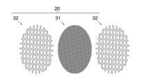
- the valve filter 20 may be formed by stacking multiple mesh filters as shown in FIG. 7.
- the valve filter 20 of this embodiment is formed by sandwiching a first mesh 31 having a fine mesh between a pair of second meshes 32 having a coarser mesh than the first mesh 31.
- the mesh thickness (wire diameter) of the second mesh 32 is formed to be thicker than that of the first mesh 31.
- the inside of the discharge passage 9 is divided into two regions, upstream and downstream.
- the upstream region is the region closer to the inlet 17 than the midpoint between the inlet 17 and the discharge port 18, and the downstream region is the region from the midpoint between the inlet 17 and the discharge port 18 to the discharge port 18.
- the midpoint between the inlet 17 and the discharge port 18 is the position where the distance to the center point C (center of rotation of the crankshaft) of the pump rotor 14 is the same as the distance to the center point D of the discharge port 18 in the side view of the pump cover 7 shown in Figure 4.
- the vicinity of the midpoint between the inlet 17 and the discharge port 18 (the upstream region closer to the downstream, and the downstream region closer to the upstream) may be referred to as the midstream.
- the valve filter 20 is provided on the wall surface of the discharge passage 9 within a range from the midpoint between the inlet 17 and the discharge port 18 to the discharge port 18.
- the valve filter 20 is disposed within a range from the midstream to the downstream of the discharge passage 9.
- the valve filter 20 is also provided within a range of the discharge passage 9 where the flow path cross-sectional area is reduced. In other words, when focusing on the flow path cross-sectional area of the discharge passage 9, the flow path cross-sectional area downstream of the valve filter 20 (the discharge port 18 side) is narrower, and the flow path cross-sectional area upstream of the valve filter 20 (the inlet 17 side) is wider.
- the valve filter 20 is provided at a position higher than the discharge port 18. In other words, the discharge port 18 is located vertically lower than the valve filter 20.
- an inclined surface 24 is provided that slopes toward the downstream of the discharge passage 9.
- the inclined surface 24 is formed on at least the range from the midstream to the downstream of the bottom surface of the discharge passage 9. This ensures a smooth flow of engine oil from the midstream to the downstream of the discharge passage 9.
- the valve filter 20 is also set above the inclined surface 24 so as to be spaced apart from it.
- FIGS. 5 and 6 are cross-sectional views showing a cut surface passing through the valve filter 20.
- FIG. 5 is a cross-sectional view taken along line A-A in FIG. 4
- FIG. 6 is a cross-sectional view taken along line B-B in FIG. 5.
- the valve filter 20 is arranged so that the filter surface is aligned with the flow direction of the engine oil in the discharge passage 9.
- the flow direction of the engine oil flowing from the discharge passage 9 into the sub-passage 11 may be approximately perpendicular to the flow direction of the engine oil in the discharge passage 9, or may be inclined (neither parallel nor perpendicular) to the flow direction of the engine oil in the discharge passage 9.
- the flow direction of engine oil passing through the valve filter 20 is to the right on the page in FIG. 5 (the opposite direction to the chain case 6).
- the movement direction of the valve body of the relief valve 13 is downward on the page in FIG. 5 (vertically downward). In other words, the flow direction of engine oil passing through the valve filter 20 is different from the movement direction of the valve body of the relief valve 13. After passing through the valve filter 20, the engine oil bends downward on the page in FIG. 5 before reaching the relief valve 13.
- the flow direction of engine oil in the discharge passage 9 is perpendicular to the paper (from the back to the front of the paper).
- the filter surface of the valve filter 20 is arranged to form a plane that extends in a direction perpendicular to the paper and in the up-down direction along this flow.
- the flow direction of engine oil in the discharge passage 9 is horizontal (from left to right on the paper).
- the filter surface of the valve filter 20 is arranged to form a plane that extends in a direction perpendicular to the paper and in the up-down direction along this flow.
- the filter surface of the valve filter 20 is flush with the wall surface of the discharge passage 9, or is located inside the discharge passage 9 relative to the wall surface of the discharge passage 9, i.e., toward the center (below the paper in FIG. 6) so that it is exposed to the flow of engine oil in the discharge passage 9.
- the diameter of the valve filter 20 is larger than the diameter of the discharge port 18. That is, if the inner diameter of the valve filter 20 is J and the inner diameter of the discharge port 18 is K, then J>K holds.
- the discharge passage 9 also has a protrusion 19 that protrudes inward from its wall surface.
- the valve filter 20 is provided on this protrusion 19.
- the protrusion 19 is formed, for example, in a shape in which the edge of the entrance of the sub-passage 11 bulges outward toward the inside of the discharge passage 9 in a bank-like shape. In the cross section shown in FIG. 6, if the bulging dimension of the protrusion 19 based on the wall surface of the discharge passage 9 is H, then H>0 holds.
- the portion upstream of the convex portion 19 is formed with a wider flow path width and a larger flow path cross-sectional area than the portion downstream of the convex portion 19. Also, if one focuses on the shape of the discharge passage 9 with reference to the position of the convex portion 19, the portion upstream of the convex portion 19 is formed to be positioned higher than the portion downstream of the convex portion 19.
- the direction in which the engine oil flows from the discharge passage 9 into the sub-passage 11 is the upward direction on the page.
- the direction in which the engine oil flows near the discharge port 18 is also the upward direction on the page, and is approximately parallel to the direction in which the engine oil flows into the sub-passage 11.
- the valve filter 20 is provided on the wall surface of the discharge passage 9 (main passage) that is located on the discharge port 18 side of the pump cover 7. In other words, the discharge port 18 and the valve filter 20 are both provided on the same side of the discharge passage 9, and are positioned on the upper side of the page in FIG. 6 with respect to the discharge passage 9.
- the discharge port 18 is provided at a location where the pump cover 7 bulges out on the opposite side to the chain case 6, and the sub-passage 11 is also provided at a location where the pump cover 7 bulges out on the opposite side to the chain case 6.
- the flow of engine oil in the discharge passage 9 curves leftward in FIG. 6.
- the valve filter 20 is located on the upper wall of the discharge passage 9 in FIG. 6, on the inside of the left curve.
- the engine oil circuit 2 includes a discharge passage 9 (main passage) through which engine oil flows to lubricate sliding parts 23 of the internal combustion engine 1, a sub-passage 11 branched off from a wall surface of the discharge passage 9, a relief valve 13 (valve) disposed in the sub-passage 11 to control the flow rate of engine oil flowing into the sub-passage 11, and a valve filter 20.
- the valve filter 20 is disposed at the entrance of the sub-passage 11 along the wall surface of the discharge passage 9 at a branch point 12 between the discharge passage 9 and the sub-passage 11, and filters out foreign matter contained in the engine oil flowing into the sub-passage 11.
- valve filter 20 at the entrance of the sub-passage 11 along the wall surface of the discharge passage 9, it is possible to prevent contaminants from flowing into the sub-passage 11 when the relief valve 13 is open, and to prevent malfunction of the relief valve 13 due to contamination.
- the relief valve 13 when the relief valve 13 is closed, the contaminants collected on the valve filter 20 can be exposed to the flow of the discharge passage 9, and the contaminants can be pushed downstream of the discharge passage 9. Therefore, with a simple configuration, it is possible to prevent accumulation and clogging of contaminants on the valve filter 20. Note that if an oil filter 21 is provided downstream of the discharge passage 9, the contaminants pushed downstream are collected by the oil filter 21, and malfunction of the sliding parts 23 due to contamination can also be prevented.
- the discharge passage 9 (main passage) and sub-passage 11 are formed in the pump cover 7 that covers the periphery of the pump rotor 14.
- the discharge passage 9 also has an inlet 17 into which engine oil pumped to the pump rotor 14 flows, and a discharge port 18 that is disposed radially outward of the pump rotor 14 from the inlet 17 and discharges the engine oil to the outside of the pump cover 7.
- This simple configuration can prevent malfunction of the relief valve 13 built into the pump cover 7.
- the valve filter 20 is attached to the pump cover 7, it is easy to remove the pump cover 7 to replace or clean the valve filter 20, improving the maintainability of the valve filter 20.
- the discharge passage 9 (main passage) is formed in a shape in which the flow path width narrows from the inlet 17 toward the discharge port 18.
- the valve filter 20 is provided on the wall surface of the discharge passage 9 within a range from the midpoint between the inlet 17 and the discharge port 18 to the discharge port 18.
- the diameter of the valve filter 20 is formed to be larger than the diameter of the discharge port 18.
- the diameter of the valve filter 20 is set to be larger than the diameter of the discharge port 18 according to the flow rate required for the sub-passage 11, and then set the position of the valve filter 20 within the midstream to downstream range so that the valve filter 20 of that diameter fits within the wall surface of the discharge passage 9.
- the discharge port 18 is provided so as to be located vertically below the valve filter 20.
- the contaminants collected on the valve filter 20 can be dropped by its own weight to the discharge port 18 and discharged to the outside of the pump cover 7.
- an inclined surface 24 is provided below the valve filter 20, so that the contaminants can be more reliably pushed toward the discharge port 18. Furthermore, since the position of the valve filter 20 is set above and away from the inclined surface 24, it is possible to prevent the contaminants that have peeled off from the valve filter 20 from reattaching, and it is possible to more reliably push the contaminants toward the discharge port 18.
- the discharge passage 9 (main passage) has a protrusion 19 formed by protruding the wall surface inward from the surrounding area, and the valve filter 20 is provided in the protrusion 19.
- the valve filter 20 is provided closer to the center of the discharge passage 9, the flow rate and flow speed of the engine oil flowing near the valve filter 20 when the relief valve 13 is closed can be increased, and the cleaning action of the valve filter 20 by the engine oil can be enhanced.
- the internal combustion engine 1 to which the engine oil circuit 2 is applied may be a gasoline engine or a diesel engine.
- the internal combustion engine 1 may be mounted not only on automobiles but also on ships, driving force generating devices, power generating devices, etc.
- the automobile When the internal combustion engine 1 is mounted on an automobile, the automobile may be an engine vehicle or a hybrid vehicle.
- a structure in which a valve filter 20 is provided at the branch point 12 between the discharge passage 9 (main passage) and the sub-passage 11 formed in the pump cover 7 has been described in detail, but a similar structure can be applied to other locations besides the pump cover 7.
- any section can be considered as the main passage. It is therefore conceivable to form a sub-passage 11 branching off from this main passage, interpose a valve in the sub-passage 11, and provide a valve filter 20 at the branch point 12 of the sub-passage 11.
- This invention can be used in the manufacturing industry of engine oil circuits applied to internal combustion engines, and the manufacturing industry of internal combustion engines to which engine oil circuits are applied. It can also be used in the manufacturing industry of automobiles, ships, driving force generating devices, power generating devices, etc., which are equipped with internal combustion engines to which engine oil circuits are applied.
Landscapes
- Engineering & Computer Science (AREA)
- Mechanical Engineering (AREA)
- General Engineering & Computer Science (AREA)
- Lubrication Of Internal Combustion Engines (AREA)
Priority Applications (2)
| Application Number | Priority Date | Filing Date | Title |
|---|---|---|---|
| JP2025556046A JPWO2025099798A1 (https=) | 2023-11-06 | 2023-11-06 | |
| PCT/JP2023/039885 WO2025099798A1 (ja) | 2023-11-06 | 2023-11-06 | エンジンオイル回路 |
Applications Claiming Priority (1)
| Application Number | Priority Date | Filing Date | Title |
|---|---|---|---|
| PCT/JP2023/039885 WO2025099798A1 (ja) | 2023-11-06 | 2023-11-06 | エンジンオイル回路 |
Publications (1)
| Publication Number | Publication Date |
|---|---|
| WO2025099798A1 true WO2025099798A1 (ja) | 2025-05-15 |
Family
ID=95695139
Family Applications (1)
| Application Number | Title | Priority Date | Filing Date |
|---|---|---|---|
| PCT/JP2023/039885 Pending WO2025099798A1 (ja) | 2023-11-06 | 2023-11-06 | エンジンオイル回路 |
Country Status (2)
| Country | Link |
|---|---|
| JP (1) | JPWO2025099798A1 (https=) |
| WO (1) | WO2025099798A1 (https=) |
Citations (5)
| Publication number | Priority date | Publication date | Assignee | Title |
|---|---|---|---|---|
| JPH0234778U (https=) * | 1988-08-30 | 1990-03-06 | ||
| JP2013204516A (ja) * | 2012-03-28 | 2013-10-07 | Honda Motor Co Ltd | オイルポンプを備えたエンジン |
| US20140261280A1 (en) * | 2013-03-13 | 2014-09-18 | Honda Motor Co., Ltd. | Active pressure relief valve system and method |
| JP2016098878A (ja) * | 2014-11-19 | 2016-05-30 | アイシン精機株式会社 | リリーフバルブ |
| JP2020073807A (ja) * | 2017-03-08 | 2020-05-14 | 日立オートモティブシステムズ株式会社 | バランサ装置とオイルポンプ及びバランサシャフト軸受部の潤滑システム |
-
2023
- 2023-11-06 WO PCT/JP2023/039885 patent/WO2025099798A1/ja active Pending
- 2023-11-06 JP JP2025556046A patent/JPWO2025099798A1/ja active Pending
Patent Citations (5)
| Publication number | Priority date | Publication date | Assignee | Title |
|---|---|---|---|---|
| JPH0234778U (https=) * | 1988-08-30 | 1990-03-06 | ||
| JP2013204516A (ja) * | 2012-03-28 | 2013-10-07 | Honda Motor Co Ltd | オイルポンプを備えたエンジン |
| US20140261280A1 (en) * | 2013-03-13 | 2014-09-18 | Honda Motor Co., Ltd. | Active pressure relief valve system and method |
| JP2016098878A (ja) * | 2014-11-19 | 2016-05-30 | アイシン精機株式会社 | リリーフバルブ |
| JP2020073807A (ja) * | 2017-03-08 | 2020-05-14 | 日立オートモティブシステムズ株式会社 | バランサ装置とオイルポンプ及びバランサシャフト軸受部の潤滑システム |
Also Published As
| Publication number | Publication date |
|---|---|
| JPWO2025099798A1 (https=) | 2025-05-15 |
Similar Documents
| Publication | Publication Date | Title |
|---|---|---|
| JP2507024B2 (ja) | エンジンのケ―シング装置 | |
| CN102121415B (zh) | 用于具有涡轮增压器的发动机的润滑装置 | |
| US10851685B2 (en) | Balancer device and lubricating system for oil pump and balancer shaft bearing | |
| US6880512B2 (en) | Balancer device for engine | |
| CN106414924A (zh) | 凸轮轴调节设备 | |
| CA2676572C (en) | Oil strainer structure of engine and oil return structure of engine | |
| EP3135873B1 (en) | Internal combustion engine and oil treatment apparatus for use with the same | |
| CN1126797A (zh) | 内燃机润滑系统 | |
| WO2025099798A1 (ja) | エンジンオイル回路 | |
| WO2025100039A1 (ja) | エンジンオイル回路 | |
| JP2001342816A (ja) | 内燃機関の潤滑装置 | |
| JP2003193816A (ja) | 内燃機関のためのオイル捕集装置およびオイルポンプ | |
| CN1254603C (zh) | 内燃机油泵 | |
| JP2006266235A (ja) | 内燃機関の潤滑装置 | |
| EP3333426B1 (en) | Variable pump | |
| CN101191444A (zh) | 内燃机前罩盖 | |
| JP6485305B2 (ja) | 可変オイルポンプ | |
| JP2012193711A (ja) | 内燃機関の潤滑装置 | |
| JP4066677B2 (ja) | エンジンの潤滑装置 | |
| KR200311749Y1 (ko) | 차량용 기어식 오일펌프 | |
| CN103899430A (zh) | 一种汽车发动机的前罩壳 | |
| JP2009097366A (ja) | エンジンのオイル供給装置 | |
| US20180223706A1 (en) | Lubrication structure for internal combustion engine | |
| JP4711911B2 (ja) | エンジンのオイルストレーナ構造 | |
| JP2010285884A (ja) | エンジンの潤滑装置 |
Legal Events
| Date | Code | Title | Description |
|---|---|---|---|
| 121 | Ep: the epo has been informed by wipo that ep was designated in this application |
Ref document number: 23956992 Country of ref document: EP Kind code of ref document: A1 |
|
| ENP | Entry into the national phase |
Ref document number: 2025556046 Country of ref document: JP Kind code of ref document: A |
|
| WWE | Wipo information: entry into national phase |
Ref document number: 2025556046 Country of ref document: JP |
|
| WWE | Wipo information: entry into national phase |
Ref document number: 2501008945 Country of ref document: TH |