WO2025099786A1 - 内燃機関 - Google Patents
内燃機関 Download PDFInfo
- Publication number
- WO2025099786A1 WO2025099786A1 PCT/JP2023/039798 JP2023039798W WO2025099786A1 WO 2025099786 A1 WO2025099786 A1 WO 2025099786A1 JP 2023039798 W JP2023039798 W JP 2023039798W WO 2025099786 A1 WO2025099786 A1 WO 2025099786A1
- Authority
- WO
- WIPO (PCT)
- Prior art keywords
- internal combustion
- combustion engine
- front cover
- engine body
- mount bracket
- Prior art date
- Legal status (The legal status is an assumption and is not a legal conclusion. Google has not performed a legal analysis and makes no representation as to the accuracy of the status listed.)
- Pending
Links
Images



Classifications
-
- B—PERFORMING OPERATIONS; TRANSPORTING
- B60—VEHICLES IN GENERAL
- B60K—ARRANGEMENT OR MOUNTING OF PROPULSION UNITS OR OF TRANSMISSIONS IN VEHICLES; ARRANGEMENT OR MOUNTING OF PLURAL DIVERSE PRIME-MOVERS IN VEHICLES; AUXILIARY DRIVES FOR VEHICLES; INSTRUMENTATION OR DASHBOARDS FOR VEHICLES; ARRANGEMENTS IN CONNECTION WITH COOLING, AIR INTAKE, GAS EXHAUST OR FUEL SUPPLY OF PROPULSION UNITS IN VEHICLES
- B60K5/00—Arrangement or mounting of internal-combustion or jet-propulsion units
- B60K5/12—Arrangement of engine supports
-
- F—MECHANICAL ENGINEERING; LIGHTING; HEATING; WEAPONS; BLASTING
- F02—COMBUSTION ENGINES; HOT-GAS OR COMBUSTION-PRODUCT ENGINE PLANTS
- F02B—INTERNAL-COMBUSTION PISTON ENGINES; COMBUSTION ENGINES IN GENERAL
- F02B77/00—Component parts, details or accessories, not otherwise provided for
- F02B77/11—Thermal or acoustic insulation
- F02B77/13—Acoustic insulation
Definitions
- the present invention relates to an internal combustion engine mounted on a vehicle.
- a chain case front cover that covers the timing chain that transmits the rotational force of the crankshaft to the camshaft.
- Patent Document 1 discloses a metal chain case with an integrated support bracket in which a chain cover section and a support bracket section for fixing an engine mount, which is a part for suspending the engine from the vehicle body, are integrally formed.
- the chain case in Patent Document 1 is made of metal and helps ensure the rigidity of the front end of the internal combustion engine.
- the internal combustion engine of the present invention comprises a resin front cover that covers one end face in the cylinder row direction of an internal combustion engine body having a cylinder head and a cylinder block, and a metal mounting bracket that is located at one end side in the cylinder row direction of the internal combustion engine body, is arranged to straddle the outside of the front cover, and mounts the internal combustion engine body to a vehicle. Both side portions of the mounting bracket in the width direction of the internal combustion engine body are fixed to both the cylinder head and the cylinder block, respectively.
- both sides of the mounting bracket are fixed to both the cylinder head and the cylinder block at different fastening points, so the rigidity of one end of the internal combustion engine body in the direction of the cylinder row can be ensured.
- FIG. 4 is an exploded perspective view of the front cover and the internal combustion engine side mount bracket.
- FIG. 11 is an explanatory diagram showing a schematic diagram of another embodiment of the present invention.
- the X-axis indicates an axis along the front-rear direction of the internal combustion engine 1 (axis parallel to the central axis of the crankshaft 19 of the internal combustion engine 1)
- the Y-axis indicates an axis along the left-right direction (width direction of the internal combustion engine) of the internal combustion engine 1
- the Z-axis indicates an axis along the up-down direction of the internal combustion engine 1 (axis parallel to the cylinder axis L1 of the internal combustion engine 1).
- the X-axis is an axis along the cylinder row direction of the internal combustion engine 1 or the internal combustion engine body 8 (described later).
- the Y-axis is an axis along the width direction of the internal combustion engine body 8.
- FIG. 1 is an explanatory diagram showing a schematic configuration of an internal combustion engine 1 to which the present invention is applied.
- the internal combustion engine 1 is, for example, an in-line multi-cylinder internal combustion engine, and has a cylinder head 2, a cylinder block 3 attached to the bottom of the cylinder head 2, a cam bracket 4 attached to the top of the cylinder head 2, a front cover 5 that covers the front of the internal combustion engine body 8, and an internal combustion engine side mount bracket 6 that is a metal mount bracket located in front of the front cover 5.
- reference numeral 7 in FIG. 1 denotes a vehicle side mount bracket that is fixed to the vehicle body.
- the cylinder head 2, cylinder block 3, and cam bracket 4 constitute the internal combustion engine body 8. Therefore, the front cover 5 covers one end face of the internal combustion engine body 8 in the cylinder row direction.
- the cylinder head 2 is a casting made of a metal material such as an aluminum alloy, and is formed with an intake port (not shown) that supplies intake air to the combustion chamber (not shown), and an exhaust port (not shown) that discharges exhaust gas from the combustion chamber (not shown).
- the cylinder block 3 is a casting made of a metal material such as an aluminum alloy, and has a number of cylinders (not shown) corresponding to the number of cylinders.
- the cam bracket 4 is made of a metal material such as an aluminum alloy, and supports the camshaft 10 (see Figure 2) so that it can rotate together with the cylinder head 2.
- the front cover 5 is made of a synthetic resin material such as polyamide, and is attached liquid-tight to the internal combustion engine body 8 so as to cover the front surface of the internal combustion engine body 8. More specifically, the front cover 5 is attached to the front surface of the cylinder block 3, the front surface of the cylinder head 2, the front surface of the cam bracket 4, etc., with bolts (not shown). In other words, the front cover 5 is attached to the internal combustion engine body 8 so as to cover the end faces on one end side of the cylinder block 3 and the cylinder head 2 in the crankshaft axial direction, i.e., the end face 8a on one end side of the internal combustion engine body 8 in the cylinder row direction.
- a synthetic resin material such as polyamide
- the front cover 5 has a shallow dish shape, and forms a space 9 between the front surface of the internal combustion engine body 8, which is the end face of one end of the internal combustion engine body 8 in the cylinder row direction, to accommodate the rotational power transmission mechanism.
- FIG. 2 is an explanatory diagram showing a schematic plan view of one end of the internal combustion engine 1 in the cylinder row direction.
- the space 9 accommodates a crank sprocket (not shown) fixed to the crankshaft 19 (see FIG. 4) and a cam sprocket 11 fixed to the front end of the camshaft 10.
- a timing chain (not shown) for transmitting rotational power is wound around the crank sprocket and the cam sprocket 11.
- the space 9 formed between the front cover 5 and the internal combustion engine body 8 is an environment that contains a timing chain that performs oil lubrication.
- the space 9 is liquid-tight from the outside because the space between the front cover 5 and the internal combustion engine body 8 is sealed liquid-tight.
- An intake cam sprocket 11a is attached to the front end of the intake camshaft 10a.
- An exhaust cam sprocket 11b and a phase variable mechanism 12 are attached to the front end of the exhaust camshaft 10b.
- the phase variable mechanism 12 is a variable valve mechanism that changes the phase of the lift central angle of the exhaust valve, which serves as an engine valve, to change the valve timing of the exhaust valve.
- phase variable mechanism 12 is covered by the front cover 5 above the internal combustion engine side mount bracket 6 in the vertical direction along the cylinder axis L1 (see FIG. 4 described later) of the internal combustion engine 1.
- the front cover 5 is formed with a boss through hole 13, a crankshaft through hole 14, a first bolt through hole 15, a second bolt through hole 16, and a gauge insertion hole 50.
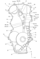
- Figure 3 is a front view of the front cover 5.
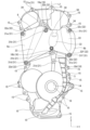
- Figure 4 is a front view of the internal combustion engine 1 with the internal combustion engine side mount bracket 6 attached.
- the boss through-holes 13 are formed in two locations in the center of the front cover 5 in the width direction of the internal combustion engine body 8, through which the bolt bosses 32 (see FIG. 5) of the internal combustion engine side mount bracket 6 pass.
- the outer periphery of the boss through-holes 13 is an annular (cylindrical) through-hole periphery (bolt through-hole periphery) 17.
- the through-hole periphery 17 is pressed against and contacts the end face of one end of the internal combustion engine body 8 in the cylinder row direction on the back side of the front cover 5, supporting the center of the front cover 5 on the internal combustion engine body 8.
- the through-hole periphery 17 and the internal combustion engine body 8 are sealed liquid-tight by a seal member (not shown).
- the periphery of the second bolt through-hole 16 and the internal combustion engine body 8 are sealed liquid-tight by a seal member (not shown).
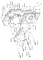
- Figure 5 is an exploded perspective view of the front cover 5 and the internal combustion engine side mounting bracket 6 that are attached to the internal combustion engine body 8.
- the boss through hole 13b is located below the boss through hole 13a, and the fifth bolt boss 32e passes through it as shown in FIG. 5.
- a through hole periphery 17b is formed around the boss through hole 13b. The through hole periphery 17b is pressed against the cylinder block 3 on the back side of the front cover 5.
- crankshaft through hole 14 through which the crankshaft 19 passes, is formed below the boss through hole 13.
- the periphery of the crankshaft through hole 14 is sealed liquid-tight.
- the first bolt through holes 15 are formed on the outer periphery of the front cover 5, through which bolts (not shown) that secure the front cover 5 to the internal combustion engine body 8 pass.
- the outer periphery of the front cover 5 is liquid-tightly sealed all around by an annular outer periphery seal material (not shown).
- the outer periphery seal material is located on the inner side of the first bolt through holes 15.
- the second bolt through-hole 16 is for receiving a fixing bolt (not shown) that fixes the front cover 5 to the internal combustion engine body 8, and is formed in the front cover boss portion 21.
- the front cover boss portion 21 is fixed on the back side of the front cover 5 with its tip surface pressed against the end surface of one end of the internal combustion engine body 8 in the cylinder row direction.
- Front cover boss portion 21a is fixed on the back side of front cover 5 with its tip surface pressed against cylinder head 2.
- Front cover boss portions 21b, 21c, and 21d are fixed on the back side of front cover 5 with their tip surfaces pressed against cylinder block 3.
- the front cover boss portion 21a is formed adjacent to and continuous with the through hole peripheral portion 17a.
- the front cover boss portion 21a has a second bolt through hole 16a formed therein.
- Front cover boss portion 21b is formed adjacent to and continuous with through hole peripheral portion 17b.
- a second bolt through hole 16b is formed in front cover boss portion 21b.
- Front cover boss portion 21c is formed so as to be positioned between through hole peripheral portion 17a and through hole peripheral portion 17b in the vertical direction (direction along the Z axis) of front cover 5.
- front cover boss portion 21c is formed in a portion of front cover 5 that is covered by internal combustion engine side mount bracket 6.
- a second bolt through hole 16c is formed in front cover boss portion 21c.
- Front cover boss portion 21d is formed so as to be located below through-hole periphery portion 17b in the vertical direction (direction along the Z axis) of front cover 5.
- front cover boss portion 21d is formed in a portion of front cover 5 that is not covered by internal combustion engine side mount bracket 6.
- a second bolt through-hole 16d is formed in front cover boss portion 21d.
- the gauge insertion port 50 is a hole formed through the top of the front cover 5 into which an oil level gauge (not shown) is inserted.
- the internal combustion engine side mount bracket 6 is attached to one end face of the internal combustion engine body 8 in the cylinder row direction without contacting the front cover 5.
- the internal combustion engine side mount bracket 6 is a casting made of a metal material such as an aluminum alloy, and is a member for mounting the internal combustion engine body 8 (internal combustion engine 1) to the vehicle.
- the internal combustion engine side mounting bracket 6 is attached to the end faces of the cylinder head 2 and one end of the cylinder block 3 by six bolts 31, the first bolt 31a to the sixth bolt 31f.
- the bolts 31 pass through the bolt boss portions 32 of the internal combustion engine side mounting bracket 6.
- the internal combustion engine side mount bracket 6 is formed so that its length along the width direction of the internal combustion engine body 8 is longer than that of the front cover 5. As shown in Figures 2 and 4, the internal combustion engine side mount bracket 6 is attached to the internal combustion engine body 8, overlapping with the front cover 5 in the cylinder row direction of the internal combustion engine body 8 with a specified gap so as to cover part of the outer surface of the front cover 5. In other words, the internal combustion engine side mount bracket 6 is attached to the internal combustion engine body 8 so as not to come into contact with the front cover 5.
- the internal combustion engine side mount bracket 6 is formed so that its length along the width direction of the internal combustion engine body 8 is longer than the length of the front cover 5 along the width direction of the internal combustion engine body 8, at least in the range where it overlaps with the mount bracket 6.
- the internal combustion engine side mounting bracket 6 straddles the outside of the front cover 5 in the width direction of the front cover 5 (the direction along the Y axis) and is fixed to the internal combustion engine body 8 on both sides of the front cover 5.
- the upper edge of the internal combustion engine side mount bracket 6 in the vertical direction along the cylinder axis L1 of the internal combustion engine 1 is fixed to the internal combustion engine body 8 by the first bolt 31a to the third bolt 31c.
- the lower edge of the internal combustion engine side mount bracket 6 in the vertical direction along the cylinder axis L1 of the internal combustion engine 1 is fixed to the internal combustion engine body 8 by the fourth bolt 31d to the sixth bolt 31f.
- both ends of the upper edge of the engine side mount bracket 6 in the width direction of the engine body 8 are fixed to the engine body 8 by a first bolt 31a and a third bolt 31c on the outside of the front cover 5.
- the upper edge of the engine side mount bracket 6 is fixed to the engine body 8 by a second bolt 31b that passes through the front cover 5 at the center in the width direction of the engine body 8.
- the lower edge of the internal combustion engine side mount bracket 6 is fixed to the internal combustion engine body 8 at both ends in the width direction by the fourth bolt 31d and the sixth bolt 31f on the outside of the front cover 5.
- the lower edge of the internal combustion engine side mount bracket 6 is fixed to the internal combustion engine body 8 at the center in the width direction by the fifth bolt 31e that passes through the front cover 5.
- the internal combustion engine side mount bracket 6 has six bolt boss portions 32, the first bolt boss portion 32a to the sixth bolt boss portion 32f.
- the internal combustion engine side mount bracket 6 does not come into contact with the front cover 5, and these six bolt boss portions 32 do not come into contact with the front cover 5.
- the first bolt 31a secures the upper portion of one end of the internal combustion engine side mount bracket 6 in the width direction of the internal combustion engine to the cylinder head 2 outside the front cover 5.
- the first bolt 31a passes through the first bolt boss portion 32a of the internal combustion engine side mount bracket 6.
- the first bolt boss portion 32a is formed on one end of the internal combustion engine side mount bracket 6 in the width direction of the internal combustion engine body 8.
- the second bolt 31b passes through the front cover 5 and secures the upper part of the internal combustion engine side mount bracket 6, approximately at the center in the width direction of the internal combustion engine, to the cylinder head 2.
- the second bolt 31b passes through the second bolt boss portion 32b of the internal combustion engine side mount bracket 6.
- the second bolt boss portion 32b is formed in the central portion of the internal combustion engine side mount bracket 6 in the width direction of the internal combustion engine body 8.
- the second bolt boss portion 32b passes through the boss through hole 13a so that its outer peripheral surface does not come into contact with the inner peripheral surface of the boss through hole 13a of the front cover 5.
- the tip portion of the second bolt boss portion 32b on the back side of the front cover 5 is pressed against the cylinder head 2.
- the front cover boss portion 21a adjacent to the boss through hole 13a is fixed to the cylinder head 2 by a fixing bolt (not shown).
- the third bolt 31c secures the upper portion of the other end of the internal combustion engine side mount bracket 6 in the width direction of the internal combustion engine to the cylinder head 2 outside the front cover 5.
- the third bolt 31c passes through the third bolt boss portion 32c of the internal combustion engine side mount bracket 6.
- the third bolt boss portion 32c is formed on the other end of the internal combustion engine side mount bracket 6 in the width direction of the internal combustion engine body 8.
- the fourth bolt 31d secures the lower portion of one end of the internal combustion engine side mount bracket 6 in the width direction of the internal combustion engine to the cylinder block 3 outside the front cover 5.
- the fourth bolt 31d passes through the fourth bolt boss portion 32d of the internal combustion engine side mount bracket 6.
- the fourth bolt boss portion 32d is formed on one end of the internal combustion engine side mount bracket 6 in the width direction of the internal combustion engine body 8.
- the fifth bolt 31e passes through the front cover 5 and secures the lower part of the internal combustion engine side mount bracket 6, approximately at the center in the width direction of the internal combustion engine, to the cylinder block 3.
- the fifth bolt 31e passes through the fifth bolt boss portion 32e of the internal combustion engine side mount bracket 6.
- the fifth bolt boss portion 32e is formed in the central portion of the internal combustion engine side mount bracket 6 in the width direction of the internal combustion engine body 8.
- the fifth bolt boss portion 32e passes through the boss portion through hole 13b so that its outer peripheral surface does not come into contact with the inner peripheral surface of the boss portion through hole 13b of the front cover 5.
- the tip portion of the fifth bolt boss portion 32e on the back side of the front cover 5 is pressed against the cylinder block 3.
- the front cover boss portion 21b adjacent to the boss portion through hole 13b is fixed to the cylinder block 3 by a fixing bolt (not shown).
- the sixth bolt 31f secures the lower part of the other end of the internal combustion engine side mount bracket 6 in the width direction of the internal combustion engine to the cylinder block 3 outside the front cover 5.
- the sixth bolt 31f passes through the sixth bolt boss portion 32f of the internal combustion engine side mount bracket 6.
- the sixth bolt boss portion 32f is formed on the other end of the internal combustion engine side mount bracket 6 in the width direction of the internal combustion engine body 8.
- the internal combustion engine side mounting bracket 6 has multiple (three) mounting portions 33, as shown in Figures 4 and 5.
- the mount portion 33 is used to attach the internal combustion engine 1 to the vehicle body, and its upper end surface 34 is fixed to the vehicle body side mount bracket 7 with a bolt (not shown).
- the mount portion 33 is composed of a bulging portion with a semi-cylindrical cross section that protrudes forward from the end surface 8a on one end side of the internal combustion engine main body 8. In other words, the back side of the mount portion 33 is hollowed out.
- the mount portion 33 is formed so as to extend in the vertical direction along the cylinder axis L1 of the internal combustion engine 1. In other words, the mount portion 33 is elongated in the vertical direction, and its upper end surface 34 is fixed to the vehicle body side mount bracket 7.
- the one end 6a and the other end 6b which are both sides of the internal combustion engine body 8 in the width direction (direction along the Y axis) of the internal combustion engine side mount bracket 6, are individually fixed to both the cylinder head 2 and the cylinder block 3 by bolts 31, which are fastening elements.
- the upper part of the end 6a (one end side) of the internal combustion engine side mount bracket 6, which is the left side in FIG. 4 in the left-right direction along the width direction (direction along the Y axis) of the internal combustion engine body 8, is fixed to the cylinder head 2 by the first bolt 31a.
- the lower part of the end 6a (one end side) of the internal combustion engine side mount bracket 6, which is the left side in FIG. 4 in the left-right direction along the width direction (direction along the Y axis) of the internal combustion engine body 8 is fixed to the cylinder block 3 by the fourth bolt 31d.
- the upper part of the other end 6b (other end side) of the internal combustion engine side mount bracket 6, which is on the right side in FIG. 4 in the left-right direction along the width direction (direction along the Y axis) of the internal combustion engine body 8, is fixed to the cylinder head 2 by a third bolt 31c.
- the lower part of the other end 6b (other end side) of the internal combustion engine side mount bracket 6, which is on the right side in FIG. 4 in the left-right direction along the width direction (direction along the Y axis) of the internal combustion engine body 8, is fixed to the cylinder block 3 by a sixth bolt 31f.
- the front cover 5 is attached to the end face of one end of the internal combustion engine body 8 in the cylinder row direction, and contributes to the rigidity of that end of the internal combustion engine body 8. For example, even if the force transmitted from the rotational power transmission mechanism to the internal combustion engine body at the front end of the internal combustion engine deforms the front end side of the internal combustion engine body or acts in a direction that weakens the fastening force between the cylinder block and the cylinder head (promoting misalignment and opening between the fastening members), if the front cover fixed to the cylinder block and the cylinder head is made of metal, it acts as reinforcement, suppressing such deformation and reduction in fastening force (misalignment and opening between the fastening members), and contributing to improving the rigidity of the internal combustion engine body.
- the rigidity of one end of the internal combustion engine body 8 in the direction of the cylinder row is reduced compared to when the front cover 5 is made of metal.
- both sides of the internal combustion engine side mount bracket 6, which is positioned so as to straddle the front cover 5, are fixed to the cylinder head 2 and the cylinder block 3, respectively, so that the reduction in rigidity at one end of the cylinder row direction of the internal combustion engine body 8, which is a concern when the front cover 5 is made of resin instead of metal, can be suppressed.
- the internal combustion engine 1 has both side portions (one end 6a and the other end 6b) of the engine-side mount bracket 6 fixed to both the cylinder head 2 and the cylinder block 3 at different fastening points, so the rigidity of one end of the internal combustion engine body 8 in the cylinder row direction can be ensured.
- the internal combustion engine 1 is arranged so that the internal combustion engine side mount bracket 6 straddles the front cover 5, and the internal combustion engine side mount bracket 6 is unlikely to interfere with the front cover 5, improving the design freedom of the front cover 5.
- the internal combustion engine side mount bracket 6 is set to a length along the width direction of the internal combustion engine body 8 so that it can straddle the front cover 5, so that the length along the width direction (width) of the internal combustion engine body 8 can be set to be long, which is advantageous in ensuring the rigidity of one end side of the internal combustion engine body 8 in the cylinder row direction.
- one end 6a and the other end 6b which are both widthwise portions of the internal combustion engine body 8 of the internal combustion engine side mounting bracket 6, are fixed to the cylinder head 2 and the cylinder block 3 at separate fastening points, so that the occurrence of vibrations that cause the cylinder head 2 and the cylinder block 3 to open up at one end in the cylinder row direction can be suppressed.
- the internal combustion engine 1 has a front cover 5 made of resin, which has a lower rigidity than a metal cover, by making the internal combustion engine side mount bracket 6 out of metal, which has a higher rigidity, it is possible to reduce the amplitude of vibration transmitted from the internal combustion engine body to the internal combustion engine side mount bracket 6.
- the engine-side mount bracket 6 is a member that extends continuously in a strip along the width direction of the engine body 8, and the width dimension of the engine-side mount bracket 6 that extends in a strip is longer than the height dimension of the engine body when viewed from the front.
- the engine-side mount bracket 6 overlaps so as to cover part of the outer surface of the front cover 5, and multiple points on its outer periphery are fixed to the engine body 8.
- the external surface of the front cover 5 of the internal combustion engine 1 is covered in a strip-like shape by the internal combustion engine side mount bracket 6, so that the noise emitted from the surface of the front cover 5 is blocked by the internal combustion engine side mount bracket 6, thereby reducing the noise radiated from the front cover 5, which is a major contributor to engine noise.
- the internal combustion engine 1 has both sides of the engine-side mount bracket 6 in the width direction of the internal combustion engine body 8 fixed to the outer periphery (outer periphery) of the end face on one end side of the internal combustion engine body 8.
- the length of the engine-side mount bracket 6 along the width direction of the engine body 8 of the internal combustion engine 1 can be set to its maximum length, so that the engine 1 can effectively resist various forces and twists on one end of the engine body 8.
- the internal combustion engine 1 is lubricated with lubricating oil between the front cover 5 and the internal combustion engine body 8.
- the internal combustion engine 1 has an internal combustion engine side mount bracket 6 that straddles the front cover 5 and is attached to the internal combustion engine body 8, so that a liquid-tight space 9 can be easily formed between the front cover 5 and the internal combustion engine body 8, and the deformation mode of the cylinder head 2 and cylinder block 3 can be suppressed to improve the sealing of the liquid-tight space 9 between the front cover 5 and the internal combustion engine body 8.
- the internal combustion engine 1 may employ an internal combustion engine side mount bracket 41 made of resin and having a generally X-shape as shown in FIG. 6.
- This internal combustion engine side mount bracket 41 like the internal combustion engine side mount bracket 6 described above, is positioned so as to straddle the front cover 5, and one end 42 and the other end 43, which are both sides of the internal combustion engine side mount bracket 41 in the width direction (direction along the Y axis) of the internal combustion engine body 8, are individually fixed to both the cylinder head 2 and the cylinder block 3 by bolts 44, which are fastening elements.
- the upper end 42a is fixed to the cylinder head 2 by bolts 44a.
- the lower end 42b is fixed to the cylinder block 3 by bolts 44b.
- the other upper end 43a is fixed to the cylinder head 2 by bolts 44c.
- the other lower end 43b is fixed to the cylinder block 3 by bolts 44d.
- the internal combustion engine side mount bracket 41 shown in FIG. 6 is fixed to the internal combustion engine body 8 by four bolts 44.
- the internal combustion engine side mount bracket 41 shown in FIG. 6 has an X-shape and does not cover the outer surface of the front cover 5 in a continuous band-like shape, but both side portions in the width direction (direction along the Y axis) of the internal combustion engine body 8 are fixed at different fastening points to both the cylinder head 2 and the cylinder block 3 by bolts 44, so the rigidity of one end of the internal combustion engine body 8 in the cylinder row direction can be ensured.
Landscapes
- Engineering & Computer Science (AREA)
- Physics & Mathematics (AREA)
- Acoustics & Sound (AREA)
- Chemical & Material Sciences (AREA)
- Combustion & Propulsion (AREA)
- Mechanical Engineering (AREA)
- General Engineering & Computer Science (AREA)
- Transportation (AREA)
- Cylinder Crankcases Of Internal Combustion Engines (AREA)
Abstract
内燃機関(1)は、シリンダヘッド(2)及びシリンダブロック(3)を有する内燃機関本体(8)の気筒列方向の一端側の端面を覆う樹脂製のフロントカバー(5)と、内燃機関本体(8)の気筒列方向の一端側に位置し、フロントカバー(5)の外側を跨ぐように配置され、内燃機関本体(8)を車両に対して取り付ける金属製の内燃機関側マウントブラケット(6)と、を備えている。内燃機関側マウントブラケット(6)は、内燃機関本体(8)の幅方向における両側部分が、それぞれシリンダヘッド(2)及びシリンダブロック(3)の両方に対して固定されている。
Description
本発明は、車両に搭載される内燃機関に関する。
内燃機関の気筒列方向の一端側は、クランクシャフトの回転力をカムシャフトに伝達するタイミングチェーンを覆うようにチェーンケース(フロントカバー)で覆われている。
例えば、特許文献1には、チェーンカバー部とエンジンを車体に吊り下げるための部品であるエンジンマウントを固定するためにサポートブラケット部とが一体に形成されたサポートブラケット一体型の金属製のチェーンケースが開示されている。特許文献1のチェーンケースは、金属製であり、内燃機関の前端の剛性確保に寄与している。
しかしながら、特許文献1のチェーンケースは、金属製のため、内燃機関の重量を増加させるという問題がある。
つまり、チェーンケースを有する内燃機関は、内燃機関の前端の剛性を確保しつつ、軽量化を図る上で更なる改善の余地がある。
本発明の内燃機関は、シリンダヘッド及びシリンダブロックを有する内燃機関本体の気筒列方向の一端側の端面を覆う樹脂製のフロントカバーと、上記内燃機関本体の気筒列方向の一端側に位置し、上記フロントカバーの外側を跨ぐように配置され、上記内燃機関本体を車両に対して取り付ける金属製のマウントブラケットと、を備えている。上記マウントブラケットは、上記内燃機関本体の幅方向における両側部分が、それぞれ上記シリンダヘッド及び上記シリンダブロックの両方に固定されている。
内燃機関は、マウントブラケットの両側部分がそれぞれシリンダヘッドとシリンダブロックの双方に対して異なる止め点で固定されているので、内燃機関本体の気筒列方向の一端側の剛性を確保することができる。
以下、本発明の一実施例を図面に基づいて詳細に説明する。なお、各図中におけるX軸は内燃機関1の前後方向に沿った軸線(内燃機関1のクランクシャフト19の中心軸と平行な軸線)、Y軸は内燃機関1の左右方向(内燃機関幅方向)に沿った軸線、Z軸は内燃機関1の上下方向に沿った軸線(内燃機関1のシリンダ軸線L1と平行な軸線)、をそれぞれ示している。つまりX軸は、内燃機関1あるいは内燃機関本体8(後述)の気筒列方向に沿った軸線である。また、Y軸は、内燃機関本体8の幅方向に沿った軸線である。
図1は、本発明が適用される内燃機関1の概略構成を模式的に示した説明図である。
内燃機関1は、例えば直列多気筒の内燃機関であって、シリンダヘッド2と、シリンダヘッド2の下部に取り付けられたシリンダブロック3と、シリンダヘッド2の上部に取り付けられたカムブラケット4と、内燃機関本体8の前面を覆うフロントカバー5と、フロントカバー5の前面に位置する金属製のマウントブラケットとしての内燃機関側マウントブラケット6と、を有している。なお、図1中の符号7は、車体側に固定された車体側マウントブラケットである。シリンダヘッド2、シリンダブロック3及びカムブラケット4は、内燃機関本体8を構成するものである。従って、フロントカバー5は、内燃機関本体8の気筒列方向の一端側の端面を覆っている。
シリンダヘッド2は、例えばアルミ合金等の金属材料からなる鋳造品であり、燃焼室(図示せず)に吸気を供給する吸気ポート(図示せず)や、燃焼室(図示せず)から排気を排出するための排気ポート(図示せず)が形成されている。
シリンダブロック3は、例えばアルミ合金等の金属材料からなる鋳造品であり、気筒数に応じた数のシリンダ(図示せず)が形成されている。
カムブラケット4は、例えばアルミ合金等の金属材料からなり、カムシャフト10(図2を参照)をシリンダヘッド2とともに回転可能に支持するものである。
フロントカバー5は、例えばポリアミド等の合成樹脂材料からなり、内燃機関本体8の前面を覆うように内燃機関本体8に液密に取り付けられている。詳述すると、フロントカバー5は、シリンダブロック3の前面、シリンダヘッド2の前面及びカムブラケット4の前面等に、図示せぬボルトによって取り付けられている。換言すると、フロントカバー5は、クランクシャフト軸線方向におけるシリンダブロック3及びシリンダヘッド2の一端側の端面、つまり内燃機関本体8の気筒列方向の一端側の端面8aを覆うように内燃機関本体8に取り付けられる。
図2に示すように、フロントカバー5は、浅皿形状を呈し、内燃機関本体8の気筒列方向の一端側の端面である内燃機関本体8の前面との間に空間9を形成して回転動力伝達機構を収容する。図2は、内燃機関1の気筒列方向の一端側を平面視して模式的に示した説明図である。空間9には、クランクシャフト19(図4を参照)に固定されたクランクスプロケット(図示せず)や、カムシャフト10の前端に固定されたカムスプロケット11が収容される。これらクランクスプロケット及びカムスプロケット11には、回転動力伝達用のタイミングチェーン(図示せず)が巻き掛けられる。フロントカバー5と内燃機関本体8との間に形成される空間9は、油潤滑を行うタイミングチェーンを有する環境である。空間9は、フロントカバー5と内燃機関本体8との間が液密にシールされことにより、外部に対して液密となっている。
吸気カムシャフト10aの前端には、吸気カムスプロケット11aが取り付けられている。排気カムシャフト10bの前端には、排気カムスプロケット11bと位相可変機構12が取り付けられている。位相可変機構12は、機関弁としての排気弁のリフト中心角の位相を変更して排気弁のバルブタイミングを変更する可変動弁機構である。
位相可変機構12は、内燃機関1のシリンダ軸線L1(後述する図4を参照)に沿った上下方向で、内燃機関側マウントブラケット6よりも上方側でフロントカバー5に覆われている。
図3及び図4に示すように、フロントカバー5には、ボス部貫通孔13と、クランクシャフト貫通孔14と、第1ボルト貫通孔15と、第2ボルト貫通孔16と、ゲージ差し込み口50と、が形成されている。図3は、フロントカバー5の正面図である。図4は、内燃機関側マウントブラケット6が取り付けられた内燃機関1の正面図である。
ボス部貫通孔13は、内燃機関側マウントブラケット6のボルトボス部32(図5を参照)が貫通するものであって、内燃機関本体8の幅方向におけるフロントカバー5の中央部分の2カ所に形成されている。ボス部貫通孔13の外周縁は、環状(筒状)の貫通孔周縁部(ボルト貫通孔周縁部)17となっている。貫通孔周縁部17は、フロントカバー5の裏面側で、内燃機関本体8の気筒列方向の一端側の端面に押し当てられて接触し、フロントカバー5の中央部分を内燃機関本体8に支持する。貫通孔周縁部17と内燃機関本体8との間は、シール部材(図示せず)によって液密にシールされる。また、第2ボルト貫通孔16の周囲と内燃機関本体8との間は、シール部材(図示せず)によって液密にシールされている。
図5は、内燃機関本体8に取り付けられるフロントカバー5と内燃機関側マウントブラケット6の分解斜視図である。
ボス部貫通孔13aは、図5に示すように第2ボルトボス部32bが貫通する。ボス部貫通孔13aの周囲には、貫通孔周縁部17aが形成されている。貫通孔周縁部17aは、フロントカバー5の裏面側で、シリンダヘッド2に押し当てられる。
ボス部貫通孔13bは、ボス部貫通孔13aの下方に位置し、図5に示すように第5ボルトボス部32eが貫通する。ボス部貫通孔13bの周囲には、貫通孔周縁部17bが形成されている。貫通孔周縁部17bは、フロントカバー5の裏面側で、シリンダブロック3に押し当てられる。
クランクシャフト貫通孔14は、クランクシャフト19が貫通するものであって、ボス部貫通孔13よりも下方に形成されている。クランクシャフト貫通孔14の周囲は、液密にシールされている。
第1ボルト貫通孔15は、フロントカバー5を内燃機関本体8に固定するボルト(図示せず)が貫通するものであって、フロントカバー5の外周縁に複数(多数)形成されている。フロントカバー5の外周縁は、環状の外周縁シール材(図示せず)により全周に亘って液密にシールされる。外周縁シール材は、第1ボルト貫通孔15よりも内周側に位置している。
第2ボルト貫通孔16は、フロントカバー5を内燃機関本体8に固定する固定用ボルト(図示せず)が貫通するものであって、フロントカバーボス部21に形成されている。フロントカバーボス部21は、フロントカバー5の裏面側で、その先端面が内燃機関本体8の気筒列方向の一端側の端面に押し当てられた状態で固定される。
フロントカバーボス部21aは、フロントカバー5の裏面側で、その先端面がシリンダヘッド2に押し当てられた状態で固定される。フロントカバーボス部21b、21c、21dは、フロントカバー5の裏面側で、その先端面がシリンダブロック3に押し当てられた状態で固定される。
フロントカバーボス部21aは、貫通孔周縁部17aに隣接して連続するよう形成されている。フロントカバーボス部21aには、第2ボルト貫通孔16aが形成されている。
フロントカバーボス部21bは、貫通孔周縁部17bに隣接して連続するよう形成されている。フロントカバーボス部21bには、第2ボルト貫通孔16bが形成されている。
フロントカバーボス部21cは、フロントカバー5の上下方向(Z軸に沿った方向)で、貫通孔周縁部17aと貫通孔周縁部17bの間に位置するよう形成されている。換言すると、フロントカバーボス部21cは、フロントカバー5の内燃機関側マウントブラケット6によって覆われる部分に形成されている。フロントカバーボス部21cには、第2ボルト貫通孔16cが形成されている。
フロントカバーボス部21dは、フロントカバー5の上下方向(Z軸に沿った方向)で、貫通孔周縁部17bの下方に位置するよう形成されている。換言すると、フロントカバーボス部21dは、フロントカバー5の内燃機関側マウントブラケット6によって覆われない部分に形成されている。フロントカバーボス部21dには、第2ボルト貫通孔16dが形成されている。
ゲージ差し込み口50は、オイルレベルゲージ(図示せず)が差し込まれるフロントカバー5の上部に貫通形成された孔である。
内燃機関側マウントブラケット6は、内燃機関本体8の気筒列方向の一端側の端面にフロントカバー5に接触することなく取り付けられている。内燃機関側マウントブラケット6は、例えばアルミ合金等の金属材料からなる鋳造品であり、内燃機関本体8(内燃機関1)を車両に対して取り付けるための部材である。
内燃機関側マウントブラケット6は、図5に示すように、第1ボルト31a~第6ボルト31fの6つのボルト31によって、シリンダヘッド2及びシリンダブロック3の一端側の端面に取り付けられている。ボルト31は、内燃機関側マウントブラケット6のボルトボス部32を貫通している。
内燃機関側マウントブラケット6は、内燃機関本体8の幅方向に沿った長さがフロントカバー5よりも長くなるよう形成されている。内燃機関側マウントブラケット6は、図2及び図4に示すように、内燃機関本体8の気筒列方向でフロントカバー5と所定の隙間を有してフロントカバー5の外表面の一部を覆うように重なり合い、内燃機関本体8に取り付けられている。つまり、内燃機関側マウントブラケット6は、フロントカバー5と接触しないように、内燃機関本体8に取り付けられている。内燃機関側マウントブラケット6は、内燃機関本体8の幅方向に沿った長さが、少なくともマウントブラケット6と重なる範囲におけるフロントカバー5の内燃機関本体8の幅方向に沿った長さよりも長くなるよう形成されている。
内燃機関側マウントブラケット6は、図2、図4、図5に示すように、フロントカバー5の幅方向(Y軸に沿った方向)でフロントカバー5の外側を跨いで、フロントカバー5の両側で内燃機関本体8に固定されている。
内燃機関側マウントブラケット6は、内燃機関1のシリンダ軸線L1に沿った上下方向の上縁部が第1ボルト31a~第3ボルト31cによって内燃機関本体8に固定されている。内燃機関側マウントブラケット6は、内燃機関1のシリンダ軸線L1に沿った上下方向の下縁部が第4ボルト31d~第6ボルト31fによって内燃機関本体8に固定されている。
詳述すると、内燃機関側マウントブラケット6の上記上縁部は、内燃機関本体8の幅方向における両端部分がフロントカバー5の外側で第1ボルト31a及び第3ボルト31cによって内燃機関本体8に固定されている。また、内燃機関側マウントブラケット6の上記上縁部は、内燃機関本体8の幅方向における中央部分がフロントカバー5を貫通する第2ボルト31bによって内燃機関本体8に固定されている。
内燃機関側マウントブラケット6の上記下縁部は、内燃機関本体8の幅方向における両端部分がフロントカバー5の外側で第4ボルト31d及び第6ボルト31fによって内燃機関本体8に固定されている。また、内燃機関側マウントブラケット6の上記下縁部は、内燃機関本体8の幅方向における中央部分がフロントカバー5を貫通する第5ボルト31eによって内燃機関本体8に固定されている。
内燃機関側マウントブラケット6は、図5に示すように、第1ボルトボス部32a~第6ボルトボス部32fの6つのボルトボス部32を有している。内燃機関側マウントブラケット6は、フロントカバー5に接触するものではなく、これら6つのボルトボス部32がフロントカバー5と接触することはない。
第1ボルト31aは、内燃機関側マウントブラケット6の内燃機関幅方向の一端側の上部をフロントカバー5の外側でシリンダヘッド2に固定している。第1ボルト31aは、内燃機関側マウントブラケット6の第1ボルトボス部32aを貫通している。第1ボルトボス部32aは、内燃機関本体8の幅方向における内燃機関側マウントブラケット6の一端側に形成されている。
第2ボルト31bは、フロントカバー5を貫通し、内燃機関側マウントブラケット6の内燃機関幅方向の略中央の上部をシリンダヘッド2に固定している。第2ボルト31bは、内燃機関側マウントブラケット6の第2ボルトボス部32bを貫通している。第2ボルトボス部32bは、内燃機関本体8の幅方向における内燃機関側マウントブラケット6の中央部分に形成されている。
第2ボルトボス部32bは、外周面がフロントカバー5のボス部貫通孔13aの内周面に接触しないようにボス部貫通孔13aを貫通している。第2ボルトボス部32bは、フロントカバー5の裏面側の先端部分がシリンダヘッド2に押し当てられている。また、ボス部貫通孔13aに隣接するフロントカバーボス部21aは、固定用ボルト(図示せず)によって、シリンダヘッド2に固定される。
第3ボルト31cは、内燃機関側マウントブラケット6の内燃機関幅方向の他端側の上部をフロントカバー5の外側でシリンダヘッド2に固定している。第3ボルト31cは、内燃機関側マウントブラケット6の第3ボルトボス部32cを貫通している。第3ボルトボス部32cは、内燃機関本体8の幅方向における内燃機関側マウントブラケット6の他端側に形成されている。
第4ボルト31dは、内燃機関側マウントブラケット6の内燃機関幅方向の一端側の下部をフロントカバー5の外側でシリンダブロック3に固定している。第4ボルト31dは、内燃機関側マウントブラケット6の第4ボルトボス部32dを貫通している。第4ボルトボス部32dは、内燃機関本体8の幅方向における内燃機関側マウントブラケット6の一端側に形成されている。
第5ボルト31eは、フロントカバー5を貫通し、内燃機関側マウントブラケット6の内燃機関幅方向の略中央の下部をシリンダブロック3に固定している。第5ボルト31eは、内燃機関側マウントブラケット6の第5ボルトボス部32eを貫通している。第5ボルトボス部32eは、内燃機関本体8の幅方向における内燃機関側マウントブラケット6の中央部分に形成されている。
第5ボルトボス部32eは、外周面がフロントカバー5のボス部貫通孔13bの内周面に接触しないようにボス部貫通孔13bを貫通している。第5ボルトボス部32eは、フロントカバー5の裏面側の先端部分がシリンダブロック3に押し当てられている。また、ボス部貫通孔13bに隣接するフロントカバーボス部21bは、固定用ボルト(図示せず)によって、シリンダブロック3に固定される。
第6ボルト31fは、内燃機関側マウントブラケット6の内燃機関幅方向の他端側の下部をフロントカバー5の外側でシリンダブロック3に固定している。第6ボルト31fは、内燃機関側マウントブラケット6の第6ボルトボス部32fを貫通している。第6ボルトボス部32fは、内燃機関本体8の幅方向における内燃機関側マウントブラケット6の他端側に形成されている。
内燃機関側マウントブラケット6は、図4及び図5に示すように、複数(3つ)のマウント部33を有している。
マウント部33は、内燃機関1を車体に対して取り付けるためのものであり、上端面34が車体側マウントブラケット7にボルト(図示せず)で固定される。マウント部33は、内燃機関本体8の一端側の端面8aの前方側へ突出する断面半円筒形状の膨出部分により構成されている。つまり、マウント部33は、裏側の肉がくり抜かれている。マウント部33は、内燃機関1のシリンダ軸線L1に沿った上下方向に沿って延びるように形成されている。すなわち、マウント部33は、上下方向に細長いものであり、その上端面34が車体側マウントブラケット7に固定される。
上述した実施例の内燃機関1は、内燃機関側マウントブラケット6の内燃機関本体8の幅方向(Y軸に沿った方向)における両側部分である一端部6aと他端部6bが、それぞれ締結要素であるボルト31によってシリンダヘッド2及びシリンダブロック3の両方に対して個別に固定されている。
すなわち、内燃機関側マウントブラケット6は、内燃機関本体8の幅方向(Y軸に沿った方向)に沿った左右方向で図4における左側となる一端部6a(一端側)の上部が第1ボルト31aでシリンダヘッド2に固定されている。また、内燃機関側マウントブラケット6は、内燃機関本体8の幅方向(Y軸に沿った方向)に沿った左右方向で図4における左側となる一端部6a(一端側)の下部が第4ボルト31dでシリンダブロック3に固定されている。
内燃機関側マウントブラケット6は、内燃機関本体8の幅方向(Y軸に沿った方向)に沿った左右方向で図4における右側となる他端部6b(他端側)の上部が第3ボルト31cでシリンダヘッド2に固定されている。また、内燃機関側マウントブラケット6は、内燃機関本体8の幅方向(Y軸に沿った方向)に沿った左右方向で図4における右側となる他端部6b(他端側)の下部が第6ボルト31fでシリンダブロック3に固定されている。
フロントカバー5は、内燃機関本体8の気筒列方向の一端側の端面に取り付けられ、内燃機関本体8の一端側の剛性に寄与している。例えば内燃機関の前端において、回転動力伝達機構より内燃機関本体に伝わる力が、内燃機関本体の前端側を変形させたりシリンダブロックとシリンダヘッドの間の締結力を弱める向きに作用(締結部材間のずれや口開きを助長)したりしても、シリンダブロックとシリンダヘッドとに固定されたフロントカバーが金属製の場合は補強の役目を果たし、これらの変形や締結力の低下(締結部材間のずれや口開き)を抑制し、内燃機関本体の剛性の向上に寄与する。
内燃機関1は、フロントカバー5が樹脂製の場合、フロントカバー5の材質が金属製の場合よりも内燃機関本体8の気筒列方向の一端側の剛性が低下する。
しかしながら、上述した内燃機関1は、フロントカバー5を跨ぐような配置された内燃機関側マウントブラケット6の両側部分がそれぞれシリンダヘッド2とシリンダブロック3に固定されているので、フロントカバー5を金属製から樹脂製にすることで懸念される内燃機関本体8の気筒列方向の一端側の剛性低下を抑制することができる。
つまり、内燃機関1は、内燃機関側マウントブラケット6の両側部分(一端部6a及び他端部6b)がそれぞれシリンダヘッド2とシリンダブロック3の双方に対して異なる止め点で固定されているので、内燃機関本体8の気筒列方向の一端側の剛性を確保することができる。
また、内燃機関1は、内燃機関側マウントブラケット6がフロントカバー5を跨ぐように配置され、内燃機関側マウントブラケット6がフロントカバー5と干渉しにくいので、フロントカバー5の設計自由度が向上する。
また、内燃機関側マウントブラケット6は、内燃機関本体8の幅方向に沿った長さがフロントカバー5を跨げるような長さに設定されるので、内燃機関本体8の幅方向に沿った長さ(幅)が長くなるように設定でき、内燃機関本体8の気筒列方向の一端側の剛性を確保する上で有利とる。
内燃機関1は、内燃機関側マウントブラケット6の内燃機関本体8の幅方向の両側部分である一端部6aと他端部6bが、シリンダヘッド2及びシリンダブロック3に個別の止め点で固定されているので、気筒列方向の一端側でシリンダヘッド2とシリンダブロック3とが口開きするような振動の発生を抑制することができる。
また、内燃機関1は、フロントカバー5の剛性が金属製に比べて低くなる樹脂製であっても、内燃機関側マウントブラケット6を剛性の高い金属製とすることで、内燃機関側マウントブラケット6に内燃機関本体側から伝わる振動の振幅を低減することが可能となる。
内燃機関側マウントブラケット6は、内燃機関本体8の幅方向に沿って帯状に連続して延びる部材であって、帯状に延びる内燃機関側マウントブラケット6は、内燃機関を前方から見た時に、内燃機関本体の幅方向の寸法が内燃機関本体の高さ方向の寸法より長い。内燃機関側マウントブラケット6は、フロントカバー5の外表面の一部を覆うように重なり合うとともに、自身の外周縁の複数箇所が内燃機関本体8に固定されている。
そのため、内燃機関1は、内燃機関側マウントブラケット6によってフロントカバー5の外表面が帯状に覆われるため、フロントカバー5の表面から発せられるノイズを内燃機関側マウントブラケット6で遮り、エンジン放射音の寄与の大きいフロントカバー5からの放射音を低減することができる。
内燃機関1は、内燃機関側マウントブラケット6の内燃機関本体8の幅方向における両側部分が内燃機関本体8の一端側の端面の外周(外周縁)に固定されている。
そのため、内燃機関1は、内燃機関側マウントブラケット6の内燃機関本体8の幅方向に沿った長さを限界まで長く設定することができるので、内燃機関本体8の一端側の様々な力やねじりに効果的に対抗することができる。
内燃機関1は、フロントカバー5と内燃機関本体8との間は、潤滑油による潤滑が行われている。
内燃機関1は、内燃機関側マウントブラケット6がフロントカバー5を跨いで内燃機関本体8に取り付けられているため、フロントカバー5と内燃機関本体8との間に液密な空間9を容易に構成することができるとともに、シリンダヘッド2とシリンダブロック3の変形モードを抑制してフロントカバー5と内燃機関本体8との間に液密な空間9のシール性を向上させることができる。
以上、本発明の具体的な実施例を説明してきたが、本発明は、上述した実施例に限定されるものではなく、その趣旨を逸脱しない範囲で種々の変更が可能である。
例えば、内燃機関1は、図6に示すような略X字形状の樹脂製の内燃機関側マウントブラケット41を採用してもよい。この内燃機関側マウントブラケット41は、上述した内燃機関側マウントブラケット6と同様に、フロントカバー5を跨ぐような配置され、内燃機関側マウントブラケット41の内燃機関本体8の幅方向(Y軸に沿った方向)における両側部分である一端部42と他端部43が、それぞれ締結要素であるボルト44によってシリンダヘッド2及びシリンダブロック3の両方に対して個別に固定されている。
詳述すると、上方側一端部42aは、ボルト44aによってシリンダヘッド2に固定されている。下方側一端部42bは、ボルト44bによってシリンダブロック3に固定されている。上方側他端部43aは、ボルト44cによってシリンダヘッド2に固定されている。下方側他端部43bは、ボルト44dによってシリンダブロック3に固定されている。図6に示す内燃機関側マウントブラケット41は、4本のボルト44で内燃機関本体8に固定されている。
図6に示す内燃機関側マウントブラケット41は、X字形状を呈しているため、フロントカバー5の外表面を帯状に連続して覆うものではないが、内燃機関本体8の幅方向(Y軸に沿った方向)における両側部分がボルト44によって、それぞれシリンダヘッド2とシリンダブロック3の双方に対して異なる止め点で固定されているので、内燃機関本体8の気筒列方向の一端側の剛性を確保することができる。
Claims (4)
- シリンダヘッド及びシリンダブロックを有する内燃機関本体の気筒列方向の一端側の端面を覆う樹脂製のフロントカバーと、上記内燃機関本体の気筒列方向の一端側に位置し、上記フロントカバーの外側を跨ぐように配置され、上記内燃機関本体を車両に対して取り付ける金属製のマウントブラケットと、を備え、
上記マウントブラケットは、上記内燃機関本体の幅方向における両側部分が、それぞれ上記シリンダヘッド及び上記シリンダブロックの両方に対して固定されている内燃機関。 - 上記マウントブラケットは、上記内燃機関本体の幅方向に沿って帯状に延びる部材であって、上記フロントカバーの外表面の一部を覆うように重なり合うとともに、自身の外周縁の複数箇所が上記内燃機関本体に固定されている請求項1に記載の内燃機関。
- 上記マウントブラケットの上記内燃機関本体の幅方向における両側部分は、上記内燃機関本体の一端側の端面の外周に固定されている請求項1または2に記載の内燃機関。
- 上記フロントカバーと上記内燃機関本体との間は、潤滑油による潤滑が行われている請求項1に記載の内燃機関。
Priority Applications (1)
| Application Number | Priority Date | Filing Date | Title |
|---|---|---|---|
| PCT/JP2023/039798 WO2025099786A1 (ja) | 2023-11-06 | 2023-11-06 | 内燃機関 |
Applications Claiming Priority (1)
| Application Number | Priority Date | Filing Date | Title |
|---|---|---|---|
| PCT/JP2023/039798 WO2025099786A1 (ja) | 2023-11-06 | 2023-11-06 | 内燃機関 |
Publications (1)
| Publication Number | Publication Date |
|---|---|
| WO2025099786A1 true WO2025099786A1 (ja) | 2025-05-15 |
Family
ID=95695129
Family Applications (1)
| Application Number | Title | Priority Date | Filing Date |
|---|---|---|---|
| PCT/JP2023/039798 Pending WO2025099786A1 (ja) | 2023-11-06 | 2023-11-06 | 内燃機関 |
Country Status (1)
| Country | Link |
|---|---|
| WO (1) | WO2025099786A1 (ja) |
Citations (5)
| Publication number | Priority date | Publication date | Assignee | Title |
|---|---|---|---|---|
| JPH05203019A (ja) * | 1992-01-27 | 1993-08-10 | Nissan Motor Co Ltd | エンジンのフロントカバー構造 |
| JP2003104069A (ja) * | 2001-09-28 | 2003-04-09 | Suzuki Motor Corp | V型エンジンのマウント装置 |
| JP2010116020A (ja) * | 2008-11-12 | 2010-05-27 | Toyota Motor Corp | エンジン支持構造 |
| JP2019019699A (ja) * | 2017-07-13 | 2019-02-07 | スズキ株式会社 | 車両用パワートレインのマウント装置 |
| JP7213949B2 (ja) * | 2019-03-14 | 2023-01-27 | 日産自動車株式会社 | 内燃機関 |
-
2023
- 2023-11-06 WO PCT/JP2023/039798 patent/WO2025099786A1/ja active Pending
Patent Citations (5)
| Publication number | Priority date | Publication date | Assignee | Title |
|---|---|---|---|---|
| JPH05203019A (ja) * | 1992-01-27 | 1993-08-10 | Nissan Motor Co Ltd | エンジンのフロントカバー構造 |
| JP2003104069A (ja) * | 2001-09-28 | 2003-04-09 | Suzuki Motor Corp | V型エンジンのマウント装置 |
| JP2010116020A (ja) * | 2008-11-12 | 2010-05-27 | Toyota Motor Corp | エンジン支持構造 |
| JP2019019699A (ja) * | 2017-07-13 | 2019-02-07 | スズキ株式会社 | 車両用パワートレインのマウント装置 |
| JP7213949B2 (ja) * | 2019-03-14 | 2023-01-27 | 日産自動車株式会社 | 内燃機関 |
Similar Documents
| Publication | Publication Date | Title |
|---|---|---|
| CN100460655C (zh) | 发动机气缸体 | |
| US9566855B2 (en) | Head cover structure of engine and suspension structure thereof | |
| CN113557153B (zh) | 内燃机 | |
| JP2010151118A5 (ja) | ||
| JP2011127580A (ja) | 内燃機関のタイミングトレーンカバー | |
| JP3823786B2 (ja) | V型内燃機関のマウントブラケット取付構造 | |
| CN111472885B (zh) | 内燃机 | |
| JP7347106B2 (ja) | エンジンのチェーンカバー構造 | |
| CN122070226A (zh) | 内燃机 | |
| US11199156B2 (en) | Bearing cap, internal combustion engine, and manufacturing method of internal combustion engine | |
| WO2025099785A1 (ja) | 内燃機関 | |
| JP3412759B2 (ja) | 駆動力伝達機構のケース部材 | |
| JP2025077085A (ja) | 内燃機関 | |
| CN122070225A (en) | Internal combustion engine | |
| JP7816510B2 (ja) | 内燃機関 | |
| JP7816511B2 (ja) | 内燃機関 | |
| JP7397726B2 (ja) | カバー構造体 | |
| WO2023238178A1 (ja) | 内燃機関 | |
| JP7395945B2 (ja) | エンジンのカバー構造 | |
| JP2025119656A (ja) | 内燃機関 | |
| JP5363639B2 (ja) | 内燃機関のタイミングトレーンカバー | |
| JP2015094233A (ja) | エンジンのヘッドカバー構造及びその懸架構造 | |
| JP3245150B2 (ja) | エンジンのクランクケース補強装置 | |
| JP2025144703A (ja) | 内燃機関 | |
| JP2025077084A (ja) | 内燃機関 |
Legal Events
| Date | Code | Title | Description |
|---|---|---|---|
| 121 | Ep: the epo has been informed by wipo that ep was designated in this application |
Ref document number: 23956997 Country of ref document: EP Kind code of ref document: A1 |
|
| ENP | Entry into the national phase |
Ref document number: 2025556035 Country of ref document: JP Kind code of ref document: A |