WO2025094347A1 - 印刷装置及び印刷物の製造方法 - Google Patents
印刷装置及び印刷物の製造方法 Download PDFInfo
- Publication number
- WO2025094347A1 WO2025094347A1 PCT/JP2023/039575 JP2023039575W WO2025094347A1 WO 2025094347 A1 WO2025094347 A1 WO 2025094347A1 JP 2023039575 W JP2023039575 W JP 2023039575W WO 2025094347 A1 WO2025094347 A1 WO 2025094347A1
- Authority
- WO
- WIPO (PCT)
- Prior art keywords
- printing
- ink
- screen
- printing plate
- pad
- Prior art date
- Legal status (The legal status is an assumption and is not a legal conclusion. Google has not performed a legal analysis and makes no representation as to the accuracy of the status listed.)
- Pending
Links
Images







Classifications
-
- B—PERFORMING OPERATIONS; TRANSPORTING
- B41—PRINTING; LINING MACHINES; TYPEWRITERS; STAMPS
- B41F—PRINTING MACHINES OR PRESSES
- B41F17/00—Printing apparatus or machines of special types or for particular purposes, not otherwise provided for
- B41F17/001—Pad printing apparatus or machines
-
- B—PERFORMING OPERATIONS; TRANSPORTING
- B41—PRINTING; LINING MACHINES; TYPEWRITERS; STAMPS
- B41F—PRINTING MACHINES OR PRESSES
- B41F15/00—Screen printers
- B41F15/14—Details
- B41F15/34—Screens, Frames; Holders therefor
-
- B—PERFORMING OPERATIONS; TRANSPORTING
- B41—PRINTING; LINING MACHINES; TYPEWRITERS; STAMPS
- B41F—PRINTING MACHINES OR PRESSES
- B41F15/00—Screen printers
- B41F15/14—Details
- B41F15/40—Inking units
- B41F15/42—Inking units comprising squeegees or doctors
-
- B—PERFORMING OPERATIONS; TRANSPORTING
- B41—PRINTING; LINING MACHINES; TYPEWRITERS; STAMPS
- B41F—PRINTING MACHINES OR PRESSES
- B41F17/00—Printing apparatus or machines of special types or for particular purposes, not otherwise provided for
-
- B—PERFORMING OPERATIONS; TRANSPORTING
- B41—PRINTING; LINING MACHINES; TYPEWRITERS; STAMPS
- B41F—PRINTING MACHINES OR PRESSES
- B41F17/00—Printing apparatus or machines of special types or for particular purposes, not otherwise provided for
- B41F17/006—Printing apparatus or machines of special types or for particular purposes, not otherwise provided for for printing on curved surfaces not otherwise provided for
-
- B—PERFORMING OPERATIONS; TRANSPORTING
- B41—PRINTING; LINING MACHINES; TYPEWRITERS; STAMPS
- B41F—PRINTING MACHINES OR PRESSES
- B41F17/00—Printing apparatus or machines of special types or for particular purposes, not otherwise provided for
- B41F17/30—Printing apparatus or machines of special types or for particular purposes, not otherwise provided for for printing on curved surfaces of essentially spherical, or part-spherical, articles
- B41F17/34—Printing apparatus or machines of special types or for particular purposes, not otherwise provided for for printing on curved surfaces of essentially spherical, or part-spherical, articles on articles with surface irregularities, e.g. fruits, nuts
-
- B—PERFORMING OPERATIONS; TRANSPORTING
- B41—PRINTING; LINING MACHINES; TYPEWRITERS; STAMPS
- B41F—PRINTING MACHINES OR PRESSES
- B41F21/00—Devices for conveying sheets through printing apparatus or machines
-
- B—PERFORMING OPERATIONS; TRANSPORTING
- B41—PRINTING; LINING MACHINES; TYPEWRITERS; STAMPS
- B41M—PRINTING, DUPLICATING, MARKING, OR COPYING PROCESSES; COLOUR PRINTING
- B41M1/00—Inking and printing with a printer's forme
- B41M1/40—Printing on bodies of particular shapes, e.g. golf balls, candles, wine corks
Definitions
- the present invention relates to a printing device and a method for manufacturing printed matter, and in particular to a printing device and a method for manufacturing printed matter that print by moving a printing pad and pressing the printing surface against the surface to be printed.
- Printing devices that use printing pads are known as devices for printing images such as letters and pictures.
- the printing device presses the printing surface of the printing pad against the printing plate, transfers the ink placed on the printing plate according to the printing pattern to the printing pad, and presses the printing surface of the printing pad with the ink transferred to it against the surface to be printed, thereby printing the printing pattern on the surface to be printed.
- the printing plate is formed so that ink is placed on its surface by, for example, an inkjet, or a fine dot pattern is engraved on it and ink is held in the recessed or protruding portions.
- the printing pad is pressed against the printing plate to transfer the ink (see, for example, Patent Document 1).
- the substrate is coated with an undercoat of electrocoating and baking, and then an undercoat coating, baking, a topcoat of base coating, a topcoat of clear coating, and baking are applied in that order.
- the base coating contains, for example, resin components and pigment components, and uses a water-soluble or water-dispersible paint such as an emulsion, or an organic solvent-based paint.
- the coating is applied by, for example, an air spray method, an airless spray method, an electrostatic coating method, or a bell coating method, and the paint is sprayed onto the automobile body using a painting robot. After a paint layer is formed on the automobile body, baking is performed (for example, see Patent Document 2).
- Patent Document 1 is suitable for transferring fine images to the surface of a printed material
- fine ink dots cause the ink layer formed on the surface to be insufficient in strength and durability.
- the painting of automobile bodies disclosed in Patent Document 2 requires a ventilation system in the painting booth and a treatment device for the ventilated air, as the paint is sprayed in a mist, which poses an issue in that large-scale facilities are required in addition to the painting equipment.
- the present invention aims to solve the above problems by providing a printing device and a method for producing a printed material that does not require large-scale equipment and that produces an ink layer with high strength in the printed image formed on the surface of the printed material.
- the printing device comprises a printing pad having a printing surface that deforms to follow the shape of the printed surface of the printed material, a printing plate having a mounting surface on which ink is placed, a printing plate stage on which the printing plate is placed, and an ink mounting device that places ink on the surface of the printing plate, the printing pad being configured to be freely movable between the printing plate stage and the printed material and configured to be pressed against the printing plate stage or the printed material, the ink mounting device comprising a screen having openings formed therein through which ink passes, and a squeegee that slides over the surface of the screen.
- the method for manufacturing a printed matter according to the present invention is a method for manufacturing a printed matter by pressing the printing surface of a printing pad against the printed surface of a printed matter to transfer the ink placed on the printing surface and form an ink layer on the printed surface, and includes the following steps: an ink placing step in which, after the ink is placed on a screen, a squeegee is slid along the surface of the screen to pass the ink through openings formed in the screen, thereby placing the ink on the surface of the printing plate; a transfer step in which the printing surface is pressed against the printing plate on which the ink is placed, thereby transferring the ink on the printing plate to the printing surface; and a pressing step in which the printing surface is pressed against the surface of the printed matter while deforming it to conform to the surface of the printed matter, thereby forming the ink layer.
- ink is placed on the printing plate using a screen and squeegee, and then transferred to a printing pad and then to the printed surface of the printed product, thereby forming an ink layer on the printed surface without turning the paint into a fine mist.
- the ink is placed on the printing plate using a screen, the thickness of the ink transferred from the printing plate to the printing pad can be large and the thickness of the ink layer formed on the printed surface can be sufficiently ensured, enabling printing with high strength and durability.
- the ink used in the present invention is not limited to conventionally used paints, and can be any ink that passes through the holes in the screen, allowing for a wide range of materials to be selected.
- FIG. 1 is a schematic diagram showing a case where a printing pad 10 is used to print on a printed matter 70 according to the first embodiment.
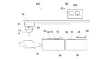
- FIG. 1 is a side view illustrating an example of a printing device 100 according to a first embodiment.
- 1 is a cross-sectional view showing an example of a printing pad 10 provided in a printing device 100 according to a first embodiment.
- 2 is a schematic diagram of a cross-sectional structure of the ink placement device 20 according to the first embodiment;
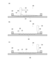
- FIG. 5 is a schematic diagram of a process for placing ink 40 on a printing base plate 50 using the ink placement device 20 of FIG. 4.
- 3 is a diagram showing an example of a detailed structure of the screen 21 according to the first embodiment.
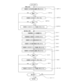
- 4 is a flow chart showing a method for producing a printed matter 70 by the printing device 100 according to the first embodiment. 4 is a flow of operations of the printing device 100 according to the first embodiment. 10 is a detailed flow diagram of an ink placement step (S1) according to the first embodiment. 10 is a modified example of the printing pad 10 used in the printing device 100 of the first embodiment. 2 is an enlarged schematic view of a printing surface 4 of the printing pad 10 according to the first embodiment.
- S1 ink placement step
- FIG. 1 is a schematic diagram of a case where a printing pad 10 is used to print on a printed object 70 according to the first embodiment.
- the printed object 70 is, for example, a car body, a door, a bonnet, etc.
- the car body is, for example, formed by plastically deforming metal and joining it by means such as welding, and the surface is painted after cleaning, surface treatment, plating, etc.
- the surface of the car body is formed by combining curved surfaces, and conventionally, painting is performed by spraying paint on the surface using means such as an air spray.
- an ink layer is formed on a car body using a printing pad 10 will be described. Note that the shape of the printed object 70 shown in FIG.
- the shape of the printed surface 70a can be changed as appropriate.
- the printed object 70 is not limited to a car body, etc., and can be changed as appropriate depending on the material and the surface treatment applied to the printed surface 70a to be printed.
- FIG. 2 is a side view showing an example of the printing device 100 according to the first embodiment.
- the printing device 100 includes a printing pad 10 that can be moved linearly in the vertical direction.
- the printing pad 10 is moved up and down by a vertical movement device 11 included in the printing device 100, and the printing surface 4 is pressed against the printing surface of the printed matter 70.
- the printing pad 10 is pressed against the printing surface 70a.
- the printing device 100 also includes a horizontal movement device 12.
- the horizontal movement device 12 moves the printing pad 10 and the vertical movement device 11 in the horizontal direction.
- the printing pad 10 is moved linearly up and down and pressed against the printing surface 70a, but it may be configured to move in the horizontal direction and be pressed against the printing surface 70a, for example.
- the printing pad 10 may also be moved and pressed using a robot arm or the like.
- the printing pad 10 is attached to a robot equipped with a multi-jointed arm instead of the vertical movement device 11 and the horizontal movement device 12, and the printing pad 10 is configured to move between the printing plate 50 and the printed matter 70.
- the printing pad 10 is moved by the horizontal movement device 12 above the printed matter 70, the cleaning device 60, the activation device 61, the air blow device 62, or the printing plate 50.
- the printing pad 10 is moved up and down by the vertical movement device 11, and the printing surface 4 is pressed against the printed matter 70, the cleaning device 60, the activation device 61, or the printing plate 50, respectively.
- the printing device 100 has, from the left side, an area where the printed matter 70 is placed, a surface treatment stage 86 equipped with a cleaning device 60, and a printing plate stage 85.
- the surface treatment stage 86 is equipped with an activation device 61 and an air blow device 62.
- the printing plate stage 85 is where the printing plate 50 is placed.
- these stages can be freely positioned, and the position can be changed as appropriate to suit the convenience of the operator and the location where the printing device 100 is installed.
- the cleaning device 60, activation device 61, and air blow device 62 of the printing device 100 may not be installed in the printing device 100.
- a stage and a jig for placing the printed matter 70 may be placed in the area where the printed matter 70 is placed.
- FIG. 3 is a cross-sectional view showing an example of the printing pad 10 provided in the printing device 100 according to the first embodiment.
- FIG. 3 shows a cross section passing through the top 6 of the printing pad 10 and perpendicular to the plane 13 to which the substrate 5 is fixed.
- the printing pad 10 shown in FIG. 3 is, for example, substantially hemispherical.
- the shape of the printing pad 10 is not limited thereto, and the shape can be appropriately changed according to the specifications of the printed matter 70, such as a bullet shape, a shape having a curved surface formed by rotating a parabola around its symmetrical axis, a shape of a part of an ellipsoid cut, a shape in which a bullet-shaped or semicircular cross section is continuously extended in a straight line, etc.
- the substrate 5 of the printing pad 10 includes an internal layer 1 and an external layer 2 covering the surface of the internal layer 1.
- the printing pad 10 is not limited to a two-layer structure, and may be a single-layer structure or may include more layers.
- the outer surface of the internal layer 1 has a shape in which the outer surface of the external layer 2 is offset inward, but is not limited thereto, and the outer surface of the internal layer 1 may be provided with unevenness.
- the printing pad 10 may have a cavity inside.
- the printing pad 10 has a peak 6 that is the first to come into contact with the printed matter 70 or the printing plate 50, and the peak 6 is configured as a dot or a line.
- the peak 6 is configured as a dot or a line.
- the substrate 5 is formed by molding, for example, silicone rubber.
- the substrate 5 has elasticity (flexibility) and is mixed with silicone oil to make it easily deformable.
- the substrate 5 has a substantially hemispherical shape, but the shape can be appropriately changed according to the specifications of the printed matter 70.
- the substrate 5 deforms when the printing pad 10 is pressed against the printing plate 50, the printing surface 4 adheres along the surface of the printing plate 50, and the ink 41 placed on the placement surface 51 of the printing plate 50 is transferred to the printing surface 4.
- the ink 41 placed on the placement surface 51 of the printing plate 50 is arranged in correspondence with the image to be printed on the printed matter 70, and forms a printing pattern according to the image.
- the material of the substrate 5 is not limited as long as the ink 41 can be transferred to the printing surface 70a when the printing pad 10 is pressed against the printing surface 70a.
- the substrate 5 may be formed from two materials with different hardnesses.
- the material of the outer layer 2 constituting the portion close to the printing surface 4 is set to a range of 10 to 20 points on the Asker C hardness scale.
- the material constituting the inner layer 1 inside the outer layer 2 is set to an Asker C hardness scale of 20 to 40 points.
- the inner layer 1 is located on the side where a force is applied to press the printing surface 4 against the surface to be printed during printing, and is located closer to the support member 7 than the outer layer 2.
- the support member 7 is connected to the vertical movement device 11 and is a part that transmits the force from the vertical movement device 11 to the printing pad 10.
- the hardness of the printing pad 10 In order for the printing pad 10 to deform and follow the surface to be printed 70a, it is desirable to set the hardness of the printing pad 10 low. Therefore, the hardness of the portion of the printing pad 10 on the printing surface 4 side that is pressed against the printed matter 70 is set lower than that of the inner layer 1. By configuring in this way, the overall shape of the printing pad 10 is easily maintained. At the same time, the outer layer 2, which is pressed directly against the surface to be printed, has the advantage of being easily deformed into the three-dimensional shape of the surface to be printed. However, the hardness of each part of the substrate 5 is not limited to the above hardness.
- a surface treatment stage 86 is disposed next to the printing stage 87 of the printing device 100.
- a cleaning device 60 is disposed on the surface treatment stage 86.
- the cleaning device 60 includes, for example, paper or adhesive tape. The printing surface 4 of the printing pad 10 is pressed against the surface of the paper or adhesive tape to remove ink 41, dirt, dust, and the like remaining after printing.
- the activation device 61 includes a storage tank for storing liquid and an absorption unit for absorbing and retaining the liquid.
- the printing surface 4 of the printing pad 10 is pressed against the surface of the absorption unit, so that the liquid retained by the absorption unit adheres to the printing surface 4.
- the printing pad 10 makes it easier to transfer the ink 41 placed on the printing plate 50 to the printing surface 4 by adhering or soaking the substrate 5 with water or a solvent.
- the liquid is appropriately selected according to the properties of the components contained in the ink 41, and has the property of softening the hard ink 41.
- the ink 41 is a mixture of synthetic resins such as acrylic resin or urethane resin, and water, thinner, xylene, or toluene, and it is preferable to select a liquid that has a high affinity with the materials contained in the ink 41 for use in the activation device 61.
- the liquid used in the activation device 61 is not limited to the above.
- the absorption unit of the activation device 61 is composed of, for example, a thin sheet-like absorbent material stacked on top of each other.
- the absorbent material is composed of, for example, paper, but is not limited to paper and may be composed of other materials such as cloth or resin as long as it absorbs liquid.
- the absorption unit may be composed of paper stacked on top of a sponge-like resin. The surface of the absorption unit against which the printing surface 4 of the printing pad 10 is pressed may dry out, become contaminated with ink 41 remaining on the printing surface 4 of the printing pad 10, or the surface of the absorption unit may be scraped, causing the paper constituting the absorption unit to tear.
- the paper located in the topmost layer of the absorption unit is peeled off and removed from the topmost layer of the absorption unit, and the upper layer can be removed one by one from the stack, or mechanically replaced.
- the method of replacing the paper located in the topmost layer is not limited to this method.
- the absorption unit is configured so that the top layer of paper and other materials can be removed or replaced as needed, and is configured to keep the surface clean. Since the liquid permeates the absorption unit, the printing surface 4 of the printing pad 10 can be pressed against it to activate the printing surface.
- the structure of the activation device 61 is not limited to the above, and other structures may also be used.
- Air blow device 62 adjusts the amount of water or solvent attached to the printing surface 4 of the printing pad 10 by the activation device 61 to an appropriate amount.
- the air blowing device 62 blows air toward the printing surface 4 to remove excess water or solvent from the printing surface 4. Note that the type and number of the air blowing devices 62 and the direction in which the air is blown are not limited.
- the printing plate stage 85 has the printing plate 50 placed on its upper surface, and includes an ink placement device 20 that places ink on the printing plate 50.
- the ink placement device 20 places ink 41 on the surface of the printing plate 50 using a screen 21.
- the printing plate stage 85 is configured so that the printing plate 50 is placed thereon, and the ink placement device 20 can be disposed above the printing plate 50 when the ink 41 is placed on the printing plate 50.
- the ink placement device 20 can be retracted from above the printing plate 50.
- the ink placement device 20 may be configured to be movable horizontally or vertically at least above the printing plate 50 by a feed device not shown.
- the printing plate 50 may be configured to be movable relative to the ink placement device 20.
- the ink placement device 20 or the printing plate 50 is configured to be movable to a position where it does not interfere with pressing the printing pad 10 against the printing plate 50.
- the printing plate 50 is placed on the printing plate stage 85, but for example, the surface of the printing plate stage 85 may be configured to function as the printing plate.
- the printing plate stage 85 may be configured to be freely movable relative to the printing device 100.
- the printing plate stage 85 may be equipped with a device for moving such as wheels, and the layout may be freely changed relative to each device constituting the printing device 100 as necessary.
- the printing plate stage 85 may be moved and placed next to each device other than the printing plate stage 85 constituting the printing device 100, and the printing plate stage 85 may be placed next to other printing devices 100 as necessary.
- the printing plate stage 85 may be provided with an ink placement device 20 and a printing plate 50, and the printing pad 10 may be pressed against the printing plate 50 by a robot arm or the like, or the printing plate stage 85 may be configured to supply the printing plate 50 on which the ink 40 is placed to the main body side of the printing device 100.
- the printing plate stage 85 is configured to be movable, which has the advantage that the ink placement device 20 and the printing plate 50 can be shared by multiple printing devices 100, and one ink placement device 20 can be used for multiple printing processes.
- the surface treatment stage 86 may also be configured to be movable, and each of the cleaning device 60, activation device 61, and air blow device 62 may also be configured to be movable.
- FIG. 4 is a schematic diagram of a cross-sectional structure of the ink placement device 20 according to the first embodiment.
- FIG. 5 is a schematic diagram of a process of placing the ink 40 on the printing plate 50 using the ink placement device 20 of FIG. 4.
- the ink placement device 20 is configured by fixing the screen 21 to a screen frame 22.
- the screen 21 is placed on the printing plate 50 by the ink 40 placed on the screen 21 passing through the opening 23.
- the ink 40 passes through the opening 23 by the squeegee 30 sliding on the surface of the screen 21, and is placed on the surface of the printing plate 50.
- the squeegee 30 is a spatula-shaped member, and slides with its tip pressed against the surface of the screen 21.
- the squeegee 30 is made of, for example, rubber or a resin material, and while moving so as to scrape off the ink 40 on the screen 21, it presses the screen 21 and the ink 40 against the printing plate 50 to place the ink 41 on the surface of the printing plate 50.
- ⁇ Screen 21> 6 is an example of a detailed structure of the screen 21 according to the first embodiment.
- the screen 21 is formed, for example, by coating an emulsion 25 on a mesh member 24 formed by weaving fibers in a mesh shape.
- the emulsion 25 partially covers the mesh structure of the screen 21 to form a portion of the screen 21 through which the ink 40 does not pass.
- the emulsion 25 is, for example, a liquid that hardens when irradiated with UV light.
- the screen 21 is created by applying the emulsion 25 to the mesh member 24, masking the mesh member 24 so that UV light is irradiated to areas other than the area where the openings 23 are to be provided, irradiating the entire screen 21 with UV light, and removing the unhardened emulsion 25.
- the mesh member 24 is formed with the openings 23 through which the ink 40 passes and the portion through which the ink 40 does not pass.
- the squeegee 30 slides on the surface of the screen 21, filling the openings 23 with the ink 40 placed on the screen 21.
- the squeegee 30 is loaded toward the screen 21 and slides on the screen 21, bringing the ink 41 filled in the openings 23 into contact with the printing plate 50. This transfers the ink 41 to the printing plate 50.
- the ink 41 is pressed against the printing plate 50 by the squeegee 30 as shown in FIG. 6(a)
- the screen 21 is separated from the printing plate 50 as shown in FIG. 6(b)
- the ink 41 remains on the printing plate 50.
- the thickness of the ink 41 placed on the placement surface of the printing plate 50 depends on the thickness h of the screen 21. For example, if the thickness h of the screen 21 is large, the ink 41 becomes thicker, and if the thickness h of the screen 21 is small, the ink 41 becomes thinner.
- the thickness h of the screen 21 is determined by the mesh member 24 formed by weaving fibers and the coated emulsion 25.
- the mesh member 24 is formed by weaving fibers vertically and horizontally, and therefore has a thickness including not only the fibers 24a appearing in the cross section shown in FIG. 6(a) but also the fibers 24b intersecting and woven with the fibers 24a.
- the thickness h of the screen 21 represents the thickness of the mesh member 24 in a state in which the emulsion 25 is coated on the screen 21.
- the thickness h of the screen 21 may be the thickness of the mesh member 24.
- the openings 23 may not be provided in some parts of the screen 21, and the entire screen 21 may be the openings 23.
- the mesh member 24 is formed by, for example, weaving resin fibers or metal fibers, and the gaps 24c between the weaved fibers 24a and 24b are gathered to form the openings 23.
- the mesh member 24 is configured so that, for example, the fibers 24a and 24b are arranged at equal intervals, and the intervals and the thicknesses of the fibers 24a and 24b are approximately equal.
- the mesh member 24 is not limited to being configured by weaving fibers, and may be configured by pressing fibers extending vertically and horizontally together.
- the mesh member 24 may also be configured of a metal plate and formed by providing multiple through holes in the metal plate. In addition, the mesh member 24 may be formed by using materials such as a resin plate or film instead of a metal plate.
- the multiple through holes may be processed into the portions that become the openings 23, for example, by laser processing.
- an emulsion may be applied to a metal plate provided with multiple through holes over the entire area of the metal plate, and the emulsion may be fixed to the portions other than the openings 23 to block some of the multiple through holes and form the openings 23.
- the emulsion may be something else as long as it can solidify to form the opening 23; for example, ink may be solidified, or an adhesive may be used.
- the thickness of the metal plate is the thickness h of the screen 21.
- the combined thickness of the thin metal plate and the emulsion 25 is the thickness h of the screen 21.
- the thickness h of the screen 21 may be the thickness of the mesh member 24.
- the ink 41 can be placed on the printing plate 50 so as to correspond to so-called solid printing (printing in which a predetermined printing area on the printing surface 70a of the printed matter 70 is filled with the ink 41 without any gaps).
- solid printing printing in which a predetermined printing area on the printing surface 70a of the printed matter 70 is filled with the ink 41 without any gaps.
- a relatively thick ink 41 can be placed on the printing plate 50 by the screen 21.
- the printing device 100 presses the printing pad 10 against the printing plate 50 to transfer the ink 41 to the printing surface 4, and presses the printing surface 4 to which the ink 41 has been transferred against the printing surface 70a having a curved or uneven surface, forming a layer of the ink 41 on the printing surface 70a.
- the printing device 100 according to the first embodiment can place a relatively thick ink 41 on the printing plate 50, so that the layer of the ink 41 formed on the printing surface 70a can also be made thick.
- the ink 41 can also be used for so-called solid printing due to the structure of the openings 23 of the screen 21.
- the printing device 100 can form a uniform ink layer (paint layer) on the surface of, for example, an automobile body, and compared to conventional paint whose viscosity has been reduced by a solvent such as thinner and applied by air spray, etc., the use of a highly viscous ink (paint) prevents splashing, etc. Therefore, a painting line using such a printing device 100 can eliminate or reduce processing equipment such as ventilation equipment and air purification equipment, and the amount of paint (ink) required for painting can be reduced.
- processing equipment such as ventilation equipment and air purification equipment
- the printing device 100 includes a control device 90.
- the control device 90 is formed of, for example, a microcomputer, and includes a calculation device 90a and a storage device 90b. The functions of the control device 90 are realized using the calculation device 90a and the storage device 90b (see Figure 2).
- the storage device 90b is a ROM that holds programs and data in advance, a RAM for temporarily storing data when a program is executed, etc.
- a non-volatile or volatile semiconductor memory such as a flash memory, an EPROM (Erasable and Programmable ROM), and an EEPROM (Electrically Erasable and Programmable ROM) is used.
- a removable recording medium such as a magnetic disk, a flexible disk, an optical disk, a CD (Compact Disc), an MD (Mini Disc), and a DVD (Digital Versatile Disc) may be used.
- the storage device 90b can store information obtained from the temperature sensor 68, etc., and information processed in the calculation device 90a.
- the storage device 90b stores programs for the OS (Operating System), various application programs, data stored in a database, etc., and these programs and data are processed by the CPU and work in cooperation with hardware resources to realize various functions.
- OS Operating System
- the arithmetic unit 90a performs various processes to execute the functions of the control unit 90.
- the arithmetic unit 90a compares, for example, room temperature information from a temperature sensor or the like with a temperature threshold value previously stored in the storage unit 90b to determine whether the room temperature is higher than the threshold value.
- the control unit 90 controls the output of the heater of the blower 66 to a predetermined value.
- the control unit 90 may also control the blower 66 to be operated for a shorter time, or may control the printing pad 10 to be stopped in front of the blower 66 and to be exposed to air for a limited time.
- control unit 90 may control the printing conditions to be changed according to the printed matter 70 targeted by the printing device 100. For example, when the printed surface 70a of the printed matter 70 has a complex shape with bumps and recesses, the control unit 90 may control the pressing speed of the printing pad 10 against the printed surface 70a to be slowed down. In addition, the control unit 90 may be configured to appropriately control the operation of each element of the printing device 100.
- the method for producing a printed matter first includes a printing plate preparation process OP1 in which a print image is formed on the placement surface 51 of the printing plate 50.
- ink is placed on the printing plate 50 using an ink placement device 20 as shown in FIG. 5.
- the printing plate 50 is, for example, in a flat plate shape and placed on a printing plate stage 85.
- the printing plate 50 is a thin flat plate made of an aluminum alloy, but a sheet material called a "grass receiving sheet" that has high retention and affinity with the ink 41 can also be used.
- the retention and affinity of the ink can be improved by providing the sheet material with irregularities.
- the surface of the printing plate 50 is finished to a predetermined surface roughness and is configured so that the ink 41 from the opening 23 of the screen 21 adheres to the printing plate 50.
- the material and structure are not limited.
- the sheet material may not have irregularities.
- the surface of the printing plate stage 85 may serve as the printing plate 50 without using a printing plate 50 such as a sheet material.
- the printing plate 50 may have a low affinity with the ink 41.
- solid printing is performed.
- a relatively large amount of ink 41 is placed on the printing plate 50, so when the ink 41 is transferred from the printing plate 50 to the printing pad 10, the ink 41 on the printing plate 50 may remain on the printing pad 10 without being transferred thereto.
- the printing plate 50 having a low affinity with the ink 41, there is an advantage that the transfer rate of the ink 41 to the printing pad 10 is improved.
- the printing plate 50 may be made of a film having a low affinity with the ink 41.
- the printing plate 50 may have a surface coated with a fluororesin or the like, or may have been processed to reduce the surface roughness. In other words, the printing plate 50 may be processed to reduce the affinity with the ink 41 depending on the material used for the ink 41. Furthermore, with the printing device 100 according to the first embodiment, when the ink 41 is placed on the printing plate 50 using the screen 21, the ink 41 is pushed out of the openings 23 by the pressure of the squeegee 30, so that the ink 41 is easily transferred to the printing plate 50 even if the affinity of the printing plate 50 with the ink 41 is low.
- the ink drying process OP2 After the printing plate creating process OP1 is completed, the ink drying process OP2 is performed. Immediately after the printing plate creating process OP1 is completed, the ink 41 on the printing plate 50 has a low viscosity. If the viscosity of the ink 41 on the printing plate 50 remains low, the ink 41 may be crushed and not transferred accurately when the printing pad 10 is pressed against the printing plate 50. In addition, the accuracy of the printed image may decrease due to bleeding of the ink 41, etc. Therefore, in the ink drying process OP2, the solvent contained in the ink 41 is evaporated to increase the viscosity of the ink 41. Note that if the viscosity of the ink 41 placed on the printing plate 50 by the ink placement device 20 is appropriate, the ink drying process OP2 can be omitted.
- the ink 41 on the printing plate 50 is heated by the heater 53, for example, to evaporate the solvent in the ink 41.
- the drying may be performed by other means such as blowing air, or the printing plate 50 may be left on the printing plate stage 85 and allowed to dry naturally for a predetermined time.
- the solvent contained in the ink 41 is more volatile than the other components in the ink 41. Therefore, the viscosity of the ink is increased by evaporating the solvent from the ink 41 by means such as blowing air, and increasing the proportion of components other than the solvent in the ink 41.
- the viscosity of the ink 41 is adjusted to, for example, 3 Pa ⁇ s to 1000 Pa ⁇ s. It is desirable to match the time required for drying the ink to the time required for the subsequent transfer process OP3 and pressing process OP4. By configuring in this way, a large number of printed matter 70 can be printed efficiently in succession.
- the printing plate 50 may be moved from the printing plate stage 85, or may remain placed on the printing plate stage 85. If the printing plate 50 is moved from the printing plate stage 85, another printing plate 50 can be immediately placed on the printing plate stage 85 and the printing plate creation process OP1 can be started, which has the advantage of shortening the cycle time of the entire offset printing process.
- a blower and a heater may be installed next to the ink placement device 20, and the air that has passed through the heater may be blown onto the printing plate 50 by the blower.
- the heater installed together with the blower is preferably set so that the temperature of the blown air is as high as possible but below the boiling point of the solvent contained in the ink 41.
- the solvent contained in the ink 41 is selected to be semi-dried in the ink drying process OP2.
- the solvent is selected to have a flash point of 40°C or higher and a boiling point of 120°C or higher.
- the heater temperature is set to, for example, 100°C. Note that a solvent with a high dissolving power may damage the ink placement device 20, so a solvent with a low dissolving power is desirable.
- the ink 41 used in the printing device 100 is not limited to the above.
- Transfer process OP3 In the transfer process OP3, when printing is performed using a printing pad 10 having a curved surface such as a parabolic shape, the printing pad 10 is pressed against the printing plate 50 from its apex, thereby transferring the printing image formed by the ink 41 on the printing plate 50.
- pressing process OP4 In the pressing step OP4, the printing pad 10 is pressed against the printed matter 70.
- the ink 41 adhering to the surface of the printing pad 10 is transferred to the surface of the printed matter 70.
- printing can be performed by following the shape of the surface.
- the printed matter 70 is positioned before the pressing step OP4 is performed. The positioning of the printed matter 70 may be performed using a jig or tool.
- the jig may be changed each time the pressing step is performed to change the posture of the printed matter 70, and the printing pad 10 may be adjusted so that it is pressed against the printed surface 70a at a desired position and angle.
- the angle at which the printing pad 10 is pressed against the printed surface 70a can be changed, so that the jig supporting the printed matter 70 does not need to be changed.
- the ink 41 transferred onto the surface of the printed matter 70 in the pressing step OP4 is fixed.
- the surface of the printed matter 70 may be irradiated with ultraviolet rays by an ultraviolet irradiation device (not shown) to harden the ink 41.
- an electron beam may be irradiated instead of ultraviolet rays.
- an ultraviolet irradiation device 80 that can irradiate ultraviolet rays along the curved surface.
- the method is not limited to curing the ink 41 by irradiating it with ultraviolet light or an electron beam, and may be, for example, a method of curing the ink 41 by heating it with a heater or drying it by blowing air. Alternatively, the ink 41 may be cured by natural drying.
- Fig. 8 is a flow chart showing the operation of the printing device 100 according to embodiment 1.
- the printing device 100 operates according to the flow shown in Fig. 8.
- the start process is a process performed immediately after starting the printing device 100.
- the surface of the printing pad 10 may not be activated immediately after starting the production of printed matter, so a process is performed to properly activate the printing surface 4 of the printing pad 10.
- the printing device 100 moves the printing pad 10 above the activation device 61 and lowers it toward the activation device 61.
- the printing pad 10 is raised after the printing surface 4 is pressed against the absorption unit of the activation device 61 and a predetermined range including the printing surface 4 comes into contact with the absorption unit. This is called the activation process (SP1).
- liquid such as water or solvent that has soaked into the absorption unit of the activation device 61 adheres to or soaks into the printing surface 4 of the printing pad 10.
- the printing pad 10 has an uneven surface, which makes it easier for the liquid that has soaked into the absorption unit to adhere to or soak into the printing pad 10. This process may be called the first start process.
- the printing device 100 After the first start step is completed, it is determined whether the amount of liquid adhering to the printing surface 4 of the printing pad 10 is appropriate (SP2). If the amount of liquid adhering to the printing surface 4 is not appropriate (NO in SP2), the printing device 100 performs the air blowing step (SP3). In the air blowing step, the air blowing device 62 blows air onto the printing surface 4 of the printing pad 10 to remove excess liquid adhering to the printing surface 4. Note that when the amount of liquid adhering to the printing surface 4 is not appropriate, this refers to when there is an excessive amount of liquid adhering to the printing surface 4. The above air blowing step is sometimes referred to as the second start step.
- the printing device 100 After completing the second start step, it is determined whether the amount of liquid adhering to the printing surface 4 of the printing pad 10 is appropriate (SP4). If excess water or solvent is still adhering to the printing surface 4 of the printing pad 10 (NO in SP4), the printing device 100 performs the absorption step (SP5). In the absorption step, the printing device 100 presses the printing surface 4 of the printing pad 10 against the cleaning device 60. This removes the excess liquid adhering to the printing surface 4 of the printing pad 10. The above cleaning step is sometimes referred to as the third start step.
- one or both of the air blowing step (SP3) and the absorbing step (SP5) may be omitted.
- the order of the air blowing step and the absorbing step may be changed.
- the air blowing step (SP3) and the absorbing step (SP5) of the starting step may be performed multiple times.
- the steps (SP2 and SP4) of determining whether the amount of liquid adhering to the printing surface 4 of the printing pad 10 is appropriate may be performed by a sensor or by an operator's visual inspection. If the operator makes the determination, he or she operates an operation panel (not shown) or the like to decide whether to proceed to the next step or to repeat the previous step.
- the repeat step includes an ink placement step (S1), an ink transfer step (S2), a drying step (S3), a pressing step (S4), a cleaning step (S5), an activation step (S6), an air blow step (S8), and an absorption step (S10).
- the printing device 100 advances the steps in the order of the ink placement step (S1), the ink transfer step (S2), the drying step (S3), the pressing step (S4), the cleaning step (S5), the activation step (S6), the air blow step (S8), and the absorption step (S10).
- the repeat step is not limited to this order.
- the printing device 100 performs the drying step (S3) to the absorption step (S9).
- the printing apparatus 100 may perform the next ink depositing step (S1) in parallel while the drying step (S3) through the absorbing step (S9) are being performed.
- the ink placement step (S1) corresponds to the printing plate creation step OP1 in the method for producing a printed matter shown in FIG. 7.
- the ink transfer step (S2) corresponds to the transfer step OP3 in the method for producing a printed matter shown in FIG. 7.
- a drying step (S3) may be performed in which air is blown onto the printing surface 4 of the printing pad 10 to increase the viscosity of the ink 41 on the printing surface 4.
- the drying step (S3) may or may not be performed depending on the viscosity of the ink 41 on the printing plate 50.
- the pressing step (S4) corresponds to the pressing step OP4 in the method for producing a printed matter shown in FIG. 7.
- a step of moving the printing pad 10 above the printed matter 70 is included between the ink transfer step (S2) and the pressing step (S4).
- the steps including the ink transfer step (S2), the step of moving the printing pad 10 above the printed matter 70, and the pressing step (S4) may be referred to as the printing step.
- one printing image area is completed each time the pressing step (S4) is performed.
- the repeating process may be performed multiple times while changing the position of the printing pad 10, and an ink layer may be formed over the entire top surface of the automobile by performing the pressing step (S4) multiple times.
- the cleaning step (S5) the printing surface 4 of the printing pad 10 after the ink 41 has been transferred to the printing surface is pressed against a flat cleaning surface of the cleaning device 60.
- the ink 41 remaining on the printing pad 10 is adhered to the cleaning surface.
- the cleaning surface is made of paper or adhesive tape, but is not limited to these.
- the activation step (S6) is the same as the activation step (SP1) in the start step.
- the air blow step (S8) is the same as the air blow step (SP3) in the start step.
- the absorption step (S10) is also the same as the absorption step (SP5) in the start step.
- the air blow step (S8) and the absorption step (S10) are performed according to the amount of liquid such as water or solvent adhering to the printing surface 4 of the printing pad 10, and one of them may be omitted, or at least one of them may be performed multiple times.
- the air blow step (S8) and the absorption step (S10) are performed according to the activation state of the printing surface 4 after checking the state of the printing surface 4 of the printing pad 10 before each step.
- the state of the printing surface 4 of the printing pad 10 is confirmed, and if the activation state of the printing surface 4 is appropriate, it is determined in the repeat judgment step (S11) whether or not to perform printing again. If printing is to be performed again (YES in S11), the ink depositing step (S1) and subsequent steps are repeated. If printing is not to be repeated (NO in S11), the production of the printed matter is terminated.
- the printing device 100 performs a start process when started up, and then repeats the process to print on a large number of printed materials 70. Note that if the printing pad 10 is in an activated state, the above start processes (SP1 to SP5) may be omitted.
- FIG. 9 is a detailed flow of the operation of the ink placement step (S1) according to the first embodiment.
- the ink placement step (S1) first involves a step of pouring ink 40 onto the screen 21 (A1).
- the ink 40 may be poured so that it is spread over the screen 21.
- the ink 40 may be placed on a portion of the screen 21.
- the ink 40 is arranged so that the ink 40 spreads over the openings 23 of the screen 21 in accordance with the movement of the squeegee 30, and the ink 40 can fill the openings 23.
- the squeegee 30 moves while sliding along the surface of the screen 21 (A2). As the squeegee 30 moves while sliding along the surface of the screen 21, it spreads the ink 40 over the screen 21, and at this time the ink 40 fills the openings 23. Note that the ink filling step (A2) can be omitted if the openings 23 are already filled with ink 40.
- the ink filling step (A2) is performed by the squeegee 30, but may also be performed using a dedicated filling squeegee.
- the screen 21 with the ink 40 poured in is placed above the printing plate 50 (A3).
- the screen 21 and the printing plate 50 are placed with a gap of, for example, about 1 mm between them.
- the screen 21 is placed at a predetermined position relative to the printing plate 50.
- the screen 21 may be positioned by abutting the screen frame 22 against a jig or the like, or may be positioned by a mechanism that allows the screen 21 or the printing plate 50 to move to predetermined positions relative to each other. In the process of placing the screen 21 above the printing plate 50, the screen 21 or the printing plate 50 is moved.
- the printing plate 50 is configured to move alternately between a position when the ink placement step (S1) is performed and a position when the transfer step (S2) is performed.
- the printing plate 50 may be moved by a slide mechanism or the like so that the printing plate 50 is at a fixed position in the ink placement step (S1) and the transfer step (S2), respectively.
- the screen 21 may be moved by a slide mechanism or the like. For example, when the printing plate 50 is fixed and when the surface of the printing plate stage 85 is used as the printing plate 50, the screen 21 is moved.
- the squeegee 30 moves while sliding along the surface of the screen 21, and the screen 21 is pressed against the printing plate 50, thereby transferring the ink 40 filled in the openings 23 to the printing plate 50 (A4).
- the squeegee 30 slides along the surface of the screen 21 while being subjected to a predetermined load toward the screen 21.
- the screen 21 is pressed against the printing plate 50 by the squeegee 30.
- the portions of the screen 21 against which the squeegee 30 is pressed are in close contact with the surface of the printing plate 50.
- the ink 41 filled in the openings 23 comes into contact with the surface of the printing plate 50 as it is pressed against the printing plate 50 together with the screen 21 by the squeegee 30, and adheres to the surface of the printing plate 50.
- one squeegee 30 is used to fill the openings 23 with ink 40 (A2) and transfer the ink from the screen 21 to the printing plate 50 (A4), but the squeegee 30 may be made up of two squeegees: one for filling and one for transferring.
- the screen 21 is separated from the printing plate 50 (A5).
- This step may be achieved by moving the screen 21 or the printing plate 50.
- the printing plate 50 is moved to a position where the transfer step (S2) is performed, thereby separating the screen 21 and the printing plate 50.
- the process (A1) of pouring ink 40 onto the screen 21 may be omitted. In other words, if there is sufficient ink 40 remaining on the screen 21 from the previous time, that ink 40 can be used to place ink 41 on the printing plate 50.
- the process (A3) of positioning the screen 21 above the printing plate 50 may be performed before pouring ink (A1) or filling the openings 23 with ink (A2).
- FIG. 10 is a modified example of the printing pad 10 used in the printing device 100 of the first embodiment.
- the printing pad 10 according to the first embodiment may be provided with a protective coating layer 3 covering the surface of the substrate 5.
- the protective coating layer 3 constitutes the outer printing surface 4 of the printing pad 10.
- the protective coating layer 3 is formed by, for example, attaching a 0.5 mm silicone rubber sheet to the surface of the outer layer 2.
- the protective coating layer 3 also has the effect of preventing the silicone oil contained in the soft silicone rubber inside from seeping out onto the printing surface 4.
- the outer surface of the protective coating layer 3 constitutes the printing surface 4 and is repeatedly pressed against the printing plate 50 and the surface to be printed, so it is necessary to have durability against scratches and wear. Therefore, the protective coating layer 3 uses a material that is harder than the outer layer 2, and is thin so that the printing surface 4 follows the surface to be printed when pressed against the surface to be printed.
- the thickness of the protective coating layer 3 is as thin as possible, for example, in the range of 0.1 mm to 1 mm.
- the material of the protective coating layer 3 is not limited to silicone rubber, and any material can be selected as long as it follows the deformation of the inner layer 1 and the outer layer 2.
- the printing pad 10 may be further formed into a multi-layer structure.
- the inner layer 1 or the outer layer 2 of the printing pad 10 shown in FIG. 10 may be further formed into a multi-layer structure using materials with different hardnesses.
- the protective coating layer 3 is attached to the surface of the substrate 5 (the surface of the outer layer 2), but if it is damaged by scratches or wear, it can be peeled off from the surface of the substrate 5 and replaced with a new one.
- the protective coating layer 3 is less expensive than the substrate 5, and the substrate 5 inside can be used as is by replacing it. Therefore, by updating the protective coating layer 3, the expensive substrate 5 can be used repeatedly, and the state of the printing surface 4 of the printing pad 10 can be kept suitable for printing.
- the printing device 100 according to the first embodiment can reduce the cost of printing.
- the outer layer 2 constituting the substrate 5 is softer than the inner layer 1. Therefore, it can follow the shape of the printed matter 70 well.
- the surface may harden by repeatedly updating (replacing) the protective coating layer 3 described above.
- the outer layer 2 can also be replaced.
- the inner layer 1 can be used for a long period of time.
- the substrate 5 is composed of the inner layer 1 and the outer layer 2, but it may be composed of only one layer of the inner layer 1.
- the protective coating layer 3 may be provided on the substrate 5 formed of only one layer of the inner layer 1.
- the substrate 5 when the protective coating layer 3 attached to the substrate 5 is peeled off to replace it, the substrate 5 may be damaged, deep scratches may be made from the printing surface 4 of the printing pad 10, or the surface of the substrate 5 may become hard or otherwise deteriorate. For this reason, it is preferable that the substrate 5 is composed of multiple layers as shown in FIG. 3 and FIG. 10.
- the printing surface 4 which is the surface of the printing pad 10 and is pressed against the printing plate 50, may preferably have minute irregularities formed on the surface according to the thickness of the ink 41 to be printed.
- the ink 41 placed on the printing plate 50 can be made thick by placing the ink 41 on the printing plate 50 using the screen 21. By forming irregularities on the printing surface 4 according to the thickness of the ink 41 on the printing plate 50, the ink 41 transferred to the printing pad 10 can also be made thicker than before.
- the surface of the printing pad 10 is uneven.
- the uneven shape is formed, for example, by transferring the uneven shape of the mold surface when molding the printing pad 10.
- the uneven shape may be formed on the surface when molding the protective coating layer 3 to be attached to the surface of the substrate 5.
- the uneven shape is applied to the protective coating layer 3, which is a sheet-like member, so the desired uneven shape can be easily obtained.
- the protective coating layer 3 which is a sheet-like member, so the desired uneven shape can be easily obtained.
- the substrate 5 is large, if the height difference can be adjusted by changing only the protective coating layer 3 on the surface, it is advantageous in terms of cost and production time.
- the height difference between the highest and lowest parts of the uneven shape of the surface of the protective coating layer 3 after molding is formed to a desired value, it may be attached to the substrate 5 as it is.
- the surface of the sheet constituting the protective coating layer 3 may be rubbed with an abrasive such as an abrasive cloth paper to remove the protruding parts 4a (see FIG. 11) of the uneven shape, that is, the high parts.
- an abrasive sponge such as a melamine sponge may be used.
- the surface of the sheet forming the protective coating layer 3 may be formed in a rough state, and then the surface may be polished or otherwise processed to adjust the condition so that it is easily transferred to the printing surface 4.
- the above description is for the case of a printing pad 10 having a protective coating layer 3, but in the case of a printing pad 10 not having a protective coating layer 3 as shown in FIG. 3, the surface of the substrate 5 may be formed roughly in advance, and the uneven shape of the surface may be gradually adjusted by polishing or the like.
- the height difference between the highest and lowest points of the uneven shape 14 is set according to the thickness of the ink 41 placed on the printing plate 50. Because the thickness of the ink 41 placed on the printing plate 50 is adjusted according to the thickness h of the screen 21 shown in FIG. 6, the height difference d of the uneven shape 14 on the printing surface 4 of the printing pad 10 is set according to the thickness h of the screen 21.
- the thickness of the paint layer formed by one coat of paint is 10 ⁇ m to 20 ⁇ m.
- the thickness of the ink 41 placed on the placement surface of the printing plate 50 in the ink placement step (S1) should be set to 10 ⁇ m to 20 ⁇ m. Therefore, the height difference from the highest to lowest part of the uneven shape 14 on the printing surface 4 of the printing pad 10 should also be set to 10 ⁇ m to 20 ⁇ m.
- it is difficult to form an ink layer of 10 ⁇ m to 20 ⁇ m on the printed surface 70a in one print it is recommended to print in multiple coats.
- the thickness of the ink layer on the printing plate 50 (the thickness of the ink 41 in Figures 5 and 6) is approximately the same as the thickness of the screen 21.
- the value of the height difference from the highest to the lowest part of the uneven shape of the printing surface 4 is set to be minutely smaller than the thickness h of the screen 21 to make it easier to transfer the ink.
- the thickness h of the screen 21 is set to be larger than the height difference of the uneven shape of the printing surface 4 of the printing pad 10.
- the height difference from the highest to the lowest part of the uneven shape of the printing surface 4 may be expressed as a maximum height roughness Rz or a three-dimensional surface roughness SZ .
- the surface roughness Rz and SZ of the printing surface 4 are measured with a non-contact type roughness meter.
- the height difference from the highest to the lowest part of the uneven shape may be set based on the surface roughness RZ and SZ measured with the non-contact type roughness meter.
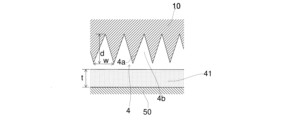
- FIG. 11 is an enlarged schematic diagram of the printing surface 4 of the printing pad 10 according to the first embodiment.
- the uneven shape formed on the printing surface 4 is crushed when the printing surface 4 is pressed against the printing plate 50, and is deformed in a direction in which the height difference d is reduced. Therefore, the uneven shape is preferably set so that the height difference d, which is the dimension from the apex of the protrusion 4a to the valley 4b, is larger than the width between the apexes of the protrusion 4a.
- FIG. 11 shows a substantially uniform uneven shape on the printing surface 4, in reality, the positions of the apexes of the protrusions 4a and the bottoms of the valleys 4b vary.
- the ink viscosity can be set low, for example to 10 Pa ⁇ s (100 poise) or less, to make it smooth.
- the ink viscosity is not limited to the above.
- the present invention has been described above based on the embodiments, but the present invention is not limited to the configurations of the above-mentioned embodiments.
- the combination of components is not limited to the combinations in the embodiments, but can be modified as appropriate.
- we would like to emphasize that the gist (technical scope) of the present invention also includes the scope of various modifications, applications, and uses that a person skilled in the art may make as necessary.
- Ink 50 Printing plate, 51 placement surface, 53 heater, 60 cleaning device, 61 activation device, 62 air blow device, 66 blower, 68 temperature sensor, 70 printed matter, 70a printed surface, 74 periphery, 75 connection area, 75a connection area, 75b connection area, 80 ultraviolet irradiation device, 85 printing plate stage, 86 surface treatment stage, 87 printing stage, 90 control device, 90a calculation device, 90b storage device, 100 printing device, height difference d, h thickness, spacing w.
Landscapes
- Engineering & Computer Science (AREA)
- Mechanical Engineering (AREA)
- Printing Methods (AREA)
Priority Applications (4)
| Application Number | Priority Date | Filing Date | Title |
|---|---|---|---|
| KR1020247034774A KR20250065265A (ko) | 2023-11-02 | 2023-11-02 | 인쇄 장치 및 인쇄물의 제조 방법 |
| PCT/JP2023/039575 WO2025094347A1 (ja) | 2023-11-02 | 2023-11-02 | 印刷装置及び印刷物の製造方法 |
| JP2025508922A JPWO2025094347A1 (https=) | 2023-11-02 | 2023-11-02 | |
| CN202380037437.XA CN120265463A (zh) | 2023-11-02 | 2023-11-02 | 印刷装置及印刷物的制造方法 |
Applications Claiming Priority (1)
| Application Number | Priority Date | Filing Date | Title |
|---|---|---|---|
| PCT/JP2023/039575 WO2025094347A1 (ja) | 2023-11-02 | 2023-11-02 | 印刷装置及び印刷物の製造方法 |
Publications (1)
| Publication Number | Publication Date |
|---|---|
| WO2025094347A1 true WO2025094347A1 (ja) | 2025-05-08 |
Family
ID=95582586
Family Applications (1)
| Application Number | Title | Priority Date | Filing Date |
|---|---|---|---|
| PCT/JP2023/039575 Pending WO2025094347A1 (ja) | 2023-11-02 | 2023-11-02 | 印刷装置及び印刷物の製造方法 |
Country Status (4)
| Country | Link |
|---|---|
| JP (1) | JPWO2025094347A1 (https=) |
| KR (1) | KR20250065265A (https=) |
| CN (1) | CN120265463A (https=) |
| WO (1) | WO2025094347A1 (https=) |
Citations (8)
| Publication number | Priority date | Publication date | Assignee | Title |
|---|---|---|---|---|
| JPH08183165A (ja) * | 1994-12-28 | 1996-07-16 | Sony Corp | パッド印刷に使用されるパッド |
| JP2000094638A (ja) * | 1998-09-21 | 2000-04-04 | Fujitsu Takamisawa Component Ltd | パッド転写式印刷法、キートップ及びその標示印刷方法 |
| JP2007148381A (ja) * | 2005-10-24 | 2007-06-14 | Bridgestone Corp | 情報表示用パネルの製造方法 |
| KR100881232B1 (ko) * | 2007-05-03 | 2009-02-05 | 한국기계연구원 | 패드 프린팅 방법 및 그 장치 |
| JP2014200935A (ja) * | 2013-04-02 | 2014-10-27 | パナソニック株式会社 | スクリーン印刷機及びスクリーン印刷方法 |
| JP7091385B2 (ja) | 2020-03-30 | 2022-06-27 | ダイハツ工業株式会社 | 塗装方法 |
| JP7297141B2 (ja) | 2020-02-19 | 2023-06-23 | 株式会社秀峰 | 印刷装置、及び印刷物の製造方法 |
| JP7325599B2 (ja) * | 2020-02-19 | 2023-08-14 | 株式会社秀峰 | 印刷装置、及び印刷物の製造方法 |
-
2023
- 2023-11-02 JP JP2025508922A patent/JPWO2025094347A1/ja active Pending
- 2023-11-02 WO PCT/JP2023/039575 patent/WO2025094347A1/ja active Pending
- 2023-11-02 KR KR1020247034774A patent/KR20250065265A/ko active Pending
- 2023-11-02 CN CN202380037437.XA patent/CN120265463A/zh active Pending
Patent Citations (8)
| Publication number | Priority date | Publication date | Assignee | Title |
|---|---|---|---|---|
| JPH08183165A (ja) * | 1994-12-28 | 1996-07-16 | Sony Corp | パッド印刷に使用されるパッド |
| JP2000094638A (ja) * | 1998-09-21 | 2000-04-04 | Fujitsu Takamisawa Component Ltd | パッド転写式印刷法、キートップ及びその標示印刷方法 |
| JP2007148381A (ja) * | 2005-10-24 | 2007-06-14 | Bridgestone Corp | 情報表示用パネルの製造方法 |
| KR100881232B1 (ko) * | 2007-05-03 | 2009-02-05 | 한국기계연구원 | 패드 프린팅 방법 및 그 장치 |
| JP2014200935A (ja) * | 2013-04-02 | 2014-10-27 | パナソニック株式会社 | スクリーン印刷機及びスクリーン印刷方法 |
| JP7297141B2 (ja) | 2020-02-19 | 2023-06-23 | 株式会社秀峰 | 印刷装置、及び印刷物の製造方法 |
| JP7325599B2 (ja) * | 2020-02-19 | 2023-08-14 | 株式会社秀峰 | 印刷装置、及び印刷物の製造方法 |
| JP7091385B2 (ja) | 2020-03-30 | 2022-06-27 | ダイハツ工業株式会社 | 塗装方法 |
Also Published As
| Publication number | Publication date |
|---|---|
| CN120265463A (zh) | 2025-07-04 |
| JPWO2025094347A1 (https=) | 2025-05-08 |
| KR20250065265A (ko) | 2025-05-12 |
Similar Documents
| Publication | Publication Date | Title |
|---|---|---|
| JP6783252B2 (ja) | コーティング装置 | |
| JP3300253B2 (ja) | 自動車の新塗装部における損傷個所を経済的に修理する方法 | |
| CN101443703A (zh) | 用于使压制板或连续带形成表面结构的方法 | |
| JP2006503731A (ja) | 金属の装飾処理の方法 | |
| JP2000516529A (ja) | 基体表面にフォトレジストを塗布するための装置および方法 | |
| WO2025094347A1 (ja) | 印刷装置及び印刷物の製造方法 | |
| JP7325599B2 (ja) | 印刷装置、及び印刷物の製造方法 | |
| JP7297141B2 (ja) | 印刷装置、及び印刷物の製造方法 | |
| JP3022298B2 (ja) | 印刷ステンシルを作製する方法とその装置 | |
| KR101682566B1 (ko) | 옵셋 인쇄장치 실린더 자켓용 금속판의 표면처리방법 | |
| JP2003241397A (ja) | 印刷用シームレススリーブ体の製造方法および装置 | |
| JPWO2021140492A5 (https=) | ||
| WO2024166146A1 (ja) | 印刷物、印刷物の製造方法、及び照明装置 | |
| JP3606532B2 (ja) | 化粧板の製造方法 | |
| JP7797051B2 (ja) | 印刷装置、及び印刷物の製造方法 | |
| JP3133402B2 (ja) | 研磨テープ及びその製造方法 | |
| JPS6354289A (ja) | プリンテイングスクリ−ンおよびその製造方法 | |
| KR20170085677A (ko) | 도포면 처리와 프린팅 도포 방식을 이용한 목재판 엣지면의 표면처리 방법 | |
| HK40114162A (zh) | 印刷物及印刷物的制造方法 | |
| KR20130115766A (ko) | 판재 표면 상에 롤러를 이용한 무늬의 도장공법 및 이에 의해 무늬가 도장된 판재 | |
| EP4711145A1 (en) | Printed material, and method for producing printed material | |
| JPS6057391B2 (ja) | 凹凸模様化粧板の製造方法 | |
| JP7651915B2 (ja) | 塗装方法 | |
| JP2004175578A (ja) | 透明保護層を有する窯業系基材の塗装方法とその化粧基材 | |
| CN109249717A (zh) | 发泡印刷方法 |
Legal Events
| Date | Code | Title | Description |
|---|---|---|---|
| WWE | Wipo information: entry into national phase |
Ref document number: 18858548 Country of ref document: US |
|
| WWE | Wipo information: entry into national phase |
Ref document number: 202380037437.X Country of ref document: CN |
|
| WWE | Wipo information: entry into national phase |
Ref document number: 202447091727 Country of ref document: IN |
|
| ENP | Entry into the national phase |
Ref document number: 2025508922 Country of ref document: JP Kind code of ref document: A |
|
| WWE | Wipo information: entry into national phase |
Ref document number: 2025508922 Country of ref document: JP |
|
| WWP | Wipo information: published in national office |
Ref document number: 202447091727 Country of ref document: IN |
|
| 121 | Ep: the epo has been informed by wipo that ep was designated in this application |
Ref document number: 23933284 Country of ref document: EP Kind code of ref document: A1 |
|
| WWP | Wipo information: published in national office |
Ref document number: 202380037437.X Country of ref document: CN |