WO2025088747A1 - 内燃機関の排気還流装置のフェールセーフ方法および装置 - Google Patents
内燃機関の排気還流装置のフェールセーフ方法および装置 Download PDFInfo
- Publication number
- WO2025088747A1 WO2025088747A1 PCT/JP2023/038623 JP2023038623W WO2025088747A1 WO 2025088747 A1 WO2025088747 A1 WO 2025088747A1 JP 2023038623 W JP2023038623 W JP 2023038623W WO 2025088747 A1 WO2025088747 A1 WO 2025088747A1
- Authority
- WO
- WIPO (PCT)
- Prior art keywords
- exhaust gas
- gas recirculation
- combustion engine
- internal combustion
- diagnosis
- Prior art date
- Legal status (The legal status is an assumption and is not a legal conclusion. Google has not performed a legal analysis and makes no representation as to the accuracy of the status listed.)
- Pending
Links
Images





Classifications
-
- F—MECHANICAL ENGINEERING; LIGHTING; HEATING; WEAPONS; BLASTING
- F02—COMBUSTION ENGINES; HOT-GAS OR COMBUSTION-PRODUCT ENGINE PLANTS
- F02D—CONTROLLING COMBUSTION ENGINES
- F02D21/00—Controlling engines characterised by their being supplied with non-airborne oxygen or other non-fuel gas
- F02D21/06—Controlling engines characterised by their being supplied with non-airborne oxygen or other non-fuel gas peculiar to engines having other non-fuel gas added to combustion air
- F02D21/08—Controlling engines characterised by their being supplied with non-airborne oxygen or other non-fuel gas peculiar to engines having other non-fuel gas added to combustion air the other gas being the exhaust gas of engine
-
- F—MECHANICAL ENGINEERING; LIGHTING; HEATING; WEAPONS; BLASTING
- F02—COMBUSTION ENGINES; HOT-GAS OR COMBUSTION-PRODUCT ENGINE PLANTS
- F02D—CONTROLLING COMBUSTION ENGINES
- F02D41/00—Electrical control of supply of combustible mixture or its constituents
- F02D41/22—Safety or indicating devices for abnormal conditions
-
- F—MECHANICAL ENGINEERING; LIGHTING; HEATING; WEAPONS; BLASTING
- F02—COMBUSTION ENGINES; HOT-GAS OR COMBUSTION-PRODUCT ENGINE PLANTS
- F02M—SUPPLYING COMBUSTION ENGINES IN GENERAL WITH COMBUSTIBLE MIXTURES OR CONSTITUENTS THEREOF
- F02M26/00—Engine-pertinent apparatus for adding exhaust gases to combustion-air, main fuel or fuel-air mixture, e.g. by exhaust gas recirculation [EGR] systems
- F02M26/49—Detecting, diagnosing or indicating an abnormal function of the EGR system
Definitions
- This invention relates to an exhaust gas recirculation device for an internal combustion engine that recirculates exhaust gas from the exhaust system of the internal combustion engine to the intake system via an exhaust gas recirculation control valve, and in particular to fail-safe technology for when an abnormality occurs in the exhaust gas recirculation device.
- Patent Document 1 discloses that when a self-diagnosis function determines that the valve opening control system of the exhaust gas recirculation device has failed, the exhaust gas recirculation control valve is fully closed.
- Patent document 2 also discloses that when the exhaust gas recirculation control valve is diagnosed as having an open circuit failure, the engine output is limited to a small value.
- a fail-safe method for an exhaust gas recirculation device of an internal combustion engine comprises: In an exhaust gas recirculation device for an internal combustion engine, exhaust gas is recirculated from an exhaust system of the internal combustion engine to an intake system via an exhaust gas recirculation control valve, As a primary diagnosis, a diagnosis is made as to whether the exhaust gas recirculation control valve is operating in accordance with a command. When an abnormality is diagnosed in this primary diagnosis, the exhaust gas recirculation control valve is fully closed, As a secondary diagnosis, an actual opening of the exhaust gas recirculation control valve is detected, and a diagnosis is made as to whether or not the actual opening is in a fully closed position. If the actual opening is not the fully closed position, the output of the internal combustion engine is limited.
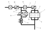
- FIG. 1 is an explanatory diagram showing a configuration of an exhaust gas recirculation device for an internal combustion engine according to an embodiment
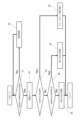
- 4 is a flowchart showing a process flow of fail-safe control according to an embodiment.
- FIG. 2 is a functional block diagram showing a main part of an engine controller.
- FIG. 4 is a characteristic diagram showing an example of output limiting.
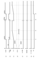
- 5 is a time chart showing an example of the operation of the primary diagnosis and the secondary diagnosis.
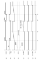
- 11 is a time chart showing another operation example. 10 is a time chart showing yet another operation example.
- FIG. 4 is an explanatory diagram showing another example of the configuration of the exhaust gas recirculation device.
- FIG. 11 is an explanatory diagram showing yet another example of the configuration of the exhaust gas recirculation device.
- FIG. 1 is an explanatory diagram showing a schematic configuration of an exhaust gas recirculation system according to one embodiment.
- the internal combustion engine 1 according to one embodiment is a spark ignition internal combustion engine, a so-called gasoline engine, to which an intake passage 3 is connected via an intake manifold 2, and an exhaust passage 5 is connected via an exhaust manifold 4.
- the intake passage 3 is provided with an electronically controlled throttle valve 7 whose opening is controlled by a control signal from the engine controller 6, and further upstream is an air flow meter 8, such as a hot wire air flow meter 8, which measures the amount of intake air.
- an electronically controlled throttle valve 7 whose opening is controlled by a control signal from the engine controller 6, and further upstream is an air flow meter 8, such as a hot wire air flow meter 8, which measures the amount of intake air.
- the exhaust gas recirculation passage 10 that constitutes the exhaust gas recirculation system has one end connected to the exhaust passage 5 and the other end connected to the intake passage 3 downstream of the throttle valve 7. A part of the exhaust gas is recirculated from the exhaust system to the intake system as EGR gas via this exhaust gas recirculation passage 10.
- the exhaust gas recirculation passage 10 is provided with an exhaust gas recirculation control valve 11 (hereinafter also referred to as an EGR valve) that variably controls the exhaust gas recirculation amount and therefore the exhaust gas recirculation rate (EGR rate).
- An EGR gas cooler 12 that cools the EGR gas, for example by heat exchange with cooling water, is provided upstream of the EGR valve 11 (i.e., on the exhaust passage 5 side).
- the EGR valve 11 is configured to open and close a butterfly valve-type valve body using a motor.
- the spring force of a return spring acts on the valve body in the closing direction, and when the motor is not energized, the EGR valve 11 is fully closed due to the action of the return spring.
- the opening of the EGR valve 11, i.e., the rotation angle of the butterfly valve-type valve body, is detected by a position sensor 13 (hereinafter abbreviated as POS sensor) built into the EGR valve 11.
- POS sensor 13 position sensor 13
- the rotation of the motor is controlled by the engine controller 6 via a drive circuit (not shown) so that the opening detected by this POS sensor 13 becomes the target opening.
- the engine controller 6 receives detection signals from numerous sensors, such as a crank angle sensor 15 for detecting engine speed, an accelerator pedal opening sensor 16 for detecting the amount of depression of the accelerator pedal operated by the driver, an air-fuel ratio sensor 17 provided in the exhaust passage 5, a cooling water temperature sensor 18, an intake air temperature sensor 19, and a knocking sensor 20. Based on these detection signals, the engine controller 6 executes output control, air-fuel ratio control, ignition timing control, and the like for the internal combustion engine 1.
- sensors such as a crank angle sensor 15 for detecting engine speed, an accelerator pedal opening sensor 16 for detecting the amount of depression of the accelerator pedal operated by the driver, an air-fuel ratio sensor 17 provided in the exhaust passage 5, a cooling water temperature sensor 18, an intake air temperature sensor 19, and a knocking sensor 20.
- the engine controller 6 controls the opening of the EGR valve 11 so as to achieve a target EGR rate determined from the load and rotation speed of the internal combustion engine 1.
- the engine controller 6 also achieves a self-diagnosis function and a fail-safe function for the exhaust gas recirculation device, as described below.
- FIG. 2 is a flowchart showing the process flow for the self-diagnosis function and fail-safe function of the exhaust gas recirculation device executed by the engine controller 6. The routine shown in this flowchart is executed repeatedly while the internal combustion engine 1 is operating.
- the first step 1 it is determined whether the difference (absolute value) ⁇ EGRV between the target opening tEGRV of the EGR valve 11 calculated by the engine controller 6 and the actual opening rEGRV detected by the POS sensor 13 is equal to or greater than a predetermined set value # ⁇ EGRV. More specifically, it is determined whether the state in which the difference ⁇ EGRV is equal to or greater than the set value # ⁇ EGRV continues for a predetermined period (predetermined time or number of cycles) or more. If the result is NO here, the process proceeds to step 2, and normal control is continued.
- the set value # ⁇ EGRV is set as a value greater than the normal difference due to a delay that may occur during the opening control of the EGR valve 11.
- step 1 corresponds to a primary diagnosis of whether the EGR valve 11 is operating in accordance with the command.
- the condition of "continuing for a specified period of time" is intended to eliminate misdiagnosis due to momentary abnormal values during a transition, and therefore the period is set to be relatively short.
- step 1 determines whether the primary diagnosis diagnoses an abnormality. If the determination in step 1 is YES, that is, if the primary diagnosis diagnoses an abnormality, the process proceeds from step 1 to step 3, and the power supply to the EGR valve 11 is cut off.
- the EGR valve 11 is equipped with a return spring, turning off the power supply to the EGR valve 11 corresponds to the process of fully closing the EGR valve 11 when the primary diagnosis indicates an abnormality.
- step 4 If the determination in step 4 is YES, proceed to step 5 and do not perform fail-safe operation including output restriction, which will be described later.
- the EGR valve 11 since the EGR valve 11 is actually fully closed, there is no concern about combustion instability due to excessive exhaust gas recirculation, and therefore normal operation is permitted even if the primary diagnosis indicates that there is some abnormality in the exhaust gas recirculation system.
- step 4 If the determination in step 4 is NO, this means that the EGR valve 11 is not actually fully closed even though it should be. Therefore, the output of the internal combustion engine 1 is restricted to avoid stalling due to excessive exhaust gas recirculation.
- the output restriction is provided in two stages with different levels, and one of the output restrictions is selected depending on the actual opening degree rEGRV of the EGR valve 11.
- step 4 determines whether the actual opening rEGRV detected by the POS sensor 13 is equal to or less than a predetermined second threshold #EGRV2.
- the second threshold #EGRV2 is set to an appropriate opening greater than the first threshold #EGRV1. If the determination in step 6 is YES, the process proceeds to step 7, where the first output restriction with a relatively small degree of restriction is executed. If the determination in step 6 is NO, the process proceeds to step 8, where the second output restriction with a relatively large degree of restriction is executed.
- a fault diagnosis to determine whether there is an abnormality in the POS sensor 13 is performed by another routine not shown, and the secondary diagnosis (step 4) using the detection value (rEGRV) of the POS sensor 13 is performed on the condition that there is no abnormality in the POS sensor 13.
- the secondary diagnosis is not performed in response to the abnormality diagnosed in the primary diagnosis, and no output restriction is imposed on the internal combustion engine 1.
- the process proceeds to step 5. This is in consideration of the low reliability of the primary diagnosis due to an abnormality in the POS sensor 13, and is intended to avoid a decrease in driving performance due to a misdiagnosis.
- the secondary diagnosis is not performed in response to the abnormality diagnosis in the primary diagnosis, and the output of the internal combustion engine 1 is uniformly limited (for example, the second output limit or the first output limit).
- the process proceeds to step 8 or step 7. This prioritizes reliably avoiding a stall, even if this results in a decrease in driving performance.
- FIG. 4 is a characteristic diagram showing an example of the characteristics of the first output limit and the second output limit with the torque and rotation speed of the internal combustion engine 1 as parameters.
- the line WOT in the diagram shows the full-throttle characteristics when no output limit is applied.
- the line LIM1 shows the characteristics of the first output limit
- the line LIM2 shows the characteristics of the second output limit.
- the output limit is realized, for example, by limiting the opening of the throttle valve 7.
- the second output limit (LIM2) the output is significantly limited to avoid stalling, but under the first output limit (LIM1), a relatively large output is obtained, making normal driving possible, for example.
- FIG. 3 is a functional block diagram showing the functions of the main parts of the engine controller 6 related to the above-mentioned diagnosis and fail-safe.
- the engine controller 6 is equipped with a primary diagnosis unit 21, a secondary diagnosis unit 22, a POS sensor diagnosis unit 23, an EGR valve drive permission command unit 24, and a fail-safe command unit 25.
- the primary diagnosis unit 21 receives the target opening tEGRV and the actual opening rEGRV as inputs, and performs the primary diagnosis as described above based on the difference between the two, ⁇ EGRV.
- the EGR valve drive permission command unit 24 commands the permission/prohibition of driving of the EGR valve 11, and outputs an EGR valve drive stop command when an abnormality signal is input from the primary diagnosis unit 21.
- the fail-safe command includes the first and second output limits described above, as well as a combustion limit to improve stall resistance, such as by increasing the idle speed above normal.
- control is executed in response to the fail-safe command to fix the variable device to a default position.
- FIG. 5 shows an example in which a primary diagnosis determines that there is an abnormality while the vehicle is running with the internal combustion engine 1, and a secondary diagnosis determines that the engine is in the fully closed position. From the top of the figure, the following are shown: (a) the result of the primary diagnosis, (b) whether or not the EGR valve 11 is energized, (c) the timer, (d) the actual opening rEGRV, (e) whether or not there is an output restriction, (f) whether or not there is a combustion restriction, (g) whether or not the device is fixed, and (h) whether or not a warning light (so-called MIL) is illuminated.
- MIL warning light
- the primary diagnosis outputs a diagnosis of an abnormality, and power to the EGR valve 11 is turned off.
- a timer starts.
- a secondary diagnosis is performed to determine whether the actual opening rEGRV is equal to or less than the first threshold value #EGRV1, which essentially corresponds to the fully closed position.
- the actual opening rEGRV is equal to or less than the first threshold value #EGRV1, and it is determined to be in the fully closed position. Therefore, no output restriction, no combustion restriction, and no fixing of devices such as the variable valve timing mechanism are performed.
- the warning light shown in column (h) does not come on at this stage.
- the vehicle's next trip begins at time t3. During this next trip, the warning light comes on when the primary diagnosis indicates an abnormality (time t4).
- Figure 6 shows an example in which an abnormality is determined by a primary diagnosis while the vehicle is running with the internal combustion engine 1, and in a secondary diagnosis at time t2, the actual opening rEGRV is not in the fully closed position but is diagnosed as being equal to or less than the second threshold value #EGRV2.
- this corresponds to a state in which the EGR valve 11 is open at a relatively small opening due to the valve body of the EGR valve 11 sticking, foreign matter being caught in the valve body, or an abnormality in the control system.
- a first output restriction with a small degree of restriction is implemented as shown in (e), and further, a combustion restriction as shown in (f) and a device fixation as shown in (g) are also implemented. This makes it possible to maintain sufficient driving performance while avoiding stalls due to exhaust gas recirculation.
- Figure 7 shows an example in which an abnormality is determined by a primary diagnosis while the vehicle is running using the internal combustion engine 1, and the actual opening rEGRV is diagnosed as being greater than the second threshold value #EGRV2 in a secondary diagnosis at time t2.
- this corresponds to a state in which the EGR valve 11 is open at a relatively large opening due to the valve body of the EGR valve 11 sticking, foreign matter being caught in the valve body, or an abnormality in the control system.
- FIG. 8 is an explanatory diagram showing an example of the configuration of an exhaust gas recirculation device in a supercharged internal combustion engine.
- a supercharger 31 for example a compressor of a turbocharger, is disposed upstream of the throttle valve 7 in the intake passage 3, and the tip of the exhaust gas recirculation passage 10 is connected to the intake passage 3 at a position upstream of the supercharger 31.
- a differential pressure sensor 32 is also provided to detect the pressure difference between above and below the EGR valve 11 in the exhaust gas recirculation passage 10.
- the target opening of the EGR valve 11 is set taking into account the pressure difference between above and below detected by the differential pressure sensor 32.
- Figure 9 shows another example of the configuration of an exhaust gas recirculation device in a turbocharged internal combustion engine.
- a negative pressure generating valve 33 is added between the air flow meter 8 of the intake passage 3 and the turbocharger 31 to generate the negative pressure required for exhaust gas recirculation.
- the end of the exhaust gas recirculation passage 10 is connected to the intake passage 3 between the negative pressure generating valve 33 and the turbocharger 31.
- the self-diagnosis and fail-safe control of the exhaust gas recirculation system described above can also be applied to the exhaust gas recirculation systems in these turbocharged internal combustion engines.
- the present invention is not limited to the above embodiment and various modifications are possible.
- the type of exhaust gas recirculation control valve is not limited to the butterfly valve type described above, and the present invention can be applied to known exhaust gas recirculation control valves such as step motor type EGR valves.
- the present invention may be applied to exhaust gas recirculation control valves that do not have a return spring.
- an exhaust gas recirculation control valve that does not have a return spring when an abnormality is diagnosed in the primary diagnosis, a fully closed position is commanded as the target opening of the exhaust gas recirculation control valve.
- the delay time until the start of the secondary diagnosis described above is set taking into consideration the time required for the control to fully close the valve.
- the primary diagnosis method is not limited to the method described in the above embodiment in which the difference between the target opening and the actual opening is compared with a predetermined value, but may be any method capable of diagnosing an abnormality in the exhaust gas recirculation system.
- the present invention is not limited to gasoline engines, but can also be applied to exhaust gas recirculation systems for diesel engines.
Landscapes
- Engineering & Computer Science (AREA)
- Chemical & Material Sciences (AREA)
- Combustion & Propulsion (AREA)
- Mechanical Engineering (AREA)
- General Engineering & Computer Science (AREA)
- Exhaust-Gas Circulating Devices (AREA)
Priority Applications (2)
| Application Number | Priority Date | Filing Date | Title |
|---|---|---|---|
| PCT/JP2023/038623 WO2025088747A1 (ja) | 2023-10-26 | 2023-10-26 | 内燃機関の排気還流装置のフェールセーフ方法および装置 |
| JP2025552686A JPWO2025088747A1 (https=) | 2023-10-26 | 2023-10-26 |
Applications Claiming Priority (1)
| Application Number | Priority Date | Filing Date | Title |
|---|---|---|---|
| PCT/JP2023/038623 WO2025088747A1 (ja) | 2023-10-26 | 2023-10-26 | 内燃機関の排気還流装置のフェールセーフ方法および装置 |
Publications (1)
| Publication Number | Publication Date |
|---|---|
| WO2025088747A1 true WO2025088747A1 (ja) | 2025-05-01 |
Family
ID=95515414
Family Applications (1)
| Application Number | Title | Priority Date | Filing Date |
|---|---|---|---|
| PCT/JP2023/038623 Pending WO2025088747A1 (ja) | 2023-10-26 | 2023-10-26 | 内燃機関の排気還流装置のフェールセーフ方法および装置 |
Country Status (2)
| Country | Link |
|---|---|
| JP (1) | JPWO2025088747A1 (https=) |
| WO (1) | WO2025088747A1 (https=) |
Citations (6)
| Publication number | Priority date | Publication date | Assignee | Title |
|---|---|---|---|---|
| JPS6181567A (ja) * | 1984-09-13 | 1986-04-25 | Honda Motor Co Ltd | 内燃エンジンの排気還流制御方法 |
| JPH074320A (ja) * | 1993-06-17 | 1995-01-10 | Nippondenso Co Ltd | 排気ガス還流制御装置 |
| JPH0868362A (ja) * | 1994-08-30 | 1996-03-12 | Nissan Motor Co Ltd | 内燃機関の排気還流装置の故障診断装置 |
| JPH08326607A (ja) * | 1995-06-01 | 1996-12-10 | Nippondenso Co Ltd | 内燃機関のegr制御装置 |
| JPH10141150A (ja) * | 1996-11-13 | 1998-05-26 | Nissan Motor Co Ltd | エンジンの排気還流制御装置の故障診断装置 |
| JP2014214673A (ja) * | 2013-04-25 | 2014-11-17 | トヨタ自動車株式会社 | 内燃機関の制御装置 |
-
2023
- 2023-10-26 WO PCT/JP2023/038623 patent/WO2025088747A1/ja active Pending
- 2023-10-26 JP JP2025552686A patent/JPWO2025088747A1/ja active Pending
Patent Citations (6)
| Publication number | Priority date | Publication date | Assignee | Title |
|---|---|---|---|---|
| JPS6181567A (ja) * | 1984-09-13 | 1986-04-25 | Honda Motor Co Ltd | 内燃エンジンの排気還流制御方法 |
| JPH074320A (ja) * | 1993-06-17 | 1995-01-10 | Nippondenso Co Ltd | 排気ガス還流制御装置 |
| JPH0868362A (ja) * | 1994-08-30 | 1996-03-12 | Nissan Motor Co Ltd | 内燃機関の排気還流装置の故障診断装置 |
| JPH08326607A (ja) * | 1995-06-01 | 1996-12-10 | Nippondenso Co Ltd | 内燃機関のegr制御装置 |
| JPH10141150A (ja) * | 1996-11-13 | 1998-05-26 | Nissan Motor Co Ltd | エンジンの排気還流制御装置の故障診断装置 |
| JP2014214673A (ja) * | 2013-04-25 | 2014-11-17 | トヨタ自動車株式会社 | 内燃機関の制御装置 |
Also Published As
| Publication number | Publication date |
|---|---|
| JPWO2025088747A1 (https=) | 2025-05-01 |
Similar Documents
| Publication | Publication Date | Title |
|---|---|---|
| JP6874889B2 (ja) | ウェストゲートバルブの制御方法 | |
| US8336291B2 (en) | Exhaust throttle valve diagnosing device and method | |
| US20180128145A1 (en) | Method and system for an exhaust diverter valve | |
| US6993908B2 (en) | Failure detection apparatus for an internal combustion engine | |
| EP2952729B1 (en) | Exhaust gas recirculation control device and exhaust gas recirculation control method for an internal combustion engine | |
| US6178947B1 (en) | Control apparatus for internal combustion engine with electronically-controlled throttle system | |
| US10890126B2 (en) | Method for controlling internal combustion engine and device for controlling internal combustion engine | |
| BR112018014688B1 (pt) | Método de controle e dispositivo de controle de válvula de alívio de pressão | |
| EP2208878B1 (en) | Exhaust gas recirculation apparatus and method of controlling exhaust gas recirculation apparatus | |
| JP2014227844A (ja) | 内燃機関の制御装置 | |
| WO2025088747A1 (ja) | 内燃機関の排気還流装置のフェールセーフ方法および装置 | |
| JP6641405B2 (ja) | エンジン制御装置 | |
| JPH03115756A (ja) | エンジン制御装置 | |
| US20260071585A1 (en) | Diagnostic method and diagnostic device for gas flow control valve of internal combustion engine | |
| JP7294541B2 (ja) | 内燃機関の過給圧制御方法および過給圧制御装置 | |
| JPH0344216B2 (https=) | ||
| CN113474548A (zh) | 发动机的egr装置 | |
| JP2946977B2 (ja) | 排気再循環装置の異常判定装置 | |
| JP3601209B2 (ja) | 内燃機関の吸気制御装置の故障診断装置 | |
| JP2005127231A (ja) | 車両用故障診断方法及び装置 | |
| WO2025154203A1 (ja) | 内燃機関の負圧生成バルブ制御方法および装置 | |
| JPH11236829A (ja) | エンジンの暖機方法とその装置 | |
| JPH04272462A (ja) | 内燃機関の排気ガス還流装置 | |
| JPH0246789B2 (https=) |
Legal Events
| Date | Code | Title | Description |
|---|---|---|---|
| 121 | Ep: the epo has been informed by wipo that ep was designated in this application |
Ref document number: 23954997 Country of ref document: EP Kind code of ref document: A1 |
|
| ENP | Entry into the national phase |
Ref document number: 2025552686 Country of ref document: JP Kind code of ref document: A |
|
| WWE | Wipo information: entry into national phase |
Ref document number: 2025552686 Country of ref document: JP |