WO2025075196A1 - ケーブル被覆剥離工具 - Google Patents
ケーブル被覆剥離工具 Download PDFInfo
- Publication number
- WO2025075196A1 WO2025075196A1 PCT/JP2024/035838 JP2024035838W WO2025075196A1 WO 2025075196 A1 WO2025075196 A1 WO 2025075196A1 JP 2024035838 W JP2024035838 W JP 2024035838W WO 2025075196 A1 WO2025075196 A1 WO 2025075196A1
- Authority
- WO
- WIPO (PCT)
- Prior art keywords
- cable
- main body
- wall portion
- rear end
- axial
- Prior art date
- Legal status (The legal status is an assumption and is not a legal conclusion. Google has not performed a legal analysis and makes no representation as to the accuracy of the status listed.)
- Ceased
Links
Images



Classifications
-
- B—PERFORMING OPERATIONS; TRANSPORTING
- B26—HAND CUTTING TOOLS; CUTTING; SEVERING
- B26B—HAND-HELD CUTTING TOOLS NOT OTHERWISE PROVIDED FOR
- B26B27/00—Hand cutting tools not provided for in the preceding groups, e.g. finger rings for cutting string, devices for cutting by means of wires
-
- B—PERFORMING OPERATIONS; TRANSPORTING
- B26—HAND CUTTING TOOLS; CUTTING; SEVERING
- B26D—CUTTING; DETAILS COMMON TO MACHINES FOR PERFORATING, PUNCHING, CUTTING-OUT, STAMPING-OUT OR SEVERING
- B26D3/00—Cutting work characterised by the nature of the cut made; Apparatus therefor
-
- H—ELECTRICITY
- H02—GENERATION; CONVERSION OR DISTRIBUTION OF ELECTRIC POWER
- H02G—INSTALLATION OF ELECTRIC CABLES OR LINES, OR OF COMBINED OPTICAL AND ELECTRIC CABLES OR LINES
- H02G1/00—Methods or apparatus specially adapted for installing, maintaining, repairing or dismantling electric cables or lines
- H02G1/12—Methods or apparatus specially adapted for installing, maintaining, repairing or dismantling electric cables or lines for removing insulation or armouring from cables, e.g. from the end thereof
Definitions
- This disclosure relates to a cable sheath stripping tool.
- CV cable is an abbreviation for cross-linked polyethylene insulated vinyl sheath cable.
- a CV cable is a cable that includes a conductor and a coating that includes an insulator such as cross-linked polyethylene and a protective layer such as a vinyl sheath that is provided around the conductor.
- the insulation layer of the insulation particularly that made of cross-linked polyethylene, is hard and thick and difficult to strip away, so stripping it away with a cutter or electrician's knife is not only inefficient but also poses the problem of easily injuring the worker.
- Patent Document 1 describes a cable sheath stripping tool that includes a hollow main body having an insertion opening at one axial end for inserting a cable and an outlet on the side for discharging the sheath stripped from the cable, a blade provided on the side of the main body, and a brush provided on the main body for polishing the outer periphery of the conductor from which the sheath has been stripped.
- the brush When viewed from the axial direction of the main body, the brush is only positioned in an area opposite the blade with respect to an imaginary plane that passes through the tip of the blade and is perpendicular to the extension direction of the blade.
- the cable sheath stripping tool described above can strip the sheath of the cable and also easily and reliably polish the outer periphery of the conductor.
- the sheath scraps stripped from the cable by the cable sheath stripping tool are curled (hereinafter, also referred to as curls). Therefore, the curled sheath scraps discharged from the hole formed in the outlet of the main body may return to the hole and enter the internal space of the main body. If the sheath scraps that have entered the internal space are caught between the tip of the cable conductor and the tip face of the exposed length restriction means of the cable sheath stripping tool during the stripping operation, the stripped length after the operation may end up being shorter than the set stripping allowance. For example, the contact area between the terminal and the conductor may not be sufficiently secured, resulting in insufficient conduction and increased electrical resistance. If this becomes more pronounced, there may be concerns that it may cause heat generation, so in order to avoid such concerns, the short conductor may be re-finished to the specified dimensions using a knife or the like.
- the length of the curled chips gradually increases, making them more likely to wrap around the outer periphery of the main body, which can cause problems during the stripping operation.
- the chips must be removed through tedious procedures such as winding them up by hand or rotating the main body in the opposite direction to the direction in which the chips are wrapped around the body, which can lead to various issues that reduce the efficiency of the stripping operation of the cable conductor.
- the objective of this disclosure is to provide a cable sheath stripping tool that can suppress the reduction in work efficiency that accompanies the scraps of sheath stripped from the cable and their disposal.
- a cable sheath stripping tool for stripping a sheath of a cable around a conductor by cutting the sheath in a spiral shape with a blade body
- the cable sheath stripping tool comprising: a hollow main body having an insertion opening at a front axial end for inserting the cable and an outlet opening on a side for discharging the sheath stripped from the cable; a blade body provided on a side of the main body; and a brush provided on the main body for polishing an outer periphery of the conductor of the cable from which the sheath has been stripped, the outlet opening extending radially outwardly of the main body and having an axial outer wall portion extending from the front end side to the rear end side of the main body, a front-end outer wall portion connected to a front end of the axial outer wall portion and extending radially outwardly of the main body, and a rear-end outer wall portion connected to a rear end of the axial outer wall portion and extending radially outwardly of
- the present disclosure provides a cable sheath stripping tool that can reduce the reduction in work efficiency that accompanies the scraps of sheath stripped from the cable and their disposal.
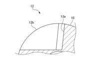
- FIG. 1 is a side view illustrating an example of a cable sheath stripping tool according to an embodiment.
- FIG. 2 is an enlarged cross-sectional view of region X in FIG.
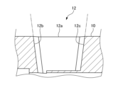
- FIG. 3 is an enlarged cross-sectional view of region Y in FIG.
- FIG. 4 is an enlarged cross-sectional view of region Z in FIG.
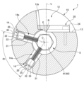
- FIG. 5 is a cross-sectional view showing the AA section of FIG.
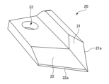
- FIG. 6 is a perspective view showing an example of a blade constituting the cable sheath stripping tool of the embodiment.
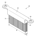
- FIG. 7 is a perspective view showing an example of a brush constituting the cable sheath stripping tool of the embodiment.
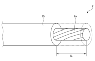
- FIG. 8 is a perspective view showing an example of a cable to be stripped by the cable sheath stripping tool of the embodiment.
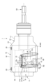
- FIG. 9 is a diagram showing a state in which a guide member is attached to the cable sheath stripping tool of FIG.
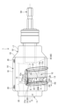
- FIG. 10 is a side view showing another example of the cable sheath stripping tool according to the embodiment.
- FIG. 11 is a side view showing another example of the cable sheath stripping tool according to the embodiment.
- the cable sheath stripping tool of the embodiment strips the sheath of a cable, which has a sheath around a conductor, while cutting it in a spiral shape with a blade.
- the cable sheath stripping tool includes a hollow main body having an insertion opening at its axial front end for inserting the cable and an outlet on its side for discharging the sheath stripped from the cable, a blade provided on the side of the main body, and a brush provided on the main body for polishing the outer periphery of the conductor of the cable from which the sheath has been stripped.
- the outlet has an axial outer wall portion extending radially outwardly of the main body portion and extending from the axial front end side to the axial rear end side of the main body portion, a front end side outer wall portion connected to the front end of the axial outer wall portion and extending radially outwardly of the main body portion, and a rear end side outer wall portion connected to the rear end of the axial outer wall portion and extending radially outwardly of the main body portion.
- FIG. 1 is a side view showing an example of a cable sheath stripping tool according to an embodiment.
- FIG. 2 is an enlarged cross-sectional view of region X in FIG. 1.
- FIG. 3 is an enlarged cross-sectional view of region Y in FIG. 1.
- FIG. 4 is an enlarged cross-sectional view of region Z in FIG. 1.
- FIG. 5 is a cross-sectional view showing the A-A section in FIG. 1.
- FIG. 2 is an enlarged cross-sectional view of the outlet 12 side of region X
- FIG. 3 is an enlarged cross-sectional view of the outlet 12 side of region Y
- FIG. 4 is an enlarged cross-sectional view of the outlet 12 side of region Z.
- the cable sheath stripping tool 1 of the embodiment includes a hollow main body 10, a blade 20, and a brush 30.
- the cable sheath stripping tool 1 strips the sheath of a cable, which has a sheath around its conductor, by cutting it in a spiral shape with the blade.
- the main body 10 is a cylindrical member centered on the axis C, and is configured so that its cross section is circular.
- the main body 10 has an insertion opening 11 for inserting a cable at its axial front end along the axis C.
- the main body 10 also has an outlet 12 on its side (circumferential surface) for discharging scraps of the coating stripped from the cable. The scraps of the coating stripped from the cable by the cable coating stripping tool 1 are curled.
- the outlet 12 of the main body 10 is connected to the internal space S of the main body 10.
- the inner diameter of the insertion opening 11 is slightly larger than the outer diameter of the cable (outer diameter of the coating) to be stripped.
- the main body 10 has a first main body 16 having an outlet 12, and a second main body 17 provided on the rear end side of the first main body 16.
- the radial outer dimension of the second main body 17 is smaller than the radial outer dimension of the first main body 16.
- the side of the main body 10 is provided with a blade attachment section 13 for attaching the blade 20.
- the blade attachment section 13 has a screw hole formed therein so that the blade 20 can be attached at a predetermined position and angle. By tilting the angle of the blade 20, it is possible to perform a process known as penciling, in which the cable coating is cut so that it gradually tapers toward the tip of the conductor. Although not shown in the figure, it is also possible to adjust the position and angle of the blade 20 by sandwiching other members such as a spacer between the blade attachment section 13 and the blade 20.
- brush attachment parts 14 for attaching brushes 30 are provided on the side of the main body 10.
- brush attachment parts 14 are provided at two locations around the circumference of the main body 10, but the installation configuration of the brush attachment parts 14 is not particularly limited, and may be only one location or three or more locations.
- the exhaust port 12 of the main body 10 has an axial outer wall portion 12a, a front end outer wall portion 12b, and a rear end outer wall portion 12c.
- the axial outer wall portion 12a extends radially outward from the main body 10, and also extends from the front end side to the rear end side of the main body 10 in the axial direction.
- the outer wall bottom 12e is connected to the inner edge of the rear end outer wall 12c.
- the discharge port 12 has the outer wall bottom 12e on the rear side of the blade body 20.
- the outer wall bottom 12e is connected to the inner edge of the rear end outer wall 12c and covers part of the internal space S leaving an opening region R described below, is parallel to the central axis C, and is made of a flat surface located radially outward of the central axis C of the first main body portion 16, and is located adjacent to the rear (rear end) of the blade body 20, covering the internal space S from the axial outer wall 12a side toward the right in the drawing.
- the front-end outer wall portion 12b is connected to the front end of the axial outer wall portion 12a and extends radially outward of the main body portion 10.
- the front-end outer wall portion 12b does not extend along the axial direction of the main body portion 10, but is connected to the front end of the axial outer wall portion 12a at a predetermined angle.
- the front-end outer wall portion 12b may be inclined toward the outside in the extension direction of the outer wall bottom portion 12e at an angle equivalent to ⁇ 2 in accordance with the mounting angle of the blade body 20, or may be connected to the front end of the axial outer wall portion 12a approximately vertically.
- the rear end outer wall portion 12c is connected to the rear end of the axial outer wall portion 12a and extends radially outward of the main body portion 10.
- the rear end outer wall portion 12c does not extend along the axial direction of the main body portion 10, but is connected to the rear end of the axial outer wall portion 12a at a predetermined angle.
- the rear end outer wall portion 12c may be inclined toward the outside in the extending direction of the outer wall bottom portion 12e at a rate equal to ⁇ 2 in accordance with the mounting angle of the blade body 20, or may be connected to the rear end of the axial outer wall portion 12a approximately vertically.
- the front end outer wall portion 12b and the rear end outer wall portion 12c face each other with a predetermined gap between them.
- the discharge port 12 has an axial outer wall portion 12a, a front end outer wall portion 12b, and a rear end outer wall portion 12c, so that the curled coating chips (hereinafter also referred to as curled coating chips) discharged from the opening region R of the discharge port 12 in the main body portion 10 continue to be discharged as chips while hitting the rear end side of the axial outer wall portion 12a and the rear end outer wall portion 12c.
- curled coating chips hereinafter also referred to as curled coating chips
- the curled coating chips discharged from the discharge port 12 are prevented from returning to the opening region R of the discharge port 12 that connects the discharge port 12 and the internal space S of the main body portion 10, and the coating chips are prevented from entering and accumulating in the internal space S of the main body portion 10, so that a decrease in work efficiency caused by removing the coating chips when performing stripping work with the cable sheath stripping tool 1 can be suppressed.
- the internal space S of the main body 10 is less likely to accumulate with cutting chips, the accumulation of cutting chips between the tip of the conductor 2a of the cable 2 and the tip surface 41 of the exposed length restriction means 40 during the peeling operation can be suppressed. Therefore, the exposed length L (see FIG. 8) of the conductor 2a in the cable 2 can be suppressed from becoming shorter than a predetermined dimension, which would be caused by the accumulation of cutting chips between the tip of the conductor 2a and the tip surface 41 of the exposed length restriction means 40.
- the axial outer wall portion 12a is inclined in a direction away from the front end outer wall portion 12b and the rear end outer wall portion 12c, as shown in Figures 2 and 3.
- the front end side outer wall portion 12b is inclined toward the front end side in the axial direction of the main body portion 10, as shown in FIG. 4. Also, from the same viewpoint, it is preferable that the connecting portion between the front end of the axial direction outer wall portion 12a and the front end side outer wall portion 12b is not angular, but has rounded corners as shown in FIG. 1.
- the rear end side outer wall portion 12c is inclined toward the rear end side in the axial direction of the main body portion 10, as shown in FIG. 4. Also, from the same viewpoint, it is preferable that the connecting portion between the rear end of the axial direction outer wall portion 12a and the rear end side outer wall portion 12c is formed not in an angular shape, but in a rounded corner shape as shown in FIG. 1, or by C-chamfering.
- a tapered section 18 having a smaller radial outer dimension from the first main body 16 toward the second main body 17 is provided.
- the coating scraps entangled around the main body 10 are removed by shifting them toward the insertion port 11. Even if the coating scraps become entangled around the rear end side of the main body 10 (the second main body 17 side), the tapered portion 18 of the main body 10 allows the coating scraps entangled at the rear end side to be smoothly shifted from the tapered portion 18 to the first main body 16, so that they can be easily removed from the main body 10.
- the main body portion 10 does not have a tapered portion 18, it is not easy to shift the coating scraps that have become entangled at the rear end side to the first main body portion 16, and it may be time-consuming to remove the coating scraps from the main body portion 10.
- the brush attachment parts 14 are arranged only in the area opposite the blade body 20 (to the left of the two-dot chain line V in FIG. 5) with respect to an imaginary plane V that passes through the tip E of the blade body 20 and is perpendicular to the extension direction of the blade body 20 (the horizontal direction in FIG. 5, which coincides with the extension direction of the top surface of the blade body attachment part 13 to which the blade body 20 is attached) when viewed from the axial direction of the main body 10.
- Each brush attachment part 14 has two screw holes so that the brush 30 can be attached at a specified position and angle.
- the brush attachment part 14 has a brush insertion hole 14a that communicates with the internal space S of the main body 10.
- the main body 10 is also provided with a restricting wall 15 that restricts the cutting width of the cable sheath.
- the restricting wall 15 is composed of a convex portion that protrudes from the inner peripheral surface of the main body 10 in the internal space S.
- the shape of the restricting wall 15 is not particularly limited as long as the restricting wall 15 can abut against the tip surface of the cable sheath and restrict the insertion of the cable.
- the axial distance between the restricting wall 15 and the cutting edge 21a of the cutting blade portion 21, which will be described later, is the cutting width of the sheath.
- Figure 6 shows the blade body 20 removed from the main body 10.
- the blade body 20 is provided on the side of the main body 10, and has a cutting edge 21 and a scooping edge 22.
- the cutting edge 21a of the cutting edge 21 and the cutting edge 22a of the scooping edge 22 are arranged perpendicular to each other so that the cross section of the blade body 20 is approximately L-shaped.
- the scooping edge 22 is provided with a through hole 23 for inserting a screw 24.
- the blade body 20 is removably fixed by a screw 24 to the blade body attachment portion 13 provided adjacent to the discharge opening 12 of the main body portion 10.
- the blade body 20 is arranged so that the cutting edge 21a of the cutting blade portion 21 and the cutting edge 22a of the scooping blade portion 22 protrude into the internal space S, and the cutting edge portion 21 of the blade body 20 is located on the insertion opening 11 side (forward) of the main body portion 10.
- FIG. 7 shows the brush 30 removed from the main body 10.
- the brush 30 is removably attached to the main body 10 and polishes the outer circumference of the conductor of the cable where the coating has been stripped off.
- the brush 30 is a so-called channel brush, and includes multiple brush wires 31 made of metal or resin and an elongated base portion 32 in which the multiple brush wires 31 are bundled and planted.
- the base portion 32 extends linearly in the longitudinal direction.
- the brush 30 also includes a mounting bracket 33 for fixing and holding the base portion 32 and attaching it to the main body 10. Through holes 34 for inserting screws 35 are formed at both longitudinal ends of the mounting bracket 33.
- the material of the brush wire 31 is not particularly limited, and may be, for example, iron or stainless steel such as SUS.
- the material of the brush wire 31 is preferably a metal such as magnesium or titanium, which has a lower tendency to ionize than aluminum, or a non-metallic material such as resin.
- the brush 30 is positioned in a range on the opposite side of the blade body 20 with respect to an imaginary plane V that passes through the tip E of the blade body 20 and is perpendicular to the extension direction of the blade body 20 when viewed from the axial direction of the main body 10.
- the brush wire 31 extends in a direction toward the axis C (in the radial direction of the main body 10).
- the tip of the brush wire 31 protrudes into the internal space S.
- the longitudinal direction of the base 32 is parallel to the axis C.
- the brush 30 is disposed in the axial direction of the main body 10 such that the end 31a of the brush wire 31 is at the same axial position as the tip E of the blade 20, or is located closer to the rear end of the main body 10 than the tip E of the blade 20. This is to polish only the outer circumference of the conductor exposed by removing the coating.
- the cable 2 to be stripped by the cable sheath stripping tool 1 is, for example, as shown in FIG. 8, a conductor 2a (made of multiple strands twisted together) made of an aluminum-based material or the like, covered with an insulator such as cross-linked polyethylene and a sheath 2b made of a vinyl sheath or the like.
- the materials of the conductor 2a and the sheath 2b are not particularly limited, and the conductor 2a may be made of a copper-based material, for example.
- the sheath 2b may be one layer as shown in FIG. 8, or two or more layers.
- the outer diameter (diameter) of the cable 2 including the sheath 2b is 13 mm or more and 34 mm or less
- the outer diameter (diameter) of the conductor 2a is 7 mm or more and 24 mm or less.
- aluminum-based materials include pure aluminum and aluminum alloys containing small amounts of additive elements (for example, copper, manganese, silicon, magnesium, zinc, nickel, iron, etc.).
- the cable sheath stripping tool 1 also includes an exposed length restriction means 40 for restricting the axial length of the sheath 2b to be stripped from the cable 2, i.e., the exposed length L of the conductor 2a (see FIG. 8).
- the exposed length restriction means 40 is disposed in the internal space S of the main body 10.
- the exposed length restriction means 40 prevents the cable 2 from being inserted any further by abutting the tip of the conductor 2a, from which the coating 2b has been stripped, against the tip surface 41. This makes it possible to restrict the exposed length L of the conductor 2a to a preset length.
- the exposed length restriction means 40 may be fixed inside the main body 10, but from the standpoint of appropriately adjusting the exposed length L of the conductor 2a, it is preferable that the exposed length restriction means 40 is provided so that its position can be adjusted in the axial direction.
- the cable sheath stripping tool 1 is also configured to be connectable to a rotary tool (not shown) such as an electric drill driver. Specifically, as shown in FIG. 1, the cable sheath stripping tool 1 is provided on the axial rear end side of the main body 10 and has a bit-shaped portion 50 extending in the axial direction.
- the bit-shaped portion 50 may be provided integrally with the exposed length restriction means 40, or may be separately provided from the exposed length restriction means 40 and detachably attached to the main body 10.
- the cable sheath stripping tool 1 When the cable sheath stripping tool 1 is used to strip the sheath 2b from the cable 2 and polish the conductor 2a, the cable sheath stripping tool 1 is used in a state where it is attached to a rotating tool (not shown), for example.
- the operator inserts the tip of the cable 2 held in one hand into the insertion port 11 of the cable sheath stripping tool 1, inserts the cable 2 until the tip surface of the sheath 2b of the cable 2 abuts against the restricting wall 15, and starts the rotating tool to rotate the cable sheath stripping tool 1 clockwise with respect to the cable 2.
- the sheath 2b of the cable 2 is helically cut by the cutting blade portion 21 of the blade body 20, while the cut sheath 2b is stripped from the conductor 2a by the scooping blade portion 22.
- the brush 30 rotates around the conductor 2a where the sheath 2b has been stripped and exposed, and the outer periphery of the conductor 2a is polished by the brush wire 31.
- the scraps of the coating 2b that have been cut in a spiral shape and peeled off are discharged from the opening region R of the discharge port 12.
- the position of the brush 30 is limited to within a predetermined range (a range on the opposite side of the blade body 20 with respect to an imaginary plane V that passes through the tip E of the blade body 20 and is perpendicular to the extension direction of the blade body 20 when viewed from the axial direction of the main body 10).
- a predetermined range a range on the opposite side of the blade body 20 with respect to an imaginary plane V that passes through the tip E of the blade body 20 and is perpendicular to the extension direction of the blade body 20 when viewed from the axial direction of the main body 10.
- the brush 30 will push the cable 2 in a direction away from the blade body 20 (to the left in FIG. 5), and the blade edge of the blade body 20 (the blade edge 21a of the cutting blade portion 21 and the blade edge 22a of the scooping blade portion 22) will not hit the cable 2 as intended, which may result in a decrease in stripping performance.
- the brush 30 is placed in a range on the opposite side of the blade body 20 with respect to the imaginary plane V, so such a decrease in stripping performance can be avoided.
- the position of the screw 24 that fixes the blade body 20 is not limited.
- the conductor 2a that comes into contact with the brush wire 31 and receives a pressing force can escape (displace) appropriately to an area where the brush 30 is not provided. Therefore, the brush wire 31 does not bite too deeply into the conductor 2a, causing uneven polishing.
- the cable sheath stripping tool 1 can therefore easily and reliably polish the outer circumference of the conductor 2a.
- the sheath stripping tool 1 is used to strip a cable 2 having an aluminum-based conductor 2a
- the sheath 2b can be stripped away and the insulating oxide film formed on the surface of the conductor 2a can be easily and reliably removed.
- an aluminum-based conductor 2a is lighter and less expensive than, for example, a copper-based conductor, the use of an aluminum-based conductor 2a can reduce the work time required to lay the cable and the material costs of the cable.
- the brushes 30 are provided at multiple locations in the circumferential direction of the main body 10. With this configuration, the outer periphery of the conductor 2a can be polished more efficiently and appropriately. From the same perspective, it is preferable that the number of brushes 30 installed is two, as shown in FIG. 5. Furthermore, when two brushes 30 are installed, it is preferable that the circumferential distance R1 between the two brushes 30 around the axis C is within the range of 30° or more and 150° or less, as shown in FIG. 5. With this configuration, the conductor 2a can be polished more effectively.
- the brush 30 is preferably disposed in the axial direction of the main body 10 so that the axial distance from the tip E of the blade body 20 shown in FIG. 1 to the end 31a of the brush wire 31 on the front side is within 5 mm.
- the brush wire 31 in an axial position close to the tip E of the blade body 20, it is possible to polish the outer periphery of the exposed conductor 2a immediately after peeling off the coating 2b.
- the axial length of the main body 10 can be reduced, and therefore the main body 10 can be made more compact. From the same viewpoint, it is most desirable that the end 31a of the brush wire 31 be disposed in the same axial position as the tip E.
- the installation range of the brush wire 31 in the axial direction of the main body 10 is 30% or more of the range from the position of the tip E of the blade 20 to the tip surface 41 of the exposed length restriction means 40.
- the size of the base 32 on which the brush wire 31 is provided is not particularly limited, and for example, the longitudinal length W of the base 32 is 25 mm, and the lateral length D of the base 32 is 5 mm.
- a guide member 60 may be attached to the discharge port 12 to guide the discharge of curled coating scraps from the discharge port 12 toward the rear end side of the main body 10.
- the guide member 60 and the blade body 20 can be fixed to the main body 10 by using a screw 24 with the guide member 60 placed so as to overlap above the blade body 20.
- the guide member 60 is a substantially triangular plate-like member, and its side surface 61 serves as a guide surface that serves as a tangle suppression means for guiding the curled coating scraps discharged from the opening region R of the discharge port 12 toward the rear end side of the main body 10.
- the curled coating scraps are discharged through between the side surface 61 of the guide member 60 and the rear end side outer wall portion 12c of the discharge port 12.
- the shape of the guide member 60 and the method of attaching the guide member 60 to the main body 10 are not limited to the illustrated example and can be changed as appropriate.
- the outer wall bottom 12e may be connected to the inner edge of the axial outer wall 12a in addition to the inner edge of the rear end outer wall 12c.
- the rear end side of the opening region R adjacent to the axial outer wall 12a of the discharge port 12 is covered by the outer wall bottom 12e, and the axial length of the part leading to the internal space S is limited to form the opening region R10.
- the axial length of the opening region R10 is limited by the outer wall bottom 12e.
- the opening region R is when the rear end side of the part adjacent to the axial outer wall 12a of the discharge port 12 is not covered by the outer wall bottom 12e and the axial length of the part leading to the internal space S is long, and the opening region R10 is when the rear end side of the part adjacent to the axial outer wall 12a of the discharge port 12 is covered by the outer wall bottom 12e and the axial length of the part leading to the internal space S is limited.
- the length of the portion of the outer wall bottom 12e adjacent to the rear of the opening region R10 in the direction of the central axis C is preferably at least half the width 20W of the blade body 20, and may be longer than the width of the blade body 20 or longer than the length of the opening region R10 in the direction of the central axis c. It is also more preferable that the opening region R10 is limited forward of the rear edge of the blade body 20 and its extension line L2, and these features may be combined. Furthermore, as shown in FIG. 11, the outer wall bottom 12e may be extended in the axial direction, for example, in the portion on the axial outer wall 12a side, to further narrow the opening region R10 in the portion facing the blade surface.
- the chips continuously discharged from the opening region R10 are sequentially curled along the surfaces of the front end outer wall portion 12b, the rear end outer wall portion 12c, and the outer wall bottom portion 12e before being discharged from the discharge port 12, so that the tip of the curled chips once discharged can be prevented from penetrating again into the main body portion 10 from the opening region R10 and accumulating there. Therefore, according to the present invention, it is possible to more reliably finish stripping the cable with the set stripping amount.
- the outlet provided in the main body has an axial outer wall portion, a front end outer wall portion, and a rear end outer wall portion, so that the cable sheath stripping tool can suppress the decrease in work efficiency associated with the cuttings of the sheath stripped from the cable and the disposal of the cuttings.
Landscapes
- Life Sciences & Earth Sciences (AREA)
- Forests & Forestry (AREA)
- Engineering & Computer Science (AREA)
- Mechanical Engineering (AREA)
- Removal Of Insulation Or Armoring From Wires Or Cables (AREA)
Abstract
ケーブル被覆剥離工具は、導線の周囲に被覆が設けられたケーブルの前記被覆を刃体により螺旋状に切断しながら剥ぎ取るケーブル被覆剥離工具であって、軸方向の前端に前記ケーブルを挿入するための挿入口を有し、側面に前記ケーブルから剥ぎ取られた被覆を排出するための排出口を有する、中空の本体部と、前記本体部の側面に設けられる刃体と、前記本体部に設けられ、前記ケーブルにおける前記被覆が剥ぎ取られた部分の導線の外周を研磨するブラシと、を備え、前記排出口は、前記本体部の径方向外側に向かって延在し、かつ前記本体部の軸方向の前端側から後端側に向かって延在する軸方向外壁部と、前記軸方向外壁部の前端に連結し、前記本体部の径方向外側に向かって延在する前端側外壁部と、前記軸方向外壁部の後端に連結し、前記本体部の径方向外側に向かって延在する後端側外壁部と、を有する。
Description
本開示は、ケーブル被覆剥離工具に関する。
従来、電力会社から分電盤までの間の幹線ケーブルには、例えば、CVケーブル、CVDケーブル、CVTケーブル、CVQケーブルなど、導線の周囲に被覆層を形成したケーブルが用いられる。CVケーブルとは、架橋ポリエチレン絶縁ビニルシースケーブルの略称である。CVケーブルは、導線と、導線の周囲に設けられた架橋ポリエチレンなどの絶縁体およびビニルシースなどの保護層を含む被覆と、を備えるケーブルである。
これらのケーブルは、施工時に、被覆を剥ぎ取り、導線を露出させて必要箇所に接続される。被覆のうち、特に架橋ポリエチレンからなる絶縁層は、硬く厚みがあり、剥ぎ取り難いことから、カッター、電工ナイフなどによる剥ぎ取り作業では、効率が悪いのみならず、作業員の怪我も発生しやすい、という問題がある。
また、アルミニウム系材料の導線を使用する場合、アルミニウム表面には、絶縁性の酸化皮膜が形成されている。そのため、ケーブルの被覆を剥離した後に、鉄製のワイヤーブラシなどを使って導電の表面を磨くことで、酸化皮膜を壊し、その内側の新生面を出す作業を行わなければならず、手間が掛かってしまうし、作業者によって仕上がりに差が生じてしまう。このため、様々なケーブル被覆剥離工具が提案されている。
例えば、特許文献1には、軸方向の一端にケーブルを挿入するための挿入口を有し、側面にケーブルから剥ぎ取られた被覆を排出する排出口を有する中空の本体部と、本体部の側面に設けられる刃体と、本体部に設けられ、被覆が剥ぎ取られた導線の外周を研磨するブラシと、を備えるケーブル被覆剥離工具が記載されている。ブラシは、本体部の軸方向から見て、刃体の先端を通り刃体の延在方向に垂直な仮想平面に対して、刃体と逆側となる範囲のみに配置されている。上記のケーブル被覆剥離工具は、ケーブルの被覆を剥離すると共に、簡単かつ確実に導線の外周を磨くことができる。
ところで、ケーブル被覆剥離工具によってケーブルから剥ぎ取られた被覆の切屑は、丸まっている(以下では、カールともいう)。そのため、本体部の排出口に形成された孔部から排出したカール状の切屑が、再び当該孔部の方に戻ってきて本体部の内部空間に入ることがある。このように、内部空間に入ってしまった切屑が、剥離作業時にケーブル導体の先端部とケーブル被覆剥離工具における露出長さ規制手段の先端面との間に挟まってしまうと、作業後の剥離長さが設定した剥ぎ代よりも短く仕上がることがあり、たとえば端子と導体との接触範囲が十分に確保できずに導通が不十分となって電気抵抗が上がってしまう可能性がある。これがさらに顕著になると、発熱に至る懸念なども考えうることから、このような懸念を避けるため、短く仕上がった導体を改めてナイフなどを使って所定の寸法に仕上げ直す場合がある。
また、剥離作業が進むにつれて、カール状に排出された切屑の長さが次第に長くなって本体部の外周に絡み付きやすくなり、巻付いた切屑によって剥離作業に支障をきたすことがある。こういった懸念を回避するために、切屑は、手で巻き取ったり、切屑の絡み方向と逆方向に本体部を回転させたりするなど、煩雑な作業によって取り除く必要があり、種々の事情によってケーブル導体の剥離作業の効率を低下させる懸念がある。
本開示の目的は、ケーブルから剥ぎ取られた被覆の切屑やその処理等に伴う作業効率の低下を抑制できるケーブル被覆剥離工具を提供することである。
[1] 導線の周囲に被覆が設けられたケーブルの前記被覆を刃体により螺旋状に切断しながら剥ぎ取るケーブル被覆剥離工具であって、軸方向の前端に前記ケーブルを挿入するための挿入口を有し、側面に前記ケーブルから剥ぎ取られた被覆を排出するための排出口を有する、中空の本体部と、前記本体部の側面に設けられる刃体と、前記本体部に設けられ、前記ケーブルにおける前記被覆が剥ぎ取られた部分の導線の外周を研磨するブラシと、を備え、前記排出口は、前記本体部の径方向外側に向かって延在し、かつ前記本体部の軸方向の前端側から後端側に向かって延在する軸方向外壁部と、前記軸方向外壁部の前端に連結し、前記本体部の径方向外側に向かって延在する前端側外壁部と、前記軸方向外壁部の後端に連結し、前記本体部の径方向外側に向かって延在する後端側外壁部と、を有する、ケーブル被覆剥離工具。
[2] 前記前端側外壁部は、前記本体部の軸方向の前端側に傾斜している、上記[1]に記載のケーブル被覆剥離工具。
[3] 前記後端側外壁部は、前記本体部の軸方向の後端側に傾斜している、上記[1]または[2]に記載のケーブル被覆剥離工具。
[4] 前記軸方向外壁部は、前記前端側外壁部および前記後端側外壁部から離れる方向に傾斜している、上記[1]~[3]のいずれか1つに記載のケーブル被覆剥離工具。
[5] 前記軸方向外壁部の後端と前記後端側外壁部との連結部分は、角丸形状またはC面取りにより形成されている、上記[1]~[4]のいずれか1つに記載のケーブル被覆剥離工具。
[6] 前記本体部において、前記排出口を備える第1本体部と、前記第1本体部よりも径方向の外形寸法が小さく、前記第1本体部の後端側に設けられる第2本体部との間には、前記第1本体部から前記第2本体部に向かって径方向の外形寸法が小さいテーパー部が設けられている、上記[1]~[5]のいずれか1つに記載のケーブル被覆剥離工具。
[7] 前記排出口は、前記刃体後方側に外壁底部を有する、上記[1]~[6]のいずれか1つに記載のケーブル被覆剥離工具。
[8] 前記排出口の開口領域の軸方向長さが、前記外壁底部によって制限されている、上記[7]に記載のケーブル被覆剥離工具。
本開示によれば、ケーブルから剥ぎ取られた被覆の切屑やその処理等に伴う作業効率の低下を抑制できるケーブル被覆剥離工具を提供することができる。
以下、実施形態に基づき詳細に説明する。
実施形態のケーブル被覆剥離工具は、導線の周囲に被覆が設けられたケーブルの被覆を刃体により螺旋状に切断しながら剥ぎ取る。ケーブル被覆剥離工具は、軸方向の前端にケーブルを挿入するための挿入口を有し、側面にケーブルから剥ぎ取られた被覆を排出するための排出口を有する、中空の本体部と、本体部の側面に設けられる刃体と、本体部に設けられ、ケーブルにおける被覆が剥ぎ取られた部分の導線の外周を研磨するブラシと、を備える。排出口は、本体部の径方向外側に向かって延在し、かつ本体部の軸方向の前端側から後端側に向かって延在する軸方向外壁部と、軸方向外壁部の前端に連結し、本体部の径方向外側に向かって延在する前端側外壁部と、軸方向外壁部の後端に連結し、本体部の径方向外側に向かって延在する後端側外壁部と、を有する。
図1は、実施形態のケーブル被覆剥離工具の一例を示す側面図である。図2は、図1の領域Xの拡大断面図である。図3は、図1の領域Yの拡大断面図である。図4は、図1の領域Zの拡大断面図である。図5は、図1のA-A断面を示す断面図である。なお、便宜上、図2は領域Xの排出口12側の拡大断面図であり、図3は領域Yの排出口12側の拡大断面図であり、図4は領域Zの排出口12側の拡大断面図である。
図1~5に示すように、実施形態のケーブル被覆剥離工具1は、中空の本体部10、刃体20およびブラシ30を備える。ケーブル被覆剥離工具1は、導線の周囲に被覆が設けられたケーブルの被覆を刃体により螺旋状に切断しながら剥ぎ取る。
本体部10は、軸線Cを中心とする筒状の部材であり、断面が円形となるように構成されている。本体部10は、軸線Cに沿う軸方向の前端に、ケーブルを挿入するための挿入口11を有する。また、本体部10は、側面(周面)に、ケーブルから剥ぎ取られた被覆の切屑を排出するための排出口12を有する。ケーブル被覆剥離工具1によってケーブルから剥ぎ取られた被覆の切屑は、カール状である。本体部10の排出口12は、本体部10の内部空間Sに連通している。挿入口11の内径は、剥離処理を施すケーブルの外径(被覆の外径)よりも僅かに大きい。
また、図1に示すように、本体部10は、排出口12を備える第1本体部16、および第1本体部16の後端側に設けられる第2本体部17を有する。第2本体部17の径方向の外形寸法は、第1本体部16の径方向の外形寸法より小さい。
また、本体部10の側面には、刃体20を取り付けるための刃体取付け部13が設けられている。刃体取付け部13には、刃体20を所定位置および所定角度に取付けることができるように、ネジ孔が形成されている。刃体20の角度を傾けることで、ケーブルの被覆を、導線の先端側に向かって徐々に先細りとなるように切削する、所謂ペンシリングと呼ばれる加工を行うことも可能である。なお、図示は省略するが、刃体取付け部13と刃体20との間にスペーサなどの他の部材を挟むことにより、刃体20の位置や角度を調整することも可能である。
また、本体部10の側面には、ブラシ30を取り付けるためのブラシ取付け部14が設けられている。ここでは、本体部10における周方向の2箇所にブラシ取付け部14が設けられているが、ブラシ取付け部14の設置構成は、特に限定されるものではなく、1箇所のみでもよいし、3箇所以上でもよい。
また、図1~4に示すように、本体部10の排出口12は、軸方向外壁部12aと前端側外壁部12bと後端側外壁部12cとを有する。軸方向外壁部12aは、本体部10の径方向外側に向かって延在し、かつ本体部10の軸方向の前端側から後端側に向かって延在する。
後端側外壁部12cの内側の縁端部には、外壁底部12eが連結されている。このように、排出口12は、刃体20後方側に外壁底部12eを有する。外壁底部12eは、後端側外壁部12cの内側の縁端部に連結されて後述する開口領域Rを残して内部空間Sの一部を覆い、中心軸Cと平行であって、第1本体部16の中心軸Cの径方向外側にある平面からなり、刃体20の後方(後端側)に隣接した部分にあって軸方向外壁部12a側から図面右方に向かって内部空間Sを覆う。
前端側外壁部12bは、軸方向外壁部12aの前端に連結し、本体部10の径方向外側に向かって延在する。前端側外壁部12bは、本体部10の軸方向に沿って延在せず、所定の角度で軸方向外壁部12aの前端に連結する。例えば、前端側外壁部12bは、刃体20の取付角度にあわせて、θ2と同程度に、外壁底部12eの延在方向外側に向けて傾斜を付けても良いし、略垂直で軸方向外壁部12aの前端に連結しても良い。
後端側外壁部12cは、軸方向外壁部12aの後端に連結し、本体部10の径方向外側に向かって延在する。後端側外壁部12cは、本体部10の軸方向に沿って延在せず、所定の角度で軸方向外壁部12aの後端に連結する。例えば、後端側外壁部12cは、刃体20の取付角度にあわせて、θ2と同程度に、外壁底部12eの延在方向外側に向けて傾斜を付けても良いし、略垂直で軸方向外壁部12aの後端に連結しても良い。前端側外壁部12bと後端側外壁部12cとは、所定の間隔をあけて対向している。
排出口12が軸方向外壁部12aと前端側外壁部12bと後端側外壁部12cとを有することで、本体部10における排出口12の開口領域Rから排出されたカール状の被覆の切屑(以下、カール状の被覆屑ともいう)は、軸方向外壁部12aの後端側や後端側外壁部12cに当たりながら、屑として排出され続ける。そのため、排出口12から排出されたカール状の被覆屑が排出口12と本体部10の内部空間Sとをつなぐ排出口12の開口領域Rに再び戻ることを防ぎ、本体部10の内部空間Sに被覆屑が侵入して溜まることが抑制されるので、ケーブル被覆剥離工具1で剥離作業を行う際に被覆の切屑を取り除くことによる作業効率の低下を抑制できる。
さらに、本体部10の内部空間Sが切屑で溜まりにくくなることから、剥離作業時に、ケーブル2の導線2aの先端と露出長さ規制手段40の先端面41との間に切屑が溜まることを抑制できる。そのため、導線2aの先端と露出長さ規制手段40の先端面41との間に切屑が溜まることに起因する、ケーブル2における導線2aの露出長さL(図8参照)が所定寸法よりも短くなることを抑制できる。
上記の効果を向上する観点から、図2~3に示すように、軸方向外壁部12aは、前端側外壁部12bおよび後端側外壁部12cから離れる方向に傾斜していることが好ましい。
同様に、上記の効果を向上する観点から、図4に示すように、前端側外壁部12bは、本体部10の軸方向の前端側に傾斜していることが好ましい。また、同様の観点から、軸方向外壁部12aの前端と前端側外壁部12bとの連結部分は、角形状ではなく、図1に示すように角丸形状であることが好ましい。
同様に、上記の効果を向上する観点から、図4に示すように、後端側外壁部12cは、本体部10の軸方向の後端側に傾斜していることが好ましい。また、同様の観点から、軸方向外壁部12aの後端と後端側外壁部12cとの連結部分は、角形状ではなく、図1に示すような角丸形状、またはC面取りにより形成されていることが好ましい。
また、本体部10において、排出口12を備える第1本体部16と、第1本体部16よりも径方向の外形寸法が小さく、第1本体部16の後端側に設けられる第2本体部17との間には、第1本体部16から第2本体部17に向かって径方向の外形寸法が小さいテーパー部18が設けられていることが好ましい。
排出口12から排出されたカール状の被覆屑が本体部10の外周に絡み付いた場合、本体部10に絡み付いた被覆屑を挿入口11側に向かってずらしながら取り除く。被覆屑が本体部10の後端側(第2本体部17側)に絡み付いたとしても、本体部10がテーパー部18を備えることで、後端側に絡み付いた被覆屑を、テーパー部18から第1本体部16にスムーズにずらせるため、本体部10から容易に取り除くことができる。
一方、本体部10がテーパー部18を備えない場合、後端側に絡み付いた被覆屑を、第1本体部16にずらすことが容易ではないため、本体部10から被覆屑を取り除く手間がかかることがある。
また、ブラシ取付け部14は、図5に示すように、本体部10の軸方向から見て、刃体20の先端Eを通り刃体20の延在方向(図5における水平方向であり、刃体20を取付ける刃体取付け部13の上面の延在方向に一致する方向)に垂直な仮想平面Vに対して、刃体20と逆側となる範囲(図5における二点鎖線Vの左側)のみに配置されている。それぞれのブラシ取付け部14には、ブラシ30を所定位置および所定角度に取付けることができるように、2つのネジ孔が形成されている。ブラシ取付け部14には、本体部10の内部空間Sに連通するブラシ挿入孔14aが形成されている。
また、本体部10には、ケーブルの被覆の切断幅を規制する規制壁15が設けられている。規制壁15は、内部空間Sにおいて、本体部10の内周面から突出する凸部で構成されている。規制壁15がケーブルの被覆の先端面を突き当ててケーブルの挿入を規制できれば、規制壁15の形状は特に限定されるものではない。規制壁15と後述する切刃部21の刃先21aとの軸方向の距離が、被覆の切断幅となる。
図6は、本体部10から取り外した状態の刃体20を示している。刃体20は、本体部10の側面に設けられ、切刃部21および掬刃部22を有する。図6に示すように、刃体20の断面が略L字状となるように、切刃部21の刃先21aおよび掬刃部22の刃先22aが互いに垂直に配置される。掬刃部22には、ネジ24を挿通するための貫通孔23が設けられている。
刃体20は、図1に示すように、本体部10の排出口12に隣接して設けられた刃体取付け部13に、ネジ24によって着脱可能に固定される。刃体20は、切刃部21の刃先21aおよび掬刃部22の刃先22aが内部空間Sに突出するように配置され、刃体20の切刃部21が本体部10の挿入口11側(前方)に位置している。
図7は、本体部10から取り外した状態のブラシ30を示している。ブラシ30は、本体部10に着脱可能に取付けられ、ケーブルにおける被覆が剥ぎ取られた部分の導線の外周を研磨する。ブラシ30は、所謂チャンネルブラシと呼ばれるものであり、金属製または樹脂製の複数本のブラシ線材31と、複数本のブラシ線材31が束ねられて植設される長尺状のベース部32とを備える。ベース部32は、長手方向に直線状に延在している。また、ブラシ30は、ベース部32を固定保持して本体部10に取付けるための取付け金具33を備えている。取付け金具33の長手方向の両端部には、ネジ35を挿通するための貫通孔34が形成されている。
ブラシ線材31の材質としては、特に限定されるものではなく、例えば、鉄やSUSなどのステンレス鋼である。また、ブラシ線材31の材質としては、電食(電蝕)を防ぐ観点から、アルミニウムよりもイオン化傾向の低いマグネシウム、チタンなどの金属、または樹脂などの非金属製であることが好ましい。
ブラシ30は、図5に示すように、本体部10の軸方向から見て、刃体20の先端Eを通り刃体20の延在方向に垂直な仮想平面Vに対して、刃体20と逆側となる範囲に配置される。
ブラシ線材31は、軸線Cに向かう方向(本体部10の径方向)に延在している。ブラシ線材31の先端は、内部空間Sに突出している。また、ベース部32の長手方向は、軸線Cと平行になっている。
また、図1に示すように、本体部10の軸方向におけるブラシ30の配設位置は、本体部10の軸方向におけるブラシ線材31の端部31aが刃体20の先端Eと同一の軸方向位置、または刃体20の先端Eよりも本体部10の後端側である。これは、被覆を剥離して露出した導線の外周のみを研磨するためである。
ケーブル被覆剥離工具1で剥離するケーブル2は、例えば図8に示すように、アルミニウム系材料製などの導線2a(複数の素線を撚り合わせてなる)の周囲を、架橋ポリエチレンなどの絶縁体、およびビニルシースなどからなる被覆2bで覆ったものである。導線2aおよび被覆2bの材質は、特に限定されるものではなく、例えば導線2aを銅系材料製としてもよい。また、被覆2bは、図8に示すように1層でもよく、2層以上でもよい。例えば、被覆2bを含むケーブル2の外径(直径)は、13mm以上34mm以下であり、導線2aの外径(直径)は、7mm以上24mm以下である。なお、アルミニウム系材料としては、例えば純アルミニウムや、アルミニウムに少量の添加元素(例えば、銅、マンガン、ケイ素、マグネシウム、亜鉛、ニッケル、鉄など)を含んだアルミニウム合金などが挙げられる。
また、ケーブル被覆剥離工具1は、ケーブル2から被覆2bを剥離する軸方向の長さ、つまり導線2aの露出長さL(図8参照)を規制するための露出長さ規制手段40を備える。
図1に示すように、露出長さ規制手段40は、本体部10の内部空間Sに配置されている。露出長さ規制手段40は、被覆2bが剥離された導線2aの先端が、先端面41に当接することで、それ以上のケーブル2の挿入を抑制する。そのため、導線2aの露出長さLを予め設定した長さに規制することができる。
露出長さ規制手段40は本体部10内に固定されてもよいが、導線2aの露出長さLを適宜調整する観点から、露出長さ規制手段40は軸方向に位置調整可能に設けられていることが好ましい。
また、ケーブル被覆剥離工具1は、電動式のドリルドライバーなどの回転工具(不図示)に接続することができるように構成されている。具体的には、図1に示すように、ケーブル被覆剥離工具1は、本体部10の軸方向の後端側に設けられ、軸方向に延在するビット状部分50を有する。ビット状部分50は、露出長さ規制手段40と一体に設けられてもよいし、露出長さ規制手段40と別体で本体部10に着脱可能に取付けられてもよい。
ケーブル被覆剥離工具1を用いてケーブル2から被覆2bを剥離し導線2aを研磨する場合には、例えば、予めケーブル被覆剥離工具1を不図示の回転工具に取付けた状態で使用する。作業者は、一方の手で把持したケーブル2の先端部をケーブル被覆剥離工具1の挿入口11に挿入し、ケーブル2の被覆2bの先端面が規制壁15に当接するまでケーブル2を挿入し、回転工具を起動してケーブル被覆剥離工具1をケーブル2に対して時計回りに回転させる。ケーブル2の周囲を本体部10が回転することにより、ケーブル2の被覆2bが刃体20の切刃部21によって螺旋状に切断されながら、切断された被覆2bが掬刃部22によって導線2aから剥ぎ取られる。被覆2bの切断および剥ぎ取りと共に、被覆2bが剥離されて露出した部分の導線2aの周囲に対して、ブラシ30が回転することで、導線2aの外周がブラシ線材31によって研磨される。螺旋状に切断され剥離された被覆2bの切屑(カール状の被覆屑)は、排出口12の開口領域Rから排出される。
また、ケーブル被覆剥離工具1では、ブラシ30の配設位置を所定の範囲(本体部10の軸方向から見て、刃体20の先端Eを通り刃体20の延在方向に垂直な仮想平面Vに対して、刃体20と逆側となる範囲)内に限定している。このように、導線2aの外周がブラシ線材31によって全周に亘って取り囲まれないため、導線2aの挿入時および取外し時、並びに本体部10の回転時において、抵抗が大きくなり過ぎることを抑制することができる。また、上記の範囲にブラシ30を配置することで、刃体20によりケーブル2から被覆2bを剥離する際の剥離性能の低下も抑制することができる。すなわち、例えば上記の範囲ではなく、仮想平面Vに対して、刃体20側となる範囲(図5における二点鎖線Vよりも右側)にブラシ30を配置した場合、ブラシ30によってケーブル2が刃体20から逃げる方向(図5の左側)に押されて、刃体20の刃先(切刃部21の刃先21aおよび掬刃部22の刃先22a)が所期したようにケーブル2に当たらず、剥離性能が低下することがある。一方、ケーブル被覆剥離工具1では、仮想平面Vに対して、刃体20の逆側となる範囲にブラシ30を配置しているため、このような剥離性能の低下は回避できる。また、上記の範囲にブラシ30を配置することで、刃体20を固定するネジ24の位置を制限することもない。
また、導線2aを研磨する過程において、ブラシ線材31に接触して押圧力を受けた導線2aは、ブラシ30が設けられていない領域に適度に逃げる(変位する)ことができる。そのため、ブラシ線材31が導線2aに食い込み過ぎて研磨にばらつきが生じることはない。
したがって、ケーブル被覆剥離工具1は、簡単かつ確実に導線2aの外周を磨くことができる。そして、アルミニウム系材料製の導線2aを有するケーブル2の剥離処理をケーブル被覆剥離工具1で行うと、被覆2bを剥離すると共に、簡単かつ確実に導線2aの表面に形成された絶縁性の酸化皮膜を除去することができる。また、アルミニウム系材料製の導線2aは、例えば銅系材料製の導線に比べて軽量で低価格であるため、アルミニウム系材料製の導線2aが使用可能となることで、ケーブル布設の作業時間およびケーブルの材料コストを削減することができる。
また、ケーブル被覆剥離工具1では、ブラシ30が本体部10の周方向における複数箇所に設けられていることが好ましい。こうした構成によれば、より効率的、かつ適度に導線2aの外周を研磨することができる。同様の観点から、ブラシ30の設置個数は図5に示すように2個であることが好ましい。さらに、ブラシ30を2個設置する場合、図5に示すように、軸線C周りにおける2個のブラシ30の周方向の間隔R1は、30°以上150°以下の範囲内であることが好ましい。こうした構成によれば、より効果的に導線2aを研磨することができる。
また、本体部10の軸方向におけるブラシ30の配設位置は、図1に示す刃体20の先端Eから前方側のブラシ線材31の端部31aまでの軸方向の距離が5mm以内となるように配置されていることが好ましい。このように、刃体20の先端Eに近い軸方向位置にブラシ線材31を配置することで、被覆2bを剥離した直後から、露出した導線2aの外周を研磨することが可能となる。また、刃体20とブラシ線材31との上記軸方向の距離を小さくすることで、本体部10が軸方向の長さを小さくすることができるため、本体部10の小型化を図ることができる。同様の観点から、ブラシ線材31の端部31aが、先端Eと同一の軸方向位置に配置されていることが最も望ましい。
また、本体部10の軸方向におけるブラシ線材31の設置範囲は、刃体20の先端Eの位置から露出長さ規制手段40の先端面41までの範囲の30%以上であることが好ましい。ブラシ線材31が設けられているベース部32の大きさは特に限定されるものではなく、例えば、ベース部32の長手方向の長さWは25mmであり、ベース部32の短手方向の長さDは5mmである。
また、切刃部21の軸線Cに垂直な平面に対する傾斜角度θ2(図1参照)が5.5°以上8.0°以下であると、切刃部21の刃先21aとケーブル2の表面との隙間が小さくなり、カール状の被覆屑が排出口12の開口領域Rに再び戻ることを抑制できる。
また、図9に示すように、排出口12からのカール状の被覆屑の排出を本体部10の後端側に向けて案内するガイド部材60を排出口12に取り付けてもよい。この場合、ガイド部材60を刃体20の上方に重ねるように配置した状態で、ネジ24を用いてガイド部材60および刃体20を共に本体部10に固定することができる。ガイド部材60は、略三角形の板状部材であり、その側面61が、排出口12の開口領域Rから排出したカール状の被覆屑を本体部10の後端側に案内する絡まり抑制手段としてのガイド面となっている。すなわち、カール状の被覆屑は、ガイド部材60の側面61と排出口12の後端側外壁部12cとの間を通って排出される。なお、ガイド部材60の形状および本体部10へのガイド部材60の取付け方法は、図示例に限定されず、適宜変更可能である。
また、図10に示すように、本発明によれば、外壁底部12eは、後端側外壁部12cの内側の縁端部に加えて、軸方向外壁部12aの内側の縁端部に連結されてもよい。この場合、開口領域Rは、排出口12の軸方向外壁部12aに隣接した部分の後端側が外壁底部12eで覆われ、内部空間Sに通じる部分の軸方向長さが制限されて開口領域R10となっている。開口領域R10の軸方向長さは、外壁底部12eによって制限されている。このように、排出口12の軸方向外壁部12aに隣接した部分の後端側が外壁底部12eで覆われず、内部空間Sに通じる部分の軸方向長さが長い場合を開口領域R、排出口12の軸方向外壁部12aに隣接した部分の後端側が外壁底部12eで覆われて、内部空間Sに通じる部分の軸方向長さが制限された場合を開口領域R10とする。
なお、ここで、外壁底部12eの開口領域R10後方に隣接した部分の中心軸C方向長さは、刃体20の幅20Wの半分以上あると好ましく、刃体20の幅よりも長くしたり、開口領域R10の中心軸c方向長さより長くしてもよい。また、刃体20の後縁部およびその延長線L2よりも前方に開口領域R10が制限されているとより好ましく、これらの特徴を組み合わせてもよい。さらに、図11に示すように、外壁底部12eは、たとえば軸方向外壁部12a側の部分について軸方向に延長して、刃面に対向した部分の開口領域R10を更に狭めるようにしてもよい。
このようにすることで、開口領域R10から連続的に送出される切屑は、前端側外壁部12b、後端側外壁部12c、外壁底部12eの各面に沿って順次カール状に形成されたのち排出口12から排出されるようになるので、一旦排出されたカール状の切屑の先端が、開口領域R10から再び本体部10の内部に入り込んで切屑がそこに溜まってしまうことを抑制することができる。そのため、本発明によれば、より確実に設定した剥き代でケーブルの皮剥きを仕上げることが可能となる。
以上説明した実施形態によれば、本体部に設けられる排出口が軸方向外壁部、前端側外壁部および後端側外壁部を有することで、ケーブル被覆剥離工具は、ケーブルから剥ぎ取られた被覆の切屑やその処理等に伴う作業効率の低下を抑制することができる。
以上、実施形態について説明したが、本発明は上記実施形態に限定されるものではなく、本開示の概念および特許請求の範囲に含まれるあらゆる態様を含み、本開示の範囲内で種々に改変することができる。
1 ケーブル被覆剥離工具
2 ケーブル
2a 導線
2b 被覆
10 本体部
11 挿入口
12 排出口
12a 軸方向外壁部
12b 前端側外壁部
12c 後端側外壁部
12e 外壁底部
13 刃体取付け部
14 ブラシ取付け部
14a ブラシ挿入孔
15 規制壁
16 第1本体部
17 第2本体部
18 テーパー部
20 刃体
20W 刃体の幅
21 切刃部
21a 切刃部の刃先
22 掬刃部
22a 掬刃部の刃先
23 貫通孔
24 ネジ
30 ブラシ
31 ブラシ線材
31a ブラシ線材の端部
32 ベース部
33 取付け金具
34 貫通孔
35 ネジ
40 露出長さ規制手段
41 先端面
50 ビット状部分
60 ガイド部材
61 側面
C 軸線
E 刃体の先端
L 露出長さ
L2 刃体の後縁部およびその延長線
V 仮想平面
R、R10 開口領域
S 内部空間
X、Y 領域
Claims (8)
- 導線の周囲に被覆が設けられたケーブルの前記被覆を刃体により螺旋状に切断しながら剥ぎ取るケーブル被覆剥離工具であって、
軸方向の前端に前記ケーブルを挿入するための挿入口を有し、側面に前記ケーブルから剥ぎ取られた被覆を排出するための排出口を有する、中空の本体部と、
前記本体部の側面に設けられる刃体と、
前記本体部に設けられ、前記ケーブルにおける前記被覆が剥ぎ取られた部分の導線の外周を研磨するブラシと、を備え、
前記排出口は、
前記本体部の径方向外側に向かって延在し、かつ前記本体部の軸方向の前端側から後端側に向かって延在する軸方向外壁部と、
前記軸方向外壁部の前端に連結し、前記本体部の径方向外側に向かって延在する前端側外壁部と、
前記軸方向外壁部の後端に連結し、前記本体部の径方向外側に向かって延在する後端側外壁部と、
を有する、ケーブル被覆剥離工具。 - 前記前端側外壁部は、前記本体部の軸方向の前端側に傾斜している、請求項1に記載のケーブル被覆剥離工具。
- 前記後端側外壁部は、前記本体部の軸方向の後端側に傾斜している、請求項1に記載のケーブル被覆剥離工具。
- 前記軸方向外壁部は、前記前端側外壁部および前記後端側外壁部から離れる方向に傾斜している、請求項1に記載のケーブル被覆剥離工具。
- 前記軸方向外壁部の後端と前記後端側外壁部との連結部分は、角丸形状またはC面取りにより形成されている、請求項1に記載のケーブル被覆剥離工具。
- 前記本体部において、前記排出口を備える第1本体部と、前記第1本体部よりも径方向の外形寸法が小さく、前記第1本体部の後端側に設けられる第2本体部との間には、前記第1本体部から前記第2本体部に向かって径方向の外形寸法が小さいテーパー部が設けられている、請求項1~5のいずれか1項に記載のケーブル被覆剥離工具。
- 前記排出口は、前記刃体後方側に外壁底部を有する、請求項1に記載のケーブル被覆剥離工具。
- 前記排出口の開口領域の軸方向長さが、前記外壁底部によって制限されている、請求項7に記載のケーブル被覆剥離工具。
Priority Applications (1)
| Application Number | Priority Date | Filing Date | Title |
|---|---|---|---|
| JP2025550394A JPWO2025075196A1 (ja) | 2023-10-06 | 2024-10-07 |
Applications Claiming Priority (2)
| Application Number | Priority Date | Filing Date | Title |
|---|---|---|---|
| JP2023-174752 | 2023-10-06 | ||
| JP2023174752 | 2023-10-06 |
Publications (1)
| Publication Number | Publication Date |
|---|---|
| WO2025075196A1 true WO2025075196A1 (ja) | 2025-04-10 |
Family
ID=95283610
Family Applications (1)
| Application Number | Title | Priority Date | Filing Date |
|---|---|---|---|
| PCT/JP2024/035838 Ceased WO2025075196A1 (ja) | 2023-10-06 | 2024-10-07 | ケーブル被覆剥離工具 |
Country Status (2)
| Country | Link |
|---|---|
| JP (1) | JPWO2025075196A1 (ja) |
| WO (1) | WO2025075196A1 (ja) |
Citations (4)
| Publication number | Priority date | Publication date | Assignee | Title |
|---|---|---|---|---|
| JP2000288271A (ja) * | 1999-04-02 | 2000-10-17 | Kyushu Electric Power Co Inc | 被覆屑落下防止付き電線皮剥ぎ器 |
| JP2001268740A (ja) * | 2000-03-15 | 2001-09-28 | Toenec Corp | 充電式ケーブル被覆剥取機 |
| JP3151876U (ja) * | 2009-04-27 | 2009-07-09 | 株式会社きんでん | 絶縁被覆剥取工具 |
| JP2019193477A (ja) * | 2018-04-26 | 2019-10-31 | 株式会社Tjmデザイン | ケーブル被覆剥離工具 |
-
2024
- 2024-10-07 WO PCT/JP2024/035838 patent/WO2025075196A1/ja not_active Ceased
- 2024-10-07 JP JP2025550394A patent/JPWO2025075196A1/ja active Pending
Patent Citations (4)
| Publication number | Priority date | Publication date | Assignee | Title |
|---|---|---|---|---|
| JP2000288271A (ja) * | 1999-04-02 | 2000-10-17 | Kyushu Electric Power Co Inc | 被覆屑落下防止付き電線皮剥ぎ器 |
| JP2001268740A (ja) * | 2000-03-15 | 2001-09-28 | Toenec Corp | 充電式ケーブル被覆剥取機 |
| JP3151876U (ja) * | 2009-04-27 | 2009-07-09 | 株式会社きんでん | 絶縁被覆剥取工具 |
| JP2019193477A (ja) * | 2018-04-26 | 2019-10-31 | 株式会社Tjmデザイン | ケーブル被覆剥離工具 |
Also Published As
| Publication number | Publication date |
|---|---|
| JPWO2025075196A1 (ja) | 2025-04-10 |
Similar Documents
| Publication | Publication Date | Title |
|---|---|---|
| JP7549920B2 (ja) | ケーブル被覆剥離工具 | |
| CA2587542C (en) | Compression connector assembly | |
| KR101652663B1 (ko) | 지중케이블용 수동 피박기 및 그 피박기를 이용한 지중케이블 피박공법 | |
| US20060102375A1 (en) | Stepped compression connector | |
| JP6017202B2 (ja) | ケーブル被覆剥取工具 | |
| WO2025249445A1 (ja) | ケーブル被覆剥離工具 | |
| KR200452089Y1 (ko) | 충실형 케이블 피복 탈피기 | |
| US3548690A (en) | Tool for removing cable insulation | |
| JP6788883B2 (ja) | ケーブル被覆剥離工具 | |
| KR102960029B1 (ko) | 케이블 중간 접속 구조의 형성 방법 및 케이블 중간 접속 구조 | |
| JP7510325B2 (ja) | 接続クランプ装置 | |
| JPH11329100A (ja) | コンパクト型電力ケーブル | |
| EP0188520A1 (en) | A shield stripper for electrical wiring | |
| CN217097113U (zh) | 一种全封闭防尘电动剥线装置 | |
| JP3065265B2 (ja) | 被覆剥取器 | |
| US12206226B2 (en) | Cable stripping tool | |
| JP3151877U (ja) | 絶縁被覆剥取工具 | |
| JP6798959B2 (ja) | 剥離用工具 | |
| CN221885893U (zh) | 一种电力工程用电力线缆剥线装置 | |
| CN214506375U (zh) | 一种剪剥两用的组合式刀具 | |
| JP2021034300A (ja) | ワイヤハーネス | |
| KR102546362B1 (ko) | 퀵 타입 와이어 컨넥터 | |
| JP7244920B2 (ja) | 電線皮剥工具 | |
| JP3572478B2 (ja) | 金属被覆ケーブル | |
| JPH0667082B2 (ja) | ケ−ブル外被の剥取り工具 |
Legal Events
| Date | Code | Title | Description |
|---|---|---|---|
| 121 | Ep: the epo has been informed by wipo that ep was designated in this application |
Ref document number: 24874795 Country of ref document: EP Kind code of ref document: A1 |
|
| ENP | Entry into the national phase |
Ref document number: 2025550394 Country of ref document: JP Kind code of ref document: A |
|
| WWE | Wipo information: entry into national phase |
Ref document number: 2025550394 Country of ref document: JP |
|
| WWE | Wipo information: entry into national phase |
Ref document number: 112024004193 Country of ref document: DE |