WO2025069979A1 - 生体検出装置 - Google Patents
生体検出装置 Download PDFInfo
- Publication number
- WO2025069979A1 WO2025069979A1 PCT/JP2024/031857 JP2024031857W WO2025069979A1 WO 2025069979 A1 WO2025069979 A1 WO 2025069979A1 JP 2024031857 W JP2024031857 W JP 2024031857W WO 2025069979 A1 WO2025069979 A1 WO 2025069979A1
- Authority
- WO
- WIPO (PCT)
- Prior art keywords
- radar
- living body
- vehicle
- absence
- detection device
- Prior art date
- Legal status (The legal status is an assumption and is not a legal conclusion. Google has not performed a legal analysis and makes no representation as to the accuracy of the status listed.)
- Pending
Links
Images


Classifications
-
- G—PHYSICS
- G01—MEASURING; TESTING
- G01S—RADIO DIRECTION-FINDING; RADIO NAVIGATION; DETERMINING DISTANCE OR VELOCITY BY USE OF RADIO WAVES; LOCATING OR PRESENCE-DETECTING BY USE OF THE REFLECTION OR RERADIATION OF RADIO WAVES; ANALOGOUS ARRANGEMENTS USING OTHER WAVES
- G01S13/00—Systems using the reflection or reradiation of radio waves, e.g. radar systems; Analogous systems using reflection or reradiation of waves whose nature or wavelength is irrelevant or unspecified
- G01S13/02—Systems using reflection of radio waves, e.g. primary radar systems; Analogous systems
- G01S13/04—Systems determining presence of a target
-
- G—PHYSICS
- G01—MEASURING; TESTING
- G01S—RADIO DIRECTION-FINDING; RADIO NAVIGATION; DETERMINING DISTANCE OR VELOCITY BY USE OF RADIO WAVES; LOCATING OR PRESENCE-DETECTING BY USE OF THE REFLECTION OR RERADIATION OF RADIO WAVES; ANALOGOUS ARRANGEMENTS USING OTHER WAVES
- G01S13/00—Systems using the reflection or reradiation of radio waves, e.g. radar systems; Analogous systems using reflection or reradiation of waves whose nature or wavelength is irrelevant or unspecified
- G01S13/87—Combinations of radar systems, e.g. primary radar and secondary radar
Definitions
- the disclosure in this specification relates to a biological detection device.
- Patent Document 1 discloses an occupant detection device equipped with a radar that transmits pulse waves and receives reflected waves.
- the contents of the prior art document are incorporated by reference as explanations of the technical elements in this specification.
- This disclosure has been made in consideration of these issues, and aims to provide a living body detection device that can improve the accuracy of detecting living bodies inside a vehicle.
- a biological detection device includes: At least one radar mounted on a vehicle, transmitting a pulse wave of a predetermined frequency and receiving a reflected wave of the pulse wave; a detection unit that detects the presence or absence of a living body inside the vehicle based on a received signal from the radar; Equipped with The radar transmits and receives signals multiple times at predetermined intervals.
- the reception time of the reflected wave is longer than the time corresponding to the distance between the radar and the farthest position from the radar at the end of the vehicle,
- the detection unit detects the presence or absence of a living body based on the received signals from multiple transmissions and receptions.
- the disclosed living body detection device performs transmission and reception multiple times, and detects the presence or absence of a living body based on the multiple received signals. By lengthening the reception time, the radar receives indirect waves from the living body that pass through the metal object of the vehicle. In this way, multipath is actively utilized. Even if sampling variations occur due to indirect waves that are received with a delay compared to the direct waves from the metal object, the presence or absence of a living body can be detected. This makes it possible to improve the accuracy of detecting a living body inside the vehicle.
- FIG. 2 is a diagram illustrating a detection principle.
- FIG. 2 is a diagram showing an example of a radar received waveform.
- FIG. 4 is a diagram showing temporal variations in the reception strength of a reflected wave.
- FIG. 2 is a diagram showing a mounting position of a radar on a vehicle.
- FIG. 13 is a diagram showing the results of measuring reflection intensity.
- FIG. 6 is a diagram in which the time shown in FIG. 5 is replaced with distance.
- 13 is a diagram showing temporal variations in the reception strength of reflected waves when a child is present in seat P.
- FIG. FIG. 8 is a diagram showing a waveform obtained by subjecting the waveform of FIG. 7 to a filter process.
- FIG. 13 is a diagram showing sampling variations in multiple transmissions and receptions.
- FIG. 1 is a diagram showing sampling variations in multiple transmissions and receptions.
- FIG. 13 is a diagram showing temporal variations in the reception strength of reflected waves when a child is present in the trunk.
- FIG. 11 is a diagram showing a waveform obtained by subjecting the waveform of FIG. 10 to filtering processing.
- 1 is a diagram showing a biological detection device according to a first embodiment
- FIG. 13 is a diagram showing an indirect wave passing from a living body through a metal body.
- 13 is a flowchart showing a living body detection process.
- FIG. 13 is a diagram showing the time variation of the reception intensity at point SP1.
- FIG. 16 is a diagram showing a waveform obtained by subjecting the waveform of FIG. 15 to a filter process.
- 10 is a flowchart showing a living body detection process executed by a living body detection device according to a second embodiment.
- FIG. 13 is a flowchart showing a living body detection process executed by a living body detection device according to a third embodiment.
- FIG. 13 is a flowchart showing a living body detection process executed by a living body detection device according to a fourth embodiment.
- FIG. 1 is a diagram illustrating an example of the displacement of a moving object relative to a radar.
- FIG. 13 is a diagram showing a change in relative velocity.
- FIG. 13 is a diagram showing an example of radar arrangement in a living body detection device according to a fifth embodiment.
- 13 is a flowchart showing a living body detection process.
- 1A and 1B are diagrams showing received waveforms of one pulse from an in-vehicle radar and an external radar;
- FIG. 23 is a diagram showing an example of mounting positions of a plurality of radars on a vehicle in a living body detection device according to a sixth embodiment.
- FIG. 11 is a diagram showing a living body detection process.
- EuroNCAP is an abbreviation for European New Car Assessment Program.
- the living body detection device detects the presence or absence of a living body inside a vehicle using pulse waves as described below.
- the living body detection device can be used, for example, to detect children left behind.
- Living bodies inside a vehicle that can be detected by the living body detection device are not limited to children, but can also include passengers other than children, and animals such as dogs and cats.
- Fig. 1 shows the detection principle.
- Fig. 1 shows the displacement of the body surface due to breathing.
- the transmitted pulse wave (transmitted wave) is shown by a solid arrow
- the reflected wave by the human body is shown by a dashed arrow
- the transmitted wave passing through the human body is shown by a two-dot chain arrow.
- Fig. 2 shows an example of a radar received waveform.
- Fig. 3 shows the time variation of the reception strength of the reflected wave.
- Fig. 3 shows the time change of the reception strength in multiple transmissions and receptions.
- a human body is shown as an example of the living body 100.
- a high-frequency pulse wave is irradiated from the radar 30 to a living body 100 (human body)
- part of the wave passes through the living body 100 and the other part is reflected by the body surface 100s.
- the high-frequency wave is, for example, a frequency of 1 GHz or higher.
- the radar 30 is, for example, a UWB radar.
- UWB is an abbreviation for Ultra Wide Band. Since the body surface 100s is displaced by breathing, the distance between the radar 30 (antenna) and the living body 100 changes in response to breathing.
- the displacement ⁇ d of the body surface 100s due to breathing is, for example, about 1 mm to 10 mm.
- Figure 2 shows the received waveform at a specified transmission and reception timing.
- a waveform showing the time variation of the received strength of the reflected wave shown in Figure 3 can be obtained.
- the time variation shown in Figure 3 is specific to the respiration of the living body 100. Therefore, the presence or absence of a living body can be detected using the time variation. Body movement can also be detected by monitoring the received waveform, as the distance between the radar 30 and the living body 100 changes.
- FIG. 4 shows the mounting position of the radar (UWB radar) when the reflection intensity was measured.
- FIG. 5 shows the result of measuring the reflection intensity.
- FIG. 6 shows the time shown in FIG. 5 replaced with the distance.
- FIG. 6 shows the distance as half the distance (round-trip distance) corresponding to the reception intensity, that is, the one-way distance.
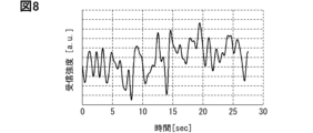
- FIG. 7 shows the time variation of the reception intensity of the reflected wave when a child (living body) is present in the P seat.
- FIG. 7 corresponds to FIG. 3.
- FIG. 7 shows the time variation of the reception intensity when a child is present at distance L1.
- FIG. 8 shows the waveform obtained by subjecting FIG. 7 to filtering.
- FIG. 8 shows the waveform after frequency filtering (0.1 to 1 Hz).
- FIG. 9 shows the sampling variation in multiple transmissions and receptions.
- the received waveform in Figure 5 shows the waveform (base waveform) when no living body is present inside the vehicle.
- the time on the horizontal axis shows the elapsed time from the transmission of the pulse wave to the reception of the reflected wave, that is, the reception time.
- the areas where the reception intensity is high near time zero (0) are due to reflections (direct waves) from the metal ceiling.
- the received waveform is superimposed not only on the ceiling, but also on reflections from metal objects such as the body, depending on the distance from the radar 30. In areas where the reception time is short, the influence of the direct wave from the metal object is large, and the reception intensity is high.
- the dashed dotted lines in Figure 6 indicate the positions of the front seats (seat D, seat P), rear seats (behind seat D, behind seat P), and the trunk.
- the front seats are located at a distance L1 from the radar 30.
- the rear seats are located at a distance L2 from the radar 30.
- the trunk is located at a distance L3 from the radar 30. Distances L1, L2, and L3 satisfy the relationship L1 ⁇ L2 ⁇ L3.
- Seat D is the driver's seat
- seat P is the passenger seat.
- reception strength the greater the effect of this variability. For example, if a child is seated in a location where the effects of reflection from the ceiling remain (such as the front seat), minute variations such as breathing will be lost in the changes in reception strength caused by sampling variability. In this way, it has become clear that there is a risk that the variation caused by a living body will be lost in the changes caused by sampling variability, and the living body may not be detected.
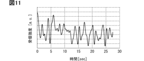
- Figure 10 shows the time variation in the reception strength of the reflected wave when a child is present in the trunk.
- Figure 10 corresponds to Figure 3.
- Figure 10 shows the time variation in the reception strength when a child is present at distance L3.
- Figure 11 shows the waveform after filtering has been applied to Figure 10.
- Figure 11 shows the waveform after frequency filtering (0.1 to 1 Hz).
- the living body detection device is based on the above findings. Next, the general configuration of the living body detection device will be described.
- Fig. 12 shows a schematic configuration of a living body detection device according to this embodiment.
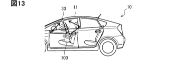
- Fig. 13 shows an indirect wave.
- the living body detection device 20 includes at least one radar 30 and an ECU 40.
- ECU is an abbreviation for Electronic Control Unit.
- the ECU 40 is sometimes called an electronic control device.
- the radar 30 transmits pulse waves of a predetermined frequency and receives reflected waves of the pulse waves.
- the radar 30 has an antenna 31.
- the antenna 31 may include a transmitting antenna and a receiving antenna, or may include an antenna for both transmitting and receiving.
- the frequency of the pulse waves is high frequency, for example, a frequency of 1 GHz or higher, as described above.
- the radar 30 is a UWB radar or a millimeter wave radar.
- the radar 30 of this embodiment is an IR type UWB radar.
- IR is an abbreviation for Impulse Radio.
- the impulse signal used in UWB communication may be a signal with an extremely short pulse width (for example, 2 ns) and a bandwidth of 500 MHz (strictly speaking, 499.2 MHz) or more, that is, an ultra-wide bandwidth.
- the radar 30 is attached to the vehicle 10.
- the living body detection device 20 may include only one radar 30, or may include multiple radars 30.
- the living body detection device 20 of this embodiment includes only one radar 30.
- the radar 30 is disposed inside the vehicle near the front end of the ceiling 11 and near the center in the left-right direction.
- the radar 30 is disposed in the overhead console.
- the radar 30 may be used in combination with the radar of a smart entry system, for example.
- the antenna 31 may be, for example, an omnidirectional antenna.
- the radar 30 performs transmission and reception multiple times at a predetermined interval during the living body detection period described below.
- the radar 30 performs multiple transmission and reception at a time interval that is sufficiently short with respect to the breathing cycle.
- the reception time of the reflected wave is longer than the time corresponding to the distance between the radar 30 and the position at the end of the vehicle 10 that is the furthest from the radar 30. Therefore, as shown in FIG. 13, the radar 30 receives indirect waves that pass from the living body through the metal body of the vehicle 10. In this way, the living body detection device 20 actively uses multipath.
- the vehicle 10 is a five-seater passenger car.
- the end of the vehicle 10 that is the furthest from the radar 30 is the rear end of the vehicle, and the distance from the radar 30 to the rear end of the vehicle is about 2 m.
- the reception time of the reflected wave is longer than the time corresponding to the distance of 2 m to the rear end of the vehicle.
- the reception time may be, for example, a time (about 13 ns) corresponding to a round-trip distance of 4 m between the radar 30 and the rear end of the vehicle.
- the radar 30 may wait 100 ms before performing the next transmission or reception.
- the ECU 40 controls the operation of the radar 30.
- the ECU 40 detects the presence or absence of a living body inside the vehicle based on the signal received by the radar 30.
- the ECU 40 corresponds to the detection unit.
- the ECU 40 detects the presence or absence of a living body based on multiple received signals.
- the ECU 40 of this embodiment detects the presence or absence of a living body based on the amount of time variation of multiple received signals.
- the ECU 40 is configured with a processor 41, a memory 42, a storage 43, and the like.
- the processor 41 executes various processes by accessing the memory 42.
- the memory 42 is a rewritable volatile storage medium.
- the memory 42 is, for example, a RAM.
- RAM is an abbreviation for Random Access Memory.
- the storage 43 is a rewritable non-volatile storage medium.
- the storage 43 stores programs executed by the processor 41.
- the ECU 40 executes programs while accessing the memory to construct multiple functional units.
- the execution of a program by the processor 41 corresponds to the execution of a living body detection method described below.
- the ECU 40 may include multiple processors 41.
- the ECU 40 may also be used as an ECU for a smart entry system, for example.
- the ECU 40 may include a function to detect the presence or absence of a living body inside the vehicle together with the radar 30, such as a function to detect whether a child has been left behind.
- ⁇ Body detection method> 14 is a flowchart showing a process executed by the living body detection device, that is, a living body detection method.
- the living body detection device 20 executes the living body detection process shown in FIG.
- the ECU 40 controls the operation of the radar 30 so that the transmission and reception process is performed for a predetermined period (step S10).
- the radar 30 performs the transmission and reception process.
- the predetermined period is 10 seconds from the door lock.
- the radar 30 repeatedly performs multiple transmissions and receptions at predetermined intervals.
- the reception time for one transmission is 13 ns, and multiple transmissions and receptions are performed at intervals of 100 ms.
- the ECU 40 acquires a number of received signals from the radar 30 during the above-mentioned predetermined period, and starts loop processing (step S20).
- the ECU 40 executes loop processing in sequence for preset sampling points.
- the sampling points are, for example, predetermined distance values as shown in FIG. 6, or predetermined time values as shown in FIG. 5. Multiple sampling points may be set for each predetermined distance or each predetermined time.
- the sampling points may be set, for example, every 0.1 m, or every 1 ns.
- the sampling points may be set based on data obtained from testing, etc.
- the ECU 40 calculates the time variation of the reception strength at a specified sampling point, i.e., the amplitude (step S30). Next, the ECU 40 compares the calculated amplitude with a threshold value and determines whether the amplitude is greater than the threshold value (step S40). As described above, the reception strength of the base waveform is generally greater the closer it is to the radar 30.
- the threshold value is set according to the sampling point. The threshold value is set according to the amplitude of the base waveform. The threshold value is set taking into account sampling variability, i.e., variability in the reception strength of the base waveform. This makes it possible to suppress erroneous judgments.
- the ECU 40 executes the processing of steps S30 and S40 for the next sampling point. If the amplitude is below the threshold for all sampling points, the ECU 40 ends the loop processing (step S50). The ECU 40 then determines that no living body 100 is present inside the vehicle (step S60), and ends the series of processes. If the amplitude is greater than the threshold in step S40, the ECU 40 determines that breathing or body movement is superimposed on the base waveform, i.e., that a living body 100 is present inside the vehicle (step S70), and ends the series of processes.
- the ECU 40 detects the presence or absence of a living body 100 based on the time variation in the reception strength at the sampling point.
- the direct wave from a metal object such as the ceiling 11 is superimposed on the sampled reflected wave immediately after transmission. Therefore, variations such as breathing are easily masked by changes in reception strength caused by sampling variance.
- the influence of the direct wave from the metal body has weakened, and a waveform is observed in which the reflected wave from the living body 100 is further diffusely reflected inside the vehicle body and reaches the radar 30.
- the indirect wave that travels from the living body 100 through the metal body reaches the radar 30 later than the direct wave from the metal body. Therefore, fluctuations such as respiration are more likely to appear than in places where the reflection strength of the base waveform is high.
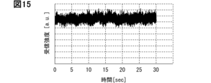
- FIG. 15 shows the time variation of the reception intensity at sampling point SP1 shown by the two-dot chain line in FIG. 6.
- FIG. 15 corresponds to FIG. 3.
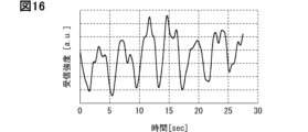
- FIG. 16 shows the waveform after filtering of FIG. 15. Like FIG. 8, FIG. 16 shows the waveform after frequency filtering (0.1 to 1 Hz).
- Sampling point SP1 is at a distance longer than 2 m to the rear end of the vehicle, for example 2.4 m. The distance of sampling point SP1 is longer than twice the distance of the front seat (distance L1).
- ECU 40 includes sampling point SP1 as a sampling point.
- the influence of the direct wave from the metal body is weakened, and an indirect wave passing through the metal body from the living body 100 is observed.
- the variation due to breathing appears as an amplitude.
- the direct wave may attenuate as described above and may not reach the living body 100 present in the trunk.
- the pulse wave may reach the living body 100 via a reflection path on the floor, etc., and the reflected wave from the living body 100 may be diffused inside the vehicle body and reach the radar 30. Therefore, as described above, at the sampling point where the influence of the direct wave from the metal body is weakened, it is possible to detect fluctuations due to breathing, etc.
- the radar 30 performs transmission and reception multiple times, and the ECU 40 (detection unit) detects the presence or absence of the living body 100 based on the multiple received signals.
- the reception time of the reflected wave is longer than the time corresponding to the distance between the radar 30 and the position at the end of the vehicle 10 that is farthest from the radar 30.
- the radar 30 receives an indirect wave that passes from the living body 100 through the metal body of the vehicle 10. In this way, multipath is actively utilized.
- the influence of the direct waves from the metal object is small, and for example the reception strength of the base waveform is low. Therefore, as shown in FIG. 9, even if there is a time lag of the order of nanoseconds due to multiple receptions, that is, sampling variation, it is possible to detect the presence or absence of the living body 100. This makes it possible to improve the detection accuracy of the living body 100 inside the vehicle. For example, it is possible to improve the accuracy of detecting whether a child has been left behind.
- the ECU 40 may detect the presence or absence of the living body 100 based on the time variation in the reception strength over multiple receptions, i.e., the amplitude. Fluctuations such as respiration and body movement are superimposed on the base waveform. In other words, the amplitude increases by the amount of respiration and body movement. Therefore, the presence or absence of the living body 100 can be detected based on the amplitude. By using the amplitude, it is possible to detect not only respiration but also fluctuations due to body movement.
- a UWB radar may be used as the radar 30.
- UWB uses radio waves compressed into a pulse shape to measure the communication time between the smartphone and the car to identify the smartphone's location and use this as a trigger for opening and closing the car key and starting the engine.
- a millimeter wave radar may be used instead of a UWB radar.
- This embodiment is a modification of the previous embodiment as a basic form, and the description of the previous embodiment can be used.
- the presence or absence of a living body is detected based on the amplitude. Instead of this, the presence or absence of a living body may be detected based on the frequency characteristic.
- FIG. 17 shows the process executed by the living body detection device according to this embodiment, that is, the living body detection method.
- the processes of steps S130 and S140 are different from the processes of steps S30 and S40 shown in FIG. 14.
- the other processes are the same as the processes shown in FIG. 14.
- the biodetection device 20 executes the biodetection process shown in FIG. 17.
- the processes of steps S110 and S120 are the same as the processes of steps S10 and S20 shown in FIG. 14.
- the ECU 40 calculates the frequency characteristics (step S130).
- the ECU 40 calculates the frequency characteristics based on, for example, the time fluctuation of the reception strength at a predetermined sampling point.
- the ECU 40 calculates the frequency characteristics by using a fast Fourier transform (FFT) on the time fluctuation (amplitude) of the reception strength.
- FFT fast Fourier transform
- the ECU 40 calculates, for example, kurtosis as the frequency characteristic. Kurtosis is the reception strength at the peak frequency divided by the average strength of the other frequencies.
- the ECU 40 compares the calculated kurtosis with a threshold value and determines whether the kurtosis is greater than the threshold value (step S140). If the kurtosis is equal to or less than the threshold value, the ECU 40 executes the processing of steps S130 and S140 for the next sampling point. If the kurtosis is equal to or less than the threshold value for all sampling points, the ECU 40 ends the loop processing (step S150), determines that a living body 100 is not present in the vehicle (step S160), and ends the series of processes.
- the processing of step S150 is the same as the processing of step S50.
- the processing of step S160 is the same as the processing of step S60.
- step S170 the ECU 40 detects breathing, i.e., determines that a living body 100 is present inside the vehicle (step S170), and ends the series of processes.
- the process of step S170 is the same as the process of step S70.
- the other configurations are the same as those described in the preceding embodiment.
- the ECU 40 may detect the presence or absence of a living body 100 based on the frequency characteristics of the signal received multiple times. The presence or absence of a living body 100 can be detected based on whether or not the frequency characteristics are specific to breathing.
- This embodiment is a modification based on the previous embodiment, and the description of the previous embodiment can be used.
- the presence or absence of a living body is detected based on the amplitude or frequency characteristics.
- the presence or absence of a living body may be detected based on the amplitude and frequency characteristics.
- FIG. 18 shows the process executed by the living body detection device according to this embodiment, that is, the living body detection method.
- the living body detection process shown in FIG. 18 is configured by adding steps S130 and S140 in FIG. 17 to the process shown in FIG. 14.
- the biodetection device 20 executes the biodetection process shown in FIG. 18.
- the processes of steps S210, S220, S230, and S240 are similar to the processes of steps S10, S20, S30, and S40 shown in FIG. 14.
- the ECU 40 calculates the frequency characteristic (step S250).
- the ECU 40 calculates, for example, kurtosis as the frequency characteristic.
- the ECU 40 determines whether the kurtosis is greater than the kurtosis threshold (step S260).
- the processes of steps S250 and S260 are similar to the processes of steps S130 and S140 shown in FIG. 17.
- the ECU 40 executes the process from step S230 onwards for the next sampling point. If the amplitude is equal to or less than the amplitude threshold and the kurtosis is equal to or less than the kurtosis threshold for all sampling points, the ECU 40 ends the loop process (step S270), determines that a living body 100 is not present inside the vehicle (step S280), and ends the series of processes.
- the processes of steps S270 and S280 are the same as the processes of steps S50 and S60.
- step S290 the ECU 40 determines that the living body 100 is present in the vehicle (step S290) and ends the series of processes. If the kurtosis is greater than the kurtosis threshold in step S260, the ECU 40 also executes the process of step S290 and ends the series of processes.
- the process of step S290 is the same as the process of step S70. The other configurations are the same as those described in the preceding embodiment.
- the ECU 40 may first determine the presence or absence of a living organism 100 based on the time fluctuations of multiple received signals, i.e., the amplitude, and if the living organism 100 is not detected based on the amplitude, then determine the presence or absence of the living organism 100 based on the frequency characteristics of the multiple received signals.
- the amplitude as described above, it is possible to detect not only fluctuations due to breathing of the living organism 100, but also fluctuations due to body movement.
- minute fluctuations due to breathing are buried in fluctuations in the received signal due to sampling variance and the living organism 100 cannot be detected based on the amplitude, it is possible to detect breathing, i.e., detect the living organism 100, by using the frequency characteristics. In other words, the accuracy of detecting the living organism 100 inside the vehicle can be further improved.
- the ECU 40 may first detect the presence or absence of the living body 100 based on the amplitude, and when the living body 100 is detected based on the amplitude, detect the presence or absence of the living body 100 based on the frequency characteristics of the received signal multiple times. As shown in FIG. 19, the ECU 40 judges whether the amplitude is greater than the amplitude threshold (step S240), and calculates the frequency characteristics when the amplitude is greater than the amplitude threshold (step S250). The ECU 40 judges whether the kurtosis is greater than the kurtosis threshold (step S260), and when the kurtosis is greater than the kurtosis threshold, it determines that a living body is present (step S290).
- the loop process is executed until there are no more sampling points, and when there are no more sampling points, the loop process is terminated (step S270), and it is determined that there is no living body (step S280).
- Increasing the number of sampling points increases the possibility of detecting the living organism 100, but also increases the possibility of reacting to disturbances such as pedestrians outside the vehicle.
- amplitude for example, when the radar 30 is attached to the ceiling, the amount of minute breathing fluctuations at a position far from the radar 30, such as at the feet, may be equivalent to the amount of breathing fluctuations outside the vehicle.
- frequency characteristics are used in addition to amplitude. The presence or absence of the living organism 100 is detected in two stages, making it possible to suppress false detections.
- This embodiment is a modification based on the previous embodiment, and the description of the previous embodiment can be used.
- the previous embodiment an example of removing disturbances by using amplitude and frequency characteristics is shown. Instead of or in addition to this, disturbances may be removed by using relative speed.
- FIG. 20 shows the process executed by the living body detection device according to this embodiment, i.e., the living body detection method.
- FIG. 21 shows an example of the displacement of a moving body relative to a radar (e.g., a UWB radar).
- FIG. 22 shows the change in relative speed.
- the living body detection device 20 executes the living body detection process shown in FIG. 20.
- the processes of steps S310, S320, S330, and S340 are similar to the processes of steps S10, S20, S30, and S40 shown in FIG. 14.
- the ECU 40 calculates the relative speed based on any of the multiple received signals (received waveforms) (step S350). The ECU 40 determines whether the object is a moving object 110 outside the vehicle based on the relative speed (step S360).
- the radar 30 As a Doppler sensor, it is possible to calculate the relative speed of the moving object 110 with respect to the radar 30.
- the time width used for measurement i.e. the reception time of the reflected wave
- the relative speed will change from moment to moment because a line-of-sight component is obtained.
- the relative speed will have various values, and this can be used as a feature to determine whether or not the moving object 110 is outside the vehicle.
- the moving object 110 outside the vehicle is, for example, a pedestrian outside the vehicle or an adjacent vehicle.
- step S340 If the amplitude is equal to or less than the threshold value in step S340, or if it is determined in step S360 that the object is a moving object 110 outside the vehicle, the ECU 40 executes the loop process until there are no more sampling points. When there are no more sampling points, the loop process ends (step S370) and it is determined that no living body is present (step S380).
- steps S370 and S80 are the same as those in steps S50 and S60.
- step S360 If it is determined in step S360 that the object is not a moving object 110 outside the vehicle, the ECU 40 determines that a living body is present (step S390). In other words, if the amplitude is greater than the threshold and the object is not a moving object 110 outside the vehicle, it is determined that a living body is present.
- the processing of step S390 is the same as the processing of step S70.
- the other configurations are the same as those described in the preceding embodiment.
- the ECU 40 may calculate the relative speed of the moving object 110 based on any received signal and determine whether or not the moving object 110 is present outside the vehicle. By using the relative speed, it is possible to determine whether or not the living organism 100 detected using the amplitude is a moving object 110 outside the vehicle. By using the relative speed, it is possible to eliminate disturbances such as pedestrians outside the vehicle or adjacent vehicles and suppress false detections. In other words, it is possible to improve the accuracy of detecting the presence or absence of a living organism 100 inside the vehicle.
- detection of the living organism 100 using amplitude is combined with detection of the moving object 110 outside the vehicle using relative speed, but this is not limiting.
- Detection of the living organism 100 using frequency characteristics may be combined with detection of the moving object 110 outside the vehicle using relative speed.
- Detection of the living organism 100 using amplitude and frequency characteristics may be combined with detection of the moving object 110 outside the vehicle using relative speed.
- the living body detection device includes only one radar disposed inside the vehicle.
- the living body detection device may include a radar disposed inside the vehicle and a radar disposed outside the vehicle.
- FIG. 23 shows an example of radar arrangement in the live body detection device according to this embodiment.
- FIG. 24 shows the process executed by the live body detection device, i.e., the live body detection method.
- FIG. 25 shows the received waveforms of one pulse from the in-vehicle radar and the external radar.
- the biological detection device 20 includes an in-vehicle radar 301 and an external radar 302 as radars 30.
- the in-vehicle radar 301 is a radar 30 arranged inside the vehicle
- the external radar 302 is a radar 30 arranged outside the vehicle.
- the multiple radars 30 are also used as a smart entry system.
- the multiple radars 30 are, for example, UWB radars.
- the radars 30 include one in-vehicle radar 301 and four external radars 302.
- the in-vehicle radar 301 is used, for example, to start the engine.
- the external radars 302 are arranged near the four corners of the vehicle 10.
- the external radars 302 are used to open and close the door.
- the biodetection device 20 executes the biodetection process shown in FIG. 24.
- the biodetection device 20 controls the operation of the radar 30 (301, 302) so as to execute the transmission and reception process for a predetermined period of time (step S410).
- the ECU 40 operates the external radar 302 in parallel with the internal radar 301.
- the ECU 40 controls, for example, the internal radar 301 and the external radar 302 so that the pulse transmission timing, the reflected wave reception time, and the transmission and reception interval are approximately the same.
- the processes of steps S410, S420, S430, and S440 are the same as the processes of steps S10, S20, S30, and S40 shown in FIG. 14.
- the ECU 40 executes steps S430 and S440 based on the reception signal of the internal radar 301. If the amplitude is greater than the threshold in step S440, the ECU 40 calculates the amount of fluctuation in the reception strength caused by the moving object 110 (step S450). The ECU 40 determines whether the moving object 110 is outside the vehicle based on the magnitude relationship of the amount of fluctuation (step S460).
- the living body detection device 20 is equipped with an in-vehicle radar 301 and an external radar 302. Disturbances from a moving object 110 outside the vehicle can be removed based on the difference between the reception strength of the in-vehicle radar 301 and the reception strength of the external radar 302. For example, when a moving object 110 such as a pedestrian or an adjacent vehicle crosses outside the vehicle, the fluctuation in the reception strength of the in-vehicle radar 301 is small and the fluctuation in the reception strength of the external radar 302 is large, as shown by the arrows in Figure 25. Therefore, this difference can be used to determine whether or not it is a moving object 110 outside the vehicle. For example, if the amount of fluctuation of the external radar 302 is larger than the amount of fluctuation of the in-vehicle radar 301, the ECU 40 determines that it is a moving object 110 outside the vehicle.
- step S440 If the amplitude is equal to or less than the threshold value in step S440, or if it is determined in step S460 that the object is a moving object 110 outside the vehicle, the ECU 40 executes the loop process until there are no more sampling points. When there are no more sampling points, the loop process ends (step S470) and it is determined that no living body is present (step S480).
- steps S470 and S480 are the same as those in steps S50 and S60.
- step S490 determines that a living body is present. In other words, if the amplitude is greater than the threshold and the object is not a moving object 110 outside the vehicle, it is determined that a living body is present.
- the processing of step S490 is the same as the processing of step S70.
- the other configurations are the same as those described in the preceding embodiment.
- the radar 30 may include an in-vehicle radar 301 and an external radar 302.
- the ECU 40 may detect the presence or absence of a living body 100 based on the received signal of the in-vehicle radar 301 and the received signal of the external radar 302.
- the external radar 302 is more susceptible to the influence of moving objects 110 outside the vehicle, such as pedestrians outside the vehicle and adjacent vehicles, than the in-vehicle radar 301.
- disturbances such as pedestrians outside the vehicle and adjacent vehicles can be removed, and false detections can be suppressed. In other words, the accuracy of detecting the presence or absence of a living body 100 inside the vehicle can be improved.
- An example has been shown in which detection of a moving body 110 outside the vehicle using the reception signal of the in-vehicle radar 301 and the reception signal of the external radar 302 is combined with detection of a living body 100 using amplitude, but this is not limiting. Detection of a moving body 110 outside the vehicle using the reception signal of the in-vehicle radar 301 and the reception signal of the external radar 302 may be combined with detection of a living body 100 using frequency characteristics. Detection of a moving body 110 outside the vehicle using the reception signal of the in-vehicle radar 301 and the reception signal of the external radar 302 may be combined with detection of a living body 100 using amplitude and frequency characteristics.
- the living body detection device includes only one radar disposed in the vehicle. Instead of this, the living body detection device may include multiple radars disposed in the vehicle.
- FIG. 26 shows an example of the mounting positions of multiple radars on a vehicle.
- FIG. 27 shows the process executed by the live body detection device according to this embodiment, i.e., the live body detection method.
- the biodetection device 20 includes multiple radars 30 arranged inside the vehicle.
- the multiple radars 30 are, for example, UWB radars.
- the multiple radars 30 are lined up at a predetermined interval in the front-to-rear direction of the vehicle 10.
- Each radar 30 is attached to the ceiling.
- the vehicle 10 is a bus.
- Three radars 30 are attached to the vehicle 10.
- the living body detection device 20 executes the living body detection process shown in FIG. 27.
- the ECU 40 first starts loop process 1 (step S510).
- the living body detection device 20 executes the loop process for the multiple radars 30 in sequence.
- the ECU 40 controls the operation of the radar 30 so that the transmission and reception process is executed for a predetermined period (step S520).
- the ECU 40 acquires multiple reception signals from the radar 30 during the predetermined period, and starts loop process 2 (step S530).
- Steps S520, S530, S540, S550, S560, S570, and S580 are the same as the steps S10, S20, S30, S40, S50, S60, and S70 shown in FIG. 14.
- Loop process 2 (loop 2) corresponds to the loop process described in the preceding embodiment.
- step S570 or step S580 for one of the radars 30 the ECU 40 executes the biological detection process from step S520 onwards for the other radar 30.
- the ECU 40 ends the loop process (step S590) and ends the series of processes.
- the other configurations are the same as those described in the preceding embodiment.
- the living body detection device 20 may include a plurality of radars 30 arranged in the vehicle.
- the plurality of radars 30 may transmit and receive signals multiple times at different times, and the ECU 40 may detect the presence or absence of a living body 100 based on the received signals from the plurality of transmissions and receptions of each radar 30.
- a plurality of radars 30 are installed in the vehicle to detect the presence or absence of a living body 100.
- each radar 30 since the plurality of radars 30 transmit and receive signals multiple times at different times, each radar 30 does not receive a direct wave from the other radars 30. Therefore, while detecting the presence or absence of a living body 100 in a large vehicle, it is possible to suppress a decrease in the detection accuracy of the living body 100 due to the influence of the other radars 30. For example, it is possible to improve the accuracy of detecting an abandoned child.
- the method of reducing or eliminating the influence of direct waves from other radars 30 is not limited to the method of shifting the transmission and reception timing illustrated in FIG. 27.
- a method of removing received direct waves based on a predetermined antenna positional relationship may be adopted.
- the disclosure in this specification and drawings, etc. is not limited to the exemplified embodiments.
- the disclosure includes the exemplified embodiments and modifications by those skilled in the art based thereon.
- the disclosure is not limited to the combination of parts and/or elements shown in the embodiments.
- the disclosure can be implemented by various combinations.
- the disclosure can have additional parts that can be added to the embodiments.
- the disclosure includes the omission of parts and/or elements of the embodiments.
- the disclosure includes the substitution or combination of parts and/or elements between one embodiment and another embodiment.
- the disclosed technical scope is not limited to the description of the embodiments. Some disclosed technical scopes are indicated by the description of the claims, and should be interpreted as including all modifications within the meaning and scope equivalent to the description of the claims.
- the processor 41 may be a CPU, MPU, GPU, DFP, etc.
- CPU is an abbreviation for Central Processing Unit.
- MPU is an abbreviation for Micro-Processing Unit.
- GPU is an abbreviation for Graphics Processing Unit.
- DFP is an abbreviation for Data Flow Processor.
- processor 41 may be realized by combining multiple types of arithmetic processing devices. Some or all of the functions of processor 41 may be realized using SoC, ASIC, FPGA, etc. SoC is an abbreviation for System on Chip. ASIC is an abbreviation for Application Specific Integrated Circuit. FPGA is an abbreviation for Field-Programmable Gate Array. Some or all of the functions of processor 41 may be realized using hardware logic circuits.
- the program may be stored on a computer-readable non-transitory tangible storage medium as instructions executed by a computer.
- HDD is an abbreviation for Hard-disk Drive.
- SSD is an abbreviation for Solid State Drive.
- the presence or absence of a living body may be detected using the IQ signal itself, or the phase obtained from the IQ signal.
- the phase corresponds to the output value of the arctangent whose input value is the ratio of the Q (Quadrature-Phase) component to the I (In-Phase) component of the received signal.
- the magnitude of the I component corresponds to the intensity of the in-phase component of the received signal.
- the magnitude of the Q component corresponds to the intensity of the quadrature component of the received signal.
- the I component is obtained by multiplying the received signal by the carrier wave output by the local oscillator.
- the Q component is obtained by multiplying the received signal by a signal whose phase is shifted by 90° from the output signal of the local oscillator. Furthermore, the presence or absence of a living body may be detected using only the I component of the IQ signal, or the Q component alone.
- the detection unit detects the presence or absence of the living body based on a received signal from a plurality of transmissions and receptions.
- the detection unit is The living body detection device according to Technical Idea 2 detects the presence or absence of the living body based on the time variation, and then detects the presence or absence of the living body based on the frequency characteristics of the multiple received signals.
- the detection unit calculates the relative speed of a moving object based on any of the received signals and determines whether the moving object is present outside the vehicle.
- the radar includes an interior radar (301) arranged inside the vehicle and an exterior radar (302) arranged outside the vehicle,
- the living body detection device according to any one of Technical Ideas 1 to 4, wherein the detection unit detects the presence or absence of the living body based on a received signal from the in-vehicle radar and a received signal from the external radar.
- the vehicle includes a plurality of the radars arranged in a vehicle interior, The plurality of radars transmit and receive signals a plurality of times at different timings, The detection unit detects the presence or absence of the living body based on the received signals from multiple transmissions and receptions of each radar, in a living body detection device described in any one of Technical Ideas 1 to 6.
Landscapes
- Engineering & Computer Science (AREA)
- Radar, Positioning & Navigation (AREA)
- Remote Sensing (AREA)
- Computer Networks & Wireless Communication (AREA)
- Physics & Mathematics (AREA)
- General Physics & Mathematics (AREA)
- Radar Systems Or Details Thereof (AREA)
Priority Applications (1)
| Application Number | Priority Date | Filing Date | Title |
|---|---|---|---|
| CN202480060456.9A CN121889697A (zh) | 2023-09-25 | 2024-09-05 | 生物体检测装置 |
Applications Claiming Priority (2)
| Application Number | Priority Date | Filing Date | Title |
|---|---|---|---|
| JP2023-161604 | 2023-09-25 | ||
| JP2023161604A JP2025052742A (ja) | 2023-09-25 | 2023-09-25 | 生体検出装置 |
Publications (1)
| Publication Number | Publication Date |
|---|---|
| WO2025069979A1 true WO2025069979A1 (ja) | 2025-04-03 |
Family
ID=95203073
Family Applications (1)
| Application Number | Title | Priority Date | Filing Date |
|---|---|---|---|
| PCT/JP2024/031857 Pending WO2025069979A1 (ja) | 2023-09-25 | 2024-09-05 | 生体検出装置 |
Country Status (3)
| Country | Link |
|---|---|
| JP (1) | JP2025052742A (https=) |
| CN (1) | CN121889697A (https=) |
| WO (1) | WO2025069979A1 (https=) |
Citations (5)
| Publication number | Priority date | Publication date | Assignee | Title |
|---|---|---|---|---|
| JP2022027637A (ja) * | 2020-07-30 | 2022-02-10 | フォルクスヴァーゲン アクチエンゲゼルシャフト | 自動車の室内の人および/または物体を捕捉するための方法および自動車 |
| KR20220033211A (ko) * | 2020-09-09 | 2022-03-16 | 서울대학교산학협력단 | 임펄스 무선 초광대역 레이더를 이용한 차량 내 사람 감지 및 위치 확인 방법 |
| JP2022519983A (ja) * | 2018-12-28 | 2022-03-28 | ユラ コーポレーション カンパニー リミテッド | Uwbレーダーを利用した車両内乗客感知システム及び方法 |
| JP2022105870A (ja) * | 2021-01-05 | 2022-07-15 | 古河電気工業株式会社 | レーダシステム、処理方法および処理プログラム |
| WO2023163212A1 (ja) * | 2022-02-28 | 2023-08-31 | ミネベアミツミ株式会社 | レーダー装置および受信信号処理方法 |
-
2023
- 2023-09-25 JP JP2023161604A patent/JP2025052742A/ja active Pending
-
2024
- 2024-09-05 CN CN202480060456.9A patent/CN121889697A/zh active Pending
- 2024-09-05 WO PCT/JP2024/031857 patent/WO2025069979A1/ja active Pending
Patent Citations (5)
| Publication number | Priority date | Publication date | Assignee | Title |
|---|---|---|---|---|
| JP2022519983A (ja) * | 2018-12-28 | 2022-03-28 | ユラ コーポレーション カンパニー リミテッド | Uwbレーダーを利用した車両内乗客感知システム及び方法 |
| JP2022027637A (ja) * | 2020-07-30 | 2022-02-10 | フォルクスヴァーゲン アクチエンゲゼルシャフト | 自動車の室内の人および/または物体を捕捉するための方法および自動車 |
| KR20220033211A (ko) * | 2020-09-09 | 2022-03-16 | 서울대학교산학협력단 | 임펄스 무선 초광대역 레이더를 이용한 차량 내 사람 감지 및 위치 확인 방법 |
| JP2022105870A (ja) * | 2021-01-05 | 2022-07-15 | 古河電気工業株式会社 | レーダシステム、処理方法および処理プログラム |
| WO2023163212A1 (ja) * | 2022-02-28 | 2023-08-31 | ミネベアミツミ株式会社 | レーダー装置および受信信号処理方法 |
Also Published As
| Publication number | Publication date |
|---|---|
| JP2025052742A (ja) | 2025-04-07 |
| CN121889697A (zh) | 2026-04-17 |
Similar Documents
| Publication | Publication Date | Title |
|---|---|---|
| US9829567B1 (en) | Power control for improved near-far performance of radar systems | |
| CN106537170B (zh) | 雷达系统中的分布式雷达信号处理 | |
| JP5726852B2 (ja) | 送信信号と受信信号とを分離しかつ妨害放射を抑制する装置を持つレーダシステム及び方法 | |
| JP4843003B2 (ja) | 信号処理装置、レーダ装置、及び信号処理方法 | |
| WO2021077287A1 (zh) | 一种检测方法、检测装置以及存储介质 | |
| JP2020144128A (ja) | 電子機器、電子機器の制御方法、及び電子機器の制御プログラム | |
| CN110832340A (zh) | 用于探测运动对象的系统 | |
| JP2010249737A (ja) | 車載電波パルスレーダ装置 | |
| TWI448715B (zh) | 移動參數估計方法、角度估計方法及判斷方法 | |
| WO2021164311A1 (zh) | 一种探测方法和装置 | |
| US20200264302A1 (en) | Transmission/reception control device | |
| WO2025069979A1 (ja) | 生体検出装置 | |
| CN119816752A (zh) | 乘客位置推断装置以及乘客位置推断方法 | |
| JP2014160007A (ja) | レーダ装置 | |
| US20210041553A1 (en) | Evaluation method for radar measurement data of a mobile radar measurement system | |
| WO2023033078A1 (ja) | 車両用レーダ装置 | |
| JP5564244B2 (ja) | 観測信号処理装置 | |
| CN107003405A (zh) | 用于检测机动车辆的传感器装置由物体屏蔽的方法、计算装置、驾驶员辅助系统和机动车辆 | |
| JP7600715B2 (ja) | 車載装置及び車両用システム | |
| JP2011013182A (ja) | 物標探知装置および物標探知方法 | |
| US20220029744A1 (en) | Control device, communication device, and system | |
| JP2020153876A (ja) | 物体検出装置 | |
| JP2014159975A (ja) | レーダ装置及びその制御方法 | |
| JP2010204031A (ja) | 車両用レーダ装置 | |
| US20250347794A1 (en) | Target detection using a plurality of transceivers |
Legal Events
| Date | Code | Title | Description |
|---|---|---|---|
| 121 | Ep: the epo has been informed by wipo that ep was designated in this application |
Ref document number: 24871778 Country of ref document: EP Kind code of ref document: A1 |