WO2025069942A1 - 回転電機 - Google Patents
回転電機 Download PDFInfo
- Publication number
- WO2025069942A1 WO2025069942A1 PCT/JP2024/031467 JP2024031467W WO2025069942A1 WO 2025069942 A1 WO2025069942 A1 WO 2025069942A1 JP 2024031467 W JP2024031467 W JP 2024031467W WO 2025069942 A1 WO2025069942 A1 WO 2025069942A1
- Authority
- WO
- WIPO (PCT)
- Prior art keywords
- winding
- parallel
- electric machine
- winding section
- rotating electric
- Prior art date
- Legal status (The legal status is an assumption and is not a legal conclusion. Google has not performed a legal analysis and makes no representation as to the accuracy of the status listed.)
- Pending
Links
Images














Classifications
-
- H—ELECTRICITY
- H02—GENERATION; CONVERSION OR DISTRIBUTION OF ELECTRIC POWER
- H02K—DYNAMO-ELECTRIC MACHINES
- H02K19/00—Synchronous motors or generators
- H02K19/02—Synchronous motors
- H02K19/10—Synchronous motors for multi-phase current
- H02K19/12—Synchronous motors for multi-phase current characterised by the arrangement of exciting windings, e.g. for self-excitation, compounding or pole-changing
-
- H—ELECTRICITY
- H02—GENERATION; CONVERSION OR DISTRIBUTION OF ELECTRIC POWER
- H02K—DYNAMO-ELECTRIC MACHINES
- H02K19/00—Synchronous motors or generators
- H02K19/16—Synchronous generators
- H02K19/36—Structural association of synchronous generators with auxiliary electric devices influencing the characteristic of the generator or controlling the generator, e.g. with impedances or switches
Definitions
- Patent Document 1 a wound field type rotating electric machine equipped with a stator and a rotor is known.
- the rotor has main pole parts that are provided for each of the magnetic poles arranged in the circumferential direction and protrude in the radial direction, and a field winding wound around each main pole part.
- a current including a high-frequency current flows through the stator winding equipped in the stator. This induces a voltage in the field winding, and a field current flows in the field winding.
- the primary objective of this disclosure is to provide a rotating electric machine that can increase the field current flowing through the field winding.
- the present disclosure provides a rotor including a stator having stator windings; a rotor facing the stator in a radial direction;
- a rotating electric machine comprising: The rotor is A main pole portion is provided for each of the magnetic poles arranged in the circumferential direction and protrudes in the radial direction; A field winding wound around each of the main pole portions; having the field winding has a first winding portion and a second winding portion, an electrical path connected in parallel to at least one of the first winding portion and the second winding portion;
- the electrical pathway is configured to carry electrical current through it in one direction.
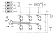
- FIG. 1 is an overall configuration diagram of a control system for a rotating electrical machine according to a first embodiment
- FIG. 2 is a diagram showing an inverter and its peripheral configuration.
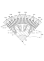
- FIG. 3 is a cross-sectional view of the rotor and the stator;
- FIG. 4 is a diagram showing an electric circuit provided in the rotor;
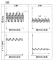
- FIG. 5 is a time chart showing changes in current and torque flowing through the first and second windings;
- FIG. 6 is a diagram showing an electric circuit provided in a rotor according to a comparative example;
- FIG. 7 is a time chart showing changes in current and torque flowing through the first and second windings according to a comparative example
- FIG. 8 is a diagram showing an electric circuit provided in a rotor according to a second embodiment
- FIG. 9 is a time chart showing changes in current and torque flowing through the first and second windings
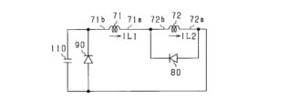
- FIG. 10 is a diagram showing an electric circuit provided in a rotor according to a third embodiment
- FIG. 11 is a time chart showing changes in current and torque flowing through the first and second windings
- FIG. 12 is a diagram showing an electric circuit provided in a rotor according to a fourth embodiment
- FIG. 13 is a time chart showing changes in current and torque flowing through the first and second windings
- FIG. 14 is a diagram showing an electric circuit provided in a rotor according to a fifth embodiment
- FIG. 15 is a time chart showing changes in current and torque flowing through the first and second windings
- FIG. 16 is a diagram showing an electric circuit provided in a rotor according to another embodiment
- FIG. 17 is a diagram showing an electric circuit provided in a rotor according to another embodiment
- FIG. 18 is a diagram showing an electric circuit provided in a rotor according to another embodiment
- FIG. 19 is a diagram showing an electric circuit of a rotor according to another embodiment
- FIG. 20 is a diagram showing an electric circuit provided in a rotor according to another embodiment
- FIG. 21 is a diagram showing an electric circuit provided in a rotor according to another embodiment
- FIG. 22 is a diagram showing an electric circuit provided in a rotor according to another embodiment
- FIG. 23 is a diagram showing an electric circuit provided in a rotor according to another embodiment
- FIG. 24 is a diagram showing an electric circuit provided in a rotor according to another embodiment
- FIG. 25 is a diagram showing an electric circuit provided in a rotor according to another embodiment
- FIG. 26 is a diagram showing an electric circuit provided in a rotor according to another embodiment
- FIG. 27 is a diagram showing an electric circuit provided in a rotor according to another embodiment
- FIG. 28 is a diagram showing an electric circuit provided in a rotor according to another embodiment
- FIG. 29 is a diagram showing an electric circuit provided in a rotor according to another embodiment
- FIG. 29 is a diagram showing an electric circuit provided in a rotor according to another embodiment
- FIG. 30 is a diagram showing an electric circuit provided in a rotor according to another embodiment
- FIG. 31 is a diagram showing an electric circuit provided in a rotor according to another embodiment
- FIG. 32 is a diagram showing an electric circuit provided in a rotor according to another embodiment
- FIG. 33 is a diagram showing an electric circuit provided in a rotor according to another embodiment
- FIG. 34 is a diagram showing an electric circuit of a rotor according to another embodiment
- FIG. 35 is a cross-sectional view of a rotor and a stator according to another embodiment.
- the rotating electric machine constitutes a control system for the rotating electric machine, and the control system is mounted on a vehicle.
- the rotating electric machine is a power source for driving the vehicle.
- the control system includes a DC power supply 10, an inverter 20, a control device 30, and a rotating electric machine 40.
- the rotating electric machine 40 is a self-excited field winding type synchronous machine.
- the rotating electric machine 40, the inverter 20, and the control device 30 may be included to form an integrated mechanical and electrical drive device, or the rotating electric machine 40, the inverter 20, and the control device 30 may each be composed of individual components.
- the rotating electric machine 40 includes a housing 41, and a stator 50 and a rotor 60 housed within the housing 41.
- the rotating electric machine 40 of this embodiment is an inner rotor type rotating electric machine in which the rotor 60 is disposed radially inside the stator 50.
- the rotor 60 includes a rotor core 61 and a field winding 70.
- the field winding 70 is made of, for example, aluminum wire, copper wire, or CNT (carbon nanotube).
- a rotating shaft 32 is inserted through the central hole of the rotor core 61.
- the rotating shaft 32 is rotatably supported by the housing 41 via a bearing 42.
- the inverter 20 includes a series connection of U-, V-, and W-phase upper-arm switches SUp, SVp, and SWp and U-, V-, and W-phase lower-arm switches SUn, SVn, and SWn.
- First ends of the U-, V-, and W-phase windings 52U, 52V, and 52W are connected to the connection points between the U-, V-, and W-phase upper-arm switches SUp, SVp, and SWp and the U-, V-, and W-phase lower-arm switches SUn, SVn, and SWn.
- Second ends of the U-, V-, and W-phase windings 52U, 52V, and 52W are connected at the neutral point.
- each switch SUp to SWn is an IGBT.
- a freewheel diode is connected in inverse parallel to each switch SUp to SWn.
- Each switch SUp to SWn may be, for example, an N-channel MOSFET.
- the positive terminal of the DC power supply 10 is connected to the collectors, which are the high-potential terminals of the U-, V-, and W-phase upper arm switches SUp, SVp, and SWp.
- the negative terminal of the DC power supply 10 is connected to the emitters, which are the low-potential terminals of the U-, V-, and W-phase lower arm switches SUn, SVn, and SWn.
- a smoothing capacitor 11 is connected in parallel to the DC power supply 10.
- stator 50 and rotor 60 will be described using FIG. 3.
- the stator 50 is made of laminated steel plates made of soft magnetic material, and has an annular back yoke 51a and a number of teeth 51b that protrude radially inward from the back yoke 51a.
- a number of slots 54 are formed between adjacent teeth 51b and aligned in the circumferential direction.
- the stator winding 52 is formed by accommodating the phase windings of each phase in each slot 54 in a predetermined order.
- the rotor 60 is made of a soft magnetic material, for example laminated steel plates.
- the rotor 60 has a cylindrical rotor core 61 and a number of main poles 62 that protrude radially outward from the rotor core 61. In this embodiment, eight main poles 62 are provided at equal intervals in the circumferential direction.
- the field winding 70 includes a first winding portion 71 and a second winding portion 72.
- the first winding portion 71 is wound radially outward
- the second winding portion 72 is wound radially inward from the first winding portion 71.
- the winding directions of the first winding portion 71 and the second winding portion 72 are the same.
- the winding direction of each winding portion 71, 72 wound around one is opposite to the winding direction of each winding portion 71, 72 wound around the other. Therefore, the magnetization directions of the main pole portions 62 adjacent in the circumferential direction are opposite to each other.
- the control system includes a current sensor 21, an angle sensor 22, a voltage sensor 23, and a temperature sensor 24.
- the current sensor 21 detects at least two phases of the currents flowing through the rotating electric machine 40.
- the angle sensor 22 detects the rotation angle (electrical angle) of the rotor 60, and is, for example, a resolver.
- the voltage sensor 23 detects the voltage of the DC power supply 10.
- the temperature sensor 24 detects the temperature of the rotating electric machine, etc., and is, for example, a thermistor.
- the detection values of the sensors 21 to 24 are input to the control device 30.
- the control device 30 is an electronic control unit mainly composed of a microcomputer 31.
- the microcomputer 31 has a CPU (Central Processing Unit).
- the functions provided by the microcomputer 31 can be provided by software recorded in a physical memory device and a computer that executes the software, by software alone, by hardware alone, or by a combination of these.
- the microcomputer 31 when the microcomputer 31 is provided by an electronic circuit that is hardware, it can be provided by a digital circuit including a large number of logic circuits, or by an analog circuit.
- the microcomputer 31 executes a program stored in a non-transitory tangible storage medium that serves as a storage unit provided in the microcomputer 31.
- the program includes a program for control processing of the rotating electric machine 40.
- a method corresponding to the program is executed by executing a set of instructions that constitute the program.
- the storage unit is, for example, a non-volatile memory.
- the program stored in the storage unit can be updated via a communication network such as the Internet, for example, OTA (Over The Air).
- FIG. 4 is a diagram showing the electrical circuit on the rotor 60 side, which has first and second winding sections 71, 72.
- the first winding section 71 shown in FIG. 4 is a series connection of first winding sections 71 wound around each main pole section 62
- the second winding section 72 shown in FIG. 4 is a series connection of second winding sections 72 wound around each main pole section 62.
- the rotor 60 includes a parallel diode 80 (corresponding to an "electrical path") and a series capacitor 100.
- the parallel diode 80 is connected in parallel to the second winding section 72. More specifically, the anode of the parallel diode 80 is connected to the first end 72a of the second winding section 72, and the cathode of the parallel diode 80 is connected to the second end 72b of the second winding section 72.
- the second end 72b of the second winding portion 72 is connected to the first end 71a of the first winding portion 71.
- the second end 71b of the first winding portion 71 is connected to the first end 72a of the second winding portion 72 via the series capacitor 100.
- the number of turns of the second winding portion 72 is greater than the number of turns of the first winding portion 71.
- the series capacitor 100 is, for example, a ceramic capacitor or a film capacitor.
- the control device 30 generates drive signals that turn on and off each switch SUp to SWn that constitutes the inverter 20.
- the control device 30 generates drive signals that turn on and off each arm switch SUp to SWn in order to convert the DC power output from the DC power source 10 into AC power and supply it to the U-, V-, and W-phase windings 52U, 52V, and 52W, and supplies the generated drive signals to the gates of each arm switch SUp to SWn.
- the upper arm switch and the lower arm switch in each phase are alternately turned on with a dead time in between.
- the control device 30 turns on and off each switch SUp to SWn so that a composite current of a fundamental current and a high-frequency current (specifically, a high-frequency excitation current) having a higher frequency than the fundamental current flows through each phase winding 52U, 52V, 52W.
- the fundamental current is a current that mainly generates torque in the rotating electric machine 40.
- the high-frequency current is a current that mainly excites the first and second winding parts 71 and 72 that make up the field winding 70, thereby inducing a field current in the field winding 70.
- the phase currents flowing through each phase winding 52U, 52V, 52W are shifted by 120° in electrical angle.
- the high-frequency current passed through the stator winding 52 may be a harmonic current whose fluctuating frequency is N times (N is an integer equal to or greater than 2) the frequency of the fundamental current, or a current whose fluctuating frequency is different from N times the frequency of the fundamental current.
- FIG. 4 shows the current IL1 flowing through the first winding section 71, the current IL2 flowing through the second winding section 72, and the torque of the rotating electric machine 40 during one electrical angle period of the rotor 60 when the rotation speed of the rotor 60 is 3000 rpm and the excitation frequency (specifically, the frequency of the high-frequency current) is 2.4 kHz.
- the current IL1 flowing through the first winding section 71 is positive in the direction from the second end 71b side to the first end 71a side of the first winding section 71.
- the current IL2 flowing through the second winding section 72 is positive in the direction from the second end 72b side to the first end 72a side of the second winding section 72.
- the stator winding 52 When a high-frequency current flows through the stator winding 52, a voltage is induced in the first and second winding sections 71 and 72, causing a field current to flow.
- the induced voltages in the first and second winding sections 71 and 72 are, for example, in phase.
- the currents IL1 and IL2 flowing through the first and second winding sections 71 and 72 contain frequency components of the high-frequency current.
- a current I1 flows from the first winding portion 71 to the second winding portion 72.
- a current I2a flows through the closed circuit including the second winding section 72 and the parallel diode 80. Note that a current flows through the closed circuit when the voltage across the second winding section 72 exceeds the forward voltage Vf of the parallel diode 80.
- the DC component of the field current can be increased.
- the DC component of the magnetic flux of the rotor 60 can be increased, and the torque of the rotating electric machine 40 can be increased.
- the sign of the change in the current IL1 flowing in the first winding portion 71 i.e., the increase or decrease in the current IL1
- the sign of the change in the current IL2 flowing in the second winding portion 72 i.e., the increase or decrease in the current IL2.
- Figure 6 shows the rotor side electric circuit in the comparative example.
- This electric circuit includes a diode 74, a first capacitor 74, and a second capacitor 75.
- Figure 7 shows the transition of the current IL1 flowing through the first winding section 71, the current IL2 flowing through the second winding section 72, and the torque of the rotating electric machine over one period of the rotor electrical angle when the rotor rotation speed is 3000 rpm and the excitation frequency is 2.4 kHz.
- One scale mark on the vertical axis of current and torque in Figure 7 is the same size as one scale mark on the vertical axis of current and torque in Figure 5 above.
- the DC component of the field current is increased mainly by charging and discharging the first capacitor 74.
- the left column of Figure 7 shows a time chart in which the capacitance of the first capacitor 74 is set so that the torque of the rotating electric machine in the comparative example is equivalent to the torque of this embodiment.
- the capacitance of the first capacitor 74 in the comparative example is larger than the capacitance of the series capacitor 100 in this embodiment, and more specifically, is about three times the capacitance of the series capacitor 100, for example.
- the first capacitor 74 in the comparative example is larger than the series capacitor 100 in this embodiment.
- a series diode 90 (corresponding to a "regulating portion") is provided on the rotor 60 instead of the series capacitor 100.
- the anode of the series diode 90 is connected to the first end 72a of the second winding portion 72.
- the cathode of the series diode 90 is connected to the second end 71b of the first winding portion 71. This forms a closed circuit including the first winding portion 71, the second winding portion 72, and the series diode 90.
- the anodes of the parallel diode 80 and the series diode 90 are electrically connected to each other.
- Figure 9 shows the changes in the current IL1 flowing through the first winding section 71, the current IL2 flowing through the second winding section 72, and the torque of the rotating electric machine 40 over one electrical angle period of the rotor 60 when the rotational speed of the rotor 60 is 3000 rpm and the excitation frequency is 2.4 kHz.
- One graduation on the vertical axis of the current and torque in Figure 9 is the same size as one graduation on the vertical axis of the current and torque in Figure 5 above.
- the series diode 90 prevents current from flowing in the direction from the first end 71a to the second end 71b in the first winding portion 71. This rectifies the current IL1 flowing in the first winding portion 71, reducing the pulsation of the current IL1 flowing in the first winding portion 71. The rectification of the current IL1 flowing in the first winding portion 71 changes the current IL2 flowing in the second winding portion 72. The effect of rectification described above reduces the pulsation of the field current, and ultimately reduces the torque pulsation of the rotating electric machine 40.
- a series diode 90 is connected in series to the first winding section 71, which has stronger magnetic coupling with the stator winding 52, of the first and second winding sections 71, 72, and a parallel diode 80 is connected in parallel to the second winding section 72, which has weaker magnetic coupling. Since the effect of the voltage induced in the winding section with weaker magnetic coupling is smaller than that of the winding section with stronger magnetic coupling, the parallel diode 80 is connected in parallel to the second winding section 72, which has weaker magnetic coupling, thereby further enhancing the effect of reducing pulsation of the field current and the effect of increasing the DC component.
- the second winding section 72 which is farther away from the stator winding 52 in the radial direction, of the first and second winding sections 71, 72, has weaker magnetic coupling than the first winding section 71.
- the second winding section 72 which has weaker magnetic coupling with the stator winding 52, has a greater number of turns than the first winding section 71, which has stronger magnetic coupling.
- the effect of reducing field current pulsation and increasing the DC component can be further improved, and the effect of reducing current pulsation, the effect of reducing torque pulsation due to the increase in the DC component, and the effect of increasing torque can be improved.
- Reducing current pulsation also contributes to improving efficiency.
- the electrical load on the diodes 80, 90 is also reduced.
- the parallel diode 80 and the series diode 90 may be arranged in the opposite directions. More specifically, the cathode of the parallel diode 80 is connected to the first end 72a of the second winding portion 72, and the anode of the parallel diode 80 is connected to the second end 72b of the second winding portion 72. The cathode of the series diode 90 is connected to the first end 72a of the second winding portion 72, and the anode of the series diode 90 is connected to the second end 71b of the first winding portion 71. In this case, the cathodes of the parallel diode 80 and the series diode 90 are electrically connected to each other.
- the parallel diode 80 and the series diode 90 are not limited to diodes as long as they are elements that allow current to flow in one direction.
- elements that have a first terminal and a second terminal, allow current to flow from the first terminal to the second terminal, and prevent current from flowing from the second terminal to the first terminal may be used as the parallel diode 80 and the series diode 90.
- the parallel diode 80 and the series diode 90 may be elements that can prevent current from flowing in the reverse direction, such as a body diode of a MOSFET (e.g., an N-channel MOSFET).
- the control device 30 may perform synchronous rectification by turning the MOSFET on and off.
- the MOSFET may be turned on and off by a circuit built into the rotor 60, or by wireless communication via a transformer or the like.
- a parallel capacitor 110 connected in parallel to a series diode 90 is provided on a rotor 60.
- a first end of the parallel capacitor 110 is connected to a second end 71b of the first winding portion 71, and a second end of the parallel capacitor 110 is connected to a first end 72a of the second winding portion 72.
- the capacitance of the parallel capacitor 110 is smaller than the capacitance of the series capacitor 100 shown in FIG. 4 above, and specifically, for example, is 1 ⁇ 2 or less, 1 ⁇ 3 or less, or 1 ⁇ 4 or less of the capacitance of the series capacitor 100.
- the parallel capacitor 110 is, for example, a ceramic capacitor or a film capacitor.
- Figure 11 shows the changes in the current IL1 flowing through the first winding section 71, the current IL2 flowing through the second winding section 72, and the torque of the rotating electric machine 40 over one electrical angle period of the rotor 60 when the rotational speed of the rotor 60 is 3000 rpm and the excitation frequency is 2.4 kHz.
- One graduation on the vertical axis of the current and torque in Figure 11 is the same size as one graduation on the vertical axis of the current and torque in Figure 9 above.
- the parallel capacitor 110 By providing the parallel capacitor 110, the impedance of the closed circuit including the parallel capacitor 110 is reduced, making it easier for a current to flow through this closed circuit. This increases the DC component of the field current.
- the parallel capacitor 110 reduces the change in the current IL1 flowing through the first winding section 71 and the current IL2 flowing through the second winding section 72, making the current waveform smoother and changing the phase of the current waveform. As the current waveform becomes smoother and the phase of the current waveform changes, the pulsation of the field current is reduced and the pulsation of the torque determined by the sum of the two winding sections 71 and 72 is reduced. The reduction in current pulsation also contributes to improved efficiency.
- the electrical load on the diodes 80 and 90 is reduced. Compared to the comparative example described in the first embodiment, the electrical load on the parallel capacitor 110 is also reduced in this embodiment.
- a capacitor 120 connected in parallel to the second winding portion 72 is provided on the rotor 60.
- the capacitor 120 is referred to as the winding-side capacitor 120.
- the capacitance of the winding-side capacitor 120 is equal to the capacitance of the series capacitor 100.
- the winding-side capacitor 120 is, for example, a ceramic capacitor or a film capacitor.
- Figure 13 shows the changes in the current IL1 flowing through the first winding section 71, the current IL2 flowing through the second winding section 72, and the torque of the rotating electric machine 40 over one electrical angle period of the rotor 60 when the rotational speed of the rotor 60 is 3000 rpm and the excitation frequency is 2.4 kHz.
- One graduation on the vertical axis of the current and torque in Figure 13 is the same size as one graduation on the vertical axis of the current and torque in Figure 11.
- the winding-side capacitor 120 By providing the winding-side capacitor 120, it is possible to individually set the impedance of the closed circuit formed by the first and second winding portions 71, 72, and to shift the phase of the current pulsation, thereby reducing the pulsation of the field current. As a result, it is possible to reduce the torque pulsation of the rotating electric machine 40. Furthermore, arranging the winding-side capacitor 120 in the vicinity of the parallel diode 80 also leads to a reduction in the electrical load on the diodes 80, 90. Compared to the comparative example described in the first embodiment, the electrical load on the parallel capacitor 110 is also reduced in this embodiment. ⁇ Fifth embodiment> The fifth embodiment will be described below with reference to the drawings, focusing on the differences from the fourth embodiment.
- a capacitor 121 is provided in the rotor 60 instead of the parallel capacitor 110.
- the capacitor 121 is referred to as the first winding side capacitor 121
- the winding side capacitor 120 is referred to as the second winding side capacitor 120.
- the first winding side capacitor 121 is connected in parallel to the first winding portion 71.
- the first winding side capacitor 121 is, for example, a ceramic capacitor or a film capacitor.
- Figure 15 shows the changes in the current IL1 flowing through the first winding section 71, the current IL2 flowing through the second winding section 72, and the torque of the rotating electric machine 40 over one electrical angle period of the rotor 60 when the rotational speed of the rotor 60 is 3000 rpm and the excitation frequency is 2.4 kHz.
- One graduation on the vertical axis of the current and torque in Figure 15 is the same size as one graduation on the vertical axis of the current and torque in Figure 13 above.
- the impedance of the closed circuit formed by the first and second winding sections 71 and 72 can be set individually, and the phase of the current pulsation can be shifted, thereby reducing the pulsation of the field current.
- the torque pulsation of the rotating electric machine 40 can be reduced.
- the parallel capacitor 110 shown in the fourth embodiment is applied with a voltage obtained by adding up the voltage of the first winding section 71 and the voltage of the second winding section 72, whereas the first winding side capacitor 121 in this embodiment is applied with only the voltage of the first winding section 71, thereby reducing the load on the first winding side capacitor 121.
- arranging the capacitors 120 and 121 near the parallel diode 80 and the series diode 90 also reduces the electrical load on the diodes 80 and 90.
- the circuit shown in FIG. 16 is the same as the circuit shown in FIG. 12, except that a capacitor 121 is connected in parallel to the first winding portion 71.
- the circuit shown in FIG. 17 is the same as the circuit shown in FIG. 12 above, except that a capacitor 121 is connected in parallel to the first winding section 71 instead of the second winding section 72.
- the circuit shown in FIG. 18 is the same as the circuit shown in FIG. 8, except that a capacitor 120 is connected in parallel to the second winding portion 72.
- the circuit shown in FIG. 19 is the same as the circuit shown in FIG. 8, except that a capacitor 121 is connected in parallel to the first winding portion 71.
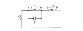
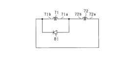
- the circuit shown in FIG. 20 is a circuit in which a parallel diode 81 is connected in parallel to the first winding section 71 instead of the second winding section 72 in the circuit shown in FIG. 4 above.
- the anode of the parallel diode 81 is connected to the first end 71a of the first winding section 71, and the cathode of the parallel diode 81 is connected to the second end 71b of the first winding section 71.
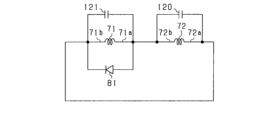
- the circuit shown in FIG. 21 is the same as the circuit shown in FIG. 20, except that a capacitor 121 is connected in parallel to the first winding portion 71.
- the circuit shown in FIG. 22 is the same as the circuit shown in FIG. 21, except that a capacitor 120 is connected in parallel to the second winding portion 72.
- the circuit shown in FIG. 23 is the same as the circuit shown in FIG. 4, except that a parallel diode 81 is connected in parallel to the first winding portion 71.
- the circuit shown in FIG. 24 is the same as the circuit shown in FIG. 23, except that a capacitor 121 is connected in parallel to the first winding portion 71. Note that in the circuit of FIG. 24, a capacitor may be connected in parallel to the second winding portion 72 instead of the first winding portion 71.
- the circuit shown in FIG. 25 is the same as the circuit shown in FIG. 24, except that a capacitor 120 is connected in parallel to the second winding portion 72.
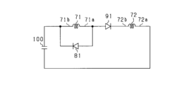
- the circuit shown in FIG. 26 is the same as the circuit shown in FIG. 20, except that the first end 71a of the first winding portion 71 and the second end 72b of the second winding portion 72 are connected by a series diode 91.
- the anode of the series diode 91 is connected to the first end 71a of the first winding portion 71, and the cathode of the series diode 91 is connected to the second end 72b of the second winding portion 72.
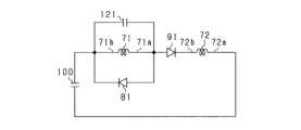
- the circuit shown in FIG. 27 is the same as the circuit shown in FIG. 26, except that a capacitor 121 is connected in parallel to the first winding portion 71. Note that in the circuit of FIG. 27, a capacitor may be connected in parallel to the second winding portion 72 instead of the first winding portion 71.
- the circuit shown in FIG. 28 is the same as the circuit shown in FIG. 27, except that a capacitor 120 is connected in parallel to the second winding portion 72.
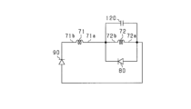
- the circuit shown in FIG. 29 is a circuit in which a series diode 91 is provided between the first end 71a of the first winding portion 71 and the second end 72b of the second winding portion 72, instead of between the second end 71b of the first winding portion 71 and the first end 72a of the second winding portion 72 in the circuit shown in FIG. 8 above.
- the circuit shown in FIG. 30 is the same as the circuit shown in FIG. 29, except that a capacitor 121 is connected in parallel to the first winding section 71, and a capacitor 120 is connected in parallel to the second winding section 72. Note that either of the capacitors 120 and 121 may not be provided in the circuit shown in FIG. 30.
- the orientation of the diodes 81, 91 may be reversed.
- the cathode of the parallel diode 81 is connected to the first end 71a of the first winding section 71, and the anode of the parallel diode 81 is connected to the second end 71b of the first winding section 71.
- the cathode of the series diode 91 is connected to the first end 71a of the first winding section 71, and the anode of the series diode 91 is connected to the second end 71b of the first winding section 71.
- the series capacitor 100 does not have to be provided.
- the second end 71b of the first winding portion 71 and the first end 72a of the second winding portion 72 are connected.
- a parallel diode 81 may be connected in parallel to the first winding portion 71 instead of the second winding portion 72.
- the circuit shown in FIG. 32 is the same as the circuit shown in FIG. 31, except that a capacitor 121 is connected in parallel to the first winding section 71, and a capacitor 120 is connected in parallel to the second winding section 72.
- the circuit shown in FIG. 33 is the same as the circuit shown in FIG. 31, except that a parallel diode 80 is connected in parallel to the second winding portion 72.
- the circuit shown in FIG. 34 is the same as the circuit shown in FIG. 33, except that a capacitor 121 is connected in parallel to the first winding section 71, and a capacitor 120 is connected in parallel to the second winding section 72.
- the number of turns of the second winding section 72 may be less than the number of turns of the first winding section 71, or may be the same as the number of turns of the first winding section 71.
- the rotating electric machine is not limited to an inner rotor type rotating electric machine, but may be an outer rotor type rotating electric machine.
- the main pole portion protrudes radially inward from the rotor core.
- the rotating electric machine is not limited to a star-connected rotating electric machine, but may also be a delta-connected rotating electric machine.
- the stator core may be a stator core that does not have teeth.
- the rotating electric machine is not limited to a rotating electric machine used as an in-vehicle main engine, but may be, for example, a rotating electric machine used as an ISG (Integrated Starter Generator) that is both a motor and generator, or a rotating electric machine for auxiliary machinery.
- ISG Integrated Starter Generator
- the moving body on which the control system is mounted is not limited to a vehicle, but may be, for example, an aircraft or a ship. Furthermore, the control system is not limited to a system mounted on a moving body, but may be a stationary system.
- a stator having stator windings (52); A rotor (60) facing the stator in the radial direction;
- a rotating electric machine comprising: The rotor is A main pole portion (62) is provided for each of the magnetic poles arranged in the circumferential direction and protrudes in the radial direction; A field winding (70) wound around each of the main pole portions; having The field winding has a first winding portion (71) and a second winding portion (72), an electrical path (80, 81) connected in parallel to at least one of the first winding portion and the second winding portion; The rotating electric machine, wherein the electric path is configured to allow a current to flow therethrough in one direction.
- a regulating section (90, 91) connected in series to one of the first winding section and the second winding section to which the electrical path is not connected in parallel, and causing a current to flow in one direction.
- the electrical path includes a parallel diode that is a diode connected in parallel to at least one of the first winding portion and the second winding portion.
- the regulating portion includes a series diode connected in series to one of the first winding portion and the second winding portion.
Landscapes
- Engineering & Computer Science (AREA)
- Power Engineering (AREA)
- Synchronous Machinery (AREA)
Priority Applications (1)
| Application Number | Priority Date | Filing Date | Title |
|---|---|---|---|
| CN202480061660.2A CN121925776A (zh) | 2023-09-28 | 2024-09-02 | 旋转电机 |
Applications Claiming Priority (2)
| Application Number | Priority Date | Filing Date | Title |
|---|---|---|---|
| JP2023-168361 | 2023-09-28 | ||
| JP2023168361A JP2025058439A (ja) | 2023-09-28 | 2023-09-28 | 回転電機 |
Publications (1)
| Publication Number | Publication Date |
|---|---|
| WO2025069942A1 true WO2025069942A1 (ja) | 2025-04-03 |
Family
ID=95203820
Family Applications (1)
| Application Number | Title | Priority Date | Filing Date |
|---|---|---|---|
| PCT/JP2024/031467 Pending WO2025069942A1 (ja) | 2023-09-28 | 2024-09-02 | 回転電機 |
Country Status (3)
| Country | Link |
|---|---|
| JP (1) | JP2025058439A (https=) |
| CN (1) | CN121925776A (https=) |
| WO (1) | WO2025069942A1 (https=) |
Citations (3)
| Publication number | Priority date | Publication date | Assignee | Title |
|---|---|---|---|---|
| JP2016067128A (ja) * | 2014-09-25 | 2016-04-28 | Ntn株式会社 | 発電機 |
| JP2018042401A (ja) * | 2016-09-08 | 2018-03-15 | 株式会社デンソー | 界磁巻線式回転機 |
| WO2022196285A1 (ja) * | 2021-03-18 | 2022-09-22 | 株式会社デンソー | 界磁巻線型回転電機 |
-
2023
- 2023-09-28 JP JP2023168361A patent/JP2025058439A/ja active Pending
-
2024
- 2024-09-02 WO PCT/JP2024/031467 patent/WO2025069942A1/ja active Pending
- 2024-09-02 CN CN202480061660.2A patent/CN121925776A/zh active Pending
Patent Citations (3)
| Publication number | Priority date | Publication date | Assignee | Title |
|---|---|---|---|---|
| JP2016067128A (ja) * | 2014-09-25 | 2016-04-28 | Ntn株式会社 | 発電機 |
| JP2018042401A (ja) * | 2016-09-08 | 2018-03-15 | 株式会社デンソー | 界磁巻線式回転機 |
| WO2022196285A1 (ja) * | 2021-03-18 | 2022-09-22 | 株式会社デンソー | 界磁巻線型回転電機 |
Also Published As
| Publication number | Publication date |
|---|---|
| JP2025058439A (ja) | 2025-04-09 |
| CN121925776A (zh) | 2026-04-24 |
Similar Documents
| Publication | Publication Date | Title |
|---|---|---|
| JP7501784B2 (ja) | 界磁巻線型回転電機 | |
| CN111987832B (zh) | 励磁线圈型旋转电机 | |
| JP2020124100A (ja) | 界磁巻線型回転電機 | |
| CN112753156B (zh) | 励磁绕组型旋转电机 | |
| CN111712999B (zh) | 励磁绕组型旋转电机 | |
| WO2020066482A1 (ja) | 界磁巻線型回転電機 | |
| WO2025069942A1 (ja) | 回転電機 | |
| CN119013887A (zh) | 旋转电机的控制装置 | |
| US20260106563A1 (en) | Motor control device and storage medium | |
| WO2025220399A1 (ja) | 巻線界磁型回転電機 | |
| EP4604366A1 (en) | Winding field rotor | |
| JP2025030920A (ja) | 回転電機の制御装置、制御プログラム | |
| WO2025220400A1 (ja) | 巻線界磁ロータ | |
| WO2025154564A1 (ja) | 巻線界磁型回転電機 | |
| WO2025154563A1 (ja) | 巻線界磁型回転電機 | |
| WO2025216021A1 (ja) | 巻線界磁ロータ | |
| JP2026068546A (ja) | システム | |
| WO2025018153A1 (ja) | 巻線界磁型回転電機 | |
| WO2025018154A1 (ja) | 巻線界磁型回転電機 | |
| WO2026063144A1 (ja) | 回転電機、システム | |
| WO2025211085A1 (ja) | 巻線界磁ロータ | |
| WO2024262236A1 (ja) | 回転電機 | |
| WO2024053459A1 (ja) | 回転電機の制御装置、及びプログラム |
Legal Events
| Date | Code | Title | Description |
|---|---|---|---|
| 121 | Ep: the epo has been informed by wipo that ep was designated in this application |
Ref document number: 24871742 Country of ref document: EP Kind code of ref document: A1 |