WO2025069872A1 - 電極、および非水電解質二次電池 - Google Patents
電極、および非水電解質二次電池 Download PDFInfo
- Publication number
- WO2025069872A1 WO2025069872A1 PCT/JP2024/030614 JP2024030614W WO2025069872A1 WO 2025069872 A1 WO2025069872 A1 WO 2025069872A1 JP 2024030614 W JP2024030614 W JP 2024030614W WO 2025069872 A1 WO2025069872 A1 WO 2025069872A1
- Authority
- WO
- WIPO (PCT)
- Prior art keywords
- electrode
- active material
- composite sheet
- positive electrode
- less
- Prior art date
- Legal status (The legal status is an assumption and is not a legal conclusion. Google has not performed a legal analysis and makes no representation as to the accuracy of the status listed.)
- Ceased
Links
Images

Classifications
-
- H—ELECTRICITY
- H01—ELECTRIC ELEMENTS
- H01G—CAPACITORS; CAPACITORS, RECTIFIERS, DETECTORS, SWITCHING DEVICES, LIGHT-SENSITIVE OR TEMPERATURE-SENSITIVE DEVICES OF THE ELECTROLYTIC TYPE
- H01G11/00—Hybrid capacitors, i.e. capacitors having different positive and negative electrodes; Electric double-layer [EDL] capacitors; Processes for the manufacture thereof or of parts thereof
- H01G11/22—Electrodes
- H01G11/30—Electrodes characterised by their material
- H01G11/32—Carbon-based
- H01G11/38—Carbon pastes or blends; Binders or additives therein
-
- H—ELECTRICITY
- H01—ELECTRIC ELEMENTS
- H01G—CAPACITORS; CAPACITORS, RECTIFIERS, DETECTORS, SWITCHING DEVICES, LIGHT-SENSITIVE OR TEMPERATURE-SENSITIVE DEVICES OF THE ELECTROLYTIC TYPE
- H01G11/00—Hybrid capacitors, i.e. capacitors having different positive and negative electrodes; Electric double-layer [EDL] capacitors; Processes for the manufacture thereof or of parts thereof
- H01G11/22—Electrodes
- H01G11/26—Electrodes characterised by their structure, e.g. multi-layered, porosity or surface features
- H01G11/28—Electrodes characterised by their structure, e.g. multi-layered, porosity or surface features arranged or disposed on a current collector; Layers or phases between electrodes and current collectors, e.g. adhesives
-
- H—ELECTRICITY
- H01—ELECTRIC ELEMENTS
- H01G—CAPACITORS; CAPACITORS, RECTIFIERS, DETECTORS, SWITCHING DEVICES, LIGHT-SENSITIVE OR TEMPERATURE-SENSITIVE DEVICES OF THE ELECTROLYTIC TYPE
- H01G11/00—Hybrid capacitors, i.e. capacitors having different positive and negative electrodes; Electric double-layer [EDL] capacitors; Processes for the manufacture thereof or of parts thereof
- H01G11/22—Electrodes
- H01G11/30—Electrodes characterised by their material
- H01G11/32—Carbon-based
- H01G11/40—Fibres
-
- H—ELECTRICITY
- H01—ELECTRIC ELEMENTS
- H01G—CAPACITORS; CAPACITORS, RECTIFIERS, DETECTORS, SWITCHING DEVICES, LIGHT-SENSITIVE OR TEMPERATURE-SENSITIVE DEVICES OF THE ELECTROLYTIC TYPE
- H01G11/00—Hybrid capacitors, i.e. capacitors having different positive and negative electrodes; Electric double-layer [EDL] capacitors; Processes for the manufacture thereof or of parts thereof
- H01G11/22—Electrodes
- H01G11/30—Electrodes characterised by their material
- H01G11/32—Carbon-based
- H01G11/42—Powders or particles, e.g. composition thereof
-
- H—ELECTRICITY
- H01—ELECTRIC ELEMENTS
- H01G—CAPACITORS; CAPACITORS, RECTIFIERS, DETECTORS, SWITCHING DEVICES, LIGHT-SENSITIVE OR TEMPERATURE-SENSITIVE DEVICES OF THE ELECTROLYTIC TYPE
- H01G11/00—Hybrid capacitors, i.e. capacitors having different positive and negative electrodes; Electric double-layer [EDL] capacitors; Processes for the manufacture thereof or of parts thereof
- H01G11/22—Electrodes
- H01G11/30—Electrodes characterised by their material
- H01G11/32—Carbon-based
- H01G11/44—Raw materials therefor, e.g. resins or coal
-
- H—ELECTRICITY
- H01—ELECTRIC ELEMENTS
- H01G—CAPACITORS; CAPACITORS, RECTIFIERS, DETECTORS, SWITCHING DEVICES, LIGHT-SENSITIVE OR TEMPERATURE-SENSITIVE DEVICES OF THE ELECTROLYTIC TYPE
- H01G11/00—Hybrid capacitors, i.e. capacitors having different positive and negative electrodes; Electric double-layer [EDL] capacitors; Processes for the manufacture thereof or of parts thereof
- H01G11/66—Current collectors
- H01G11/68—Current collectors characterised by their material
-
- H—ELECTRICITY
- H01—ELECTRIC ELEMENTS
- H01G—CAPACITORS; CAPACITORS, RECTIFIERS, DETECTORS, SWITCHING DEVICES, LIGHT-SENSITIVE OR TEMPERATURE-SENSITIVE DEVICES OF THE ELECTROLYTIC TYPE
- H01G11/00—Hybrid capacitors, i.e. capacitors having different positive and negative electrodes; Electric double-layer [EDL] capacitors; Processes for the manufacture thereof or of parts thereof
- H01G11/84—Processes for the manufacture of hybrid or EDL capacitors, or components thereof
- H01G11/86—Processes for the manufacture of hybrid or EDL capacitors, or components thereof specially adapted for electrodes
-
- H—ELECTRICITY
- H01—ELECTRIC ELEMENTS
- H01M—PROCESSES OR MEANS, e.g. BATTERIES, FOR THE DIRECT CONVERSION OF CHEMICAL ENERGY INTO ELECTRICAL ENERGY
- H01M4/00—Electrodes
- H01M4/02—Electrodes composed of, or comprising, active material
- H01M4/13—Electrodes for accumulators with non-aqueous electrolyte, e.g. for lithium-accumulators; Processes of manufacture thereof
-
- H—ELECTRICITY
- H01—ELECTRIC ELEMENTS
- H01M—PROCESSES OR MEANS, e.g. BATTERIES, FOR THE DIRECT CONVERSION OF CHEMICAL ENERGY INTO ELECTRICAL ENERGY
- H01M4/00—Electrodes
- H01M4/02—Electrodes composed of, or comprising, active material
- H01M4/36—Selection of substances as active materials, active masses, active liquids
-
- H—ELECTRICITY
- H01—ELECTRIC ELEMENTS
- H01M—PROCESSES OR MEANS, e.g. BATTERIES, FOR THE DIRECT CONVERSION OF CHEMICAL ENERGY INTO ELECTRICAL ENERGY
- H01M4/00—Electrodes
- H01M4/02—Electrodes composed of, or comprising, active material
- H01M4/62—Selection of inactive substances as ingredients for active masses, e.g. binders, fillers
-
- Y—GENERAL TAGGING OF NEW TECHNOLOGICAL DEVELOPMENTS; GENERAL TAGGING OF CROSS-SECTIONAL TECHNOLOGIES SPANNING OVER SEVERAL SECTIONS OF THE IPC; TECHNICAL SUBJECTS COVERED BY FORMER USPC CROSS-REFERENCE ART COLLECTIONS [XRACs] AND DIGESTS
- Y02—TECHNOLOGIES OR APPLICATIONS FOR MITIGATION OR ADAPTATION AGAINST CLIMATE CHANGE
- Y02E—REDUCTION OF GREENHOUSE GAS [GHG] EMISSIONS, RELATED TO ENERGY GENERATION, TRANSMISSION OR DISTRIBUTION
- Y02E60/00—Enabling technologies; Technologies with a potential or indirect contribution to GHG emissions mitigation
- Y02E60/10—Energy storage using batteries
Definitions
- the present disclosure relates to an electrode, in particular an electrode manufactured by a dry method, and a nonaqueous electrolyte secondary battery including such an electrode.
- Electrodes for non-aqueous electrolyte secondary batteries such as lithium ion batteries are generally produced by a wet method in which an electrode composite slurry containing an active material, a binder, etc. is applied to the surface of a core material, which is a metal foil, and the coating is then dried and compressed.
- a dry method has been considered in which an electrode composite sheet is produced by stretching and forming the electrode composite into a sheet, and the sheet is then bonded to a core material to produce an electrode.
- Patent Document 1 discloses an electrode composite sheet produced by mixing an active material, a fibrillable binder such as polytetrafluoroethylene (PTFE), and a conductive material using a mill, and then applying a large shear force at high pressure to the mixture for a long period of time to fibrillate the PTFE.
- a fibrillable binder such as polytetrafluoroethylene (PTFE)
- the strength of the composite sheet may be weakened and it may not be possible to form it into a sheet. Furthermore, even if the formability is good, if the composite sheet has poor extensibility, the productivity of the electrode may decrease and the strength in the electrode thickness direction may decrease.
- the physical properties of the composite sheet vary greatly depending on the state of the fibrillated fibrous binder, but until now, it has not been clear what state the fibrous binder should be in to achieve a good quality composite sheet.
- the objective of this disclosure is to provide a composite sheet that has good formability and extensibility.
- the electrode according to the present disclosure comprises a core material and a composite sheet bonded to the surface of the core material, the composite sheet including a conductive-material-coated active material in which a conductive material is attached to the surface of the active material, and a fibrous binder, the degree of compression of the conductive-material-coated active material being 22% or less, the fibrous binder having a crystallite size of 30.5 nm or more and 35.6 nm or less, and being mainly composed of polytetrafluoroethylene.
- the nonaqueous electrolyte secondary battery according to the present disclosure includes the above-described electrodes. It is preferable that the above-described electrode configuration is applied to the positive electrode.
- a composite sheet that combines formability and extensibility can be obtained.
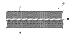
- FIG. 2 is a cross-sectional view of an electrode according to an embodiment.
- 3A to 3C are diagrams showing a process for preparing an electrode mixture and a process for preparing a mixture sheet from the electrode mixture in the manufacture of an electrode according to an embodiment of the present invention.
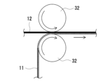
- 1A to 1C are diagrams showing a step of bonding a composite sheet to a surface of a core material in the manufacture of an electrode according to an embodiment of the present invention.
- the inventors have found that sufficient fibrillation can be achieved by compounding the active material and conductive material in advance, forming a conductive-material-coated active material in which the conductive material is attached to the surface of the active material, and then mixing it with the binder.
- the inventors further investigated and found that a composite sheet having good moldability and extensibility can be obtained by setting the compression rate of the conductive-coated active material to 22% or less, using polytetrafluoroethylene as the main component of the binder, and setting the crystallite size of the binder to 30.5 nm or more and 35.6 nm or less.
- the compression rate of the conductive-coated active material is set to 22% or less, maintaining high fluidity of the conductive-coated active material in the composite sheet, and setting the crystallite size of the polytetrafluoroethylene within the above range, the above-mentioned effects can be specifically obtained.
- the electrodes disclosed herein are suitable for non-aqueous electrolyte secondary batteries such as lithium ion batteries, but can also be applied to batteries containing aqueous electrolytes, or power storage devices such as capacitors.
- the following description will be given using an electrode for a non-aqueous electrolyte secondary battery as an example.
- the configuration and manufacturing method of the electrodes for non-aqueous electrolyte secondary batteries disclosed herein may be applied to negative electrodes, but are particularly preferably applied to positive electrodes.
- FIG. 1 is a cross-sectional view of an electrode 10, which is an example of an embodiment.
- the electrode 10 includes a core material 11 and a composite sheet 12 bonded to the surface of the core material 11.
- the composite sheet 12 is preferably bonded to both sides of the core material 11.
- the composite sheet 12 is produced by forming an electrode composite material 20 (see FIG. 2) described below into a sheet, and is bonded to the core material 11 to form an electrode composite layer.
- the electrode 10 may be a long electrode that constitutes a wound electrode body, or a rectangular electrode that constitutes a laminated electrode body.
- the core material 11 may be a metal foil or a film with a metal layer formed on its surface.
- the thickness of the core material 11 is, for example, 5 ⁇ m or more and 20 ⁇ m or less.
- the core material 11 may be a metal foil such as aluminum or an aluminum alloy.
- the core material 11 may be a metal foil such as copper or a copper alloy.
- the composite sheet 12 includes a conductive-coated active material in which a conductive material is attached to the surface of the active material, and a fibrous binder.
- the thickness of the composite sheet 12 is, for example, 50 ⁇ m or more and 150 ⁇ m or less, preferably 80 ⁇ m or more and 140 ⁇ m or less, and more preferably 100 ⁇ m or more and 130 ⁇ m or less.
- the degree of compression of the conductive-coated active material is 22% or less. This ensures that the fluidity of the conductive-coated active material in the composite sheet is at least as specified. If the degree of compression of the conductive-coated active material exceeds 22%, it is not possible to achieve both moldability and extensibility even if the crystallite size of the polytetrafluoroethylene is within the specified range described below.
- the lower limit of the degree of compression of the conductive-coated active material is not particularly limited, but is, for example, 10%.
- the compression degree of the conductive material-coated active material is calculated by the following formula:
- a Powder Tester PT-X manufactured by Hosokawa Micron Corporation can be mentioned.
- Compressibility (%) (packed bulk density - loose bulk density) / packed bulk density x 100
- the active material constituting the conductive material-coated active material may be either a positive electrode active material or a negative electrode active material.
- conductive materials constituting the conductive material-coated active material include carbon black (CB) such as acetylene black (AB) and ketjen black, graphite, carbon nanotubes (CNT), carbon nanofibers, graphene, and other carbon materials.
- CB carbon black
- the content of the conductive material in the composite sheet 12 is, for example, 0.1% by mass or more and 5% by mass or less, preferably 0.2% by mass or more and 2% by mass or less, and more preferably 0.3% by mass or more and 1% by mass or less, relative to 100 parts by mass of the active material.
- a lithium transition metal composite oxide is used as the positive electrode active material.
- Metal elements contained in the lithium transition metal composite oxide include Ni, Co, Mn, Al, B, Mg, Ti, V, Cr, Fe, Cu, Zn, Ga, Sr, Zr, Nb, In, Sn, Ta, W, etc. Among them, it is preferable to contain at least one selected from Ni, Co, and Mn.
- the content of the positive electrode active material is preferably 85% by mass or more and 99% by mass or less, and more preferably 90% by mass or more and 99% by mass or less, based on the mass of the composite sheet 12 (the suitable content of the negative electrode active material is the same as the content of the positive electrode active material).
- the positive electrode active material is a secondary particle formed by agglomeration of multiple primary particles.
- the volume-based median diameter (D50) of the positive electrode active material is preferably 3 ⁇ m or more and 30 ⁇ m or less. D50 means the particle size at which the cumulative frequency in the volume-based particle size distribution is 50% from the smallest particle size, and is also called the median diameter.
- the particle size distribution of the positive electrode active material can be measured using a laser diffraction type particle size distribution measuring device (e.g., MT3000II manufactured by Microtrack Bell) with water as the dispersion medium.
- the negative electrode active material may be, for example, a carbon-based active material such as natural graphite, such as flake graphite, lump graphite, or earthy graphite, or artificial graphite, such as lump artificial graphite (MAG) or graphitized mesophase carbon microbeads (MCMB).
- the negative electrode active material may be an active material containing Si, Sn, or the like, which is alloyed with lithium.
- the fibrous binder can be obtained, for example, by applying a predetermined shear force to a particulate binder to cause it to fibrillate.
- the fibrous binder becomes entangled with the active material particles and binds the active material particles together, making it possible to form the composite sheet 12 into a single sheet.
- the fibrous binder is preferably a material that can be fibrillated, adheres to the surfaces of the active material particles, and has chemical resistance to the electrolyte.
- the fibrous binder is mainly composed of polytetrafluoroethylene (PTFE).
- the main component means the component with the highest mass ratio, and the proportion of the main component among all the components is, for example, 90% or more.
- the fibrous binder may be substantially composed of only PTFE.
- the composite sheet 12 may contain a binder other than a fibrous binder, such as polyvinylidene fluoride (PVDF).
- PVDF polyvinylidene fluoride
- the crystallite size of the fibrous binder is 30.5 nm or more and 35.6 nm or less.
- the crystallite size is determined by X-ray diffraction measurement. Details of the X-ray diffraction measurement will be described later (see Examples).
- a composite sheet that has both moldability and extensibility can be obtained. If the crystallite size is less than 30.5 nm, for example, the fibers become too thin and the extensibility of the composite sheet 12 decreases. If the crystallite size exceeds 35.6 nm, the extensibility decreases significantly, and in some cases not only the extensibility but also the moldability may decrease.
- the fibrous binder preferably has a specific branched structure.
- a PTFE molecule having a branched structure is a molecule having one or more branching points in the molecule.
- a PTFE molecule having a linear structure means a molecule having no branching points in the molecule.
- the fibrous binder may be composed of only PTFE molecules having a branched structure, or may be a mixture of PTFE molecules having a branched structure and PTFE molecules having a linear structure. When the fibrous binder is a mixture, each molecule does not have to satisfy the condition of the area ratio (Z) described below, as long as the mixture satisfies the condition of the area ratio (Z).
- the lower limit of the area ratio (Z) is preferably 0.02%, more preferably 0.05%.
- the upper limit of the area ratio (Z) is preferably 5%, more preferably 2%, and particularly preferably 1%.
- the second peak is a peak derived mainly from F in the branched portion of PTFE, but also includes a peak derived from F in the linear portion.
- the area ratio (Z) generally indicates the proportion of branched structures introduced into the molecules of the fibrous binder.
- the peak derived from F in the linear portion included in the second peak does not substantially affect the calculation of the proportion of branched structures.
- the solid-state 19F-NMR spectrum of PTFE having a branched structure is disclosed, for example, in JP 2008-069280 A and Polymers Papers Vol. 60, No. 4, 145-157, 2003.
- Fibrous binders have similar 19F-NMR spectra.
- the peaks derived from F with b to d and g are detected only in the branched structure, and the peaks derived from F with a, e and f are detected in both the linear structure and the branched structure.
- the modification effect of the composite sheet 12 becomes more pronounced.
- the PTFE constituting the fibrous binder only needs to have a branched structure, but at least some of the molecules may be cross-linked to each other. By introducing a cross-linked structure, for example, it becomes easier to achieve both good productivity and high strength of the composite sheet 12.
- the content of the fibrous binder is preferably 0.1 parts by mass or more and 5 parts by mass or less, more preferably 0.2 parts by mass or more and 2 parts by mass or less, and particularly preferably 0.4 parts by mass or more and 1 part by mass or less, relative to 100 parts by mass of the active material. If the content of the fibrous binder is within this range, the modification effect of the composite sheet 12 becomes more pronounced.
- the content of the fibrous binder in the first region (a), the content of the fibrous binder in the second region (b), and the content of the fibrous binder in the third region (c) preferably satisfy (c-a)/(a+b+c) ⁇ 10%, and more preferably satisfy (c-a)/(a+b+c) ⁇ 5%.
- the fibrous binder is not unevenly distributed in a part of the composite sheet 12, but is present substantially uniformly throughout the entire composite sheet 12.
- the density of the composite sheet 12 is not particularly limited, but when the composite sheet 12 constitutes a positive electrode composite layer, the density is preferably 2.5 g/cm 3 or more and 4.5 g/cm 3 or less, more preferably 3.0 g / cm 3 or more and 4.2 g/cm 3 or less, and particularly preferably 3.0 g/cm 3 or more and 4.0 g/cm 3 or less.
- the electrode 10 may be provided with an intermediate layer interposed between the core material 11 and the composite sheet 12.
- the intermediate layer contains, for example, a conductive material and a binder, and improves the bonding strength of the composite sheet 12 to the core material 11 and reduces the interface resistance.
- FIG. 1 shows the process for producing an electrode composite 20 and the process for producing a composite sheet 12 from the electrode composite 20, and Figure 3 shows the process for joining the composite sheet 12 to the core material 11.
- the electrode 10 is manufactured through the following steps. (1) a conductive material-coated active material preparation step of compounding an active material with a conductive material; (2) An electrode mixture preparation step of preparing an electrode mixture containing a conductive material-coated active material and a fibrous binder and having a solid content concentration of substantially 100% (see FIG. 2, left) (3) A composite sheet preparation step of forming the electrode composite into a sheet to prepare a composite sheet 12 (see FIG. 2, right). (4) A joining step of joining the composite sheet 12 to the surface of the core material 11 (see FIG. 3 ).
- the conductive material-coated active material can be obtained, for example, by compounding the active material and the conductive material with an existing device. Specifically, the active material and the conductive material are put into an existing device such as an agitation granulator or a particle compounding device and stirred, so that the conductive material is attached to the surface of the active material to compound it, and the conductive material-coated active material can be produced.
- an existing device such as an agitation granulator or a particle compounding device and stirred
- Examples of devices used for compounding include NOB300-Nobilta (registered trademark) and Mechanofusion (registered trademark) manufactured by Hosokawa Micron Corporation, a hybridization system manufactured by Nara Machinery Works, FM Mixer and COMPOSI manufactured by Nippon Coke & Engineering Co., Ltd., a high-speed mixer manufactured by EarthTechnica Co., Ltd., an intensive mixer manufactured by Nippon Eirich Co., Ltd., a balance granulator manufactured by Freund Turbo Corporation, and a vertical granulator manufactured by Powrex Corporation.
- the conductive material-coated active material is compounded so that the degree of compression is 22% or less.
- the present inventors have investigated in detail the relationship between the compounding process time (stirring process time) of the active material and the conductive material and the degree of compression of the conductive material-coated active material, and have found that the degree of compression decreases from a process time of 0 minutes (no compounding process) to a predetermined process time, but increases when the predetermined process time is exceeded.
- the compounding process time when the degree of compression of the conductive material-coated active material is 22% or less is, for example, 20 minutes or more and 40 minutes or less, depending on compounding conditions such as the number of revolutions of the propeller during stirring.
- the degree of compression of the conductive material-coated active material does not change substantially, and if the degree of compression is 22% or less in the conductive material-coated active material preparation process, the degree of compression of the conductive material-coated active material contained in the electrode 10 can be 22% or less.
- the electrode mixture 20 shown in FIG. 2 is a powder obtained by stirring and mixing raw materials such as a conductive material-coated active material and a particulate binder in a mixer 30.
- the electrode mixture 20 has a solid content concentration of substantially 100%.
- the particulate binder in the raw materials is fibrillated to become a fibrous binder by being stirred and mixed in the mixer 30.
- the fibrillation is performed so that the crystallite size of the fibrous binder is 30.5 nm or more and 35.6 nm or less.
- the content of the fibrous binder i.e., the content of the particulate binder
- the content of the fibrous binder is as described above.
- the particulate binder used in the electrode composite preparation process is mainly composed of polytetrafluoroethylene (PTFE).
- the particulate binder may contain components other than PTFE, such as polyvinylidene fluoride (PVdF), within the scope of the present disclosure, but may essentially contain only PTFE.
- the average particle size of the particulate binder is not particularly limited, but is preferably 100 ⁇ m or more and 500 ⁇ m or less, and more preferably 200 ⁇ m or more and 400 ⁇ m or less.
- the average particle size of the particulate binder can be determined by observing the PTFE particles with a scanning electron microscope (SEM). Specifically, 100 randomly selected particles are extracted, the diameter of the circumscribed circle of each of the 100 particles is measured, and the measured values are averaged to determine the average particle size.
- SEM scanning electron microscope
- the mixer 30 may be a conventional mechanical agitator mixer capable of applying mechanical shear force.
- Specific examples of the mixer 30 include a cutter mill (such as the Wonder Crusher manufactured by Osaka Chemical Co., Ltd.), a pin mill, a bead mill, a kneader (such as a kneader or Banbury mixer), a planetary mixer, and a microparticle compounder (a device that generates shear force between a rotor with a special shape that rotates at high speed inside a tank and a collision plate).
- the mixing time (the time to apply shear force to the raw material mixture) by the mixer 30 varies depending on the type of mixer 30, but is preferably within a few minutes, for example, 0.5 to 10 minutes.
- the rotation speed of the propeller of the mixer 30 is, for example, 1,000 to 10,000 rpm.
- an electrode mixture 20 is obtained that contains a conductive material-coated active material with a compression ratio of 22% or less and a fibrous binder mainly composed of polytetrafluoroethylene with a crystallite size of 30.5 nm or more and 35.6 nm or less, and has a solid content concentration of substantially 100%.
- the electrode mixture 20 obtained with the mixer 30 may be used to prepare the mixture sheet 12, or the electrode mixture 20 obtained with the mixer 30 may be supplied to a pair of rolls (not shown) to form a sheet to promote fibrillation of PTFE. Specifically, the electrode mixture 20 is supplied to a gap formed between a pair of rolls, and is rolled by the pair of rolls to form a sheet.
- the particulate binder that has not been fibrillated can be fibrillated in the electrode mixture.
- the obtained electrode mixture sheet is pulverized, for example, by a pulverizer or the like, and returned to the electrode mixture 20.
- a conventionally known pulverizer is used.
- the electrode mixture 20 obtained in the electrode mixture preparation step is used to prepare a mixture sheet 12 by a dry method.
- the electrode composite 20 is supplied to a pair of rolls 31 and rolled through the gap formed between the pair of rolls 31 to produce the composite sheet 12.
- the rotation axes of the rolls shown in FIG. 2 are parallel, and the arrows drawn on each roll indicate the rotation direction of each roll.
- the pair of rolls 31 have, for example, the same diameter.
- the composite sheet 12 may be passed through the gap between the pair of rolls 31 multiple times.
- the thickness of the composite sheet 12 can be controlled, for example, by the gap between the rolls, the circumferential speed of the rolls, the number of times the material passes through the rolls, etc.
- the electrode composite 20 may be formed into a sheet using rolls with a circumferential speed ratio that differs by a factor of two or more. By varying the circumferential speed ratio of the rolls, it becomes easier to make the composite sheet 12 thinner, improving productivity.
- the composite sheet 12 may be compressed at the end. The linear pressure at this time is, for example, 1 t/cm or more and 3 t/cm or less.
- a pair of rolls 32 shown in Fig. 3 is used to bond the composite sheet 12 and the core material 11.
- an electrode 10 in which the composite sheet 12 is bonded to the surface of the core material 11 is obtained.
- the composite sheet 12 is bonded to only one surface of the core material 11, but it may be bonded to both surfaces of the core material 11.
- two composite sheets 12 may be bonded to both surfaces of the core material 11 at the same time, or a first composite sheet 12 may be bonded to one surface of the core material 11, and then a second composite sheet 12 may be bonded to the other surface of the core material 11.
- At least one of the pair of rolls 32 may be heated.
- the temperature of these rolls is preferably from room temperature to 300°C or less, and more preferably from room temperature to 200°C or less.
- the linear pressure between the pair of rolls 32 is, for example, 0.1 t/cm or more and 2 t/cm or less.
- An intermediate layer such as an adhesive layer may be formed on both sides of the core material 11 that is subjected to this bonding process.
- the electrode 10 thus obtained may be subjected to a compression process as necessary. Specifically, the electrode 10 may be transported to a predetermined gap provided between a pair of opposing rolls and compressed by the gap.
- the linear pressure between the pair of rolls compressing the electrode 10 is, for example, 1 t/cm or more and 3 t/cm or less.
- Example 1 Preparation of positive electrode composite sheet] Using a NOB300-Nobilta (registered trademark) manufactured by Hosokawa Micron Corporation, 100 parts by mass of a lithium transition metal composite oxide as a positive electrode active material and 0.8 parts by mass of acetylene black as a conductive material were mixed for 20 minutes to perform a composite treatment, thereby producing a conductive material-coated positive electrode active material in which acetylene black was attached to the particle surfaces of the positive electrode active material. The degree of compression of the conductive material-coated positive electrode active material was 18.6%.
- this conductive material-coated positive electrode active material and polytetrafluoroethylene (PTFE) were placed in a Wonder Crusher manufactured by Osaka Chemical Co., Ltd. in a mass ratio of 100:0.6 and mixed for 2 minutes at room temperature and a rotation speed of 8,400 rpm.
- TE5448 manufactured by Mitsui Chemours was used as the PTFE.
- the ratio of the area of the second peak to the area of the first peak was 0.051%.
- the mixing process fibrillated the PTFE particles into fibrous PTFE, and a positive electrode mixture was obtained in which the carbon-coated positive electrode active material and fibrous PTFE were uniformly dispersed.
- the resulting positive electrode mixture had a solids concentration of 100%.
- the above positive electrode composite was passed through a pair of rolls and rolled to produce a positive electrode composite sheet. At that time, the peripheral speed ratio of the pair of rolls was set to 1:1, and the linear pressure between the pair of rolls was set to 0.1 t/cm.
- the formability was evaluated as follows. The evaluation result of formability was ⁇ .
- the positive electrode mixture sheet was visually observed and evaluated according to the following criteria. ⁇ : It can be formed into one sheet and can form a positive electrode mixture layer. x: The material could not be molded into a sheet, or even if it was molded into a sheet, it was unable to hold a single sheet and broke into small pieces.
- the positive electrode composite sheet from the first roll rolling was stretched by a pair of rolls to produce a stretched positive electrode composite sheet.
- the peripheral speed ratio of the pair of rolls was set to 1:2
- the linear pressure between the pair of rolls 31 was set to 0.5 t/cm
- the gap between the pair of rolls was set to half the film thickness of the positive electrode composite sheet before stretching.
- the stretched positive electrode composite sheet was passed between two rolls at room temperature and repeatedly stretched until the desired film thickness was reached, yielding a positive electrode composite sheet to be used in the positive electrode.
- the positive electrode composite sheet was placed on a core material made of aluminum foil, and the laminate of the positive electrode composite sheet and the core material was pressed (linear pressure: 1 t/cm) using two rolls at room temperature to obtain a positive electrode in which the positive electrode composite sheet was bonded to both sides of the core material.
- the density of the positive electrode active material in the positive electrode composite sheet was adjusted to 3.6 g/cm 3.
- the positive electrode composite sheet positive electrode composite layer
- the positive electrode composite sheet positive electrode composite layer
- a sample (PTFE) was extracted from the positive electrode by the following method, and then subjected to X-ray diffraction measurement to evaluate the crystallite size of the fibrous PTFE.
- the crystallite size of the fibrous PTFE of the positive electrode was evaluated by the following method, and was found to be 31.4 nm.
- Example 2 A positive electrode was prepared and evaluated in the same manner as in Example 1, except that the composite treatment time was changed to 30 minutes in the preparation of the positive electrode composite sheet.
- the degree of compression of the conductive material-coated positive electrode active material was 16.5%, and the crystallite size of the PTFE was 32.1 nm.
- the evaluation results of moldability and stretchability were both ⁇ .
- Example 3 In the preparation of the positive electrode composite sheet, the composite treatment time was changed to 30 minutes, the mixing device was changed from a Wonder Crusher to an intensive mixer manufactured by Nippon Eirich Co., Ltd., and the mixing conditions were changed to a rotation speed of 6300 rpm and 3 minutes. Except for this, the positive electrode was prepared and evaluated in the same manner as in Example 1.
- the crystallite size of PTFE was 31.8 nm.
- the evaluation results of moldability and stretchability were both ⁇ .
- Example 4 A positive electrode was prepared and evaluated in the same manner as in Example 1, except that the composite treatment time was changed to 40 minutes in the preparation of the positive electrode composite sheet.
- the degree of compression of the conductive material-coated positive electrode active material was 20.7%, and the crystallite size of the PTFE was 32.4 nm.
- the evaluation results of moldability and stretchability were both ⁇ .
- a positive electrode was produced and evaluated in the same manner as in Example 1, except that in the production of the positive electrode composite sheet, the lithium transition metal composite oxide, acetylene black, and PTFE were mixed without performing the composite treatment.
- the compression degree of the lithium transition metal composite oxide not coated with the conductive material was 33.7%, and the crystallite size of the PTFE was 37.5 nm.
- the evaluation results of the moldability and the stretchability were both x.
- Example 2 A positive electrode was prepared and evaluated in the same manner as in Example 1, except that the composite treatment time was changed to 10 minutes in the preparation of the positive electrode composite sheet.
- the degree of compression of the conductive material-coated positive electrode active material was 23.6%, and the crystallite size of the PTFE was 35.9 nm.
- the evaluation results of moldability and stretchability were both x.
- Example 4 A positive electrode was prepared and evaluated in the same manner as in Example 1, except that the composite treatment time was changed to 50 minutes in the preparation of the positive electrode composite sheet.
- the compression degree of the conductive material-coated positive electrode active material was 23.1%, and the crystallite size of the PTFE was 35.7 nm.
- the evaluation result of the moldability was ⁇ , but the evaluation result of the stretchability was ⁇ .
- Example 5 A positive electrode was prepared and evaluated in the same manner as in Example 1, except that the composite treatment time was changed to 60 minutes in the preparation of the positive electrode composite sheet.
- the degree of compression of the conductive material-coated positive electrode active material was 25.9%, and the crystallite size of the PTFE was 36.6 nm.
- the evaluation result of the moldability was ⁇ , but the evaluation result of the stretchability was ⁇ .
- Configuration 1 An electrode comprising a core material and a composite sheet bonded to a surface of the core material,
- the composite sheet includes a conductive material-coated active material having a conductive material attached to a surface of the active material, and a fibrous binder,
- the degree of compression of the conductive material-coated active material is 22% or less
- the fibrous binder has a crystallite size of 30.5 nm or more and 35.6 nm or less, and is composed mainly of polytetrafluoroethylene.
- Configuration 3 3. The electrode according to claim 1, wherein the content of the fibrous binder is 0.1 parts by mass or more and 5 parts by mass or less per 100 parts by mass of the active material.
- Configuration 4 4. The electrode of any one of configurations 1 to 3, wherein the electrode is a positive electrode.
- Configuration 5 A non-aqueous electrolyte secondary battery comprising the electrode according to any one of claims 1 to 4.
- Electrode 11 Core material, 12 Composite sheet, 20 Electrode composite, 30 Mixer, 31, 32 Rolls
Landscapes
- Engineering & Computer Science (AREA)
- Power Engineering (AREA)
- Chemical & Material Sciences (AREA)
- Materials Engineering (AREA)
- Microelectronics & Electronic Packaging (AREA)
- Chemical Kinetics & Catalysis (AREA)
- Electrochemistry (AREA)
- General Chemical & Material Sciences (AREA)
- Manufacturing & Machinery (AREA)
- Battery Electrode And Active Subsutance (AREA)
Priority Applications (3)
| Application Number | Priority Date | Filing Date | Title |
|---|---|---|---|
| JP2025548635A JPWO2025069872A1 (cg-RX-API-DMAC7.html) | 2023-09-25 | 2024-08-28 | |
| CN202480058641.4A CN121844411A (zh) | 2023-09-25 | 2024-08-28 | 电极和非水电解质二次电池 |
| EP24871673.0A EP4787443A1 (en) | 2023-09-25 | 2024-08-28 | Electrode and nonaqueous electrolyte secondary battery |
Applications Claiming Priority (2)
| Application Number | Priority Date | Filing Date | Title |
|---|---|---|---|
| JP2023159351 | 2023-09-25 | ||
| JP2023-159351 | 2023-09-25 |
Publications (1)
| Publication Number | Publication Date |
|---|---|
| WO2025069872A1 true WO2025069872A1 (ja) | 2025-04-03 |
Family
ID=95202515
Family Applications (1)
| Application Number | Title | Priority Date | Filing Date |
|---|---|---|---|
| PCT/JP2024/030614 Ceased WO2025069872A1 (ja) | 2023-09-25 | 2024-08-28 | 電極、および非水電解質二次電池 |
Country Status (4)
| Country | Link |
|---|---|
| EP (1) | EP4787443A1 (cg-RX-API-DMAC7.html) |
| JP (1) | JPWO2025069872A1 (cg-RX-API-DMAC7.html) |
| CN (1) | CN121844411A (cg-RX-API-DMAC7.html) |
| WO (1) | WO2025069872A1 (cg-RX-API-DMAC7.html) |
Citations (7)
| Publication number | Priority date | Publication date | Assignee | Title |
|---|---|---|---|---|
| JP2008069280A (ja) | 2006-09-14 | 2008-03-27 | Raytech Corp | 架橋ポリテトラフルオロエチレン樹脂とその製造方法 |
| JP2017188454A (ja) * | 2016-03-31 | 2017-10-12 | 三洋化成工業株式会社 | リチウムイオン電池用被覆正極活物質 |
| JP2017188451A (ja) * | 2016-03-31 | 2017-10-12 | 三洋化成工業株式会社 | リチウムイオン電池用被覆負極活物質 |
| US20200321599A1 (en) * | 2017-09-25 | 2020-10-08 | Lg Chem, Ltd. | Method for Manufacturing Electrode for Secondary Battery and Electrode Manufactured Thereby |
| WO2023043245A1 (ko) * | 2021-09-16 | 2023-03-23 | 주식회사 엘지에너지솔루션 | 리튬 이차전지용 전극, 이의 제조방법 및 이를 포함하는 리튬 이차전지 |
| WO2023119814A1 (ja) * | 2021-12-23 | 2023-06-29 | パナソニックIpマネジメント株式会社 | 電極、非水電解質二次電池、および電極の製造方法 |
| WO2023182030A1 (ja) * | 2022-03-24 | 2023-09-28 | パナソニックIpマネジメント株式会社 | 電極、非水電解質二次電池、および電極の製造方法 |
-
2024
- 2024-08-28 JP JP2025548635A patent/JPWO2025069872A1/ja active Pending
- 2024-08-28 EP EP24871673.0A patent/EP4787443A1/en active Pending
- 2024-08-28 WO PCT/JP2024/030614 patent/WO2025069872A1/ja not_active Ceased
- 2024-08-28 CN CN202480058641.4A patent/CN121844411A/zh active Pending
Patent Citations (7)
| Publication number | Priority date | Publication date | Assignee | Title |
|---|---|---|---|---|
| JP2008069280A (ja) | 2006-09-14 | 2008-03-27 | Raytech Corp | 架橋ポリテトラフルオロエチレン樹脂とその製造方法 |
| JP2017188454A (ja) * | 2016-03-31 | 2017-10-12 | 三洋化成工業株式会社 | リチウムイオン電池用被覆正極活物質 |
| JP2017188451A (ja) * | 2016-03-31 | 2017-10-12 | 三洋化成工業株式会社 | リチウムイオン電池用被覆負極活物質 |
| US20200321599A1 (en) * | 2017-09-25 | 2020-10-08 | Lg Chem, Ltd. | Method for Manufacturing Electrode for Secondary Battery and Electrode Manufactured Thereby |
| WO2023043245A1 (ko) * | 2021-09-16 | 2023-03-23 | 주식회사 엘지에너지솔루션 | 리튬 이차전지용 전극, 이의 제조방법 및 이를 포함하는 리튬 이차전지 |
| WO2023119814A1 (ja) * | 2021-12-23 | 2023-06-29 | パナソニックIpマネジメント株式会社 | 電極、非水電解質二次電池、および電極の製造方法 |
| WO2023182030A1 (ja) * | 2022-03-24 | 2023-09-28 | パナソニックIpマネジメント株式会社 | 電極、非水電解質二次電池、および電極の製造方法 |
Non-Patent Citations (1)
| Title |
|---|
| JAPANESE JOURNAL OF POLYMER SCIENCE AND TECHNOLOGY, vol. 60, no. 4, 2003, pages 145 - 157 |
Also Published As
| Publication number | Publication date |
|---|---|
| EP4787443A1 (en) | 2026-08-05 |
| JPWO2025069872A1 (cg-RX-API-DMAC7.html) | 2025-04-03 |
| CN121844411A (zh) | 2026-04-10 |
Similar Documents
| Publication | Publication Date | Title |
|---|---|---|
| JP7668475B2 (ja) | 電極の製造方法および電極合材 | |
| JP7742563B2 (ja) | 二次電池用電極およびその製造方法 | |
| JP7716672B2 (ja) | Ptfe粉末、電極の製造方法、及び電極 | |
| EP4131458A1 (en) | Electrode for secondary batteries and method for producing same | |
| JP7855520B2 (ja) | リチウムイオン電池用の負極ペーストを作製するための方法 | |
| EP2950375B1 (en) | Ultra-fine fibrous carbon for non-aqueous electrolyte secondary battery, ultra-fine fibrous carbon aggregate, composite body, and electrode active material layer | |
| JP7766284B2 (ja) | 電極、及び電極の製造方法 | |
| EP4456163A1 (en) | Electrode, non-aqueous electrolyte secondary battery, and electrode manufacturing method | |
| JP7804875B2 (ja) | 電極の製造方法 | |
| CN105765774B (zh) | 导电性碳、包含该碳的电极材料、使用该电极材料的电极和具备该电极的蓄电器件 | |
| JP6621663B2 (ja) | 導電性カーボンの製造方法、このカーボンを含む電極材料の製造方法、この電極材料を用いた電極の製造方法及びこの電極を備えた蓄電デバイスの製造方法 | |
| JP6436472B2 (ja) | 導電性カーボンの製造方法、導電性カーボンを含む電極材料の製造方法、及び、電極材料を用いた電極の製造方法 | |
| WO2022163186A1 (ja) | 電極、及び電極の製造方法 | |
| EP4503153A1 (en) | Electrode, nonaqueous electrolyte secondary battery and method for producing electrode | |
| JP7833660B2 (ja) | 電極 | |
| JP7833659B2 (ja) | 電極 | |
| CN121844411A (zh) | 电极和非水电解质二次电池 | |
| WO2022044716A1 (ja) | 電気化学素子用バインダー組成物、電気化学素子用導電材分散液、電気化学素子電極用スラリー組成物、電気化学素子用電極および電気化学素子 | |
| WO2024172059A1 (ja) | 電極の製造方法、電極、及び非水電解質二次電池 | |
| WO2024172085A1 (ja) | 電極の製造方法、電極、及び非水電解質二次電池 | |
| WO2025164452A1 (ja) | 電極 |
Legal Events
| Date | Code | Title | Description |
|---|---|---|---|
| 121 | Ep: the epo has been informed by wipo that ep was designated in this application |
Ref document number: 24871673 Country of ref document: EP Kind code of ref document: A1 |
|
| ENP | Entry into the national phase |
Ref document number: 2025548635 Country of ref document: JP Kind code of ref document: A |
|
| WWE | Wipo information: entry into national phase |
Ref document number: 2025548635 Country of ref document: JP |
|
| NENP | Non-entry into the national phase |
Ref country code: DE |