WO2025058062A1 - ラミネート金属板、溶接品、電池セル、ラミネート金属板の製造方法、溶接品の製造方法、及び電池セルの製造方法 - Google Patents
ラミネート金属板、溶接品、電池セル、ラミネート金属板の製造方法、溶接品の製造方法、及び電池セルの製造方法 Download PDFInfo
- Publication number
- WO2025058062A1 WO2025058062A1 PCT/JP2024/032892 JP2024032892W WO2025058062A1 WO 2025058062 A1 WO2025058062 A1 WO 2025058062A1 JP 2024032892 W JP2024032892 W JP 2024032892W WO 2025058062 A1 WO2025058062 A1 WO 2025058062A1
- Authority
- WO
- WIPO (PCT)
- Prior art keywords
- resin coating
- metal sheet
- laminated metal
- laser light
- manufacturing
- Prior art date
- Legal status (The legal status is an assumption and is not a legal conclusion. Google has not performed a legal analysis and makes no representation as to the accuracy of the status listed.)
- Pending
Links
Images




Classifications
-
- B—PERFORMING OPERATIONS; TRANSPORTING
- B23—MACHINE TOOLS; METAL-WORKING NOT OTHERWISE PROVIDED FOR
- B23K—SOLDERING OR UNSOLDERING; WELDING; CLADDING OR PLATING BY SOLDERING OR WELDING; CUTTING BY APPLYING HEAT LOCALLY, e.g. FLAME CUTTING; WORKING BY LASER BEAM
- B23K26/00—Working by laser beam, e.g. welding, cutting or boring
- B23K26/36—Removing material
- B23K26/362—Laser etching
-
- H—ELECTRICITY
- H01—ELECTRIC ELEMENTS
- H01M—PROCESSES OR MEANS, e.g. BATTERIES, FOR THE DIRECT CONVERSION OF CHEMICAL ENERGY INTO ELECTRICAL ENERGY
- H01M50/00—Constructional details or processes of manufacture of the non-active parts of electrochemical cells other than fuel cells, e.g. hybrid cells
- H01M50/10—Primary casings; Jackets or wrappings
- H01M50/102—Primary casings; Jackets or wrappings characterised by their shape or physical structure
- H01M50/105—Pouches or flexible bags
-
- H—ELECTRICITY
- H01—ELECTRIC ELEMENTS
- H01M—PROCESSES OR MEANS, e.g. BATTERIES, FOR THE DIRECT CONVERSION OF CHEMICAL ENERGY INTO ELECTRICAL ENERGY
- H01M50/00—Constructional details or processes of manufacture of the non-active parts of electrochemical cells other than fuel cells, e.g. hybrid cells
- H01M50/10—Primary casings; Jackets or wrappings
- H01M50/116—Primary casings; Jackets or wrappings characterised by the material
- H01M50/117—Inorganic material
- H01M50/119—Metals
-
- H—ELECTRICITY
- H01—ELECTRIC ELEMENTS
- H01M—PROCESSES OR MEANS, e.g. BATTERIES, FOR THE DIRECT CONVERSION OF CHEMICAL ENERGY INTO ELECTRICAL ENERGY
- H01M50/00—Constructional details or processes of manufacture of the non-active parts of electrochemical cells other than fuel cells, e.g. hybrid cells
- H01M50/10—Primary casings; Jackets or wrappings
- H01M50/116—Primary casings; Jackets or wrappings characterised by the material
- H01M50/121—Organic material
-
- H—ELECTRICITY
- H01—ELECTRIC ELEMENTS
- H01M—PROCESSES OR MEANS, e.g. BATTERIES, FOR THE DIRECT CONVERSION OF CHEMICAL ENERGY INTO ELECTRICAL ENERGY
- H01M50/00—Constructional details or processes of manufacture of the non-active parts of electrochemical cells other than fuel cells, e.g. hybrid cells
- H01M50/10—Primary casings; Jackets or wrappings
- H01M50/116—Primary casings; Jackets or wrappings characterised by the material
- H01M50/124—Primary casings; Jackets or wrappings characterised by the material having a layered structure
-
- H—ELECTRICITY
- H01—ELECTRIC ELEMENTS
- H01M—PROCESSES OR MEANS, e.g. BATTERIES, FOR THE DIRECT CONVERSION OF CHEMICAL ENERGY INTO ELECTRICAL ENERGY
- H01M50/00—Constructional details or processes of manufacture of the non-active parts of electrochemical cells other than fuel cells, e.g. hybrid cells
- H01M50/10—Primary casings; Jackets or wrappings
- H01M50/131—Primary casings; Jackets or wrappings characterised by physical properties, e.g. gas permeability, size or heat resistance
- H01M50/133—Thickness
-
- Y—GENERAL TAGGING OF NEW TECHNOLOGICAL DEVELOPMENTS; GENERAL TAGGING OF CROSS-SECTIONAL TECHNOLOGIES SPANNING OVER SEVERAL SECTIONS OF THE IPC; TECHNICAL SUBJECTS COVERED BY FORMER USPC CROSS-REFERENCE ART COLLECTIONS [XRACs] AND DIGESTS
- Y02—TECHNOLOGIES OR APPLICATIONS FOR MITIGATION OR ADAPTATION AGAINST CLIMATE CHANGE
- Y02E—REDUCTION OF GREENHOUSE GAS [GHG] EMISSIONS, RELATED TO ENERGY GENERATION, TRANSMISSION OR DISTRIBUTION
- Y02E60/00—Enabling technologies; Technologies with a potential or indirect contribution to GHG emissions mitigation
- Y02E60/10—Energy storage using batteries
Definitions
- the present disclosure relates to a laminated metal sheet, a welded product, a battery cell, a method for manufacturing a laminated metal sheet, a method for manufacturing a welded product, and a method for manufacturing a battery cell.
- Laminated metal sheets are manufactured by laminating metal sheets and resin films (resin coatings).
- the corrosion resistance of the metal sheets (base metal sheets) in laminated metal sheets is enhanced by the resin coating.
- laminated metal sheets are widely used as materials for mechanical structures that require corrosion resistance, such as battery cells and pail cans.
- the resin coating can be removed mechanically using a grinding tool.
- the resin coating can also be removed by laser irradiation. From the viewpoint of shortening the time required for the resin coating, it is preferable to remove the resin coating by laser irradiation.
- laser irradiation techniques for removing the resin coating.
- Patent Document 1 discloses a method for manufacturing the top plate of an 18-liter can, which is made of varnished resin-coated steel sheet and laminated steel sheet, by irradiating two linear protrusions formed on the top plate with a carbon dioxide laser beam to remove only the resin layer required for surface welding.
- Patent Document 2 discloses a coating removal method for removing a coating layer provided on the surface of a substrate, the method comprising a destruction step for destroying an area of the coating layer that contacts the surface before the coating layer softens, a peeling step for peeling the coating layer from the surface after the destruction step, and a removal step for removing any remaining material remaining on the surface exposed by the peeling step, in which a laser is irradiated onto the surface of the substrate exposed by the peeling step in the removal step.
- the inventors have found that there are cases where the resin coating cannot be sufficiently removed using conventional laser irradiation techniques. For example, thick polypropylene coatings are difficult to remove even using conventional laser irradiation techniques.
- a carbon dioxide laser such as that disclosed in Patent Document 1 was irradiated onto a resin coating made of polypropylene, the resin coating became thinner but continued to remain on the base metal plate. The resin coating remaining on the base metal plate could not be removed without additional machining such as grinding.
- Patent Document 1 is not sufficiently effective for thick polypropylene coatings.
- Patent Document 2 removes the coating by combining induction heating and a laser, and does not disclose a method for removing the resin coating using only a laser.
- the present disclosure aims to provide a method for manufacturing a laminated metal sheet, a method for manufacturing a welded product, and a method for manufacturing a battery cell, which are capable of easily removing the resin coating from the laminated metal sheet to expose the base metal sheet, as well as a laminated metal sheet, a welded product, and a battery cell.
- the gist of this disclosure is as follows:
- a laminated metal sheet is a laminated metal sheet comprising a base metal sheet and a resin coating covering one or both surfaces of the base metal sheet, wherein an exposed portion in which the base metal sheet is exposed is provided on a portion of the surface of the laminated metal sheet on which the resin coating is provided, and the resin coating has a main body portion and a transition portion provided around the exposed portion, wherein in the main body portion, the interface between the base metal sheet and the resin coating is approximately parallel to the surface of the resin coating, and in the transition portion, the surface of the resin coating is inclined from the surface of the resin coating in the main body portion toward the surface of the base metal sheet in the exposed portion, and the region on the surface of the base metal sheet where the transition portion is located and the region where the exposed portion is located are continuously connected.
- the resin coating is preferably composed mainly of a polyolefin resin.
- the resin coating is preferably composed mainly of a polypropylene-based resin.
- the resin coating in the main body portion preferably has a thickness of 18.0 ⁇ m or more.
- the exposed portion preferably has a band-like shape extending along an edge of the laminated metal sheet.
- the angle between the surface of the base metal sheet and the surface of the resin coating at the transition portion is 5 to 70 degrees.
- the base metal sheet is preferably a steel sheet.
- a welded product according to another aspect of the present disclosure comprises a laminated metal plate according to any one of (1) to (7) above, a workpiece joined to the laminated metal plate, and a weld provided on an exposed portion of the laminated metal plate to join the laminated metal plate and the workpiece.
- a battery cell according to another aspect of the present disclosure includes the welded product described in (8) above.
- a method for producing a laminated metal sheet includes a step of irradiating an original sheet of a laminated metal sheet, the original sheet including a base metal sheet and a resin coating covering one or both surfaces of the base metal sheet, with a far-infrared laser beam to alter the resin coating in the irradiated area, and a step of irradiating an ultraviolet laser beam and/or a near-infrared laser beam to the area where the resin coating has been altered, to remove the resin coating so as to expose the base metal sheet,
- the thickness of the resin coating remaining in the irradiated area after the step of modifying the resin coating is less than 17 ⁇ m.
- the resin coating is preferably mainly composed of a polyolefin resin.
- the resin coating is preferably made mainly of a polypropylene-based resin.
- the resin coating is removed by the near-infrared laser light.
- the wavelength of the far-infrared laser light is preferably 9.2 to 10.8 ⁇ m.
- the ultraviolet laser light has a wavelength of 0.24 to 0.40 ⁇ m.
- the near-infrared laser light preferably has a wavelength of 0.79 to 1.09 ⁇ m.
- the resin coating preferably has a thickness of 18.0 ⁇ m or more.
- the resin coating is removed along an edge of the original sheet.
- the base metal sheet is a steel sheet.
- a method for manufacturing a welded product according to another aspect of the present disclosure includes a step of welding a laminated metal sheet obtained by the method for manufacturing a laminated metal sheet described in any one of (10) to (19) above to a material to be welded, and welding the area from which the resin coating has been removed.
- a method for manufacturing a battery cell according to another aspect of the present disclosure includes the method for manufacturing a welded product described in (20) above.
- the present disclosure provides a method for manufacturing a laminated metal sheet, a method for manufacturing a welded product, and a method for manufacturing a battery cell that can easily remove the resin coating from the laminated metal sheet to expose the base metal sheet, as well as a laminated metal sheet, a welded product, and a battery cell.
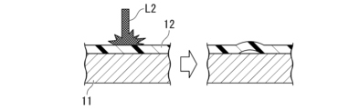
- FIG. 1 is a schematic diagram of a method for manufacturing a laminated metal sheet according to the present disclosure.
- FIG. 1 is a schematic diagram of a method for producing a laminated metal sheet by irradiating only far-infrared laser light.
- FIG. 1 is a schematic diagram of a method for producing a laminated metal sheet by irradiating only ultraviolet laser light and/or near-infrared laser light.
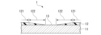
- FIG. 2 is a schematic cross-sectional view of an exposed portion of a laminated metal sheet according to the present disclosure.
- FIG. 1 is a cross-sectional photograph of an exposed portion in an example of a laminated metal sheet according to the present disclosure.
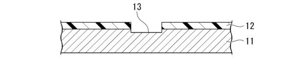
- FIG. 3 is a schematic cross-sectional view of an exposed portion of a laminated metal sheet from which a resin coating has been removed by mechanical means.
- FIG. FIG. 1 is a plan view of an example of a laminated metal sheet according to the present disclosure.
- FIG. 2 is a schematic diagram of another example of a laminated metal sheet according to the present disclosure. Photographs of the surfaces of laminated metal sheets irradiated with various lasers.
- FIG. 9B is an explanatory diagram obtained by tracing the photograph of FIG. 9A. 1 is a cross-sectional photograph of an area A that is not irradiated with laser light. 1 is a cross-sectional photograph of region B irradiated only with CO2 laser light.
- 13 is a cross-sectional photograph of region C that was irradiated with CO2 laser light and then with ultraviolet laser light. 13 is a cross-sectional photograph of region D irradiated only with ultraviolet laser light. This is a comparative diagram showing cross-sectional photographs of areas A to D.
- the manufacturing method of the laminated metal sheet 1 aims to provide a laminated metal sheet 1 having an exposed portion 13 where a base metal sheet 11 is exposed, and as illustrated in FIG. 1 , (S1) irradiates an original sheet of the laminated metal sheet 1, which includes a base metal sheet 11 and a resin coating 12 covering one or both surfaces of the base metal sheet 11, with far-infrared laser light L1 to alter the resin coating 12 in the irradiated area; (S2) A process of irradiating the area where the resin coating 12 has been altered with ultraviolet laser light and/or near-infrared laser light L2 to remove the resin coating 12 so as to expose the base metal plate 11.
- an original sheet of the laminated metal sheet 1 is prepared.
- the original sheet of the laminated metal sheet 1 includes a base metal sheet 11 and a resin coating 12 covering one or both surfaces of the base metal sheet 11.
- the resin coating 12 of the original sheet covers one or both surfaces of the base metal sheet 11 of the original sheet over its entirety.
- the original sheet has the same configuration as the laminated metal sheet 1 to be finally obtained, except that it does not have an exposed portion 13.
- a commercially available ordinary laminated metal sheet 1 can be used as the original sheet.
- the original plate is irradiated with far-infrared laser light L1.
- the far-infrared laser light L1 means a laser light in a wavelength range that is directly converted into vibrational energy or rotational energy of molecules or atoms without being converted into other forms of energy when absorbed by a substance.
- the far-infrared laser light L1 is, for example, a CO2 laser light.
- the far-infrared laser light L1 may be irradiated continuously or intermittently.
- the resin coating 12 may be altered by irradiation with the far-infrared laser light L1.
- the alteration of the resin coating 12 refers to a physical or chemical change in the state of the resin coating 12 from the original state.
- the deterioration of the resin coating 12 and its removal from the original sheet of the laminated metal sheet 1 are also included in the "alteration of the resin coating 12". That is, a part or all of the resin coating 12 at the irradiated portion may be removed from the laminated metal sheet 1 by irradiation with the far-infrared laser light L1.
- the irradiation with the far-infrared laser light L1 is sufficient to cause some alteration in the resin coating 12.
- the thickness of the resin coating 12 remaining after irradiation with the far-infrared laser beam L1 is set to be less than 17 ⁇ m. If the thickness of the resin coating 12 remaining after irradiation with the far-infrared laser beam L1 is less than 17 ⁇ m, the remaining resin coating 12 can be easily removed from the original plate by irradiating it with an ultraviolet laser beam and/or a near-infrared laser beam L2 in the next step.
- the region where the resin coating 12 has been altered by irradiation with the far-infrared laser light L1 is further irradiated with ultraviolet laser light and/or near-infrared laser light L2.
- the ultraviolet laser light is a laser light having a wavelength shorter than that of visible radiation.
- the near-infrared laser light is a laser light having a wavelength adjacent to the visible range that may cause a photochemical reaction when absorbed by a substance.
- the ultraviolet laser light and/or near-infrared laser light L2 may be irradiated continuously or intermittently.
- the resin coating 12 is removed from the original sheet by irradiation with ultraviolet laser light and/or near-infrared laser light L2. This forms an exposed portion 13 where the base metal sheet 11 is exposed.
- the concept of "removing the resin coating 12" includes not only completely separating the resin coating 12 from the laminated metal sheet 1, but also deteriorating the resin coating 12 so that it can be easily separated from the laminated metal sheet 1 by simple means such as blowing air.
- the far-infrared laser light L1 is combined with the ultraviolet laser light and/or the near-infrared laser light L2. This makes it possible to easily remove the resin coating 12 from the original sheet.
- the inventors of the present invention presume that the reason for this effect is as follows.
- the far-infrared laser light L1 alone may not be able to deteriorate the resin coating 12 to a degree that makes it possible to remove the resin coating 12.
- the far-infrared laser light L1 can heat the resin coating 12 and reduce its thickness.
- the resin coating 12 becomes thinner due to irradiation with the far-infrared laser light L1
- the far-infrared laser becomes less likely to be absorbed by the resin coating 12.
- deterioration of the resin coating 12 due to irradiation with the far-infrared laser light L1 no longer progresses.
- the thickness of the polypropylene coating was reduced by irradiation with the far-infrared laser light L1.
- the thinned polypropylene coating was firmly attached to the base metal plate 11.
- the polypropylene coating irradiated only with the far-infrared laser light L1 could not be removed without using powerful machining means such as a grinding tool.
- the ultraviolet laser light and near-infrared laser light L2 alone may not be able to deteriorate the resin coating 12 to a degree that makes it possible to remove the resin coating 12.
- the ultraviolet laser light and near-infrared laser light L2 can peel the resin coating 12 from the base metal sheet 11.
- the ultraviolet laser light and near-infrared laser light L2 may not be able to separate the laser-irradiated resin coating 12 from the surrounding resin coating 12 that has not been irradiated with the laser.
- the energy of the ultraviolet laser light and near-infrared laser light L2 is easily absorbed by the base metal sheet 11. Therefore, when the ultraviolet laser light and near-infrared laser light L2 are increased, the base metal sheet 11 may melt before the resin coating 12 is sufficiently deteriorated.
- the polypropylene coating irradiated with ultraviolet laser light or near-infrared laser light L2 peeled off from the base metal plate 11.
- the polypropylene coating that peeled off from the base metal plate 11 was firmly connected to the surrounding polypropylene coating.
- the peeled off polypropylene coating could not be removed without using powerful machining means such as a grinding tool.
- the inventors have discovered that, as shown in Figure 1, by first irradiating the resin coating 12 with far-infrared laser light L1 and then irradiating the resin coating 12 with ultraviolet laser light and/or near-infrared laser light L2, the resin coating 12 deteriorates significantly and can be easily removed from the original plate.
- the inventors presume that by irradiating the resin coating 12 with ultraviolet laser light and/or near-infrared laser light L2 after thinning it with far-infrared laser light L1, the resin coating 12 that has peeled off from the base metal plate 11 becomes easily detached from the surrounding resin coating 12.
- a laminated metal plate 1 according to another aspect of the present disclosure is a laminated metal plate 1 comprising a base metal plate 11 and a resin coating 12 covering one or both surfaces of the base metal plate 11, wherein an exposed portion 13 in which the base metal plate 11 is exposed is provided on a portion of the surface of the laminated metal plate 1 on which the resin coating 12 is provided, and the resin coating 12 has a main body portion 121 and a transition portion 122 provided around the exposed portion 13, wherein in the main body portion 121, the interface between the base metal plate 11 and the resin coating 12 is approximately parallel to the surface of the resin coating 12, and in the transition portion 122, the surface of the resin coating 12 is inclined from the surface of the resin coating 12 in the main body portion 121 toward the surface of the base metal plate 11 in the exposed portion 13, and the area on the surface of the base metal plate 11 where the transition portion 122 is arranged is continuously connected to the area where the exposed portion 13 is arranged.
- the laminated metal sheet 1 comprises a base metal sheet 11 and a resin coating 12 that covers one or both surfaces of the base metal sheet 11.
- the resin coating 12 of the laminated metal sheet 1 covers one or both surfaces of the base metal sheet 11 of the laminated metal sheet 1. However, a portion of the resin coating 12 has been removed from the laminated metal sheet 1. The area where the resin coating 12 has been removed and the base metal sheet 11 is exposed is the exposed portion 13.
- the resin coating 12 of the laminated metal sheet 1 according to this embodiment has a specific shape around the exposed portion 13. As shown in Fig. 4, the resin coating 12 is divided into a main body portion 121 and a transition portion 122 provided around the exposed portion 13.
- the interface between the base metal sheet 11 and the resin coating 12 is approximately parallel to the surface of the resin coating 12. That is, the thickness of the resin coating 12 in the main body portion 121 is approximately constant.
- the resin coating 12 in the main body portion 121 is the same as the resin coating 12 of the laminated metal sheet 1 (i.e., the original sheet described above) before the resin coating 12 is removed.
- the interface between the base metal sheet 11 and the resin coating 12 is not approximately parallel to the surface of the resin coating 12.
- the surface of the resin coating 12 is inclined from the surface of the resin coating 12 in the main body portion 121 toward the surface of the base metal sheet 11 in the exposed portion 13. That is, the thickness of the resin coating 12 in the transition portion 122 decreases as it approaches the exposed portion 13.
- the transition portion 122 separates the main body portion 121 from the exposed portion 13.
- the transition portion 122 is created by removing the resin coating 12 using laser light.
- FIG. 5 shows a cross-sectional photograph of the exposed portion 13 and its vicinity, which was formed by first irradiating the resin coating 12 with far-infrared laser light L1 and then irradiating the resin coating 12 with ultraviolet laser light and/or near-infrared laser light L2.
- FIG. 5 shows a photograph obtained by cutting the laminated metal sheet 1 at the exposed portion 13 of the laminated metal sheet 1 along a plane perpendicular to the direction in which the exposed portion 13 extends, embedding the laminated metal sheet 1 in resin for cross-sectional observation 2, polishing the cut surface of the laminated metal sheet 1, and photographing the cut surface through an optical microscope.
- the angle and strength of the illumination were optimized so that the interface between the resin for cross-sectional observation 2 in which the laminated metal sheet 1 is embedded and the resin coating 12 of the laminated metal sheet 1 would be clear.
- the cross section of the base metal sheet 11 is whited out in FIG. 5.
- a transition portion 122 is formed around the exposed portion 13 formed using the laser beam.
- the area on the surface of the base metal plate 11 where the transition portion 122 is arranged is continuously connected to the area on the surface of the base metal plate 11 where the exposed portion 13 is arranged.
- the surface of the base metal plate 11 of the original plate in the laser beam irradiation area is flat, the surface of the base metal plate 11 will also be flat in the exposed portion 13 formed using the laser beam. In addition, even if the surface of the base metal plate 11 is not flat because the base metal plate 11 has been bent, etc., no unevenness (e.g., cutting marks) formed by machining is generated in the exposed portion 13 formed using the laser beam.
- no transition portion 122 is formed around the exposed portion 13 formed by machining such as grinding. Furthermore, when the resin coating 12 is removed by machining, some of the surface layer of the base metal plate 11 is also removed. Therefore, in the exposed portion 13 formed by machining, a recess is formed on the surface of the base metal plate 11.
- a laminated metal plate 1 in which a transition portion 122 is provided around the exposed portion 13 and in which the area on the surface of the base metal plate 11 where the transition portion 122 is located is continuously connected to the area where the exposed portion 13 is located, it is highly likely that the exposed portion 13 is formed by irradiation with laser light. Therefore, a laminated metal plate 1 in which a transition portion 122 is provided around the exposed portion 13 can be easily manufactured.
- the thickness of the resin coating 12 is not particularly limited. In order to increase the corrosion resistance of the laminated metal sheet 1, it is preferable that the thickness of the resin coating 12 is large. For example, it is preferable that the thickness of the resin coating 12 of the original sheet and/or the thickness of the resin coating 12 in the main body portion 121 of the laminated metal sheet 1 is 18.0 ⁇ m or more, 20.0 ⁇ m or more, or 30.0 ⁇ m or more.
- Thick polyolefin-based resins and polypropylene-based resins are difficult to remove using laser light.
- thick polyolefin-based resins and polypropylene-based resins have been removed by mechanical means such as grinding.
- the thick polyolefin-based resins and polypropylene-based resins can be easily removed from the original sheet to form the exposed portion 13.
- the shape of the exposed portion 13 in plan view is not particularly limited. Any shape of the exposed portion 13 suitable for the application of the laminated metal sheet 1 and the application of the exposed portion 13 can be adopted.
- the exposed portion 13 preferably has a band-like shape extending along the edge of the laminated metal plate 1 as illustrated in FIG. 7. Furthermore, when manufacturing the laminated metal plate 1, it is preferable to remove the resin coating 12 along the edge of the original plate, thereby forming the exposed portion 13 having a band-like shape extending along the edge of the laminated metal plate 1.
- lap welding e.g., lap laser welding
- the coverage rate of the resin coating 12 on the laminated metal sheet 1 is not particularly limited. It can be set appropriately depending on the size and shape of the laminated metal sheet 1 and the size and shape of the exposed portion 13. In order to improve the corrosion resistance of the laminated metal sheet 1, it is preferable that the coverage rate of the resin coating 12 on the laminated metal sheet 1 is large. For example, it is preferable that the coverage rate of the resin coating 12 on the laminated metal sheet 1 is 50% or more, 70% or more, or 90% or more.
- the coverage rate of the resin coating 12 on the laminated metal sheet 1 represents the proportion of the area of the resin coating 12 on one side of the laminated metal sheet 1 after laser irradiation, when the area of one side of the original sheet is taken as 100%.
- the distance between the exposed portion 13 and the edge of the laminated metal plate 1 is greater than 0 mm and less than or equal to 15 mm.
- the exposed portion 13 extends continuously along the edge of the laminated metal plate 1.
- the width of the exposed portion 13 is, for example, 1.5 to 15 mm.
- the laminated metal plate 1 When the laminated metal plate 1 is used as a side wall of a pail can, the laminated metal plate 1 is rectangular. As illustrated in FIG. 8, the laminated metal plate 1 is rolled and the two opposing ends of the laminated metal plate 1 are seam welded. This makes the laminated metal plate 1 cylindrical. By providing a strip-shaped exposed portion 13 extending along the two parallel ends of the laminated metal plate 1 and overlapping and welding the exposed portion 13, a weld bead without welding defects can be formed. In the example shown in FIG. 8, both sides of the base metal plate 11 are covered with a resin coating 12. Therefore, the strip-shaped exposed portion 13 is provided on both sides of the laminated metal plate 1. In FIG. 8, only the exposed portion 13 on the surface facing outward of the laminated metal plate 1 is shown, but the exposed portion 13 on the surface facing inward is similarly provided at the same position as the exposed portion 13 on the surface facing outward.
- the wavelength of the far-infrared laser light L1 is not limited, but is preferably, for example, 9.2 to 10.8 ⁇ m.
- the wavelengths of the ultraviolet laser light and the near-infrared laser light L2 are also not particularly limited, but for example, the ultraviolet laser light is preferably 0.24 to 0.40 ⁇ m, and the near-infrared laser light is preferably 0.79 to 1.09 ⁇ m.
- the laser light of the above-mentioned wavelength is most suitable for removing the resin coating 12 mainly composed of polypropylene-based resin.
- the near-infrared laser light include a fiber laser, a disk laser, and a semiconductor laser.
- the irradiation conditions of the laser light other than the wavelength can be appropriately set according to the type and thickness of the resin coating 12.
- the shape of the transition portion 122 of the resin coating 12 is not particularly limited as long as the surface of the resin coating 12 is inclined from the surface of the resin coating 12 in the main body portion 121 toward the surface of the base metal sheet 11 in the exposed portion 13.
- the shape of the transition portion 122 changes depending on the irradiation conditions of the laser light when forming the exposed portion 13. For example, it is preferable that the angle between the surface of the base metal sheet 11 and the surface of the resin coating is 5 to 70 degrees. This makes it possible to remove the resin coating 12 even more easily.
- the type of base metal sheet 11 is not particularly limited. Suitable examples of the base metal sheet 11 include a steel sheet, an aluminum sheet, a titanium sheet, and a stainless steel sheet.
- the base metal sheet 11 may be a plated steel sheet. Suitable examples of the plated steel sheet include a zinc-based plated steel sheet, an aluminum-based plated steel sheet, a nickel-based plated steel sheet, and a chromate-treated steel sheet.
- a welded product according to another aspect of the present disclosure includes the laminated metal sheet 1 according to the present embodiment, a workpiece joined to the laminated metal sheet 1, and a welded portion provided at the exposed portion 13 of the laminated metal sheet 1 to join the laminated metal sheet 1 and the workpiece.
- a battery cell according to another aspect of the present disclosure includes the welded product according to the present embodiment.
- a manufacturing method for a welded product according to another aspect of the present disclosure includes a step of welding the laminated metal sheet 1 obtained by the manufacturing method for the laminated metal sheet 1 according to the present embodiment to the workpiece, and welding the area where the resin coating 12 has been removed.
- a manufacturing method for a battery cell according to another aspect of the present disclosure includes the manufacturing method for a welded product according to the present embodiment.
- the type of welded product is not particularly limited. Various products that can be manufactured using the laminated metal sheet 1 as a material can be used as the welded product of this embodiment. Suitable examples of welded products include battery cells, pails, beverage cans, roofs and walls of buildings, heat exchangers, and cooling devices for electric vehicles, etc.
- the material to be welded can be any material that can be welded to the base metal plate 11 of the laminated metal plate 1.
- the material to be welded may be the laminated metal plate 1.
- the material to be welded is the laminated metal plate 1, i.e., when two laminated metal plates 1 are joined to produce a welded product, it is preferable to provide an exposed portion 13 on each of the two laminated metal plates 1 and to overlap these exposed portions 13 for welding.
- the laminated metal sheet 1 and the material to be welded it is preferable not to bring the molten metal into contact with the resin coating 12. In a welded product, it is preferable that the weld metal formed by solidifying the molten metal is separated from the resin coating 12.
- a welded product having a welded portion having the regions (1), (2), and (3) above is considered to be a welded product according to this embodiment.
- the fusion portion may have low liquid-tightness.
- the joint is a welded portion.
- the welded portion can prevent moisture from penetrating into the welded product.
- the welded portion is an exposed portion 13, and the resin coating 12 does not affect the welding. The exposed portion 13 can suppress the occurrence of welding defects in the weld bead of the welded portion.
- the laminated metal plates are joined by surface by thermal fusion, and further, a joint structure is formed in which laser welding of an overlap, fillet, or edge structure is used in the exposed portion in the vicinity of the joint, thereby more effectively suppressing the penetration of moisture.
- a heat fusion joint can be formed on the joining surfaces of the laminated metal sheets away from the laser weld, resulting in a joint structure with no welding defects and with high moisture intrusion prevention capabilities that also uses heat fusion.
- the conditions in the example are merely one example of conditions adopted to confirm the feasibility and effects of the present disclosure.
- the present disclosure is not limited to this one example of conditions.
- Various conditions may be adopted in the present disclosure as long as they do not deviate from the gist of the present disclosure and the purpose of the present disclosure is achieved.
- Example A A base plate having a base metal plate and a resin coating covering one surface of the base metal plate was used as a sample for the experiment.
- the base metal plate was a tin-free steel plate having a thickness of 0.3 mm.
- the resin coating was a polypropylene coating (PP) or a polyethylene terephthalate coating (PET). The type and thickness of the resin coating of the sample are shown in Table 1.
- the laser light irradiation conditions listed in Table 1 were, in principle, as follows. However, for the laser light irradiated to some samples, some of the irradiation conditions were changed, and the output and number of irradiations in these cases are listed in the "Removal method" column in Table 1. "Number of repetitions” refers to the number of irradiations.
- Fiber laser light near-infrared laser light
- Wavelength 1.07 ⁇ m
- Light collection diameter 0.68 mm
- Output 500W
- Pulse frequency 60kHz
- ⁇ Scanning speed 3000 to 9000 mm/s
- ⁇ Number of repetitions 1 ⁇ Galvano scanner processing range: 5 mm width
- UV laser light irradiation conditions Wavelength: 0.355 ⁇ m
- the resin coating In the samples in which the resin coating was first irradiated with far-infrared laser light ( CO2 laser light) and then with ultraviolet laser light and/or near-infrared laser light (fiber laser light), the resin coating could be easily removed to form an exposed portion. When the cross sections of the exposed portions of these samples were observed, a slope was formed. Furthermore, the surfaces of the base metal plates of these samples were not deformed and were flat.
- CO2 laser light far-infrared laser light
- fiber laser light ultraviolet laser light and/or near-infrared laser light
- Example 6 the samples were irradiated with far-infrared laser light, but not with ultraviolet laser light and/or near-infrared laser light.
- the thickness of the resin coating was reduced, but the resin coating could not be deteriorated to the extent that it could be easily separated from the base metal plate with air.
- Example 13 the number of times that the far-infrared laser light was irradiated was increased compared to the other examples, but the resin coating could not be deteriorated to the extent that it could be easily separated from the base metal plate with air.
- Example 14 the output of the far-infrared laser light was increased compared to the other examples, but as a result, the base metal plate melted.
- Example 7 the resin coating was first irradiated with fiber laser light, and then irradiated with ultraviolet laser light.
- the resin coating was first irradiated with ultraviolet laser light, and then irradiated with fiber laser light.
- Example 11 the resin coating was irradiated with only fiber laser light. That is, in Examples 7, 9, and 11, the samples were not irradiated with far-infrared laser light. In the samples of Examples 7, 9, and 11, the resin coating peeled off from the base metal plate, but the resin coating could not be deteriorated to such an extent that it could be easily separated from the base metal plate with air.
- Example 8 the resin coating was first irradiated with ultraviolet laser light, and then irradiated with far-infrared laser light. In the sample of Example 8, the resin coating could not be completely removed.
- Example 17 the resin coating was mechanically cut off. As a result, in Example 17, the resin coating could be removed to form an exposed portion. However, in Example 17, irregularities were formed on the surface of the base metal plate. In Example 17, the strength of the base metal plate may have been impaired. Also, in Example 17, a sloped portion was not formed around the exposed portion.
- Example 18 the output of the CO2 laser light was 120 W, and the number of irradiations was 1. As a result, after the CO2 laser light irradiation, the thickness of the resin coating remaining in the portion irradiated with the CO2 laser light was 17 ⁇ m or more. In Example 18, the resin coating could not be removed from the original plate by the irradiation of the fiber laser light, and an exposed portion could not be formed. In Example 19, the output of the CO2 laser light was 360 W, and the number of irradiations was 3. As a result, the thickness of the resin coating remaining in the portion irradiated with the CO2 laser light after the CO2 laser light irradiation was less than 17 ⁇ m. In Example 19, the remaining resin coating was removed from the original plate by the irradiation of the fiber laser light, and an exposed portion was formed.
- UV laser light irradiation conditions Wavelength: 0.355 ⁇ m Pulse width: 20ns Repetition: 50kHz Average output: 6W (on WORK) ⁇ f ⁇ lens focal length: 250mm Light collection diameter: 38 ⁇ m Galvano scanner processing range: 4 mm width
- FIG. 9A A photograph of the resin coating 12 after irradiation is shown in FIG. 9A.
- An explanatory diagram of a trace of the photograph of FIG. 9A is shown in FIG. 9B.
- the region marked with the symbol A is a region that was not irradiated with laser.
- the region marked with the symbol B is a region that was irradiated only with CO2 laser light.
- the region marked with the symbol C is a region that was irradiated with UV laser light after irradiating with CO2 laser light.
- the region marked with the symbol D is a region that was irradiated only with UV laser light.
- FIG. 10A is a cross-sectional photograph of region A that was not irradiated with laser.
- FIG. 10B is a cross-sectional photograph of region B that was irradiated with only CO2 laser light.
- FIG. 10C is a cross-sectional photograph of region C that was irradiated with CO2 laser light and then with ultraviolet laser light.
- FIG. 10D is a cross-sectional photograph of region D that was irradiated with only ultraviolet laser light. Note that resin 2 for cross-section observation in which a sample is embedded is shown at the top of FIGS. 10A to 10D.
- FIG. 11 is a comparative diagram showing cross-sectional photographs of regions A to D lined up side by side.
- region C shown in FIG. 10C which was irradiated with CO2 laser light and then with an ultraviolet laser, the resin coating 12 peeled off, and an exposed portion 13 in which the base metal plate 11 is exposed was formed.
Landscapes
- Chemical & Material Sciences (AREA)
- Chemical Kinetics & Catalysis (AREA)
- Electrochemistry (AREA)
- General Chemical & Material Sciences (AREA)
- Physics & Mathematics (AREA)
- Optics & Photonics (AREA)
- Engineering & Computer Science (AREA)
- Inorganic Chemistry (AREA)
- Plasma & Fusion (AREA)
- Mechanical Engineering (AREA)
- Laminated Bodies (AREA)
Priority Applications (2)
| Application Number | Priority Date | Filing Date | Title |
|---|---|---|---|
| CN202480024066.6A CN120897822A (zh) | 2023-09-14 | 2024-09-13 | 层压金属板、焊接品、电池单元、层压金属板的制造方法、焊接品的制造方法以及电池单元的制造方法 |
| JP2025523851A JP7741462B2 (ja) | 2023-09-14 | 2024-09-13 | ラミネート金属板、溶接品、電池セル、ラミネート金属板の製造方法、溶接品の製造方法、及び電池セルの製造方法 |
Applications Claiming Priority (2)
| Application Number | Priority Date | Filing Date | Title |
|---|---|---|---|
| JP2023-149240 | 2023-09-14 | ||
| JP2023149240 | 2023-09-14 |
Publications (1)
| Publication Number | Publication Date |
|---|---|
| WO2025058062A1 true WO2025058062A1 (ja) | 2025-03-20 |
Family
ID=95021479
Family Applications (1)
| Application Number | Title | Priority Date | Filing Date |
|---|---|---|---|
| PCT/JP2024/032892 Pending WO2025058062A1 (ja) | 2023-09-14 | 2024-09-13 | ラミネート金属板、溶接品、電池セル、ラミネート金属板の製造方法、溶接品の製造方法、及び電池セルの製造方法 |
Country Status (3)
| Country | Link |
|---|---|
| JP (1) | JP7741462B2 (https=) |
| CN (1) | CN120897822A (https=) |
| WO (1) | WO2025058062A1 (https=) |
Citations (5)
| Publication number | Priority date | Publication date | Assignee | Title |
|---|---|---|---|---|
| JPH07290258A (ja) * | 1994-03-04 | 1995-11-07 | Nippon Steel Corp | 溶接用ラミネート鋼板の製造方法 |
| JP2001150590A (ja) * | 1999-11-25 | 2001-06-05 | Mitsubishi Plastics Ind Ltd | 樹脂積層鋼板および金属缶 |
| JP2002224770A (ja) * | 2001-01-30 | 2002-08-13 | Daiwa Can Co Ltd | 3ピース缶用溶接缶胴の製造方法 |
| JP2004026306A (ja) * | 2002-04-30 | 2004-01-29 | Daiwa Can Co Ltd | 金属缶の開口カール部 |
| JP2015047638A (ja) * | 2013-09-04 | 2015-03-16 | 株式会社最新レーザ技術研究センター | ビーム分岐回転光学系を用いたレーザ加工法 |
Family Cites Families (1)
| Publication number | Priority date | Publication date | Assignee | Title |
|---|---|---|---|---|
| JP4038988B2 (ja) * | 2001-02-06 | 2008-01-30 | 株式会社トッパンNecサーキットソリューションズ | 多層プリント配線板用レーザ孔あけ加工機 |
-
2024
- 2024-09-13 WO PCT/JP2024/032892 patent/WO2025058062A1/ja active Pending
- 2024-09-13 CN CN202480024066.6A patent/CN120897822A/zh active Pending
- 2024-09-13 JP JP2025523851A patent/JP7741462B2/ja active Active
Patent Citations (5)
| Publication number | Priority date | Publication date | Assignee | Title |
|---|---|---|---|---|
| JPH07290258A (ja) * | 1994-03-04 | 1995-11-07 | Nippon Steel Corp | 溶接用ラミネート鋼板の製造方法 |
| JP2001150590A (ja) * | 1999-11-25 | 2001-06-05 | Mitsubishi Plastics Ind Ltd | 樹脂積層鋼板および金属缶 |
| JP2002224770A (ja) * | 2001-01-30 | 2002-08-13 | Daiwa Can Co Ltd | 3ピース缶用溶接缶胴の製造方法 |
| JP2004026306A (ja) * | 2002-04-30 | 2004-01-29 | Daiwa Can Co Ltd | 金属缶の開口カール部 |
| JP2015047638A (ja) * | 2013-09-04 | 2015-03-16 | 株式会社最新レーザ技術研究センター | ビーム分岐回転光学系を用いたレーザ加工法 |
Also Published As
| Publication number | Publication date |
|---|---|
| JPWO2025058062A1 (https=) | 2025-03-20 |
| JP7741462B2 (ja) | 2025-09-18 |
| CN120897822A (zh) | 2025-11-04 |
Similar Documents
| Publication | Publication Date | Title |
|---|---|---|
| US6540952B2 (en) | Laser ablation of multiple layers | |
| CN106029291B (zh) | 激光焊接方法 | |
| JP6930822B2 (ja) | 二次電池用電極及び二次電池 | |
| JP7815262B2 (ja) | 金属基板への金属箔スタックのレーザ溶接 | |
| JP5495118B2 (ja) | 亜鉛めっき鋼板のレーザ重ね溶接方法 | |
| JP3144317B2 (ja) | 積層製造方法 | |
| JP2009262186A (ja) | 金属メッキ板のレーザー溶接方法 | |
| JP6699007B2 (ja) | 亜鉛メッキ鋼板のレーザー接合方法 | |
| WO2013186862A1 (ja) | 溶接装置、溶接方法、及び電池の製造方法 | |
| WO2017122681A1 (ja) | レーザ重ね溶接方法 | |
| JP2016193814A (ja) | 脆性基板の切断方法 | |
| JP2013122973A (ja) | 金属箔の接続構造及びその接続方法及びコンデンサ | |
| US10894301B2 (en) | Method of removing a coating of organic material adhering to the surface of tin-plated sheet steel | |
| JP7741462B2 (ja) | ラミネート金属板、溶接品、電池セル、ラミネート金属板の製造方法、溶接品の製造方法、及び電池セルの製造方法 | |
| JP4232024B2 (ja) | 溶接ビード構造及び溶接方法 | |
| JP2010094702A (ja) | 金属メッキ板のレーザー溶接方法 | |
| JPH07290258A (ja) | 溶接用ラミネート鋼板の製造方法 | |
| JP2012228717A (ja) | レーザ溶接装置およびレーザ溶接方法 | |
| WO1998002261A1 (en) | Welding packaging containers | |
| JP2012228716A (ja) | レーザ溶接装置およびレーザ溶接方法 | |
| JPH0688392B2 (ja) | 積層体のスコア加工法及びスコア加工積層体 | |
| JP7712245B2 (ja) | 板材、接合体、板材の接合方法及び板材の製造方法 | |
| CN121938828A (zh) | 电极的制造方法 | |
| JP2004136980A (ja) | 引き裂き容易な包装袋 | |
| JP2006334641A (ja) | 薄板の縁継手レーザ溶接方法 |
Legal Events
| Date | Code | Title | Description |
|---|---|---|---|
| ENP | Entry into the national phase |
Ref document number: 2025523851 Country of ref document: JP Kind code of ref document: A |
|
| WWE | Wipo information: entry into national phase |
Ref document number: 2025523851 Country of ref document: JP |
|
| 121 | Ep: the epo has been informed by wipo that ep was designated in this application |
Ref document number: 24865561 Country of ref document: EP Kind code of ref document: A1 |
|
| WWE | Wipo information: entry into national phase |
Ref document number: CN2024800240666 Country of ref document: CN Ref document number: 202480024066.6 Country of ref document: CN |
|
| WWP | Wipo information: published in national office |
Ref document number: 202480024066.6 Country of ref document: CN |