WO2025057895A1 - ばね部材 - Google Patents
ばね部材 Download PDFInfo
- Publication number
- WO2025057895A1 WO2025057895A1 PCT/JP2024/032168 JP2024032168W WO2025057895A1 WO 2025057895 A1 WO2025057895 A1 WO 2025057895A1 JP 2024032168 W JP2024032168 W JP 2024032168W WO 2025057895 A1 WO2025057895 A1 WO 2025057895A1
- Authority
- WO
- WIPO (PCT)
- Prior art keywords
- coil spring
- insulator
- sheet
- adhesive
- spring
- Prior art date
- Legal status (The legal status is an assumption and is not a legal conclusion. Google has not performed a legal analysis and makes no representation as to the accuracy of the status listed.)
- Pending
Links
Images



Classifications
-
- F—MECHANICAL ENGINEERING; LIGHTING; HEATING; WEAPONS; BLASTING
- F16—ENGINEERING ELEMENTS AND UNITS; GENERAL MEASURES FOR PRODUCING AND MAINTAINING EFFECTIVE FUNCTIONING OF MACHINES OR INSTALLATIONS; THERMAL INSULATION IN GENERAL
- F16F—SPRINGS; SHOCK-ABSORBERS; MEANS FOR DAMPING VIBRATION
- F16F1/00—Springs
- F16F1/02—Springs made of steel or other material having low internal friction; Wound, torsion, leaf, cup, ring or the like springs, the material of the spring not being relevant
- F16F1/04—Wound springs
- F16F1/12—Attachments or mountings
Definitions
- the present invention relates to a spring member.
- a spring member that includes a coil spring made of wire wound in a spiral shape and a seat portion that is provided at the end of the coil spring and receives the load of the coil spring (see, for example, Patent Document 1).
- an elastic insulator is disposed between the coil spring and the seat portion, and the coil spring and the insulator are fixed together with an adhesive.
- spring components are required to be durable against high loads.
- the present invention was made in consideration of the above, and aims to provide a spring member that can improve durability against load.
- the spring member of the present invention comprises a coil spring made of wire wound in a spiral shape, and a sheet portion provided at an end of the coil spring and receiving the load of the coil spring, the sheet portion having a sheet covering a portion of one end of the coil spring, an insulator provided between the sheet and the coil spring, and an adhesive for bonding the insulator and the coil spring, the insulator being shaped such that a portion of the surface of the sheet side is cut out at the end on the edge side of the coil spring.
- the spring member according to the present invention is characterized in that, in the above invention, the insulator has an inclined surface formed on the sheet side at the end on the edge side of the coil spring.
- the spring member according to the present invention is characterized in that, in the above invention, the insulator has a curved surface formed on the sheet side at the end on the edge side of the coil spring.
- the spring member according to the present invention is characterized in that the insulator has an uneven surface on the seat side.
- the spring member according to the present invention is characterized in that the end of the adhesive on the coil spring side is flush with the edge of the coil spring.
- the present invention has the effect of providing a spring member that can improve durability against load.
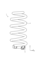
- FIG. 1 is a diagram showing a configuration of a spring member according to an embodiment of the present invention.
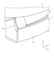
- FIG. 2 is an enlarged view of a portion of the spring member shown in FIG.
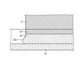
- FIG. 3 is an enlarged cross-sectional view of a portion of the spring member shown in FIG.
- FIG. 4 is a diagram for explaining deformation of the insulator when a load is applied to the spring member shown in FIG.
- FIG. 5 is a diagram for explaining an example of the configuration of a conventional spring member.
- FIG. 6 is a diagram for explaining deformation of the insulator when a load is applied to the spring member shown in FIG.
- FIG. 7 is a cross-sectional view showing a configuration of a spring member according to the first modification of the embodiment of the present invention.
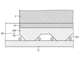
- FIG. 8 is a cross-sectional view showing a configuration of a spring member according to the second modification of the embodiment of the present invention.
- Fig. 1 is a diagram showing the configuration of a spring member according to an embodiment of the present invention.
- Fig. 2 is a diagram showing an enlarged portion of the spring member shown in Fig. 1.
- the spring member 1 includes a coil spring 2 formed by winding a wire in a spiral shape, and a seat portion 3 provided at an end of the coil spring 2 and receiving the load of the coil spring.
- the coil spring 2 is formed, for example, using flat spring steel made of metal, resin, etc.
- the wire is wound around an axis extending in the Z direction shown in FIG. 1.
- the sheet portion 3 has a sheet 31 that covers a portion of one end of the coil spring 2, an insulator 32 that is provided between the sheet 31 and the coil spring 2, and an adhesive 33 that bonds the insulator 32 and the coil spring 2 (see Figure 2).
- the sheet 31 is concave and covers a portion of the coil spring 2.
- the sheet 31 has a length less than one turn of the coil spring 2, and covers one end of the coil spring 2.
- the sheet 31 covers a portion of the side of the coil spring 2, and exposes the end face (the face intersecting with the longitudinal (extension) direction of the wire).
- the coil spring 2 can be displaced in the extension direction (Y direction shown in FIG. 2) by elastic deformation of the adhesive 33, etc.
- One turn here corresponds to one revolution around the winding axis of the wire of the coil spring 2.
- the end of the coil spring 2 on the sheet portion 3 side is taken as the base point (0th turn), and the winding position around the winding axis is expressed as the "turn".
- the first turn is the position equivalent to the above-mentioned one revolution from the base point.
- the insulator 32 is made of an elastic material, such as rubber, and is disposed between the sheet 31 and the coil spring 2 in the region where the sheet 31 is disposed.
- the adhesive 33 is, for example, a resin.
- the ends of the insulator 32 and adhesive 33 on the coil spring 2 side are positioned flush with the edge of the coil spring 2.
- the edge here corresponds to the outer edge that forms the end face of the coil spring 2.
- Fig. 3 is an enlarged cross-sectional view of a portion of the spring member shown in Fig. 1. As shown in Fig. 3, the insulator 32 and adhesive 33 are arranged between the coil spring 2 and the sheet 31, in that order from the sheet 31 side.
- the insulator 32 has an inclined surface 32a formed at the end on the sheet 31 side at the edge side of the coil spring 2.
- the inclined surface 32a is formed, for example, by chamfering the corners of the insulator 32, and the inclination angle ⁇ with respect to the end face on the adhesive 33 side is set in the range of more than 0° and less than 90°.
- a distance D1 from the end on the adhesive 33 side to a starting point P1 of the inclined surface 32a is set, and the length of the inclined surface 32a is determined according to the inclination angle ⁇ .
- the distance D1 is set to, for example, 1 mm.
- This inclined surface 32a forms a space between the inclined surface 32a and the sheet 31. In this manner, the surface of the insulator 32 facing the sheet 31 has a shape in which a part is cut out.
- FIG. 4 is a diagram for explaining the deformation of the insulator when a load is applied to the spring member shown in FIG. 3.
- the insulator 32 receives a load from the coil spring 2 side (see the arrow in FIG. 3)
- the insulator 32 deforms in response to the load.
- the deformation causes a lump of the insulator 32 to enter the space formed by the sheet 31 and the inclined surface 32a, and protrude from, for example, the end surface formed by the coil spring 2 and adhesive 33.
- the lump of the insulator 32 may become flush with the end surface formed by the coil spring 2 and adhesive 33, or may remain within the space formed by the sheet 31 and the inclined surface 32a.
- FIG. 5 is a diagram for explaining an example of the configuration of a conventional spring member.
- a configuration will be explained in which the end face of the insulator 320 is flush with the end face of the coil spring 2 and the end face of the adhesive 33 as shown in FIG. 5 when no load other than gravity is applied.
- Fig. 6 is a diagram for explaining deformation of the insulator when a load is applied to the spring member shown in Fig. 5.
- Fig. 6 shows an example in which the same load as that applied to the insulator 32 shown in Fig. 4 is applied. 5, when the insulator 320 receives a load from the coil spring 2 side (see the arrow in FIG. 5), the insulator 320 deforms in response to the load. At this time, the deformation causes a mass of the insulator 32 to significantly protrude from the end surface formed by the coil spring 2 and the adhesive 33.
- the amount of meat mass protruding from the end surface formed by the coil spring 2 and the adhesive 33 is less for the insulator 32 shown in FIG. 4 than for the insulator 320 shown in FIG. 6.
- the meat mass of the insulator 32 is partially chipped by the inclined surface 32a, so that the deformation of the insulator 32 is apparently suppressed.
- the lumps on the bottom side of the insulator exhibit a deformation behavior that actively protrudes to the opposite side to the adhesive (the sheet side), and this deformation also generates stress in the adhesive. Therefore, by removing the lumps at the edge of the insulator, the stress generated in the adhesive can be reduced by the amount removed. Therefore, in the configuration shown in Figures 3 and 4, the shear stress generated between the insulator 32 and the adhesive 33 is lower than in the conventional example (see Figures 5 and 6). As a result, in the configuration of this embodiment, the stress generated in the adhesive 33 is reduced.
- the ends of the insulator 32 and adhesive 33 on the coil spring 2 side are positioned flush with the end face of the coil spring 2, and an inclined surface 32a is formed on the sheet 31 side of the insulator 32.
- an inclined surface 32a is formed on the sheet 31 side of the insulator 32.
- Fig. 7 is a cross-sectional view showing the configuration of a spring member according to the first modified example of the embodiment of the present invention.
- the spring member described above includes a seat portion 3A instead of the seat portion 3. Note that the same components as those in the above-described embodiment are given the same reference numerals.
- the spring member in this modified example 1 comprises a coil spring 2 made of wire wound in a spiral shape, and a seat portion 3A that is provided at the end of the coil spring 2 and receives the load of the coil spring.
- the sheet portion 3A has a sheet 31 that covers a portion of one end of the coil spring 2, an insulator 32A that is provided between the sheet 31 and the coil spring 2, and an adhesive 33 that bonds the insulator 32A and the coil spring 2.
- the insulator 32A is made of an elastic material, such as rubber.
- the insulator 32A is disposed between the sheet 31 and the coil spring 2 within the area in which the sheet 31 is disposed.
- the ends of the insulator 32A and the adhesive 33 on the coil spring 2 side are positioned flush with the edge of the coil spring 2.
- the insulator 32A has a curved surface 32b formed at an end portion on the sheet 31 side at the edge side of the coil spring 2.
- the curved surface 32b is formed, for example, by chamfering a corner of the insulator 32A.
- This curved surface 32b forms a space between the curved surface 32b and the sheet 31.
- the curved surface 32b may be a concave curved surface. In this manner, the surface of the insulator 32A facing the sheet 31 is partially cut out.
- the insulator 32A In the state shown in FIG. 7, when the insulator 32A receives a load from the coil spring 2 side (see the arrow in FIG. 3), the insulator 32A deforms in response to this load. At this time, the deformation causes the meat of the insulator 32A to enter the space formed by the sheet 31 and the curved surface 32b, and protrudes from the end surface formed by the coil spring 2 and the adhesive 33, for example. Depending on the load, the meat of the insulator 32A may become flush with the end surface formed by the coil spring 2 and the adhesive 33, or may remain within the space formed by the sheet 31 and the inclined surface 32a.
- Fig. 8 is a cross-sectional view showing the configuration of a spring member according to the second modified example of the embodiment of the present invention.
- the spring member described above includes a seat portion 3B instead of the seat portion 3. Note that the same components as those in the above embodiment are denoted by the same reference numerals.
- the spring member in this modified example 2 comprises a coil spring 2 made of wire wound in a spiral shape, and a seat portion 3B that is provided at the end of the coil spring 2 and receives the load of the coil spring.
- the sheet portion 3B has a sheet 31 that covers a portion of one end of the coil spring 2, an insulator 32B that is provided between the sheet 31 and the coil spring 2, and an adhesive 33 that bonds the insulator 32B and the coil spring 2.
- the insulator 32B is made of an elastic material, such as rubber.
- the insulator 32B is disposed between the sheet 31 and the coil spring 2 within the area in which the sheet 31 is disposed.
- the ends of the insulator 32B and the adhesive 33 on the coil spring 2 side are positioned flush with the edge of the coil spring 2.
- the insulator 32B has a plurality of protruding portions 32c formed at the end portion on the sheet 31 side.
- the plurality of protruding portions 32c are formed, for example, by intermittently removing a portion of the surface of the insulator 32B on the sheet 31 side, and each protrudes in a frustum shape.
- the protruding portions 32c make the surface of the insulator 32B on the sheet 31 side uneven, and a space is formed between the recessed portion of the insulator 32B and the sheet 31. In this manner, the surface of the insulator 32B facing the sheet 31 is partially cut out.
- the insulator 32B In the state shown in FIG. 8, when the insulator 32B receives a load from the coil spring 2 side (see the arrow in FIG. 3), the insulator 32B deforms in response to this load. At this time, the deformation causes the convex portion 32c (lump) of the insulator 32B to enter the space formed by the concave portion of the insulator 32B and the sheet 31. This apparently suppresses the deformation of the insulator 32B. Therefore, in the configuration shown in FIG. 8, the shear stress generated between the insulator 32B and the adhesive 33 is lower than in the conventional example. As a result, in the configuration of this modified example 2, the stress generated in the adhesive 33 is reduced.
- this modified example 2 by forming the protrusions 32c (uneven shape) on the insulator 32B, when a load is applied to the sheet portion 3B side of the coil spring 2, the apparent deformation of the insulator 32B is suppressed and further the stress generated in the adhesive 33 is reduced, so that damage caused by the edge of the coil spring 2 biting into the adhesive 33 or the insulator 32B can be suppressed, and as a result, a spring member with improved durability against load can be obtained.
- the formation of multiple protrusions 32c increases the space into which the meat mass enters when the insulator 32B is deformed, compared to the configuration in the above-mentioned embodiment, so that the stress generated in the adhesive 33 can be further reduced.
- the present invention may include various embodiments not described here, and various design changes may be made without departing from the technical ideas defined by the claims.
- the positions of the ends of the insulator and adhesive on the coil spring side are flush with the end face of the coil spring (located on the same plane as the end face of the coil spring) have been described as examples, but the positions of the ends of the insulator and adhesive on the coil spring side are not limited to this, and may be offset from the end face of the coil spring in the extension direction of the coil spring.
- the spring member of the present invention is suitable for improving durability against load.
Landscapes
- Engineering & Computer Science (AREA)
- General Engineering & Computer Science (AREA)
- Mechanical Engineering (AREA)
- Springs (AREA)
Priority Applications (2)
| Application Number | Priority Date | Filing Date | Title |
|---|---|---|---|
| CN202480057527.XA CN121794494A (zh) | 2023-09-13 | 2024-09-09 | 弹簧部件 |
| JP2025545661A JPWO2025057895A1 (https=) | 2023-09-13 | 2024-09-09 |
Applications Claiming Priority (2)
| Application Number | Priority Date | Filing Date | Title |
|---|---|---|---|
| JP2023-148510 | 2023-09-13 | ||
| JP2023148510 | 2023-09-13 |
Publications (1)
| Publication Number | Publication Date |
|---|---|
| WO2025057895A1 true WO2025057895A1 (ja) | 2025-03-20 |
Family
ID=95021381
Family Applications (1)
| Application Number | Title | Priority Date | Filing Date |
|---|---|---|---|
| PCT/JP2024/032168 Pending WO2025057895A1 (ja) | 2023-09-13 | 2024-09-09 | ばね部材 |
Country Status (3)
| Country | Link |
|---|---|
| JP (1) | JPWO2025057895A1 (https=) |
| CN (1) | CN121794494A (https=) |
| WO (1) | WO2025057895A1 (https=) |
Citations (5)
| Publication number | Priority date | Publication date | Assignee | Title |
|---|---|---|---|---|
| US20140225319A1 (en) * | 2011-04-14 | 2014-08-14 | ThyssenKrupp Federn und Stabilisatoren GmbH | Bearing arrangement for a spring of a vehicle chassis |
| JP2015218828A (ja) * | 2014-05-19 | 2015-12-07 | 東洋ゴム工業株式会社 | スプリングシートラバー |
| JP2019157886A (ja) | 2018-03-07 | 2019-09-19 | 中央発條株式会社 | 車両用懸架装置用スプリング |
| JP2019163837A (ja) * | 2018-03-20 | 2019-09-26 | 住友理工株式会社 | インシュレータ |
| JP2023522765A (ja) * | 2020-04-27 | 2023-05-31 | ティッセンクルップ フェダーン ウント スタビリサトーレン ゲゼルシャフト ミット ベシュレンクテル ハフツング | シャシー用のばねアセンブリ、ばねアセンブリを備える乗り物シャシー、乗り物シャシー用のばねアセンブリを作製するための方法、及びばねアセンブリの使用 |
-
2024
- 2024-09-09 CN CN202480057527.XA patent/CN121794494A/zh active Pending
- 2024-09-09 JP JP2025545661A patent/JPWO2025057895A1/ja active Pending
- 2024-09-09 WO PCT/JP2024/032168 patent/WO2025057895A1/ja active Pending
Patent Citations (5)
| Publication number | Priority date | Publication date | Assignee | Title |
|---|---|---|---|---|
| US20140225319A1 (en) * | 2011-04-14 | 2014-08-14 | ThyssenKrupp Federn und Stabilisatoren GmbH | Bearing arrangement for a spring of a vehicle chassis |
| JP2015218828A (ja) * | 2014-05-19 | 2015-12-07 | 東洋ゴム工業株式会社 | スプリングシートラバー |
| JP2019157886A (ja) | 2018-03-07 | 2019-09-19 | 中央発條株式会社 | 車両用懸架装置用スプリング |
| JP2019163837A (ja) * | 2018-03-20 | 2019-09-26 | 住友理工株式会社 | インシュレータ |
| JP2023522765A (ja) * | 2020-04-27 | 2023-05-31 | ティッセンクルップ フェダーン ウント スタビリサトーレン ゲゼルシャフト ミット ベシュレンクテル ハフツング | シャシー用のばねアセンブリ、ばねアセンブリを備える乗り物シャシー、乗り物シャシー用のばねアセンブリを作製するための方法、及びばねアセンブリの使用 |
Also Published As
| Publication number | Publication date |
|---|---|
| JPWO2025057895A1 (https=) | 2025-03-20 |
| CN121794494A (zh) | 2026-04-03 |
Similar Documents
| Publication | Publication Date | Title |
|---|---|---|
| JP2647485B2 (ja) | 薄肉缶の底部構造 | |
| US10626942B2 (en) | Lower-side spring-receiving member | |
| US5625248A (en) | Piezoelectric buzzer | |
| US12217921B2 (en) | Vacuum circuit breaker | |
| WO2025057895A1 (ja) | ばね部材 | |
| JP2009545288A (ja) | バネ要素及びバネ要素を備えた圧電アクチュエータ | |
| US6050557A (en) | Coiled disk spring | |
| US10770252B2 (en) | Magnetic system of electromagnetic relay | |
| US9403430B2 (en) | Insulator | |
| JP2006029364A (ja) | ガスケット | |
| EP4056941B1 (en) | Heat exchange plate for plate heat exchanger, and plate heat exchanger | |
| US20020144857A1 (en) | Butterfly damper | |
| JP7519309B2 (ja) | 固定構造 | |
| JP2010173099A (ja) | タイヤ加硫成形用金型 | |
| JP2006127775A (ja) | 連続端子 | |
| JP2025014503A (ja) | 押圧ばね装置の製造方法 | |
| WO2018198471A1 (ja) | 空気入りタイヤ | |
| JP5838921B2 (ja) | コイル | |
| JP2011143918A (ja) | ウエザーストリップ用芯金 | |
| JP5819253B2 (ja) | 皿ばね | |
| JP4600867B2 (ja) | ペダルモジュール | |
| WO2019167932A1 (ja) | ウェーブスプリング | |
| JP6563670B2 (ja) | 取付部材 | |
| EP3613902B1 (en) | Fender device | |
| JP2002174282A (ja) | ウエーブコイルばね |
Legal Events
| Date | Code | Title | Description |
|---|---|---|---|
| 121 | Ep: the epo has been informed by wipo that ep was designated in this application |
Ref document number: 24865395 Country of ref document: EP Kind code of ref document: A1 |
|
| ENP | Entry into the national phase |
Ref document number: 2025545661 Country of ref document: JP Kind code of ref document: A |
|
| WWE | Wipo information: entry into national phase |
Ref document number: 2025545661 Country of ref document: JP |
|
| WWE | Wipo information: entry into national phase |
Ref document number: 2601001636 Country of ref document: TH |
|
| WWE | Wipo information: entry into national phase |
Ref document number: 2024865395 Country of ref document: EP |