WO2025057796A1 - 測定装置、測定プログラム、および、コンピュータプログラムを記録したコンピュータ読み取り可能な記録媒体 - Google Patents
測定装置、測定プログラム、および、コンピュータプログラムを記録したコンピュータ読み取り可能な記録媒体 Download PDFInfo
- Publication number
- WO2025057796A1 WO2025057796A1 PCT/JP2024/031434 JP2024031434W WO2025057796A1 WO 2025057796 A1 WO2025057796 A1 WO 2025057796A1 JP 2024031434 W JP2024031434 W JP 2024031434W WO 2025057796 A1 WO2025057796 A1 WO 2025057796A1
- Authority
- WO
- WIPO (PCT)
- Prior art keywords
- light
- seed
- laser
- output
- laser light
- Prior art date
- Legal status (The legal status is an assumption and is not a legal conclusion. Google has not performed a legal analysis and makes no representation as to the accuracy of the status listed.)
- Pending
Links
Images


Classifications
-
- G—PHYSICS
- G01—MEASURING; TESTING
- G01C—MEASURING DISTANCES, LEVELS OR BEARINGS; SURVEYING; NAVIGATION; GYROSCOPIC INSTRUMENTS; PHOTOGRAMMETRY OR VIDEOGRAMMETRY
- G01C3/00—Measuring distances in line of sight; Optical rangefinders
- G01C3/02—Details
- G01C3/06—Use of electric means to obtain final indication
-
- G—PHYSICS
- G01—MEASURING; TESTING
- G01S—RADIO DIRECTION-FINDING; RADIO NAVIGATION; DETERMINING DISTANCE OR VELOCITY BY USE OF RADIO WAVES; LOCATING OR PRESENCE-DETECTING BY USE OF THE REFLECTION OR RERADIATION OF RADIO WAVES; ANALOGOUS ARRANGEMENTS USING OTHER WAVES
- G01S17/00—Systems using the reflection or reradiation of electromagnetic waves other than radio waves, e.g. lidar systems
- G01S17/02—Systems using the reflection of electromagnetic waves other than radio waves
- G01S17/06—Systems determining position data of a target
- G01S17/08—Systems determining position data of a target for measuring distance only
- G01S17/10—Systems determining position data of a target for measuring distance only using transmission of interrupted, pulse-modulated waves
-
- G—PHYSICS
- G01—MEASURING; TESTING
- G01S—RADIO DIRECTION-FINDING; RADIO NAVIGATION; DETERMINING DISTANCE OR VELOCITY BY USE OF RADIO WAVES; LOCATING OR PRESENCE-DETECTING BY USE OF THE REFLECTION OR RERADIATION OF RADIO WAVES; ANALOGOUS ARRANGEMENTS USING OTHER WAVES
- G01S7/00—Details of systems according to groups G01S13/00, G01S15/00, G01S17/00
- G01S7/48—Details of systems according to groups G01S13/00, G01S15/00, G01S17/00 of systems according to group G01S17/00
- G01S7/483—Details of pulse systems
- G01S7/484—Transmitters
Definitions
- the technology disclosed in this specification relates to a measurement device, a measurement program, and a computer-readable recording medium on which a computer program is recorded.
- LiDAR Light Detection and Ranging
- a projector that projects (irradiates) laser light onto the measurement target, and a receiver that receives the reflected light that reflects the laser light off the measurement target.
- LiDAR outputs information about the measurement target by measuring the distance to the measurement target based on the time difference between the timing when the projector emits the laser light and the timing when the receiver receives the reflected light.
- the projector is equipped with a fiber laser (see, for example, Patent Document 1).
- a fiber laser has a seed laser that emits seed laser light, an optical fiber that is doped with a rare earth element and through which the seed laser light passes, and a pump laser that emits pump light that excites the rare earth element in the optical fiber.
- the measuring device disclosed in this specification has a first seed laser that emits a first seed laser light having a first wavelength, a second seed laser that emits a second seed laser light having a second wavelength different from the first wavelength, an optical fiber doped with a rare earth element and into which the first seed laser light and the second seed laser light are input, and an excitation laser that emits excitation light that excites the rare earth element in the optical fiber, and is equipped with a light projector that emits output laser light output from the optical fiber to the outside, a light receiver that receives reflected laser light that is reflected back from the measurement object when the output laser light emitted by the light projector is emitted, and a controller.
- the controller executes a seed laser emission process for emitting light from the first seed laser and the second seed laser for different periods of time, a first measurement process for measuring the distance to the measurement object based on a first light receiving timing at which the receiver receives a first reflected laser light, which is the output laser light output from the optical fiber in response to the input of the first seed laser light, reflected by the measurement object and returning, and a second measurement process for measuring the distance to the measurement object based on a second light receiving timing at which the receiver receives a second reflected laser light, which is the output laser light output from the optical fiber in response to the input of the second seed laser light, reflected by the measurement object and returning.
- this measuring device a first seed laser light and a second seed laser light having different wavelengths are input to a common optical fiber with a time difference. Therefore, the receiver can distinguish between a first reflected laser light corresponding to the first seed laser light and a second reflected laser light corresponding to the second seed laser light based on the difference in wavelength. As a result, this measuring device can prevent the receiver from being unable to distinguish between multiple reflected laser lights corresponding to each of the multiple seed laser lights emitted during different periods.
- the light receiver may have a distributor that distributes the first reflected laser light and the second reflected laser light, a first light receiving element that receives the first reflected laser light distributed by the distributor, and a second light receiving element that receives the second reflected laser light distributed by the distributor. According to this measuring device, it is possible to prevent the first reflected laser light and the second reflected laser light from being mixed and received by the light receiver, compared to a configuration that does not have a distributor, for example.
- the time difference between the timing of emitting the first seed laser light and the timing of emitting the second seed laser light may be configured to be shorter than the round-trip time of the output laser light to travel the measurable distance of the measuring device.
- the sampling rate can be improved by shortening the emission period of the output laser light, compared to a configuration in which, for example, after emitting the first seed laser light, the first reflected laser light is received, and then the second sheet laser light is emitted.
- the optical fiber includes a first optical fiber into which the first seed laser light and the second seed laser light are input, and a plurality of second optical fibers
- the pumping laser includes a first pumping laser that emits pumping light to excite the rare earth element of the first optical fiber, and a second pumping laser that emits pumping light to excite the rare earth element of the plurality of second optical fibers
- the projector further has a splitter that splits the first output laser light output from the first optical fiber into a plurality of the first output laser lights, and each of the plurality of first output laser lights is input to each of the plurality of second optical fibers, and the plurality of second output laser lights output from each of the plurality of second optical fibers may be output to the outside.
- the first output laser light output from the first optical fiber is split into a plurality of first output laser lights, and the split first output laser lights are further amplified in the second optical fiber.
- the measurement device disclosed in this specification does not have the configurations (1) to (3) above, but has a seed laser that emits seed laser light, an optical fiber doped with a rare earth element and into which the seed laser light is input, and an excitation laser that emits excitation light that excites the rare earth element in the optical fiber, a light projector that emits output laser light output from the optical fiber to the outside, and a light receiver that receives reflected laser light that is reflected back from the measurement object by the output laser light emitted by the light projector, and the fiber is a first optical fiber into which the seed laser light is input and a plurality of second optical fibers.
- the measurement program disclosed in this specification is a measurement program for causing a computer of a measurement device including a first seed laser that emits a first seed laser light having a first wavelength, a second seed laser that emits a second seed laser light having a second wavelength different from the first wavelength, a light projector having an optical fiber to which the first seed laser light and the second seed laser light are input, and a light receiver that receives reflected laser light that is the output laser light emitted by the light projector and reflected back from the object to be measured, to emit the first seed laser and the second seed laser for different periods of time.
- the program executes a seed laser emission process for emitting a seed laser beam from the optical fiber to the target, a first measurement process for measuring the distance to the target based on a first light receiving timing at which the receiver receives a first reflected laser beam from the output laser beam output from the optical fiber by inputting the first seed laser beam, and a second measurement process for measuring the distance to the target based on a second light receiving timing at which the receiver receives a second reflected laser beam from the output laser beam output from the optical fiber by inputting the second seed laser beam.
- This measurement program can prevent the receiver from being unable to distinguish between multiple reflected laser beams corresponding to the multiple seed laser beams emitted in different periods.
- the measuring device 10 is mounted, for example, on a vehicle (not shown) equipped with AD or ADAS. For example, while the vehicle is traveling, the measuring device 10 assists in the detection of objects such as people and other vehicles, and provides various information to other devices and users that is useful for ensuring the safety of the driver of the vehicle and those around the vehicle, and for reducing damage to surrounding objects while the vehicle is being driven.
- the measuring device 10 is a multi-channel LiDAR that simultaneously emits multiple output lights Lout.
- the measuring device 10 is also a scan-type LiDAR. Specifically, the measuring device 10 scans the measurement target (not shown) so that the irradiation positions of the multiple output lights Lout move in parallel with each other.
- the measuring device 10 includes a light projector 20 and a light receiver 30.
- the light projector 20 includes a fiber laser 22 that outputs output light Lout, and a light projection control device 26.
- the light projection control device 26 controls the emission of light by the fiber laser 22.
- the light projection control device 26 also inputs a signal indicating the timing of light emission by the fiber laser 22 to a controller 40, which will be described later.
- the light projection control device 26 periodically and repeatedly emits light from the fiber laser 22, for example, by periodically and repeatedly turning on and off the current flowing through the fiber laser 22 (seed lasers 112a to 112c, which will be described later).
- the light projector 20 is a multi-channel light projector that simultaneously emits multiple output lights Lout (Lout1 to Lout6).
- the fiber laser 22 has a light emitting unit 110, a first excitation laser 120a, a second excitation laser 120b, a first optical fiber F1, and multiple second optical fibers F2.
- the light emitting unit 110 has seed lasers 112a to 112c, which will be described later, and each of the seed lasers 112a to 112c emits seed light La (La(f1) to La(f3) see FIG. 2) whose peak wavelength is within the near-infrared range, for example.
- the first optical fiber F1 and the second optical fiber F2 are doped with a rare earth element, and the seed light La passes through them.
- the first optical fiber F1 and the second optical fiber F2 are arranged in series.
- the optical fibers F1 and F2 are doped with at least one of the rare earth elements, for example ytterbium (Yb) and erbium (Er).
- the length of each of the optical fibers F1 and F2 is, for example, about 5 m.
- the first excitation laser 120a emits a first excitation light Lb1 (e.g., 940 nm) that excites the rare earth element contained in the first optical fiber F1.
- the second excitation laser 120b emits a second excitation light Lb2 (e.g., 940 nm) that excites the rare earth element contained in the second optical fiber F2.
- the fiber laser 22 has a first optical isolator (ISO) 130, a first multiplexer (WDM) 140, a first seed light splitter (TAP) 150a, a pump light splitter 150b, a second optical isolator 160, second multiplexers 170a to 170c, and second seed light splitters 180a to 180c.
- the first seed light splitter 150a is an example of a first splitter
- the second seed light splitters 180a to 180c are an example of a second splitter.
- the light emitting unit 110 is optically coupled to the first multiplexer 140 via a normal optical fiber (not shown) that is not doped with a rare earth element.
- a first optical isolator 130 is provided between the light emitting unit 110 and the first multiplexer 140.
- the first multiplexer 140 is coupled to the input portion of the first optical fiber F1.
- the output portion of the first optical fiber F1 is optically coupled to the first seed light splitter 150a.
- a second optical isolator 160 is provided between the first multiplexer 140 and the first seed light splitter 150a.
- the first seed light splitter 150a splits the seed light La amplified by the first optical fiber F1 into multiple lights (La1 to La3).
- the first excitation laser 120a is optically coupled to the first multiplexer 140 via a normal optical fiber (not shown) that is not doped with a rare earth element.
- the first multiplexer 140 multiplexes the seed light La emitted by the light emitting unit 110 and the first excitation light Lb1 emitted by the first excitation laser 120a.
- the second excitation laser 120b is optically coupled to the excitation light splitter 150b via a normal optical fiber (not shown) that is not doped with a rare earth element.
- the excitation light splitter 150b splits the second excitation light Lb2 emitted by the second excitation laser 120b into multiple lights.
- the second multiplexers 170a to 170c are each optically coupled to the first seed light splitter 150a and the pump light splitter 150b. Each of the second multiplexers 170a to 170c combines the seed light La amplified by the first optical fiber F1 with the second pump light Lb2 emitted by the second pump laser 120b.
- Each of the second multiplexers 170a to 170c is coupled to the input portion of the second optical fiber F2.
- the output portion of each of the second optical fibers F2 is coupled to each of the second seed light splitters 180a to 180c.
- the second multiplexer 170a is optically coupled to the second seed light splitter 180a via the second optical fiber F2.
- the second multiplexer 170b is optically coupled to the second seed light splitter 180b via the second optical fiber F2.
- the second multiplexer 170c is optically coupled to the second seed light splitter 180c via the second optical fiber F2.
- Each of the second seed light splitters 180a to 180c splits the seed light La1 to La3, which has been further amplified by the second optical fiber F2, into multiple beams.
- Each of the second seed light splitters 180a to 180c is coupled to the inputs of multiple third optical fibers F3.
- the output of each of the third optical fibers F3 is directed toward the outside of the projector 20.
- the third optical fibers F3 are normal optical fibers that are not doped with rare earth elements.
- the rare earth element contained in the first optical fiber F1 is excited by the first excitation light Lb1 emitted by the first excitation laser 120a, and the rare earth element contained in the second optical fiber F2 is excited by the second excitation light Lb2 emitted by the second excitation laser 120b.
- the seed light La is amplified by the first optical fiber F1 and is split into multiple lights (La1 to La3) by the first seed light splitter 150a.
- the first seed light La1 split by the first seed light splitter 150a is amplified in the second optical fiber F2 and further split into multiple lights by the second seed light splitter 180a.
- the multiple first seed light La1 split by the second seed light splitter 180a are each emitted to the outside of the projector 20 as a first output light Lout1 and a second output light Lout2 via a third optical fiber F3.
- the second seed light La2 split by the first seed light splitter 150a is amplified in the second optical fiber F2 and further split into multiple lights by the second seed light splitter 180b.
- the multiple second seed light beams La2 split by the second seed light splitter 180b are each outputted to the outside of the projector 20 as a third output light beam Lout3 and a fourth output light beam Lout4 via a third optical fiber F3.
- the third seed light beam La3 split by the first seed light splitter 150a is amplified by the second optical fiber F2 and further split into multiple beams by the second seed light splitter 180c.
- the multiple third seed light beams La3 split by the second seed light splitter 180c are each outputted to the outside of the projector 20 as a fifth output light beam Lout5 and a sixth output light beam Lout6 via a third optical fiber F3.
- the light receiver 30 has six light receiving sections 32 (32a to 32c).
- the light receiving section 32 is a receiving light source having one or more light receiving elements (not shown), or one or more light receiving element arrays (for example, light receiving elements arranged linearly (one-dimensionally) or planarly (two-dimensionally)).
- the light receiving elements are, for example, photodiodes, SPADs (Single Photon Avalanche Diodes), balanced photodetectors, etc.
- the light receiving section 32 photoelectrically converts the incident reflected light Lin to generate a current (hereinafter referred to as the "light receiving current") according to the intensity of the reflected light Lin.
- the light receiving section 32 inputs a signal indicating the timing at which the light receiving element constituting the light receiving section 32 receives the reflected light Lin, and the light receiving current generated by the light receiving element to the controller 40 described below.
- the first light receiving unit 32a is arranged to receive the first reflected light Lin1 that is the first output light Lout1 emitted by the projector 20 and reflected by the measurement object and returned.
- the second light receiving unit 32b is arranged to receive the second reflected light Lin2 that is the second output light Lout2 emitted by the projector 20 and reflected by the measurement object and returned.
- the third light receiving unit 32c is arranged to receive the third reflected light Lin3 that is the third output light Lout3 emitted by the projector 20 and reflected by the measurement object and returned.
- the fourth light receiving unit 32d is arranged to receive the fourth reflected light Lin4 that is the fourth output light Lout4 emitted by the projector 20 and reflected by the measurement object and returned.
- the fifth light receiving unit 32e is arranged to receive the fifth reflected light Lin5 that is the fifth output light Lout5 emitted by the projector 20 and reflected by the measurement object and returned.
- the sixth light receiving unit 32f is arranged to receive the sixth reflected light Lin6 that is the sixth output light Lout6 emitted by the projector 20 and reflected by the measurement object and returned.
- the projector 20 and the light receiver 30 are displaced relative to the measurement object, and the irradiation positions of the six output lights Lout1 to Lout3 on the measurement object are moved in parallel in a predetermined direction, so that information about the measurement object (such as the surface shape) can be obtained.
- the measuring device 10 further includes a controller 40 and a communication I/F (Inter face) 50.
- the controller 40 has, for example, a processor (CPU (Central Processing Unit), MPU (Micro Processing Unit), ASIC (Application Specific Integrated Circuit), FPGA (Field Programmable Gate Array), DSP (Digital Signal Processor), etc.).
- the controller 40 calculates the TOF based on a signal indicating the timing of light projection input from the light projection control device 26 and a signal indicating the timing of light reception input from the light receiving unit 32.
- the controller 40 generates information to be used for various measurements such as detection and distance measurement of the measurement target based on the input light reception current and the calculated TOF.
- the information is, for example, a histogram used in time-correlated single photon counting, the distance to each point of the measurement target, a point cloud (point cloud information), etc.
- the controller 40 also controls the light projection control device 26 and the light receiving unit 32.
- the controller 40 controls the light projection timing and light receiving timing described above, for example, by controlling the light projection control device 26 and the light receiving unit 32 so that the processing for generating the histogram is accelerated or optimized.
- the information generated by the controller 40 is provided (transmitted) to a device that uses the information (hereinafter referred to as "various use devices 60") via the communication I/F 50.
- the various utilization devices 60 perform, for example, the creation of environmental maps using point clouds, self-location estimation (SLAM (Simultaneous Localization and Mapping)) using scan matching algorithms (NDT (Normal Distributions Transform), ICP (Iterative Closest Point), etc.).
- SAM Simultaneous Localization and Mapping
- NDT Normal Distributions Transform
- ICP Iterative Closest Point
- A-2. Configuration of the light emitting unit 110 and the light receiving unit 32: 2 is an explanatory diagram showing a schematic configuration of the light emitting unit 110. As shown in FIG. 2, the light emitting unit 110 has a first seed laser 112a, a second seed laser 112b, a third seed laser 112c, and a third multiplexer 190. The first seed laser 112a, the second seed laser 112b, and the third seed laser 112c emit seed light La having different wavelengths.
- the first seed laser 112a emits seed light La (f1) having a wavelength of, for example, 1515 nm
- the second seed laser 112b emits seed light La (f2) having a wavelength of, for example, 1550 nm
- the third seed laser 112c emits seed light La (f3) having a wavelength of, for example, 1585 nm.
- the wavelength of each seed light La (f1 to f3) may be within a wavelength range (in this embodiment, 1500 nm or more and 1600 nm or less) that can be amplified by the first optical fiber F1 and the second optical fiber F2.
- the first seed laser 112a, the second seed laser 112b, and the third seed laser 112c are all optically coupled to the third multiplexer 190 via a normal optical fiber (not shown) that is not doped with rare earth elements.
- the third multiplexer 190 is optically coupled to the first multiplexer 140. With this configuration, the first seed laser 112a, the second seed laser 112b, and the third seed laser 112c are caused to emit light at different times, so that the light emitting unit 110 can selectively emit the seed light La(f1), the seed light La(f2), and the seed light La(f3).
- FIG. 3 is an explanatory diagram showing a schematic configuration of the light receiving unit 32.
- the light receiving unit 32 has a light receiving optical system 33, a dispersive element 35, three filters 34a to 34c, and three light receiving elements 36a to 36c.
- the dispersive element 35 is an example of a distributor.
- the light receiving optical system 33 collects the reflected light Lin that is the output light Lout from the projector 20 reflected by the measurement target or the like and returns.
- the light receiving optical system 33 is configured using optical components such as various lenses such as a collecting lens, various filters such as a wavelength filter, and a reflector (mirror).
- the dispersive element 35 is an element that disperses the reflected light Lin that passes through the light receiving optical system 33.
- the dispersive element 35 can be configured, for example, by a prism, a diffraction grating, a metamaterial, or the like.
- a metamaterial is an optical element in which microstructures smaller than the wavelength of light are arranged on a substrate (e.g., a glass substrate).
- the dispersive element 35 may be configured by a metamaterial in which microstructures are arranged three-dimensionally, or by a metamaterial (metasurface) in which microstructures are arranged two-dimensionally.
- the three filters 34a to 34c are each disposed at a position where the reflected light Lin dispersed by the dispersion element 35 is incident.
- the three filters 34a to 34c are bandpass filters that pass only light of different wavelength bands.
- the first filter 34a passes the reflected light Lin (f1) corresponding to the seed light La (f1) emitted by the first seed laser 112a, but does not pass the reflected light Lin (f2) and Lin (f3) corresponding to the seed light La (f2) and La (f3) emitted by the other seed lasers 112b and 112c.
- the passband of the first filter 34a is, for example, 1500 nm or more and 1530 nm or less.
- the second filter 34b passes the reflected light Lin (f2) and does not pass the reflected light Lin (f1) and Lin (f3). Specifically, the pass band of the second filter 34b is, for example, 1535 nm or more and 1565 nm or less.
- the third filter 34c passes the reflected light Lin (f3) but does not pass the reflected light Lin (f1) and Lin (f2). Specifically, the pass band of the third filter 34c is, for example, 1570 nm or more and 1600 nm or less.
- the first light receiving element 36a receives the reflected light Lin (f1) that has passed through the first filter 34a
- the second light receiving element 36b receives the reflected light Lin (f2) that has passed through the second filter 34b
- the third light receiving element 36c receives the reflected light Lin (f3) that has passed through the third filter 34c.
- FIG. 4 is a flow chart showing the measurement process
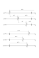
- FIG. 5 is a time chart showing the light projection timing and the light reception timing.
- the controller 40 causes the light projector 20 to start a light projection operation (S110). Specifically, the controller 40 executes a seed laser emission process in which the first seed laser 112a, the second seed laser 112b, and the third seed laser 112c emit light for different periods.
- the light emitter 110 alternately emits the seed light La (f1), the seed light La (f2), and the seed light La (f3) in this order with a predetermined emission time interval ⁇ T.
- the light projector 20 emits six output lights Lout1 to Lout3 from the third optical fiber F3 in an emission pattern in which three pulse waveforms having different wavelengths (f1 to f3) are sequentially repeated.
- the controller 40 determines whether the first reflected light Lin(f1) has been received by the first light receiving element 36a (S120). If the controller 40 determines that the first reflected light Lin(f1) has been received by the first light receiving element 36a (S120: YES), it executes a first measurement process (S130) and proceeds to S140. In the first measurement process, the distance to the measurement object is measured based on the first light receiving timing T4 at which the first reflected light Lin(f1) is received by the first light receiving element 36a. In other words, the fact that the first reflected light Lin(f1) has been received by the first light receiving element 36a means that the light receiver 30 has received the first reflected light Lin(f1) corresponding to the seed light La(f1).
- the controller 40 measures the distance to the measurement object based on, for example, the time difference ⁇ T1 between the emission timing T1 of the seed light La (f1) and the first reception timing T4. Note that when measuring the distance to the measurement object, the emission timing of the seed light La and the time difference ⁇ T1 may be corrected, for example, taking into account the length of the optical fibers (the first optical fiber F1, the second optical fiber F2, the third optical fiber F3, etc.) included in the fiber laser 22.
- the controller 40 determines whether the first reflected light Lin (f1) is not received by the first light receiving element 36a (S120: NO), it determines whether the second reflected light Lin (f2) is received by the second light receiving element 36b (S150). If the controller 40 determines that the second reflected light Lin (f2) is received by the second light receiving element 36b (S150: YES), it executes a second measurement process (S160) and proceeds to S140. In the second measurement process, the distance to the measurement object is measured based on the second light receiving timing T5 at which the second reflected light Lin (f2) is received by the second light receiving element 36b.
- the controller 40 measures the distance to the measurement target based on, for example, the time difference ⁇ T2 between the emission timing T2 of the seed light La (f2) and the second reception timing T5.
- the controller 40 determines whether the second reflected light Lin (f2) is not received by the second light receiving element 36b (S150: NO), it determines whether the third reflected light Lin (f3) is received by the third light receiving element 36c (S170). If the controller 40 determines that the third reflected light Lin (f3) is received by the third light receiving element 36c (S170: YES), it executes a third measurement process (S180) and proceeds to S140. In the third measurement process, the distance to the measurement object is measured based on the third light receiving timing T6 at which the third reflected light Lin (f3) is received by the third light receiving element 36c.
- the controller 40 measures the distance to the measurement target based on the time difference ⁇ T3 between the emission timing T3 of the seed light La (f3) and the third reception timing T6.
- the process proceeds to S140. If the controller 40 determines that an instruction to end measurement has not been received (S140: NO), the process returns to S120. If the controller 40 determines that an instruction to end measurement has been received (S140: YES), the process ends this measurement process.
- the light emission time interval ⁇ T which is the time difference between each light emission timing T1 to T3, is shorter than the round trip time (the maximum time difference between the light projection timing and the light reception timing) that the output light Lout takes to travel the measurable distance of the measuring device 10.
- the seed light La(f2) is emitted at the second light emission timing T2 without waiting for the arrival of the first light reception timing T4 of the first reflected light Lin(f1). Therefore, there is a high possibility that the second reflected light Lin(f2) will be received at 30 before the first reflected light Lin(f1).
- the first light reception timing T4 and the second light reception timing T5 can be distinguished based on the difference in wavelength. For example, if the measurable distance is 250 m, the round trip time is 1.7 ⁇ s, if the measurable distance is 500 m, the round trip time is 3.3 ⁇ s, and if the measurable distance is 750 m, the round trip time is 5.0 ⁇ s.
- the light emission time interval ⁇ T which is the time difference between each of the light emission timings T1 to T3 is shorter than the round trip time it takes for the output light Lout to travel back and forth over the measurable distance of the measurement device 10 (FIG. 5). Therefore, according to this embodiment, the sampling rate (measurement accuracy) can be improved by shortening the emission period of the output light Lout, compared to a configuration in which, for example, after the first light emission timing T1 of the seed light La(f1), the first reflected light Lin(f1) is received and then the seed light La(f2) is emitted.
- the seed light La output from the first optical fiber F1 is split into multiple seed lights La (La1 to La3) by the first seed light splitter 150a, and the multiple split seed lights La (La1 to La3) are further amplified by the second optical fiber F2 (FIG. 1).
- the second optical fiber F2 FOG. 1
- the second seed light La2 split by the first seed light splitter 150a is amplified by the second optical fiber F2 and further split into multiple lights by the second seed light splitter 180b (FIG. 1).
- the output light Lout can be further split into multiple lights and output while suppressing the occurrence of an output shortage of the output light Lout output from each second optical fiber F2.
- the first excitation laser 120a and the second excitation laser 120b are separate and spaced apart from each other (FIG. 1).
- this embodiment allows the heat generated by the excitation lasers to be dispersed more effectively than, for example, a configuration in which the first excitation laser 120a and the second excitation laser 120b are a common excitation laser.
- the amplification degree of the first optical fiber F1 is lower than the amplification degree of the second optical fiber F2.
- this embodiment allows the amplification of noise in the optical fiber to be suppressed more effectively than, for example, a configuration in which the amplification degree of the first optical fiber F1 is higher than the amplification degree of the second optical fiber F2.
- the configuration of the measuring device 10 in the above embodiment is merely an example, and various modifications are possible.
- the projector 20 may be of a scanning type equipped with a scanner (light scanning device).
- the above embodiment illustrates a multi-channel measuring device 10 (projector 20)
- the present invention is not limited to this, and may be of a single-channel type that emits one output laser beam.
- the fiber laser 22 has a first optical fiber F1 and a second optical fiber F2, and is configured to amplify the seed light La in two stages, but this is not limiting, and the seed light La may be amplified in only one stage, or in three or more stages.
- the amplification degree of the first optical fiber F1 may be the same as that of the second optical fiber F2, or may be higher than that of the second optical fiber F2.
- the difference in amplification degree between the first optical fiber F1 and the second optical fiber F2 can be realized by adjusting, for example, the length of the fiber, the type of rare earth element, or the excitation level by the excitation laser.
- the projector 20 does not have to include at least one of the second seed light splitters 180a-180c.
- the number of splits by the first seed light splitter 150a and the excitation light splitter 150b is not limited to three, and may be two, or four or more.
- the number of splits by the second seed light splitters 180a-180c may be three or more.
- the first excitation laser 120a and the second excitation laser 120b may be a common excitation laser.
- the light emitting unit 110 may include two seed lasers having different wavelengths, or may include four or more.
- the light emission time interval ⁇ T may be the same as the round trip time it takes for the output light Lout to travel the measurable distance of the measurement device 10, or it may be longer than the round trip time.
- the time difference between each of the light emission timings T1 to T3 does not have to be constant.
- each component is merely examples, and the components may be formed from other materials.
- Measuring device 20 Light projector 22: Fiber laser 26: Light projecting control device 30: Light receiver 32: Light receiving section 33: Light receiving optical system 34a to 34c: Filter 35: Dispersion element 36a to 36c: Light receiving element 40: Controller 110: Light emitting section 112a: First seed laser 112b: Second seed laser 112c: Third seed laser 120a: First excitation laser 120b: Second pump laser 130: First optical isolator 140: First multiplexer 150a: First seed light splitter 150b: Pump light splitter 160: Second optical isolator 170a-170c: Second multiplexer 180a-180c: Second seed light splitter 190: Third multiplexer F1: First optical fiber F2: Second optical fiber F3: Third optical fiber
Landscapes
- Physics & Mathematics (AREA)
- Engineering & Computer Science (AREA)
- Electromagnetism (AREA)
- General Physics & Mathematics (AREA)
- Radar, Positioning & Navigation (AREA)
- Remote Sensing (AREA)
- Computer Networks & Wireless Communication (AREA)
- Optical Radar Systems And Details Thereof (AREA)
- Measurement Of Optical Distance (AREA)
Abstract
受光器において、互いに異なる期間に発光された複数のシードレーザ光のそれぞれに対応する複数の反射レーザ光を区別できなくなることを抑制する。測定装置は、第1の波長を有する第1のシードレーザ光を発する第1のシードレーザと、第1の波長とは異なる第2の波長を有する第2のシードレーザ光を発する第2のシードレーザと、光ファイバと、励起レーザとを有する投光器と、受光器と、コントローラと、を備える。コントローラは、第1のシードレーザ光に対応する第1の反射レーザ光を受光器が受光した第1の受光タイミングに基づき測定対象との距離を測定する第1の測定処理と、第2のシードレーザ光に対応する第2の反射レーザ光を受光器が受光した第2の受光タイミングに基づき測定対象との距離を測定する第2の測定処理と、を実行する。
Description
本明細書に開示される技術は、測定装置、測定プログラム、および、コンピュータプログラムを記録したコンピュータ読み取り可能な記録媒体に関する。
AD(Autonomous Driving:自動運転)やADAS(Advanced Driver-Assistance Systems:先進運転支援システム)の進展に伴い、車両の走行時における周囲環境の把握や自己位置推定に用いる測定装置の一つとして、LiDAR(Light Detection And Ranging)の開発研究が進められている。LiDARは、測定対象にレーザ光を投光(照射)する投光器と、レーザ光が測定対象に反射して戻ってくる反射光を受光する受光器とを備える。LiDARは、投光器がレーザ光を出射した投光タイミングと受光器が反射光を受光した受光タイミングとの時間差に基づき測定対象までの距離を測定することにより測定対象に関する情報を出力する。投光器は、ファイバレーザを備える(例えば、特許文献1参照)。ファイバレーザは、シードレーザ光を発するシードレーザと、希土類元素がドープされ、シードレーザ光が通過する光ファイバと、光ファイバの希土類元素を励起させる励起光を発する励起レーザとを有している。
この種の測定装置では、受光器で受光される各反射光が、どの投光タイミングで出射したレーザ光に対応するかが不明になり、その結果、測定対象までの距離の測定精度が低下するおそれがある。特に、一の投光タイミングで出射したレーザ光が受光器で受光される前に、次の投光タイミングでのレーザ光を出射する構成とすると、受光器で受光される各反射光が、どの投光タイミングで出射したレーザ光に対応するかが不明になり易い。一方、従来の測定装置では、投光器が一の投光タイミングでレーザ光を出射した後、その一の投光タイミングで出射したレーザ光が受光器で受光された後に、次の投光タイミングでのレーザ光を出射するよう構成されている。しかし、このような構成でも、例えば複数の受光タイミングが重なる場合など、受光器で受光される各反射光が、どの投光タイミングで出射したレーザ光に対応するかが不明になり得る。
本明細書では、上述した課題を解決することが可能な技術を開示する。
本明細書に開示される技術は、例えば、以下の形態として実現することが可能である。
(1)本明細書に開示される測定装置は、第1の波長を有する第1のシードレーザ光を発する第1のシードレーザと、前記第1の波長とは異なる第2の波長を有する第2のシードレーザ光を発する第2のシードレーザと、希土類元素がドープされ、前記第1のシードレーザ光と前記第2のシードレーザ光とが入力される光ファイバと、前記光ファイバの前記希土類元素を励起させる励起光を発する励起レーザとを有し、前記光ファイバから出力される出力レーザ光を外部に出射する投光器と、前記投光器が出射する前記出力レーザ光が測定対象に反射して戻ってくる反射レーザ光を受光する受光器と、コントローラと、を備える。前記コントローラは、前記第1のシードレーザと前記第2のシードレーザとを互いに異なる期間に発光させるシードレーザ発光処理と、前記第1のシードレーザ光の入力により前記光ファイバから出力される前記出力レーザ光が前記測定対象に反射して戻ってくる第1の反射レーザ光を前記受光器が受光した第1の受光タイミングに基づき前記測定対象との距離を測定する第1の測定処理と、前記第2のシードレーザ光の入力により前記光ファイバから出力される前記出力レーザ光が前記測定対象に反射して戻ってくる第2の反射レーザ光を前記受光器が受光した第2の受光タイミングに基づき前記測定対象との距離を測定する第2の測定処理と、を実行する。
本測定装置では、波長が互いに異なる第1のシードレーザ光と第2のシードレーザ光とが時間差で共通の光ファイバに入力される。このため、受光器は、波長の相違に基づき、第1のシードレーザ光に対応する第1の反射レーザ光と第2のシードレーザ光に対応する第2の反射レーザ光とを区別することができる。これにより、本測定装置によれば、受光器において、互いに異なる期間に発光された複数のシードレーザ光のそれぞれに対応する複数の反射レーザ光を区別できなくなることを抑制することができる。
(2)上記測定装置において、前記受光器は、前記第1の反射レーザ光と前記第2の反射レーザ光とを振り分ける振分器と、前記振分器により振り分けられる前記第1の反射レーザ光を受光する第1の受光素子と、前記振分器により振り分けられる前記第2の反射レーザ光を受光する第2の受光素子と、を有する構成としてもよい。本測定装置によれば、例えば振分器を備えない構成に比べて、第1の反射レーザ光と第2の反射レーザ光とが受光器にて混在して受光されることを抑制することができる。
(3)上記測定装置において、前記第1のシードレーザ光の発光タイミングと前記第2のシードレーザ光の発光タイミングとの時間差は、前記測定装置の測定可能距離を前記出力レーザ光が往復する往復時間よりも短い構成としてもよい。本測定装置によれば、例えば第1のシードレーザ光の発光後、第1の反射レーザ光の受光を待ってから、第2のシートレーザ光を発光する構成に比べて、出力レーザ光の出射周期の短縮化によりサンプリングレートを向上させることができる。
(4)上記測定装置において、前記光ファイバは、前記第1のシードレーザ光と前記第2のシードレーザ光とが入力される第1の光ファイバと、複数の第2の光ファイバとを含み、前記励起レーザは、前記第1の光ファイバの前記希土類元素を励起させる励起光を発する第1の励起レーザと、前記複数の第2の光ファイバの前記希土類元素を励起させる励起光を発する第2の励起レーザとを含み、前記投光器は、さらに、前記第1の光ファイバから出力される第1の出力レーザ光を複数の前記第1の出力レーザ光に分波する分波器を有し、前記複数の第1の出力レーザ光のそれぞれが前記複数の第2の光ファイバのそれぞれに入力され、前記複数の第2の光ファイバのそれぞれから出力される複数の第2の出力レーザ光を外部に出射するよう構成されている構成としてもよい。本測定装置では、第1の光ファイバから出力される第1の出力レーザ光が、複数の第1の出力レーザ光に分波され、分波された複数の第1の出力レーザ光が第2の光ファイバでさらに増幅される。これにより、本測定装置によれば、例えば第2の光ファイバによる増幅がされない構成に比べて、各第2の光ファイバから出力される第2の出力レーザ光の出力不足が生じることを抑制することができる。
なお、本明細書に開示される測定装置として、上記(1)~(3)の構成を備えず、シードレーザ光を発するシードレーザと、希土類元素がドープされ、前記シードレーザ光が入力される光ファイバと、前記光ファイバの前記希土類元素を励起させる励起光を発する励起レーザとを有し、前記光ファイバから出力される出力レーザ光を外部に出射する投光器と、前記投光器が出射する前記出力レーザ光が測定対象に反射して戻ってくる反射レーザ光を受光する受光器とを備える測定装置であって、前記ファイバは、前記シードレーザ光が入力される第1の光ファイバと、複数の第2の光ファイバとを含み、前記励起レーザは、前記第1の光ファイバの前記希土類元素を励起させる励起光を発する第1の励起レーザと、前記複数の第2の光ファイバの前記希土類元素を励起させる励起光を発する第2の励起レーザとを含み、前記投光器は、さらに、前記第1の光ファイバから出力される第1の出力レーザ光を複数の前記第1の出力レーザ光に分波する分波器を有し、前記複数の第1の出力レーザ光のそれぞれが前記複数の第2の光ファイバのそれぞれに入力され、前記複数の第2の光ファイバのそれぞれから出力される複数の第2の出力レーザ光を外部に出射するよう構成されてもよい。この構成であれば、各第2の光ファイバから出力される第2の出力レーザ光の出力不足が生じるという課題を解決することができる。
(5)上記測定装置において、前記投光器は、さらに、前記複数の第2の出力レーザ光の少なくとも1つを分波する第2の分波器を有し、前記第2の分波器により分波された複数の前記第2の出力レーザ光を外部に出射するよう構成されている構成としてもよい。本測定装置では、各第2の光ファイバから出力される第2の出力レーザ光の出力不足が生じることを抑制しつつ、第2の出力レーザ光をさらに複数に分波して出力することができる。
(6)上記測定装置において、前記第1の励起レーザと前記第2の励起レーザとは、別体であり、互いに離間して配置されている構成としてもよい。本測定装置では、例えば第1の励起レーザと第2の励起レーザとが共通の励起レーザである構成に比べて、励起レーザによる発熱を分散させることができる。
(7)上記測定装置において、前記第1の光ファイバの増幅度は、前記第2の光ファイバの増幅度よりも低い構成としてもよい。本測定装置では、例えば第1の光ファイバの増幅度が第2の光ファイバの増幅度よりも高い構成に比べて、光ファイバのノイズの増幅を抑制することができる。
(8)本明細書に開示される測定プログラムは、第1の波長を有する第1のシードレーザ光を発する第1のシードレーザと、前記第1の波長とは異なる第2の波長を有する第2のシードレーザ光を発する第2のシードレーザと、前記第1のシードレーザ光と前記第2のシードレーザ光とが入力される光ファイバとを有する投光器と、前記投光器が出射する出力レーザ光が測定対象に反射して戻ってくる反射レーザ光を受光する受光器と、を備える測定装置が有するコンピュータに、前記第1のシードレーザと前記第2のシードレーザとを互いに異なる期間に発光させるシードレーザ発光処理と、前記第1のシードレーザ光の入力により前記光ファイバから出力される前記出力レーザ光が前記測定対象に反射して戻ってくる第1の反射レーザ光を前記受光器が受光した第1の受光タイミングに基づき前記測定対象との距離を測定する第1の測定処理と、前記第2のシードレーザ光の入力により前記光ファイバから出力される前記出力レーザ光が前記測定対象に反射して戻ってくる第2の反射レーザ光を前記受光器が受光した第2の受光タイミングに基づき前記測定対象との距離を測定する第2の測定処理と、を実行させる。本測定プログラムによれば、受光器において、互いに異なる期間に発光された複数のシードレーザ光のそれぞれに対応する複数の反射レーザ光を区別できなくなることを抑制することができる。
なお、本明細書に開示される技術は、種々の形態で実現することが可能であり、例えば、測定装置、投光器、測定方法、測定プログラム、その測定プログラムを記録したコンピュータ読み取り可能な記録媒体等の形態で実現することができる。
A.実施形態:A-1.測定装置10の構成:
図1は、本実施形態における測定装置10の構成を概略的に示すブロック図である。測定装置10は、投光器20が出力光Loutを発した投光タイミングと受光器30が反射光Linを受光した受光タイミングとの差(レーザ光の飛行時間 以下、「TOF」(Time of Flight)という)を測定して測定対象に関する情報を取得する。
図1は、本実施形態における測定装置10の構成を概略的に示すブロック図である。測定装置10は、投光器20が出力光Loutを発した投光タイミングと受光器30が反射光Linを受光した受光タイミングとの差(レーザ光の飛行時間 以下、「TOF」(Time of Flight)という)を測定して測定対象に関する情報を取得する。
測定装置10は、例えば、ADやADASが実装される車両(図示しない)に搭載される。測定装置10は、例えば、車両の走行中において、人や他の車両等の物体の検出を補助するとともに、車両の運転者や車両の周囲に存在する者の安全確保、車両の運転中に周囲に存在する物体に与える損傷を低減するために有用な各種の情報を他の装置やユーザに提供する。
測定装置10は、複数の出力光Loutを同時期に発する多チャンネルのLiDARである。また、測定装置10は、スキャン走査方式のLiDARである。具体的には、測定装置10は、複数の出力光Loutの照射位置が測定対象(図示しない)上を互いに平行移動するように走査する。図1に示すように、測定装置10は、投光器20と、受光器30とを備えている。
投光器20は、出力光Loutを出力するファイバレーザ22と投光制御装置26とを備えている。投光制御装置26は、ファイバレーザ22の発光制御を行う。また、投光制御装置26は、ファイバレーザ22が発光した投光タイミングを示す信号を、後述のコントローラ40に入力する。投光制御装置26は、例えば、ファイバレーザ22(後述のシードレーザ112a~112c)に流す電流のオンオフを周期的に繰り返す制御を行うことにより、ファイバレーザ22を周期的に繰り返し発光させる。
投光器20は、複数の出力光Lout(Lout1~Lout6)を同時期に発する多チャンネル式の投光器である。具体的には、ファイバレーザ22は、発光部110と、第1の励起レーザ120aと、第2の励起レーザ120bと、第1の光ファイバF1と、複数本の第2の光ファイバF2とを有している。
発光部110は、後述のシードレーザ112a~112cを有し、各シードレーザ112a~112cは、例えばピーク波長が近赤外線の範囲に含まれるシード光La(La(f1)~La(f3) 図2参照)を発する。
第1の光ファイバF1と第2の光ファイバF2とは、希土類元素がドープされ、シード光Laが通過する。第1の光ファイバF1と第2の光ファイバF2とは、直列に配置されている。光ファイバF1,F2は、希土類元素として、例えばイッテルビウム(Yb)とエルビウム(Er)との少なくとも一方がドープされている。各光ファイバF1,F2の長さは、例えば約5mである。
第1の励起レーザ120aは、第1の光ファイバF1が有する希土類元素を励起させる第1の励起光Lb1(例えば940nm)を発する。第2の励起レーザ120bは、第2の光ファイバF2が有する希土類元素を励起させる第2の励起光Lb2(例えば940nm)を発する。
より具体的には、ファイバレーザ22は、第1の光アイソレータ(ISO)130と、第1の合波器(WDM)140と、第1のシード光分波器(TAP)150aと、励起光分波器150bと、第2の光アイソレータ160と、第2の合波器170a~170cと、第2のシード光分波器180a~180cとを有している。第1のシード光分波器150aは、第1の分波器の一例であり、第2のシード光分波器180a~180cは、第2の分波器の一例である。
発光部110は、希土類元素がドープされていない通常の光ファイバ(図示しない)を介して第1の合波器140と光学的に結合されている。発光部110と第1の合波器140との間には、第1の光アイソレータ130が設けられている。第1の合波器140は、第1の光ファイバF1の入力部と結合している。第1の光ファイバF1の出力部は、第1のシード光分波器150aに光学的に結合されている。第1の合波器140と第1のシード光分波器150aとの間には、第2の光アイソレータ160が設けられている。第1のシード光分波器150aは、第1の光ファイバF1により増幅されたシード光Laを複数の光(La1~La3)に分波する。
第1の励起レーザ120aは、希土類元素がドープされていない通常の光ファイバ(図示しない)を介して第1の合波器140と光学的に結合している。第1の合波器140は、発光部110が発したシード光Laと、第1の励起レーザ120aが発した第1の励起光Lb1とを合波する。第2の励起レーザ120bは、希土類元素がドープされていない通常の光ファイバ(図示しない)を介して励起光分波器150bに光学的に結合している。励起光分波器150bは、第2の励起レーザ120bが発した第2の励起光Lb2を複数の光に分波する。
複数の第2の合波器170a~170cは、それぞれ、第1のシード光分波器150aと励起光分波器150bとに光学的に結合されている。各第2の合波器170a~170cは、第1の光ファイバF1により増幅されたシード光Laと、第2の励起レーザ120bが発した第2の励起光Lb2とを合波する。
各第2の合波器170a~170cは、第2の光ファイバF2の入力部と結合している。各第2の光ファイバF2の出力部は、各第2のシード光分波器180a~180cと結合している。具体的には、第2の合波器170aは、第2の光ファイバF2を介して第2のシード光分波器180aと光学的に結合している。第2の合波器170bは、第2の光ファイバF2を介して第2のシード光分波器180bと光学的に結合している。第2の合波器170cは、第2の光ファイバF2を介して第2のシード光分波器180cと光学的に結合している。
各第2のシード光分波器180a~180cは、第2の光ファイバF2によりさらに増幅されたシード光La1~La3を複数の光に分波する。各第2のシード光分波器180a~180cは、複数の第3の光ファイバF3の入力部と結合している。各第3の光ファイバF3の出力部は、投光器20の外部に向けられている。なお、第3の光ファイバF3は、希土類元素がドープされていない通常の光ファイバである。
このような構成により、ファイバレーザ22では、第1の励起レーザ120aが発した第1の励起光Lb1により第1の光ファイバF1が有する希土類元素を励起させ、第2の励起レーザ120bが発した第2の励起光Lb2により第2の光ファイバF2が有する希土類元素を励起させる。その励起状態の第1の光ファイバF1に、発光部110のシード光Laを入射させることで、シード光Laが、第1の光ファイバF1で増幅され、第1のシード光分波器150aによって複数の光(La1~La3)に分波される。
第1のシード光分波器150aによって分波された第1のシード光La1は、第2の光ファイバF2で増幅され、第2のシード光分波器180aによってさらに複数の光に分波される。第2のシード光分波器180aによって分波された複数の第1のシード光La1は、それぞれ、第3の光ファイバF3を介して、第1の出力光Lout1および第2の出力光Lout2として投光器20の外部に出射される。第1のシード光分波器150aによって分波された第2のシード光La2は、第2の光ファイバF2で増幅され、第2のシード光分波器180bによってさらに複数の光に分波される。第2のシード光分波器180bによって分波された複数の第2のシード光La2は、それぞれ、第3の光ファイバF3を介して、第3の出力光Lout3および第4の出力光Lout4として投光器20の外部に出射される。第1のシード光分波器150aによって分波された第3のシード光La3は、第2の光ファイバF2で増幅され、第2のシード光分波器180cによってさらに複数の光に分波される。第2のシード光分波器180cによって分波された複数の第3のシード光La3は、それぞれ、第3の光ファイバF3を介して、第5の出力光Lout5および第6の出力光Lout6として投光器20の外部に出射される。
受光器30は、6つの受光部32(32a~32c)を備えている。受光部32は、一つまたは複数の受光素子(図示しない)、もしくは一つまたは複数の受光素子アレイ(例えば、受光素子が線状(一次元的)や面状(二次元的)に配置されたもの)を有する受光源である。受光素子は、例えば、フォトダイオード、SPAD(Single Photon Avalanche Diode)、バランス型光検出器等である。受光部32は、入射する反射光Linを光電変換することにより、反射光Linの強度に応じた電流(以下、「受光電流」という)を生成する。受光部32は、受光部32を構成する受光素子が反射光Linを受光した受光タイミングを示す信号や、受光素子が生成した受光電流を後述のコントローラ40に入力する。
第1の受光部32aは、投光器20が出射した第1の出力光Lout1が測定対象で反射して戻ってきた第1の反射光Lin1を受光するように配置されている。第2の受光部32bは、投光器20が出射した第2の出力光Lout2が測定対象で反射して戻ってきた第2の反射光Lin2を受光するように配置されている。第3の受光部32cは、投光器20が出射した第3の出力光Lout3が測定対象で反射して戻ってきた第3の反射光Lin3を受光するように配置されている。第4の受光部32dは、投光器20が出射した第4の出力光Lout4が測定対象で反射して戻ってきた第4の反射光Lin4を受光するように配置されている。第5の受光部32eは、投光器20が出射した第5の出力光Lout5が測定対象で反射して戻ってきた第5の反射光Lin5を受光するように配置されている。第6の受光部32fは、投光器20が出射した第6の出力光Lout6が測定対象で反射して戻ってきた第6の反射光Lin6を受光するように配置されている。本実施形態では、投光器20と受光器30とが測定対象に対して相対的に変位することにより、測定対象上における6つの出力光Lout1~Lout3の照射位置が、所定の方向に平行移動することにより、測定対象の情報(表面形状等)を取得することができる。
測定装置10は、さらに、コントローラ40と通信I/F(Inter face)50とを備えている。
コントローラ40は、例えば、プロセッサ(CPU(Central Processing Unit)、MPU(Micro Processing Unit)、ASIC(Application Specific Integrated Circuit)、FPGA(Field Programmable Gate Array)、DSP(Digital Signal Processor)等)を有している。コントローラ40は、投光制御装置26から入力される投光タイミングを示す信号と受光部32から入力される受光タイミングを示す信号とに基づきTOFを求める。コントローラ40は、入力される受光電流や求めたTOFに基づき、測定対象の検出や測距等の各種測定に用いる情報を生成する。当該情報は、例えば、時間相関単一光子計数法(Time Correlated Signal Photon Counting)で用いるヒストグラム(histogram)、測定対象の各点(ポイント)までの距離、ポイントクラウド(点群情報:point cloud)等である。また、コントローラ40は、投光制御装置26や受光部32を制御する。コントローラ40は、例えば、投光制御装置26や受光部32を制御することにより、ヒストグラムの生成にかかる処理が高速化もしくは最適化されるように、前述した投光タイミングや受光タイミングを制御する。コントローラ40によって生成された情報は、通信I/F50を介して当該情報を利用する装置(以下、「各種利用装置60」という)に提供(送信)される。
各種利用装置60は、例えば、ポイントクラウドによる環境地図の作成、スキャンマッチングアルゴリズム(NDT(Normal Distributions Transform)、ICP(Iterative Closest Point)等)を用いた自己位置推定(SLAM(Simultaneous Localization and Mapping))等を行う。
A-2.発光部110および受光部32の構成:
図2は、発光部110の構成を概略的に示す説明図である。図2に示すように、発光部110は、第1のシードレーザ112aと、第2のシードレーザ112bと、第3のシードレーザ112cと、第3の合波器190とを有している。第1のシードレーザ112aと第2のシードレーザ112bと第3のシードレーザ112cとは、波長が互いに異なるシード光Laを発する。第1のシードレーザ112aは、例えば1515nmの波長のシード光La(f1)を発し、第2のシードレーザ112bは、例えば1550nmの波長のシード光La(f2)を発し、第3のシードレーザ112cは、例えば1585nmの波長のシード光La(f3)を発する。なお、各シード光La(f1~f3)の波長は、第1の光ファイバF1および第2の光ファイバF2で増幅可能な波長範囲(本実施形態では、1500nm以上、1600nm以下)であればよい。
図2は、発光部110の構成を概略的に示す説明図である。図2に示すように、発光部110は、第1のシードレーザ112aと、第2のシードレーザ112bと、第3のシードレーザ112cと、第3の合波器190とを有している。第1のシードレーザ112aと第2のシードレーザ112bと第3のシードレーザ112cとは、波長が互いに異なるシード光Laを発する。第1のシードレーザ112aは、例えば1515nmの波長のシード光La(f1)を発し、第2のシードレーザ112bは、例えば1550nmの波長のシード光La(f2)を発し、第3のシードレーザ112cは、例えば1585nmの波長のシード光La(f3)を発する。なお、各シード光La(f1~f3)の波長は、第1の光ファイバF1および第2の光ファイバF2で増幅可能な波長範囲(本実施形態では、1500nm以上、1600nm以下)であればよい。
第1のシードレーザ112aと第2のシードレーザ112bと第3のシードレーザ112cとは、いずれも、希土類元素がドープされていない通常の光ファイバ(図示しない)を介して第3の合波器190に光学的に結合されている。第3の合波器190は、第1の合波器140と光学的に結合されている。このような構成により、第1のシードレーザ112aと第2のシードレーザ112bと第3のシードレーザ112cとを互いに異なる時期に発光させることにより、発光部110は、シード光La(f1)とシード光La(f2)とシード光La(f3)とを選択的に発することができる。
図3は、受光部32の構成を概略的に示す説明図である。図3に示すように、受光部32は、受光光学系33と、分散素子35と、3つのフィルタ34a~34cと、3つの受光素子36a~36cとを有している。分散素子35は、振分器の一例である。
受光光学系33は、投光器20からの出力光Loutが測定対象等で反射して戻ってくる反射光Linを集光する。受光光学系33は、例えば、集光レンズ等の各種レンズ、波長フィルタ等の各種フィルタ、反射鏡(ミラー)等の光学部品を用いて構成される。分散素子35は、受光光学系33を通過した反射光Linを分散させる素子である。分散素子35は、例えばプリズム、回折格子、メタマテリアル等によって構成することができる。メタマテリアルは、基板(例えばガラス基板)に光の波長よりも小さい微小構造体を配置した光学素子である。分散素子35は、微小構造体を3次元配置したメタマテリアルで構成してもよいし、微小構造体を2次元配置したメタマテリアル(メタサーフェス)で構成してもよい。
3つのフィルタ34a~34cは、分散素子35により分散された反射光Linが入射する位置にそれぞれ配置されている。3つのフィルタ34a~34cは、互いに異なる波長帯の光のみを通過させるバンドパスフィルタである。第1のフィルタ34aは、第1のシードレーザ112aが発するシード光La(f1)に対応する反射光Lin(f1)を通過させ、他のシードレーザ112b,112cが発するシード光La(f2),La(f3)に対応する反射光Lin(f2),Lin(f3)を通過させない。具体的には、第1のフィルタ34aの通過帯域は、例えば1500nm以上、1530nm以下である。第2のフィルタ34bは、反射光Lin(f2)を通過させ、反射光Lin(f1),Lin(f3)を通過させない。具体的には、第2のフィルタ34bの通過帯域は、例えば1535nm以上、1565nm以下である。第3のフィルタ34cは、反射光Lin(f3)を通過させ、反射光Lin(f1),Lin(f2)を通過させない。具体的には、第3のフィルタ34cの通過帯域は、例えば1570nm以上、1600nm以下である。
第1の受光素子36aは、第1のフィルタ34aを通過した反射光Lin(f1)を受光し、第2の受光素子36bは、第2のフィルタ34bを通過した反射光Lin(f2)を受光し、第3の受光素子36cは、第3のフィルタ34cを通過した反射光Lin(f3)を受光する。
A-3.測定処理:
図4は、測定処理を示すフローチャートであり、図5は、投光タイミングおよび受光タイミングを示すタイムチャートである。図4に示すように、測定処理が開始されると、コントローラ40は、投光器20に投光動作を開始させる(S110)。具体的には、コントローラ40は、第1のシードレーザ112aと第2のシードレーザ112bと第3のシードレーザ112cとを、互いに異なる期間に発光させるシードレーザ発光処理を実行する。本実施形態では、図5に示すように、発光部110が、シード光La(f1)とシード光La(f2)とシード光La(f3)とを、この順で所定の発光時間間隔ΔTを開けて交互に繰り返し発光する。これにより、投光器20は、6つの出力光Lout1~Lout3のそれぞれについて、互いに波長(f1~f3)が異なる3つのパルス波形が順次繰り返される発光パターンで第3の光ファイバF3から出射されることになる。
図4は、測定処理を示すフローチャートであり、図5は、投光タイミングおよび受光タイミングを示すタイムチャートである。図4に示すように、測定処理が開始されると、コントローラ40は、投光器20に投光動作を開始させる(S110)。具体的には、コントローラ40は、第1のシードレーザ112aと第2のシードレーザ112bと第3のシードレーザ112cとを、互いに異なる期間に発光させるシードレーザ発光処理を実行する。本実施形態では、図5に示すように、発光部110が、シード光La(f1)とシード光La(f2)とシード光La(f3)とを、この順で所定の発光時間間隔ΔTを開けて交互に繰り返し発光する。これにより、投光器20は、6つの出力光Lout1~Lout3のそれぞれについて、互いに波長(f1~f3)が異なる3つのパルス波形が順次繰り返される発光パターンで第3の光ファイバF3から出射されることになる。
次に、コントローラ40は、第1の反射光Lin(f1)を第1の受光素子36aが受光したか否かを判断する(S120)。コントローラ40は、第1の反射光Lin(f1)を第1の受光素子36aが受光したと判断した場合(S120:YES)、第1の測定処理を実行し(S130)、S140に進む。第1の測定処理では、第1の反射光Lin(f1)を第1の受光素子36aが受光した第1の受光タイミングT4に基づき測定対象との距離を測定する。すなわち、第1の反射光Lin(f1)を第1の受光素子36aが受光したことは、シード光La(f1)に対応する第1の反射光Lin(f1)を受光器30が受光したことを意味する。従って、コントローラ40は、例えばシード光La(f1)の発光タイミングT1と第1の受光タイミングT4との時間差ΔT1に基づき測定対象との距離を測定する。なお、測定対象との距離の測定にあたり、例えばファイバレーザ22が備える光ファイバ(第1の光ファイバF1、第2の光ファイバF2、第3の光ファイバF3等)の長さ分を踏まえて、シード光Laの発光タイミングや時間差ΔT1を補正してもよい。
コントローラ40は、第1の反射光Lin(f1)を第1の受光素子36aが受光していないと判断した場合(S120:NO)、第2の反射光Lin(f2)を第2の受光素子36bが受光したか否かを判断する(S150)。コントローラ40は、第2の反射光Lin(f2)を第2の受光素子36bが受光したと判断した場合(S150:YES)、第2の測定処理を実行し(S160)、S140に進む。第2の測定処理では、第2の反射光Lin(f2)を第2の受光素子36bが受光した第2の受光タイミングT5に基づき測定対象との距離を測定する。すなわち、第2の反射光Lin(f2)を第2の受光素子36bが受光したことは、シード光La(f2)に対応する第2の反射光Lin(f2)を受光器30が受光したことを意味する。従って、コントローラ40は、例えばシード光La(f2)の発光タイミングT2と第2の受光タイミングT5との時間差ΔT2に基づき測定対象との距離を測定する。
コントローラ40は、第2の反射光Lin(f2)を第2の受光素子36bが受光していないと判断した場合(S150:NO)、第3の反射光Lin(f3)を第3の受光素子36cが受光したか否かを判断する(S170)。コントローラ40は、第3の反射光Lin(f3)を第3の受光素子36cが受光したと判断した場合(S170:YES)、第3の測定処理を実行し(S180)、S140に進む。第3の測定処理では、第3の反射光Lin(f3)を第3の受光素子36cが受光した第3の受光タイミングT6に基づき測定対象との距離を測定する。すなわち、第3の反射光Lin(f3)を第3の受光素子36cが受光したことは、シード光La(f3)に対応する第3の反射光Lin(f3)を受光器30が受光したことを意味する。従って、コントローラ40は、例えばシード光La(f3)の発光タイミングT3と第3の受光タイミングT6との時間差ΔT3に基づき測定対象との距離を測定する。
コントローラ40は、第3の反射光Lin(f3)を第3の受光素子36cが受光していないと判断した場合(S170:NO)、S140に進む。コントローラ40は、測定終了指示を受けていないと判断した場合(S140:NO)、S120に戻り、測定終了指示を受けたと判断した場合(S140:YES)、本測定処理を終了する。
本実施形態では、図5に示すように、各発光タイミングT1~T3の時間差である発光時間間隔ΔTは、測定装置10の測定可能距離を出力光Loutが往復する往復時間(投光タイミングと受光タイミングとの最大時間差)よりも短い。例えば、シード光La(f1)の第1の発光タイミングT1の後、第1の反射光Lin(f1)の第1の受光タイミングT4の到来を待たずに、第2の発光タイミングT2でシード光La(f2)が発せられる。このため、第1の反射光Lin(f1)よりも先に第2の反射光Lin(f2)が30で受光される可能性が高くなる。しかし、本実施形態によれば、波長の相違に基づき、第1の受光タイミングT4と第2の受光タイミングT5とを区別することができる。なお、例えば測定可能距離が250mである場合、往復時間は1.7μsであり、測定可能距離が500mである場合、往復時間は3.3μsであり、測定可能距離が750mである場合、往復時間は5.0μsである。
A-4.本実施形態の効果:
本実施形態に係る測定装置10では、波長が互いに異なる3つのシード光La(f1~f3)が時間差で共通の光ファイバF1,F2に入力される(図2、図5)。このため、受光器30は、波長の相違に基づき、3つのシード光La(f1~f3)のそれぞれに対応する反射光Lin(f1~f3)を区別することができる。これにより、本実施形態によれば、受光器30において、互いに異なる期間に発光された複数のシード光La(f1~f3)のそれぞれに対応する複数の反射光Lin(f1~f3)を区別できなくなることを抑制することができる。
本実施形態に係る測定装置10では、波長が互いに異なる3つのシード光La(f1~f3)が時間差で共通の光ファイバF1,F2に入力される(図2、図5)。このため、受光器30は、波長の相違に基づき、3つのシード光La(f1~f3)のそれぞれに対応する反射光Lin(f1~f3)を区別することができる。これにより、本実施形態によれば、受光器30において、互いに異なる期間に発光された複数のシード光La(f1~f3)のそれぞれに対応する複数の反射光Lin(f1~f3)を区別できなくなることを抑制することができる。
本実施形態では、各発光タイミングT1~T3の時間差である発光時間間隔ΔTは、測定装置10の測定可能距離を出力光Loutが往復する往復時間よりも短い(図5)。このため、本実施形態によれば、例えばシード光La(f1)の第1の発光タイミングT1の後、第1の反射光Lin(f1)の受光を待ってから、シード光La(f2)を発する構成に比べて、出力光Loutの出射周期の短縮化によりサンプリングレート(測定精度)を向上させることができる。
本実施形態では、第1の光ファイバF1から出力されるシード光Laが、第1のシード光分波器150aにより複数のシード光La(La1~La3)に分波され、分波された複数のシード光La(La1~La3)が第2の光ファイバF2でさらに増幅される(図1)。これにより、本実施形態によれば、例えば第2の光ファイバF2による増幅がされない構成に比べて、各第2の光ファイバから出力される出力光Loutの出力不足が生じることを抑制することができる。要するに、本実施形態によれば、共通の発光源(発光部110)から複数の出力光Loutを同時に出射する多チャンネル化を実現しつつ、各出力光Loutの出力不足の抑制することができる。また、本実施形態によれば、発光源の増加に伴う測定装置10(投光器20)の構造の複雑化、装置の大型化やコストアップを抑制できる。
本実施形態では、第1のシード光分波器150aによって分波された第2のシード光La2は、第2の光ファイバF2で増幅され、第2のシード光分波器180bによってさらに複数の光に分波される(図1)。これにより、本実施形態によれば、各第2の光ファイバF2から出力される出力光Loutの出力不足が生じることを抑制しつつ、出力光Loutをさらに複数に分波して出力することができる。
本実施形態では、第1の励起レーザ120aと第2の励起レーザ120bとは、別体であり、互いに離間して配置されている(図1)。これにより、本実施形態によれば、例えば第1の励起レーザ120aと第2の励起レーザ120bとが共通の励起レーザである構成に比べて、励起レーザによる発熱を分散させることができる。また、本実施形態では、第1の光ファイバF1の増幅度は、第2の光ファイバF2の増幅度よりも低い。これにより、本実施形態によれば、例えば第1の光ファイバF1の増幅度が第2の光ファイバF2の増幅度よりも高い構成に比べて、光ファイバのノイズの増幅を抑制することができる。
B.変形例:
本明細書で開示される技術は、上述の実施形態に限られるものではなく、その要旨を逸脱しない範囲において種々の形態に変形することができ、例えば次のような変形も可能である。
本明細書で開示される技術は、上述の実施形態に限られるものではなく、その要旨を逸脱しない範囲において種々の形態に変形することができ、例えば次のような変形も可能である。
上記実施形態における測定装置10の構成は、あくまで一例であり、種々変形可能である。例えば、投光器20は、スキャナ(光走査装置)を備えるスキャニング方式でもよい。また、上記実施形態では、多チャンネルの測定装置10(投光器20)を例示したが、これに限らず、1つの出力レーザ光を出射する単チャンネル式でもよい。
上記実施形態において、ファイバレーザ22は、第1の光ファイバF1と第2の光ファイバF2とを有し、シード光Laを二段階、増幅させる構成であったが、これに限らず、シード光Laを一段階だけ増幅させる構成でもよいし、シード光Laを三段階以上、増幅させる構成でもよい。また、上記実施形態において、第1の光ファイバF1の増幅度が、第2の光ファイバF2の増幅度と同じでもよいし、第2の光ファイバF2の増幅度よりも高くてもよい。なお、第1の光ファイバF1と第2の光ファイバF2との増幅度の相違は、例えばファイバの長さ、希土類元素の種類や励起レーザによる励起レベルなどを調整することにより実現できる。
上記実施形態において、投光器20は、第2のシード光分波器180a~180cの少なくとも1つを備えなくてもよい。第1のシード光分波器150aと励起光分波器150bによる分波数は、3つ限らず、2つでもよいし、4つ以上でもよい。また、第2のシード光分波器180a~180cによる分波数は、3つ以上でもよい。また、上記実施形態において、第1の励起レーザ120aと第2の励起レーザ120bとは、共通の励起レーザでもよい。上記実施形態において、発光部110は、波長が互いに異なるシードレーザを2つ備えてもよいし、4つ以上備えてもよい。
上記実施形態の測定処理において、発光時間間隔ΔTは、測定装置10の測定可能距離を出力光Loutが往復する往復時間と同じでもよいし、往復時間よりも長くてもよい。また、各発光タイミングT1~T3の時間差は、一定でなくてもよい。
上記実施形態において、各部材の形成材料は、あくまで一例であり、他の材料により形成されてもよい。
本国際出願は、2023年9月14日に出願された日本国特許出願である特願2023-148953号に基づく優先権を主張するものであり、当該日本国特許出願である特願2023-148953号の全内容は、本国際出願に援用される。
本発明の特定の実施の形態についての上記説明は、例示を目的として提示したものである。それらは、網羅的であったり、記載した形態そのままに本発明を制限したりすることを意図したものではない。数多くの変形や変更が、上記の記載内容に照らして可能であることは当業者に自明である。
10:測定装置 20:投光器 22:ファイバレーザ 26:投光制御装置 30:受光器 32:受光部 33:受光光学系 34a~34c:フィルタ 35:分散素子 36a~36c:受光素子 40:コントローラ 110:発光部 112a:第1のシードレーザ 112b:第2のシードレーザ 112c:第3のシードレーザ 120a:第1の励起レーザ 120b:第2の励起レーザ 130:第1の光アイソレータ 140:第1の合波器 150a:第1のシード光分波器 150b:励起光分波器 160:第2の光アイソレータ 170a~170c:第2の合波器 180a~180c:第2のシード光分波器 190:第3の合波器 F1:第1の光ファイバ F2:第2の光ファイバ F3:第3の光ファイバ
Claims (9)
- 第1の波長を有する第1のシードレーザ光を発する第1のシードレーザと、前記第1の波長とは異なる第2の波長を有する第2のシードレーザ光を発する第2のシードレーザと、希土類元素がドープされ、前記第1のシードレーザ光と前記第2のシードレーザ光とが入力される光ファイバと、前記光ファイバの前記希土類元素を励起させる励起光を発する励起レーザとを有し、前記光ファイバから出力される出力レーザ光を外部に出射する投光器と、
前記投光器が出射する前記出力レーザ光が測定対象に反射して戻ってくる反射レーザ光を受光する受光器と、
コントローラと、を備える測定装置であって、
前記コントローラは、
前記第1のシードレーザと前記第2のシードレーザとを互いに異なる期間に発光させるシードレーザ発光処理と、
前記第1のシードレーザ光の入力により前記光ファイバから出力される前記出力レーザ光が前記測定対象に反射して戻ってくる第1の反射レーザ光を前記受光器が受光した第1の受光タイミングに基づき前記測定対象との距離を測定する第1の測定処理と、
前記第2のシードレーザ光の入力により前記光ファイバから出力される前記出力レーザ光が前記測定対象に反射して戻ってくる第2の反射レーザ光を前記受光器が受光した第2の受光タイミングに基づき前記測定対象との距離を測定する第2の測定処理と、を実行する、測定装置。 - 請求項1に記載の測定装置であって、
前記受光器は、
前記第1の反射レーザ光と前記第2の反射レーザ光とを振り分ける振分器と、
前記振分器により振り分けられる前記第1の反射レーザ光を受光する第1の受光素子と、
前記振分器により振り分けられる前記第2の反射レーザ光を受光する第2の受光素子と、を有する、測定装置。 - 請求項1または請求項2に記載の測定装置であって、
前記第1のシードレーザ光の発光タイミングと前記第2のシードレーザ光の発光タイミングとの時間差は、前記測定装置の測定可能距離を前記出力レーザ光が往復する往復時間よりも短い、測定装置。 - 請求項1に記載の測定装置であって、
前記光ファイバは、前記第1のシードレーザ光と前記第2のシードレーザ光とが入力される第1の光ファイバと、複数の第2の光ファイバとを含み、
前記励起レーザは、前記第1の光ファイバの前記希土類元素を励起させる励起光を発する第1の励起レーザと、前記複数の第2の光ファイバの前記希土類元素を励起させる励起光を発する第2の励起レーザとを含み、
前記投光器は、さらに、前記第1の光ファイバから出力される第1の出力レーザ光を複数の前記第1の出力レーザ光に分波する分波器を有し、前記複数の第1の出力レーザ光のそれぞれが前記複数の第2の光ファイバのそれぞれに入力され、前記複数の第2の光ファイバのそれぞれから出力される複数の第2の出力レーザ光を外部に出射するよう構成されている、測定装置。 - 請求項4に記載の測定装置であって、
前記投光器は、さらに、前記複数の第2の出力レーザ光の少なくとも1つを分波する第2の分波器を有し、前記第2の分波器により分波された複数の前記第2の出力レーザ光を外部に出射するよう構成されている、測定装置。 - 請求項4または請求項5に記載の測定装置であって、
前記第1の励起レーザと前記第2の励起レーザとは、別体であり、互いに離間して配置されている、測定装置。 - 請求項4または請求項5に記載の測定装置であって、
前記第1の光ファイバの増幅度は、前記第2の光ファイバの増幅度よりも低い、測定装置。 - 第1の波長を有する第1のシードレーザ光を発する第1のシードレーザと、前記第1の波長とは異なる第2の波長を有する第2のシードレーザ光を発する第2のシードレーザと、前記第1のシードレーザ光と前記第2のシードレーザ光とが入力される光ファイバとを有する投光器と、前記投光器が出射する出力レーザ光が測定対象に反射して戻ってくる反射レーザ光を受光する受光器と、を備える測定装置が有するコンピュータに、
前記第1のシードレーザと前記第2のシードレーザとを互いに異なる期間に発光させるシードレーザ発光処理と、
前記第1のシードレーザ光の入力により前記光ファイバから出力される前記出力レーザ光が前記測定対象に反射して戻ってくる第1の反射レーザ光を前記受光器が受光した第1の受光タイミングに基づき前記測定対象との距離を測定する第1の測定処理と、
前記第2のシードレーザ光の入力により前記光ファイバから出力される前記出力レーザ光が前記測定対象に反射して戻ってくる第2の反射レーザ光を前記受光器が受光した第2の受光タイミングに基づき前記測定対象との距離を測定する第2の測定処理と、を実行させる、測定プログラム。 - 第1の波長を有する第1のシードレーザ光を発する第1のシードレーザと、前記第1の波長とは異なる第2の波長を有する第2のシードレーザ光を発する第2のシードレーザと、前記第1のシードレーザ光と前記第2のシードレーザ光とが入力される光ファイバとを有する投光器と、前記投光器が出射する出力レーザ光が測定対象に反射して戻ってくる反射レーザ光を受光する受光器と、を備える測定装置を制御するためのコンピュータプログラムを記録したコンピュータ読み取り可能な記録媒体であって、
前記第1のシードレーザと前記第2のシードレーザとを互いに異なる期間に発光させるシードレーザ発光処理と、
前記第1のシードレーザ光の入力により前記光ファイバから出力される前記出力レーザ光が前記測定対象に反射して戻ってくる第1の反射レーザ光を前記受光器が受光した第1の受光タイミングに基づき前記測定対象との距離を測定する第1の測定処理と、
前記第2のシードレーザ光の入力により前記光ファイバから出力される前記出力レーザ光が前記測定対象に反射して戻ってくる第2の反射レーザ光を前記受光器が受光した第2の受光タイミングに基づき前記測定対象との距離を測定する第2の測定処理と、を前記測定装置に実行させる、コンピュータプログラムを記録したコンピュータ読み取り可能な記録媒体。
Applications Claiming Priority (2)
| Application Number | Priority Date | Filing Date | Title |
|---|---|---|---|
| JP2023-148953 | 2023-09-14 | ||
| JP2023148953A JP2025042122A (ja) | 2023-09-14 | 2023-09-14 | 測定装置、測定プログラム、および、コンピュータプログラムを記録したコンピュータ読み取り可能な記録媒体 |
Publications (1)
| Publication Number | Publication Date |
|---|---|
| WO2025057796A1 true WO2025057796A1 (ja) | 2025-03-20 |
Family
ID=95021261
Family Applications (1)
| Application Number | Title | Priority Date | Filing Date |
|---|---|---|---|
| PCT/JP2024/031434 Pending WO2025057796A1 (ja) | 2023-09-14 | 2024-09-02 | 測定装置、測定プログラム、および、コンピュータプログラムを記録したコンピュータ読み取り可能な記録媒体 |
Country Status (2)
| Country | Link |
|---|---|
| JP (1) | JP2025042122A (ja) |
| WO (1) | WO2025057796A1 (ja) |
Citations (6)
| Publication number | Priority date | Publication date | Assignee | Title |
|---|---|---|---|---|
| WO2018189863A1 (ja) * | 2017-04-13 | 2018-10-18 | 三菱電機株式会社 | レーザレーダ装置 |
| JP2018535438A (ja) * | 2015-11-30 | 2018-11-29 | ルミナー テクノロジーズ インコーポレイテッド | 分布型レーザー及び複数のセンサー・ヘッドを備える光検出及び測距システム、並びに、光検出及び測距システムのパルス・レーザー |
| WO2020013890A2 (en) * | 2018-02-23 | 2020-01-16 | Innovusion Ireland Limited | Multi-wavelength pulse steering in lidar systems |
| JP2021532368A (ja) * | 2018-08-03 | 2021-11-25 | オプシス テック リミテッド | 分散型モジュール式ソリッドステートlidarシステム |
| JP2022527550A (ja) * | 2019-04-04 | 2022-06-02 | エヴァ インコーポレイテッド | マルチモード導波管光検出器を有するlidarシステム |
| JP2023520998A (ja) * | 2020-06-29 | 2023-05-23 | ウェイモ エルエルシー | 光検出及び測距(lidar)デバイスにおける干渉軽減のための発光器の選択的非アクティブ化 |
-
2023
- 2023-09-14 JP JP2023148953A patent/JP2025042122A/ja active Pending
-
2024
- 2024-09-02 WO PCT/JP2024/031434 patent/WO2025057796A1/ja active Pending
Patent Citations (6)
| Publication number | Priority date | Publication date | Assignee | Title |
|---|---|---|---|---|
| JP2018535438A (ja) * | 2015-11-30 | 2018-11-29 | ルミナー テクノロジーズ インコーポレイテッド | 分布型レーザー及び複数のセンサー・ヘッドを備える光検出及び測距システム、並びに、光検出及び測距システムのパルス・レーザー |
| WO2018189863A1 (ja) * | 2017-04-13 | 2018-10-18 | 三菱電機株式会社 | レーザレーダ装置 |
| WO2020013890A2 (en) * | 2018-02-23 | 2020-01-16 | Innovusion Ireland Limited | Multi-wavelength pulse steering in lidar systems |
| JP2021532368A (ja) * | 2018-08-03 | 2021-11-25 | オプシス テック リミテッド | 分散型モジュール式ソリッドステートlidarシステム |
| JP2022527550A (ja) * | 2019-04-04 | 2022-06-02 | エヴァ インコーポレイテッド | マルチモード導波管光検出器を有するlidarシステム |
| JP2023520998A (ja) * | 2020-06-29 | 2023-05-23 | ウェイモ エルエルシー | 光検出及び測距(lidar)デバイスにおける干渉軽減のための発光器の選択的非アクティブ化 |
Also Published As
| Publication number | Publication date |
|---|---|
| JP2025042122A (ja) | 2025-03-27 |
Similar Documents
| Publication | Publication Date | Title |
|---|---|---|
| CN110927734B (zh) | 一种激光雷达系统及其抗干扰方法 | |
| US10908287B2 (en) | Methods and apparatus for LIDAR operation with narrowband intensity modulation | |
| CN110907942B (zh) | 距离测量装置及距离测量方法 | |
| US20180275274A1 (en) | High resolution lidar using multi-stage multi-phase signal modulation, integration, sampling, and analysis | |
| US20190353787A1 (en) | Coded Laser Light Pulse Sequences for LIDAR | |
| KR101795113B1 (ko) | 텔레메트리 및 고 비트 레이트 통신을 위한 광학 장치 및 방법 | |
| CN111954827B (zh) | 利用波长转换的lidar测量系统 | |
| CN113348382B (zh) | 激光雷达及其探测装置 | |
| US20190250253A1 (en) | Apparatus and method for generating multiple-wavelength distributed continuous wave and pulse optical transmission signal | |
| JP2018119986A (ja) | 明るい周囲背景光下における多視野スキャナー無し光学式距離計 | |
| KR20210046061A (ko) | 광자 카운팅 광검출기들을 이용하여 수명을 검출하기 위한 시스템 및 방법들 | |
| WO2011102992A2 (en) | Single-transducer, three-dimensional laser imaging system and method | |
| US10317530B2 (en) | Laser range finding apparatus | |
| US20200292681A1 (en) | Methods and apparatus for lidar operation with sequencing of pulses | |
| US9651765B2 (en) | Method for separating detection signals in the beam path of an optical device | |
| CN114072691A (zh) | 空间估计系统中的零差接收架构 | |
| CN114460061A (zh) | 一种时间门控拉曼光谱系统及拉曼光谱校正方法 | |
| CN116391106A (zh) | 形状测量系统 | |
| WO2025057796A1 (ja) | 測定装置、測定プログラム、および、コンピュータプログラムを記録したコンピュータ読み取り可能な記録媒体 | |
| CN116559825B (zh) | 激光系统及激光测量方法 | |
| JP2025042123A (ja) | 投光器、測定装置、および、レーザ光の増幅方法 | |
| JP4704052B2 (ja) | 蛍光寿命測定装置 | |
| JP2010014598A (ja) | 距離測定装置 | |
| JP6833105B2 (ja) | 被検出物体に検出信号を提供する方法 | |
| CN110346779A (zh) | 一种用于多波束激光雷达的时间通道复用的测量方法 |
Legal Events
| Date | Code | Title | Description |
|---|---|---|---|
| 121 | Ep: the epo has been informed by wipo that ep was designated in this application |
Ref document number: 24865298 Country of ref document: EP Kind code of ref document: A1 |