WO2025057774A1 - 水準調整装置および水準調整方法 - Google Patents
水準調整装置および水準調整方法 Download PDFInfo
- Publication number
- WO2025057774A1 WO2025057774A1 PCT/JP2024/031176 JP2024031176W WO2025057774A1 WO 2025057774 A1 WO2025057774 A1 WO 2025057774A1 JP 2024031176 W JP2024031176 W JP 2024031176W WO 2025057774 A1 WO2025057774 A1 WO 2025057774A1
- Authority
- WO
- WIPO (PCT)
- Prior art keywords
- level
- level adjustment
- imaging unit
- image
- efem
- Prior art date
- Legal status (The legal status is an assumption and is not a legal conclusion. Google has not performed a legal analysis and makes no representation as to the accuracy of the status listed.)
- Ceased
Links
Images


Classifications
-
- G—PHYSICS
- G01—MEASURING; TESTING
- G01C—MEASURING DISTANCES, LEVELS OR BEARINGS; SURVEYING; NAVIGATION; GYROSCOPIC INSTRUMENTS; PHOTOGRAMMETRY OR VIDEOGRAMMETRY
- G01C9/00—Measuring inclination, e.g. by clinometers, by levels
- G01C9/18—Measuring inclination, e.g. by clinometers, by levels by using liquids
- G01C9/24—Measuring inclination, e.g. by clinometers, by levels by using liquids in closed containers partially filled with liquid so as to leave a gas bubble
- G01C9/26—Details
- G01C9/32—Means for facilitating the observation of the position of the bubble, e.g. illuminating means
-
- H—ELECTRICITY
- H10—SEMICONDUCTOR DEVICES; ELECTRIC SOLID-STATE DEVICES NOT OTHERWISE PROVIDED FOR
- H10P—GENERIC PROCESSES OR APPARATUS FOR THE MANUFACTURE OR TREATMENT OF DEVICES COVERED BY CLASS H10
- H10P72/00—Handling or holding of wafers, substrates or devices during manufacture or treatment thereof
- H10P72/30—Handling or holding of wafers, substrates or devices during manufacture or treatment thereof for conveying, e.g. between different workstations
-
- H—ELECTRICITY
- H10—SEMICONDUCTOR DEVICES; ELECTRIC SOLID-STATE DEVICES NOT OTHERWISE PROVIDED FOR
- H10P—GENERIC PROCESSES OR APPARATUS FOR THE MANUFACTURE OR TREATMENT OF DEVICES COVERED BY CLASS H10
- H10P76/00—Manufacture or treatment of masks on semiconductor bodies, e.g. by lithography or photolithography
Definitions
- This disclosure relates to a level adjustment device and a method for controlling a level adjustment method.
- Patent No. 6724622 discloses a horizontal installation support device that supports an operator when adjusting the level of a semiconductor manufacturing device as an object to be adjusted.
- the horizontal installation support device of Patent No. 6724622 includes a level measuring instrument, a data processing unit, and a display unit.
- a digital level measuring instrument is placed on the semiconductor manufacturing device, and the digital level measuring instrument detects the inclination of the semiconductor manufacturing device.
- the inclination data detected by the digital level measuring instrument is wirelessly transmitted to a data processing unit that is disposed at a position separated from the semiconductor manufacturing device.
- a plurality of legs are disposed on the underside of the semiconductor manufacturing device.
- the legs include adjusters, and the height of the legs is changed by rotating the adjusters by the operator.
- the data processing unit calculates the number of rotations of the leg adjusters to make the semiconductor manufacturing device horizontal, based on the inclination data of the semiconductor manufacturing device detected by the digital level measuring instrument.
- This disclosure has been made to solve the problems described above, and one objective of this disclosure is to provide a level adjustment device and a level adjustment method that can reduce the size of the level adjustment device.
- the level adjustment device includes an analog level gauge that allows the inclination of the object to be adjusted relative to a horizontal plane to be visually confirmed, an imaging unit that images the level gauge, and an output unit that outputs the image of the level gauge captured by the imaging unit.
- the level adjustment device includes an analog level gauge that allows the inclination of the object to be adjusted relative to a horizontal plane to be visually confirmed.
- the analog level gauge has a relatively simple structure compared to a digital level gauge and is therefore smaller than a digital level gauge.
- the level adjustment device can be made more compact.
- the level adjustment device includes an imaging unit that captures an image of the level gauge and an output unit that outputs the image of the level gauge captured by the imaging unit, so that an operator can easily check the inclination of the object to be adjusted at a position separated from the object to be adjusted by checking the image of the level gauge output to a display unit or the like.
- the analog level gauge is easier to handle than a digital level gauge.
- an analog level gauge does not require calibration, unlike a digital level gauge.
- the level adjustment method is a level adjustment method for a level adjustment device that includes an analog level, an imaging unit, and an output unit, in which the imaging unit images the analog level, which allows the inclination of the object to be adjusted relative to a horizontal plane to be visually confirmed, and the output unit outputs an image of the level captured by the imaging unit.
- an analog level is used in which the inclination of the object to be adjusted relative to the horizontal plane is visually confirmed.
- the analog level has a relatively simple structure compared to a digital level, and is therefore smaller than a digital level.
- a level adjustment method that makes it possible to miniaturize the level adjustment device can be provided.
- the level adjustment method according to the second aspect includes an output unit that outputs an image of the level captured by the imaging unit, an operator can easily check the inclination of the object to be adjusted at a position separated from the object to be adjusted by checking the image of the level output to a display unit or the like.
- an analog level is easier to handle than a digital level. Also, an analog level does not need to be calibrated like a digital level.
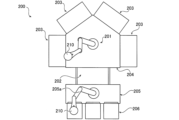
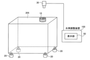
- FIG. 1 is a diagram showing a level adjustment device according to a first embodiment
- FIG. 1 is a diagram showing a configuration of a substrate processing system.
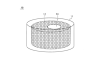
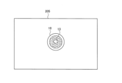
- FIG. 2 is a diagram showing a spirit level according to the first embodiment.
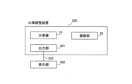
- 1 is a block diagram of a level adjustment device according to a first embodiment.
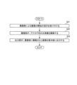
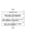
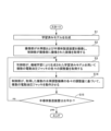
- FIG. 4 is a flow chart for explaining a level adjustment method according to the first embodiment.
- FIG. 13 is a diagram showing a level adjustment device and an EFEM according to a second embodiment.
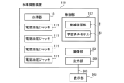
- FIG. 11 is a block diagram of a level adjustment device according to a second embodiment.
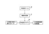
- 13A and 13B are diagrams for explaining a learning model for estimating the adjustment amount of the level adjustment mechanism according to the second embodiment.
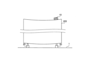
- FIG. 13 is a diagram showing a state in which the EFEM is bent.
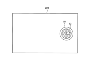
- FIG. 1 shows a spirit level placed on the EFEM.
- FIG. 11 is a diagram showing a spirit level disposed at a position different from that shown in FIG. 10 .
- FIG. 11 is a flow chart for explaining a level adjustment method according to a second embodiment.
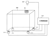
- FIG. 13 is a diagram showing a level adjustment device and an EFEM according to a third embodiment.
- FIG. 11 is a block diagram of a level adjustment device according to a third embodiment.
- FIG. 11 is a flow chart for explaining a level adjustment method according to a third embodiment.
- a level adjustment device 300 according to the first embodiment will be described. As shown in Fig. 1, the level adjustment device 300 is a device for assisting an operator in leveling an EFEM (Equipment Front End Module) 205 with respect to a floor surface 1.
- the EFEM 205 is an example of an object to be adjusted and a semiconductor manufacturing device.
- the substrate processing system 200 includes a substrate transport robot 201, a load lock unit 202, a plurality of processing module units 203, a transport chamber 204, and an EFEM 205.
- the substrate transport robot 201 is a horizontal articulated robot.
- the load lock unit 202 is a room for taking in and taking out the substrate 210.
- the substrate 210 is subjected to processes such as resist coating and etching.
- the substrate transport robot 201 is disposed in the transport chamber 204.
- a robot 205a for transporting the substrate 210 is disposed.
- Leveling device The following describes the configuration of the level adjustment device 300. As shown in FIG.
- the structure of the level 10 will be described.
- the level 10 is placed on the EFEM 205 and detects the inclination of the EFEM 205 with respect to the horizontal plane.
- the level 10 is an analog level 10 in which the inclination of the EFEM 205 with respect to the horizontal plane is visually confirmed.
- the level 10 has a liquid 12 contained in a container 11 and an air bubble 13 contained in the liquid 12.
- the air bubble 13 is located in the center of the container 11.
- the surface of the container 11 of the level 10 is made of a transparent material that allows the air bubble 13 inside to be seen, and the inside is a spherical surface with a very large curvature.
- the air bubble 13 moves to the center of the sphere.
- the air bubble 13 moves to a position shifted from the center of the sphere, and the air bubble 13 is located in a position shifted from the center of the container 11.
- the level adjustment mechanism 20 is, for example, an electric hydraulic jack, a manual jack, or an adjuster whose height is manually adjusted.
- an electric hydraulic jack the height of the electric hydraulic jack is adjusted by the amount of oil pumped out from the electric pump. For example, by turning on a switch, oil is pumped out to the electric pump, and the height of the electric hydraulic jack is adjusted.
- a manual jack the height of the manual jack is adjusted by the amount of oil pumped out by manually moving the handle up and down.
- the height of the adjuster is adjusted by manually rotating a nut portion that screws into a bolt portion of the adjuster.
- multiple level adjustment mechanisms 20 are arranged below the EFEM 205. For example, the level adjustment mechanisms 20 are arranged at each of the four corners below the EFEM 205.
- the configuration of the imaging unit 30 will be described.
- the imaging unit 30 is, for example, a two-dimensional camera.
- the imaging unit 30 images the spirit level 10 placed on the EFEM 205.
- the imaging unit 30 images the container 11, the liquid 12, and the air bubbles 13 of the spirit level 10.
- the imaging unit 30 may be disposed in a position where it can photograph the spirit level 10.
- the imaging unit 30 is disposed on the ceiling above the spirit level 10.
- the imaging unit 30 may also be disposed on a support member such as a stand that supports the imaging unit 30.
- the output unit 301 outputs the image of the spirit level 10 captured by the imaging unit 30 to the display unit 302.
- the output unit 301 is disposed in the imaging unit 30.
- the output unit 301 is also connected to the display unit 302 by wiring 303, for example, and outputs the image of the spirit level 10 captured by the imaging unit 30 to the display unit 302 via the wiring 303.
- the output unit 301 may also wirelessly output the image of the spirit level 10 captured by the imaging unit 30 to the display unit 302.
- the image captured by the imaging unit 30 may be a still image or a video.
- the display unit 302 is arranged separately from the level adjustment device 300.
- the display unit 302 may also be included in the level adjustment device 300.
- the display unit 302 is, for example, a liquid crystal display.
- the display unit 302 may also be arranged near the EFEM 205 or far away from the EFEM 205.
- the level adjustment method is performed using a level adjustment device 300 including the above-mentioned imaging unit 30 and output unit 301.
- the spirit level 10 is placed on the top surface of the EFEM 205 in advance by an operator.
- the imaging unit 30 is placed in advance by an operator in a position where it can photograph the spirit level 10.
- step S21 the level adjustment device 300 receives an instruction from the operator to start imaging using the imaging unit 30.
- step S22 the imaging unit 30 captures an image of the analog level 10, which allows the inclination of the EFEM 205 relative to the horizontal plane to be visually confirmed.
- step S23 the output unit 301 outputs the image of the spirit level 10 captured by the imaging unit 30 to the display unit 302. If the imaging unit 30 captures a still image, the operations of steps S21 to S23 are repeated. If the imaging unit 30 captures a video, the operations of steps S22 and S23 are repeated until the level adjustment device 300 receives an instruction to stop imaging by the imaging unit 30. While visually checking the image of the spirit level 10 displayed on the display unit 302, the operator manually adjusts the level adjustment mechanism 20 so that the EFEM 205 is horizontal.
- the level adjustment device 300 includes an analog level 10 that allows the inclination of the EFEM 205 relative to the horizontal plane to be visually confirmed.
- the analog level 10 has a relatively simple structure compared to a digital level, and is therefore smaller than a digital level.
- the level adjustment device 300 can be made smaller.
- the level adjustment device 300 also includes an imaging unit 30 that captures an image of the level 10, and an output unit 301 that outputs the image of the level 10 captured by the imaging unit 30 to a display unit 302, so that an operator can easily visually confirm the inclination of the EFEM 205 at a position separated from the EFEM 205 by checking the image of the level 10 displayed on the display unit 302.
- the analog level 10 does not need to be calibrated like the digital level 10.
- the analog level 10 is easier to handle than a digital level.
- the spirit level 10 has a liquid 12 contained in a container 11 and an air bubble 13 contained in the liquid 12, and the imaging unit 30 images the container 11, the liquid 12, and the air bubble 13 of the spirit level 10. This allows the operator to easily check the inclination of the EFEM 205 with respect to the horizontal plane based on the position of the air bubble 13 in the container 11 of the spirit level 10 displayed on the display unit 302.
- the spirit level 10 is disposed on the EFEM 205. This allows the size of the level adjustment device 300 for leveling the EFEM 205 to be reduced.
- the level adjustment device 100 is a device for assisting an operator in leveling an EFEM (Equipment Front End Module) 205 with respect to a floor surface 1.
- EFEM Equipment Front End Module
- the level adjustment device 100 includes a spirit level 10, a plurality of level adjustment mechanisms 20, an imaging unit 30, a control unit 40, and a display unit 50.
- the level adjustment device 100 is, for example, a device including an imaging unit 30, a display unit 50, and a control unit 40, such as a tablet terminal.
- the display unit 50 is an example of an adjustment amount display unit.
- the display unit 50 may also function as the display unit 302 on which an image of the spirit level 10 captured by the imaging unit 30 of the first embodiment is displayed, or a display unit 302 on which an image of the spirit level 10 captured by the imaging unit 30 is displayed may be disposed separately from the display unit 50.
- the configuration of the imaging unit 30 will be described.
- the image captured by the imaging unit 30 is transmitted to the control unit 40.
- the imaging unit 30 also captures the EFEM 205 as well as the spirit level 10.
- the control unit 40 then recognizes, for example, by image processing, the spirit level 10, the position of the air bubble 13 in the spirit level 10, the EFEM 205, and the position of the FEM 205 in which the spirit level 10 is located, based on the image captured by the imaging unit 30.
- control unit 40 includes, for example, a CPU (Central Processing Unit).
- the control unit 40 also includes memories such as RAM and ROM, and a storage unit such as a hard disk.
- the control unit 40 also includes a machine learning unit 41.
- the machine learning unit 41 generates a trained model 43 by machine learning based on input learning data 42.
- the machine learning unit 41 also generates the trained model 43 by using, for example, deep learning.
- the trained model 43 is generated by machine learning an image of the level 10 arranged on the EFEM 205.
- the trained model 43 is also generated by machine learning an image of the level 10 when the adjustment amount of at least one of the multiple level adjustment mechanisms 20 is changed.
- the imager 30 captures an image of the level 10 arranged on the EFEM 205 while changing the adjustment amount of the multiple level adjustment mechanisms 20 in various ways. Each captured image is linked to the adjustment amount of the level adjustment mechanism 20 at the time of capture.
- the change in the level of the EFEM 205 is not the same when one of the three level adjustment mechanisms 20 that support most of the weight of the EFEM 205 is changed as when one level adjustment mechanism 20 that does not bear weight is changed. For this reason, it is necessary to learn images of the level 10 when the adjustment amount of at least one of the multiple level adjustment mechanisms 20 is changed. Then, multiple images are input to the machine learning unit 41 as learning data 42 when the adjustment amount of the multiple level adjustment mechanisms 20 is changed in various ways.
- the machine learning unit 41 generates a trained model 43 by machine learning the learning data 42.
- the trained model 43 generated in this way, it is learned where the air bubble 13 of the level 10 placed on the EFEM 205 is located in the level 10 with respect to the adjustment amount of the level adjustment mechanism 20.
- the trained model 43 is generated by machine learning an image of the spirit level 10 placed on the EFEM 205 in a bent state. That is, the image of the spirit level 10 placed on the EFEM 205 in a bent state is captured by the imaging unit 30 while the adjustment amount of the multiple level adjustment mechanisms 20 is changed in various ways. That is, changing the adjustment amount of the level adjustment mechanisms 20 changes the weight balance of the EFEM 205, and therefore the bent state of the EFEM 205 changes. Therefore, the adjustment amount of the level adjustment mechanisms 20 and the inclination of the spirit level 10 do not have a simple proportional relationship. Therefore, it is necessary to train the EFEM 205 in a bent state.
- the control unit 40 acquires the adjustment amount of each of the multiple level adjustment mechanisms 20 based on the image of the level 10 by using the trained model 43 generated by machine learning. Specifically, the control unit 40 acquires the adjustment amount of each of the multiple level adjustment mechanisms 20 based on the image of the level 10 captured by the imaging unit 30 by using the trained model 43. For example, as shown in FIG. 10 and FIG. 11, the level 10 arranged on the upper surface of the EFEM 205 is imaged by the imaging unit 30. In addition, the imaging unit 30 captures not only the level 10 but also the EFEM 205. The captured image is then input to the trained model 43.
- the trained model 43 estimates the adjustment amount of each of the multiple level adjustment mechanisms 20 to level the EFEM 205 based on the input image.
- the adjustment amount of the level adjustment mechanism 20 is estimated for each of the multiple level adjustment mechanisms 20.
- the control unit 40 acquires the adjustment amount of the level adjustment mechanism 20 from the trained model 43. If the level adjustment mechanism 20 is an electric hydraulic jack, the time or number of times that a switch for adjusting the amount of oil pumped from the electric pump is turned on is acquired as the adjustment amount. If the level adjustment mechanism 20 is a manual jack, the number of times the handle is moved up and down is acquired as the adjustment amount. If the level adjustment mechanism 20 is an adjuster, the number of rotations of the nut part of the adjuster is acquired as the adjustment amount.
- the display unit 50 is, for example, a liquid crystal display.
- the display unit 50 may be attached to the housing of the level adjustment device 100, or may be disposed separately from the housing of the level adjustment device 100.
- the display unit 50 displays the adjustment amount of each of the multiple level adjustment mechanisms 20 acquired by the control unit 40. That is, the control unit 40 executes a process of displaying the acquired adjustment amount of each of the multiple level adjustment mechanisms 20 on the display unit 50. Then, the operator adjusts the multiple level adjustment mechanisms 20 based on the adjustment amount of each of the multiple level adjustment mechanisms 20 displayed on the display unit 50.
- the level adjustment method is a method for leveling the EFEM 205 by adjusting a plurality of level adjustment mechanisms 20.
- the adjustment of the level adjustment mechanisms 20 is performed by an operator.
- a trained model 43 is generated.
- the trained model 43 is generated by machine learning data related to the inclination of the EFEM 205 detected by the level 10 when the level 10 is placed on the EFEM 205.
- training data 42 for generating the trained model 43 is prepared.
- the training data 42 is a plurality of images capturing the level 10 and the EFEM 205 captured by the imaging unit 30 when the adjustment amounts of the plurality of level adjustment mechanisms 20 are changed in various ways.
- the worker then inputs the training data 42 to the machine learning unit 41, which causes the machine learning unit 41 to generate the trained model 43.
- the level adjustment mechanism 20 is floating above the floor surface 1
- the EFEM 205 may be leveled by the level adjustment mechanisms 20 arranged at three corners, and the level adjustment mechanism 20 arranged at the remaining corner may be floating above the floor surface 1.
- the trained model 43 has also learned the adjustment amount of the level adjustment mechanism 20 in a state where the EFEM 205 is leveled by the level adjustment mechanisms 20 arranged at three corners, and the level adjustment mechanism 20 arranged at the remaining corner is floating above the floor surface 1. This prevents the trained model 43 from estimating the adjustment amount of the level adjustment mechanism 20 such that the EFEM 205 is leveled by the level adjustment mechanisms 20 arranged at three corners, and the level adjustment mechanism 20 arranged at the remaining corner is floating above the floor surface 1.
- step S2 the control unit 40 acquires data regarding the inclination of the EFEM 205 with respect to the horizontal plane from the spirit level 10 placed on the EFEM 205. Specifically, the worker places the spirit level 10 on the EFEM 205. The imaging unit 30 then captures an image of the spirit level 10 together with the EFEM 205. The control unit 40 acquires an image of the spirit level 10 and the EFEM 205 from the imaging unit 30 as data regarding the inclination of the EFEM 205 with respect to the horizontal plane.
- step S3 the control unit 40 uses the trained model 43 generated by machine learning to obtain the adjustment amount for each of the multiple level adjustment mechanisms 20 based on data regarding the tilt of the EFEM 205 detected by the spirit level 10. Specifically, the control unit 40 inputs the images of the spirit level 10 and EFEM 205 obtained in step S2 to the trained model 43. Then, based on the input images, the trained model 43 estimates the adjustment amount for each of the multiple level adjustment mechanisms 20 to level the EFEM 205, and the control unit 40 obtains the estimated adjustment amount for each of the multiple level adjustment mechanisms 20.
- step S4 the control unit 40 executes a process of displaying the acquired adjustment amounts of each of the multiple level adjustment mechanisms 20 on the display unit 50.
- the worker adjusts the multiple level adjustment mechanisms 20 based on the adjustment amounts of each of the multiple level adjustment mechanisms 20 displayed on the display unit 50. If the EFEM 205 is not level even after adjusting the multiple level adjustment mechanisms 20, the operations from steps S2 to S4 are repeated. For example, the worker operates the level adjustment device 100 to repeat the operations from steps S2 to S4 while checking the spirit level 10.
- a plurality of level adjustment mechanisms 20 are disposed below the EFEM 205.
- the level adjustment device 100 includes a control unit 40 that acquires the adjustment amount of each of the plurality of level adjustment mechanisms 20 based on an image of the spirit level 10 disposed on the EFEM 205 captured by the imaging unit 30.
- the display unit 50 displays the adjustment amount of each of the plurality of level adjustment mechanisms 20 acquired by the control unit 40. This allows an operator to easily adjust the plurality of level adjustment mechanisms 20 based on the adjustment amount of each of the plurality of level adjustment mechanisms 20 displayed on the display unit 50. Furthermore, unlike a case in which an operator visually checks the spirit level 10 and another operator adjusts the plurality of level adjustment mechanisms 20, the EFEM 205 can be leveled by one operator.
- the control unit 40 uses a trained model 43 generated by machine learning to obtain the adjustment amount for each of the multiple level adjustment mechanisms 20 based on the image of the spirit level 10 captured by the imaging unit 30.
- machine learning can learn to associate the actual state of the EFEM 205, such as a state in which the EFEM 205 is bent, with the adjustment amounts for the multiple level adjustment mechanisms 20, and therefore, by using the trained model 43 thus trained, it is possible to accurately obtain the adjustment amount for positioning the EFEM 205 horizontally, taking into account the actual state of the EFEM 205.
- the trained model 43 is generated by machine learning an image of the spirit level 10 placed in the EFEM 205.
- an image of the spirit level 10 in a state in which the spirit level 10 is actually placed in the EFEM 205 is machine learned, so the trained model 43 becomes a trained model 43 that takes into account the actual state of the EFEM 205.
- the trained model 43 by simply placing the spirit level 10 actually in the EFEM 205, it is possible to easily generate a trained model 43 that takes into account the actual state of the EFEM 205.
- the trained model 43 is generated by machine learning an image of the spirit level 10 placed on the EFEM 205 in a deflected state. This makes it possible to generate a trained model 43 that takes into account changes in the deflection of the EFEM 205 caused by changes in the adjustment amount of the level adjustment mechanism 20.
- the trained model 43 is generated by machine learning images of the spirit level 10 captured by the imaging unit 30 when the adjustment amount of at least one of the multiple level adjustment mechanisms 20 is changed. This also learns images of the spirit level 10 when the level adjustment mechanism 20 is adjusted when the weight of the EFEM 205 applied to the multiple level adjustment mechanisms 20 is not uniform, making it possible to accurately learn the adjustment amount of the EFEM 205.
- a level adjustment device 110 according to the third embodiment will be described.
- an electric hydraulic jack 111 serving as a level adjustment mechanism is controlled by a control unit 112.
- the level adjustment device 110 has a plurality of electric hydraulic jacks 111 arranged as a level adjustment mechanism. Also, as shown in FIG. 14, the output unit 301 of the level adjustment device 110 outputs an image of the spirit level 10 captured by the imaging unit 30 to the display unit 302 via wiring 303. Note that the display unit 302 may be included in the level adjustment device 110.
- step S14 the control unit 40 operates the multiple electric hydraulic jacks 111 based on the acquired adjustment amounts for each of the multiple electric hydraulic jacks 111, thereby adjusting the inclination of the EFEM 205 so that the EFEM 205 is aligned with the horizontal surface.
- step S15 the control unit 40 determines whether the EFEM 205 is level. Specifically, after adjusting the multiple electric hydraulic jacks 111, the control unit 40 causes the imaging unit 30 to capture an image of the spirit level 10, and determines whether the EFEM 205 is level based on the image captured by the imaging unit 30. If the answer is no in step S15, the process returns to step S3. If the answer is yes in step S15, the level adjustment operation by the control unit 40 ends.
- the control unit 112 adjusts the inclination of the EFEM 205 so that the EFEM 205 is aligned with the horizontal plane by operating the multiple electric hydraulic jacks 111 based on the acquired adjustment amounts of each of the multiple electric hydraulic jacks 111. This eliminates the need for an operator to manually adjust the multiple electric hydraulic jacks 111, thereby reducing the operator's workload.
- an analog level 10 having a container 11, liquid 12 and air bubble 13 is applied to the present disclosure, but the present disclosure is not limited to this.
- an analog level 10 other than an analog level 10 having a container 11, liquid 12 and air bubble 13 may be applied to the present disclosure.
- the EFEM 205 is applied as the object to be adjusted according to the present disclosure, but the present disclosure is not limited to this.
- the present disclosure may also be applied to an object to be adjusted other than the EFEM 205.
- the level adjustment device 300 may be a device for assisting an operator in leveling the transport chamber 204 with respect to the floor surface 1.
- the level adjustment device 100 includes a machine learning unit 41, but the present disclosure is not limited to this.
- the trained model 43 may be generated by a machine learning unit 41 arranged in an external device other than the level adjustment device 100. The same applies to the third embodiment.
- control unit 40 obtains the adjustment amount of each of the multiple level adjustment mechanisms 20 based on an image of the spirit level 10 by using the trained model 43 generated by machine learning, but the present disclosure is not limited to this.
- control unit 40 may obtain the adjustment amount of each of the multiple level adjustment mechanisms 20 by image processing of the image of the spirit level 10 without using the trained model 43.
- the level adjustment mechanisms 20 are disposed at each of the four lower corners of the EFEM 205, but the present disclosure is not limited to this.
- the level adjustment mechanisms 20 may be disposed at the center in addition to the four lower corners of the EFEM 205.
- the number of level adjustment mechanisms 20 may also be one, two, or three. The same applies to the third embodiment.
- the output unit 301 outputs an image of the spirit level 10 captured by the imaging unit 30 to the display unit 302, but the present disclosure is not limited to this.
- the output unit 301 may output an image of the spirit level 10 to a device other than the display unit 302.
- the electric hydraulic jacks 111 are controlled by the control unit 112 as in the third embodiment, it is possible to determine whether or not the electric hydraulic jacks 111 are floating above the floor surface 1. Specifically, when the electric hydraulic jacks 111 are arranged at the four corners below the EFEM 205, the EFEM 205 can be leveled by three of the electric hydraulic jacks 111 arranged at the four corners. In this case, the remaining electric hydraulic jack 111 may be floating above the floor surface 1. Therefore, with the EFEM 205 leveled, the control unit 40 increases the height of the electric hydraulic jacks 111 arranged at the four corners one by one, and the imaging unit 30 images the spirit level 10.
- control unit 40 determines, based on the image captured by the imaging unit 30, that the horizontal state of the EFEM 205 is maintained even if the height of the electric hydraulic jack 111 is increased, the control unit 40 can determine that the electric hydraulic jack 111 is floating above the floor surface 1. This makes it possible to prevent the EFEM 205 from being placed in an unstable state in which the electric hydraulic jack 111 placed in one corner is floating above the floor surface 1.
- circuits or processing circuits including general purpose processors, special purpose processors, integrated circuits, ASICs (Application Specific Integrated Circuits), conventional circuits, and/or combinations thereof, configured or programmed to perform the disclosed functions.
- Processors are considered processing circuits or circuits because they include transistors and other circuits.
- a circuit, unit, or means is hardware that performs the recited functions or hardware that is programmed to perform the recited functions.
- the hardware may be hardware disclosed herein or other known hardware that is programmed or configured to perform the recited functions. Where the hardware is a processor, which is considered a type of circuit, the circuit, means, or unit is a combination of hardware and software, and the software is used to configure the hardware and/or the processor.
- (Aspect 1) An analog level that visually checks the inclination of the object to be adjusted relative to a horizontal plane; An imaging unit that images the level; and an output unit that outputs an image of the spirit level captured by the imaging unit.
- the level includes a liquid contained in a container and an air bubble contained in the liquid, 2.
- a level adjustment mechanism is disposed on the object to be adjusted, A control unit that acquires an adjustment amount of the level adjustment mechanism based on an image of the spirit level placed on the object to be adjusted captured by the imaging unit.
- the control unit acquires the adjustment amount of the level adjustment mechanism by using a trained model that inputs an image of the spirit level placed on the object to be adjusted captured by the imaging unit and outputs the adjustment amount of the level adjustment mechanism.
- the level adjustment mechanism is provided in plurality, A level adjustment device as described in aspect 5 or aspect 6, wherein the trained model is generated by machine learning an image of the spirit level captured by the imaging unit when the adjustment amount of at least one of the multiple level adjustment mechanisms is changed.
- the plurality of level adjustment mechanisms are disposed at four corners below the object to be adjusted.
- the control unit identifies a level adjustment mechanism that is floating above the floor surface based on an image of the spirit level captured by the imaging unit when the adjustment amount of the level adjustment mechanism located in one corner is changed.
- the level adjustment mechanism includes an electric hydraulic jack, A level adjustment device as described in any one of aspects 3 to 8, wherein the control unit adjusts the inclination of the object to be adjusted so that the object is aligned with a horizontal plane by operating the electric hydraulic jack based on the adjustment amount of each of the acquired level adjustment mechanisms.
- Aspect 11 Aspect 11. The level adjustment device according to any one of aspects 1 to 10, wherein the output unit outputs an image of the level captured by the imaging unit to a display unit.
- a level adjustment method for a level adjustment device including an analog level, an imaging unit, and an output unit, comprising: The imaging unit images the analog level gauge, which allows the inclination of the object to be adjusted relative to a horizontal plane to be visually confirmed; The output unit outputs an image of the spirit level captured by the imaging unit.
Landscapes
- Physics & Mathematics (AREA)
- Engineering & Computer Science (AREA)
- General Physics & Mathematics (AREA)
- Radar, Positioning & Navigation (AREA)
- Remote Sensing (AREA)
- Measurement Of Levels Of Liquids Or Fluent Solid Materials (AREA)
- Testing, Inspecting, Measuring Of Stereoscopic Televisions And Televisions (AREA)
- Container, Conveyance, Adherence, Positioning, Of Wafer (AREA)
- Exposure Of Semiconductors, Excluding Electron Or Ion Beam Exposure (AREA)
- Machine Tool Units (AREA)
Abstract
この水準調整装置(300)は、被調整物(205)の水平面に対する傾きが目視によって確認されるアナログ式の水準器(10)と、水準器(10)を撮像する撮像部(30)と、撮像部(30)に撮像された水準器(10)の画像を出力する出力部(301)と、を備える。
Description
この開示は、水準調整装置および水準調整方法の制御方法に関する。
従来、被調整物を床面に対して水平に設置するための水準調整装置が開示されている。特許第6724622号には、被調整物としての半導体製造装置の水準を調整する際において、作業者を支援する水平設置支援装置が開示されている。特許第6724622号の水平設置支援装置は、水準計測器と、データ処理部と、表示部と、を備えている。特許第6724622号の水平設置支援装置では、デジタル式の水準計測器が半導体製造装置に載置されており、デジタル式の水準計測器が半導体製造装置の傾きを検出する。デジタル式の水準計測器が検出した傾きのデータは、半導体製造装置と離間した位置に配置されているデータ処理部に無線により送信される。また、半導体製造装置の下面には、複数の脚部が配置されている。脚部は、アジャスタを含んでおり、作業者によりアジャスタが回転されることにより、脚部の高さが変更される。データ処理部は、デジタル式の水準計測器により検出された半導体製造装置の傾きのデータに基づいて、半導体製造装置が水平になるための、脚部のアジャスタの回転数を算出する。
しかしながら、特許第6724622号に開示されているデジタル式の水準計測器は、構造が比較的複雑であるため大型になる。そこで、水準調整装置の小型化を図ることが望まれている。
この開示は、上記のような課題を解決するためになされたものであり、この開示の1つの目的は、水準調整装置の小型化を図ることが可能な水準調整装置および水準調整方法を提供することである。
この開示の第1の局面による水準調整装置は、被調整物の水平面に対する傾きが目視によって確認されるアナログ式の水準器と、水準器を撮像する撮像部と、撮像部に撮像された水準器の画像を出力する出力部と、を備える。
この開示の第1の局面による水準調整装置は、上記のように、水準調整装置は、被調整物の水平面に対する傾きが目視によって確認されるアナログ式の水準器を備える。これにより、アナログ式の水準器は、デジタル式の水準器と比べて構造が比較的簡素なので、デジタル式の水準器と比べて小型である。その結果、水準調整装置の小型化を図ることができる。また、第1の局面による水準調整装置は、水準器を撮像する撮像部と、撮像部に撮像された水準器の画像を出力する出力部と、を備えるので、作業者が、表示部などに出力された水準器の画像を確認することにより、被調整物から離間した位置において被調整物の傾きを容易に確認することができる。また、アナログ式の水準器は、デジタルの水準器に比べて取り扱いが容易である。また、アナログ式の水準器は、デジタル式の水準器のように校正を行う必要もない。
この開示の第2の局面による水準調整方法は、アナログ式の水準器と撮像部と出力部とを備える水準調整装置の水準調整方法であって、撮像部が、被調整物の水平面に対する傾きが目視によって確認されるアナログ式の水準器を撮像することと、出力部が、撮像部に撮像された水準器の画像を出力することと、を備える。
この開示の第2の局面による水準調整方法において、上記のように、被調整物の水平面に対する傾きが目視によって確認されるアナログ式の水準器が用いられる。これにより、アナログ式の水準器は、デジタル式の水準器と比べて構造が比較的簡素なので、デジタル式の水準器と比べて小型である。その結果、水準調整装置の小型化を図ることが可能な水準調整方法を提供することができる。また。第2の局面による水準調整方法は、出力部が、撮像部に撮像された水準器の画像を出力することを備えるので、作業者が、表示部などに出力された水準器の画像を確認することにより、被調整物から離間した位置において被調整物の傾きを容易に確認することができる。また、アナログ式の水準器は、デジタルの水準器に比べて取り扱いが容易である。また、アナログ式の水準器は、デジタル式の水準器のように校正を行う必要もない。
本開示によれば、水準調整装置の小型化を図りながら、被調整物から離間した位置において被調整物の傾きを確認することができる。
以下、本開示を具体化した本開示の実施形態を図面に基づいて説明する。
[第1実施形態]
第1実施形態による水準調整装置300について説明する。図1に示すように、水準調整装置300は、作業者が、EFEM(Equipment Front End Module)205を床面1に対して水平にするための作業を支援するための装置である。なお、EFEM205は、被調整物および半導体製造装置の一例である。
第1実施形態による水準調整装置300について説明する。図1に示すように、水準調整装置300は、作業者が、EFEM(Equipment Front End Module)205を床面1に対して水平にするための作業を支援するための装置である。なお、EFEM205は、被調整物および半導体製造装置の一例である。
(基板処理システム)
EFEM205が含まれる基板処理システム200の構成について説明する。図2に示すように、基板処理システム200は、基板搬送ロボット201、ロードロック部202、複数の処理モジュール部203、搬送室204およびEFEM205を備えている。基板搬送ロボット201は、水平多関節ロボットである。ロードロック部202は、基板210の取入れ、および、取出しを行うための部屋である。処理モジュール部203では、基板210に対して、レジストの塗布や、エッヂングなどの処理が行われる。搬送室204には、基板搬送ロボット201が配置される。EFEM205には、基板210を搬送するロボット205aが配置されている。
EFEM205が含まれる基板処理システム200の構成について説明する。図2に示すように、基板処理システム200は、基板搬送ロボット201、ロードロック部202、複数の処理モジュール部203、搬送室204およびEFEM205を備えている。基板搬送ロボット201は、水平多関節ロボットである。ロードロック部202は、基板210の取入れ、および、取出しを行うための部屋である。処理モジュール部203では、基板210に対して、レジストの塗布や、エッヂングなどの処理が行われる。搬送室204には、基板搬送ロボット201が配置される。EFEM205には、基板210を搬送するロボット205aが配置されている。
(水準調整装置)
水準調整装置300の構成について説明する。図1に示すように、水準調整装置300は、水準器10と、撮像部30と、出力部301と、を備えている。
水準調整装置300の構成について説明する。図1に示すように、水準調整装置300は、水準器10と、撮像部30と、出力部301と、を備えている。
水準器10の構成について説明する。水準器10は、EFEM205に載置され、EFEM205の水平面に対する傾きを検出する。水準器10は、EFEM205の水平面に対する傾きが目視によって確認されるアナログ式の水準器10である。図3に示すように、第1実施形態では、水準器10は、容器11中に収容された液体12と、液体12に含まれる気泡13とを有する。水準器10が水平面に載置されている場合には、気泡13は容器11の中央部に位置する。具体的には、水準器10の容器11の表面は、透明で中の気泡13が見える素材でできており、内側は非常に大きな曲率の球面になっている。このため、水準器10が水平面に配置されている場合、気泡13が球面の一番高い中央部に移動する。一方、水準器10が傾斜面に配置されている場合、気泡13が球面の一番高い中央部からずれた位置に移動するため、気泡13は容器11の中央部からずれた位置に位置する。
水準調整機構20の構成について説明する。図1に示すように、水準調整機構20は、たとえば、電動油圧ジャッキ、手動式のジャッキ、または、手動で高さが調整されるアジャスタなどである。電動油圧ジャッキでは、電動ポンプから送り出される油の量によって電動油圧ジャッキの高さが調整される。たとえば、スイッチをオンすることにより、電動ポンプに油が送り出され、電動油圧ジャッキの高さが調整される。手動式のジャッキでは、手動によりハンドルが上下されることにより送り出される油の量によって手動式のジャッキの高さが調整される。アジャスタでは、アジャスタのボルト部に螺号するナット部が手動により回転されることにより、アジャスタの高さが調整される。また、水準調整機構20は、EFEM205の下方に複数配置されている。たとえば、水準調整機構20は、EFEM205の下方の4隅に各々配置されている。
撮像部30の構成について説明する。撮像部30は、たとえば、2次元のカメラである。撮像部30は、EFEM205に配置された水準器10を撮像する。具体的には、撮像部30は、水準器10の、容器11、液体12および気泡13を撮像する。また、撮像部30は、水準器10を撮影可能な位置に配置されていればよい。たとえば、撮像部30は、水準器10の上方の天井に配置されている。また、撮像部30が、撮像部30を支持するスタンドのような支持部材に配置されていてもよい。
出力部301の構成について説明する。出力部301は、撮像部30に撮像された水準器10の画像を表示部302に出力する。たとえば、出力部301は、撮像部30に配置されている。また、出力部301は、たとえば、表示部302に配線303によって接続されており、撮像部30に撮像された水準器10の画像を、配線303を介して表示部302に出力する。また、出力部301は、撮像部30に撮像された水準器10の画像を、無線によって表示部302に出力してもよい。また、撮像部30によって撮像される画像は、静止画でもよいし、動画でもよい。
表示部302の構成について説明する。図4に示すように、表示部302は、水準調整装置300と別個に配置されている。なお、表示部302が、水準調整装置300に含まれていてもよい。表示部302は、たとえば、液晶ディスプレイである。また、表示部302は、EFEM205の近傍に配置されていてもよいし、EFEM205の遠方に配置されていてもよい。
次に、図5を参照して、第1実施形態の水準調整方法について説明する。水準調整方法は、上記の撮像部30と出力部301とを備える水準調整装置300を用いて実行される。水準器10は、予め作業者によって、EFEM205の上面に配置されている。また、撮像部30は、予め作業者によって、水準器10を撮影可能な位置に配置されている。
ステップS21において、水準調整装置300は、作業者からの撮像部30による撮像の開始の指示を受け付ける。
ステップS22において、撮像部30は、EFEM205の水平面に対する傾きが目視によって確認されるアナログ式の水準器10を撮像する。
ステップS23において、出力部301は、撮像部30に撮像された水準器10の画像を表示部302に出力する。なお、撮像部30が静止画を撮像する場合、ステップS21~S23の動作が繰り返される。また、撮像部30が動画を撮像する場合、撮像部30による撮像の停止の指示が水準調整装置300により受け付けられるまで、ステップS22およびS23の動作が繰り返される。作業者は、表示部302に表示された水準器10の画像を視認しながら、EFEM205が水平になるように水準調整機構20を手動で調整する。
[第1実施形態の効果]
水準調整装置300は、EFEM205の水平面に対する傾きが目視によって確認されるアナログ式の水準器10を備える。これにより、アナログ式の水準器10は、デジタル式の水準器と比べて構造が比較的簡素なので、デジタル式の水準器と比べて小型である。その結果、水準調整装置300の小型化を図ることができる。また、水準調整装置300は、水準器10を撮像する撮像部30と、撮像部30に撮像された水準器10の画像を表示部302に出力する出力部301と、を備えるので、作業者は、表示部302に表示された水準器10の画像を確認することにより、EFEM205から離間した位置においてEFEM205の傾きを視覚的に容易に確認することができる。また、アナログ式の水準器10は、デジタル式の水準器10のように校正を行う必要もない。また、アナログ式の水準器10は、デジタルの水準器に比べて取り扱いが容易である。
水準調整装置300は、EFEM205の水平面に対する傾きが目視によって確認されるアナログ式の水準器10を備える。これにより、アナログ式の水準器10は、デジタル式の水準器と比べて構造が比較的簡素なので、デジタル式の水準器と比べて小型である。その結果、水準調整装置300の小型化を図ることができる。また、水準調整装置300は、水準器10を撮像する撮像部30と、撮像部30に撮像された水準器10の画像を表示部302に出力する出力部301と、を備えるので、作業者は、表示部302に表示された水準器10の画像を確認することにより、EFEM205から離間した位置においてEFEM205の傾きを視覚的に容易に確認することができる。また、アナログ式の水準器10は、デジタル式の水準器10のように校正を行う必要もない。また、アナログ式の水準器10は、デジタルの水準器に比べて取り扱いが容易である。
水準器10は、容器11中に収容された液体12と、液体12に含まれる気泡13とを有し、撮像部30は、水準器10の、容器11、液体12および気泡13を撮像する。これにより、作業者が、表示部302に表示された水準器10の容器11における気泡13の位置に基づいて、EFEM205の水平面に対する傾きを容易に確認することができる。
水準器10は、EFEM205に配置されている。これにより、EFEM205を水平にするための水準調整装置300の小型化を図ることができる。
[第2実施形態]
第2実施形態による水準調整装置100について説明する。図6に示すように、水準調整装置100は、作業者が、EFEM(Equipment Front End Module)205を床面1に対して水平にするための作業を支援するための装置である。
第2実施形態による水準調整装置100について説明する。図6に示すように、水準調整装置100は、作業者が、EFEM(Equipment Front End Module)205を床面1に対して水平にするための作業を支援するための装置である。
(水準調整装置)
水準調整装置100の構成について説明する。図7に示すように、水準調整装置100は、水準器10と、複数の水準調整機構20と、撮像部30と、制御部40と、表示部50と、を備えている。なお、水準調整装置100は、たとえば、タブレット端末のような、撮像部30と表示部50と制御部40とを備える機器である。なお、表示部50は、調整量表示部の一例である。また、表示部50は、上記第1実施形態の撮像部30に撮像された水準器10の画像が表示される表示部302を兼ねていてもよいし、表示部50とは別個に撮像部30に撮像された水準器10の画像が表示される表示部302が配置されていてもよい。
水準調整装置100の構成について説明する。図7に示すように、水準調整装置100は、水準器10と、複数の水準調整機構20と、撮像部30と、制御部40と、表示部50と、を備えている。なお、水準調整装置100は、たとえば、タブレット端末のような、撮像部30と表示部50と制御部40とを備える機器である。なお、表示部50は、調整量表示部の一例である。また、表示部50は、上記第1実施形態の撮像部30に撮像された水準器10の画像が表示される表示部302を兼ねていてもよいし、表示部50とは別個に撮像部30に撮像された水準器10の画像が表示される表示部302が配置されていてもよい。
撮像部30の構成について説明する。第2実施形態では、撮像部30により撮像された画像は、制御部40に送信される。また、撮像部30は、水準器10とともにEFEM205も撮像する。そして、制御部40は、たとえば、画像処理により、撮像部30に撮像された画像に基づいて、水準器10、水準器10における気泡13の位置、EFEM205、および、FEM205のいずれの位置に水準器10が配置されているのかを認識する。
制御部40の構成について説明する。図7に示すように、制御部40は、たとえば、CPU(Central Processing Unit)を含む。また、制御部40は、RAMおよびROMなどのメモリや、ハードディスクなどの記憶部も含む。また、制御部40は、機械学習部41を含む。機械学習部41は、入力された学習用データ42に基づいて、機械学習により、学習済みモデル43を生成する。また、機械学習部41は、たとえば、深層学習を用いて学習済みモデル43を生成する。
学習済みモデル43の生成方法について具体的に説明する。図8に示すように、第2実施形態では、学習済みモデル43は、EFEM205に配置された水準器10の画像が機械学習されることにより生成されている。また、学習済みモデル43は、複数の水準調整機構20のうちの少なくとも1つの調整量を変化させた場合の水準器10の画像が機械学習されることにより生成されている。具体的には、複数の水準調整機構20の調整量を様々に変化させながら、撮像部30によりEFEM205に配置された水準器10が撮像される。また、撮像された各画像と、撮像された際の水準調整機構20の調整量とは紐づけられている。たとえば、EFEM205に4つの水準調整機構20が配置されている場合、EFEM205の大部分の重量は3つの水準調整機構20で支えられており、1つの水準調整機構20にはほとんど重量が掛かっていない状態があり得る。その時、EFEM205の大部分の重量を支える3つの水準調整機構20のうちのどれかを変化させた時と、重量のかかっていない1つの水準調整機構20を変化させた時とではEFEM205水準の変化が同じではない。このため、複数の水準調整機構20のうちの少なくとも1つの調整量を変化させた場合の水準器10の画像を学習する必要がある。そして、機械学習部41には、複数の水準調整機構20の調整量を様々に変化させた際に複数の画像が学習用データ42として入力される。機械学習部41は、学習用データ42を機械学習することにより学習済みモデル43を生成する。このように生成された学習済みモデル43では、水準調整機構20の調整量に対して、EFEM205に配置された水準器10の気泡13が、水準器10においてどの位置に位置するのかが学習されている。
また、図9に示すように、第2実施形態では、学習済みモデル43は、撓んだ状態のEFEM205に配置された水準器10の画像が機械学習されることにより生成されている。すなわち、複数の水準調整機構20の調整量を様々に変化させながら、撓んだ状態のEFEM205に配置された水準器10が撮像部30により撮像される。つまり、水準調整機構20の調整量を変化させることによりEFEM205の重量のバランスが変わるため、EFEM205の撓んだ状態が変化する。そのため水準調整機構20の調整量と水準器10の傾きは単純な比例関係にならない。そこで、撓んだ状態のEFEM205を学習する必要がある。
水準調整機構20の調整量を取得するための制御部40の動作について説明する。図8に示すように、第2実施形態では、制御部40は、機械学習により生成された学習済みモデル43を用いることによって、水準器10の画像に基づいて、複数の水準調整機構20の各々の調整量を取得する。具体的には、制御部40は、学習済みモデル43を用いることによって、撮像部30に撮像された水準器10の画像に基づいて、複数の水準調整機構20の各々の調整量を取得する。たとえば、図10および図11に示すような、EFEM205の上面に配置されている水準器10が撮像部30により撮像される。また、撮像部30は、水準器10だけでなくEFEM205も撮像する。そして、撮像された画像が、学習済みモデル43に入力される。学習済みモデル43は、入力された画像に基づいて、EFEM205を水平にするための複数の水準調整機構20の各々の調整量を推定する。水準調整機構20の調整量は、複数の水準調整機構20の各々に対して推定される。制御部40は、学習済みモデル43から水準調整機構20の調整量を取得する。水準調整機構20が電動油圧ジャッキの場合、電動ポンプから送り出される油の量を調整するためのスイッチをオンする時間や回数などが調整量として取得される。また、水準調整機構20が手動式のジャッキの場合、ハンドルを上下する回数が調整量として取得される。水準調整機構20がアジャスタの場合、アジャスタのナット部の回転数が調整量として取得される。
表示部50の構成について説明する。図6に示すように、表示部50は、たとえば、液晶ディスプレイなどである。表示部50は、水準調整装置100の筐体に取り付けられていてもよいし、水準調整装置100の筐体とは別個に配置されていてもよい。第2実施形態では、表示部50は、制御部40が取得した複数の水準調整機構20の各々の調整量を表示する。すなわち、制御部40は、取得した複数の水準調整機構20の各々の調整量を表示部50に表示させる処理を実行する。そして、作業者は、表示部50に表示された複数の水準調整機構20の各々の調整量に基づいて、複数の水準調整機構20を調整する。
次に、図12を参照して、第2実施形態の水準調整方法について説明する。水準調整方法は、複数の水準調整機構20を調整することにより、EFEM205を水平にするための方法である。また、第2実施形態では、水準調整機構20の調整は、作業者により実行される。
ステップS1において、学習済みモデル43が生成される。第2実施形態では、EFEM205に水準器10が配置された状態での水準器10が検出したEFEM205の傾きに関するデータを機械学習することにより学習済みモデル43が生成される。具体的には、学習済みモデル43を生成するための学習用データ42が準備される。学習用データ42は、複数の水準調整機構20の調整量を様々に変化させた際に撮像部30により撮像された、水準器10およびEFEM205が映っている複数の画像である。そして、作業者により学習用データ42が機械学習部41に入力されることにより、機械学習部41は、学習済みモデル43を生成する。
水準調整機構20が床面1から浮いている場合について説明する。EFEM205の4隅に水準調整機構20が配置されている場合、3隅に配置された水準調整機構20によってEFEM205が水平にされ、残りの1隅に配置された水準調整機構20が床面1から浮いている場合がある。そこで、学習済みモデル43は、3隅に配置された水準調整機構20によってEFEM205が水平にされ、残りの1隅に配置された水準調整機構20が床面1から浮いている状態での水準調整機構20の調整量も学習されている。これにより、学習済みモデル43が、3隅に配置された水準調整機構20によってEFEM205が水平にされ、残りの1隅に配置された水準調整機構20が床面1から浮くような水準調整機構20の調整量を推定することが抑制される。
ステップS2において、制御部40は、EFEM205に載置される水準器10から、EFEM205の水平面に対する傾きに関するデータを取得する。具体的には、作業者が、EFEM205に水準器10を載置する。そして、撮像部30は、水準器10をEFEM205とともに撮像する。制御部40は、撮像部30からEFEM205の水平面に対する傾きに関するデータとして、水準器10およびEFEM205が撮像された画像を取得する。
ステップS3において、制御部40は、機械学習により生成された学習済みモデル43を用いることによって、水準器10が検出したEFEM205の傾きに関するデータに基づいて、複数の水準調整機構20の各々の調整量を取得する。具体的には、制御部40は、ステップS2において取得した水準器10およびEFEM205が撮像された画像を、学習済みモデル43に入力する。そして、学習済みモデル43は、入力された画像に基づいて、EFEM205を水平にするための複数の水準調整機構20の各々の調整量を推定し、制御部40は、推定された複数の水準調整機構20の各々の調整量を取得する。
ステップS4において、制御部40は、取得した複数の水準調整機構20の各々の調整量を、表示部50に表示させる処理を実行する。作業者は、表示部50に表示された複数の水準調整機構20の各々の調整量に基づいて、複数の水準調整機構20を調整する。複数の水準調整機構20を調整した後でも、EFEM205が水平にならない場合、ステップS2からS4までの動作が繰り返される。たとえば、作業者が水準器10を確認しながらステップS2からS4までの動作を繰り返すように水準調整装置100を操作する。
[第2実施形態の効果]
EFEM205の下方には、複数の水準調整機構20が配置されている。水準調整装置100は、撮像部30に撮像されたEFEM205に配置された水準器10の画像に基づいて、複数の水準調整機構20の各々の調整量を取得する制御部40を備える。表示部50は、制御部40が取得した複数の水準調整機構20の各々の調整量を表示する。これにより、作業者は、表示部50に表示された複数の水準調整機構20の各々の調整量に基づいて、複数の水準調整機構20を容易に調整できる。また、水準器10を作業者が視認し、複数の水準調整機構20を別の作業者が調整する場合と異なり、一人の作業者によってEFEM205を水平にすることができる。
EFEM205の下方には、複数の水準調整機構20が配置されている。水準調整装置100は、撮像部30に撮像されたEFEM205に配置された水準器10の画像に基づいて、複数の水準調整機構20の各々の調整量を取得する制御部40を備える。表示部50は、制御部40が取得した複数の水準調整機構20の各々の調整量を表示する。これにより、作業者は、表示部50に表示された複数の水準調整機構20の各々の調整量に基づいて、複数の水準調整機構20を容易に調整できる。また、水準器10を作業者が視認し、複数の水準調整機構20を別の作業者が調整する場合と異なり、一人の作業者によってEFEM205を水平にすることができる。
制御部40は、機械学習により生成された学習済みモデル43を用いることによって、撮像部30に撮像された水準器10の画像に基づいて、複数の水準調整機構20の各々の調整量を取得する。これにより、機械学習では、EFEM205が撓んでいる状態などのEFEM205の実際の状態と、複数の水準調整機構20の調整量とを関連付けて学習することができるので、そのように学習された学習済みモデル43を用いることによって、EFEM205の実際の状態を考慮して、EFEM205を水平に配置するための調整量を精度よく取得することができる。
学習済みモデル43は、EFEM205に配置された水準器10の画像が機械学習されることにより生成されている。これにより、EFEM205に実際に水準器10が配置された状態での水準器10の画像が機械学習されるので、学習済みモデル43は、EFEM205の実際の状態を考慮した学習済みモデル43となる。すなわち、EFEM205に実際に水準器10を配置するだけで、容易に、EFEM205の実際の状態を考慮した学習済みモデル43を生成することができる。
学習済みモデル43は、撓んだ状態のEFEM205に配置された水準器10の画像が機械学習されることにより生成されている。これにより、水準調整機構20の調整量の変化の起因するEFEM205の撓みに変化を考慮した学習済みモデル43を生成することができる。
学習済みモデル43は、複数の水準調整機構20のうちの少なくとも1つの調整量を変化させた場合の撮像部30に撮像された水準器10の画像が機械学習されることにより生成されている。これにより、複数の水準調整機構20に掛かるEFEM205の重量が均一でない場合に水準調整機構20が調整された場合の水準器10の画像も学習されるので、EFEM205の調整量を精度よく学習することができる。
[第3実施形態]
第3実施形態による水準調整装置110について説明する。第3実施形態では、水準調整機構としての電動油圧ジャッキ111が制御部112により制御されている。
第3実施形態による水準調整装置110について説明する。第3実施形態では、水準調整機構としての電動油圧ジャッキ111が制御部112により制御されている。
第3実施形態による水準調整装置110の構成について説明する。図13に示すように、水準調整装置110では、水準調整機構として、複数の電動油圧ジャッキ111が配置されている。また、図14に示すように、水準調整装置110の出力部301は、撮像部30に撮像された水準器10の画像を、配線303を介して表示部302に出力する。なお、表示部302は、水準調整装置110に含まれていてもよい。
次に、図15を参照して、第3実施形態の水準調整方法について説明する。なお、ステップS1、S2およびS3の動作は、上記第2実施形態のS1、S2およびS3の動作と同様である。
ステップS14において、制御部40は、取得した複数の電動油圧ジャッキ111の各々の調整量に基づいて、複数の電動油圧ジャッキ111を動作させることにより、EFEM205が水平面に沿うようにEFEM205の傾きを調整する。
ステップS15において、制御部40は、EFEM205が水平になったか否かを判定する。具体的には、制御部40は、複数の電動油圧ジャッキ111を調整した後、撮像部30により水準器10を撮像させ、撮像部30により撮像された画像に基づいて、EFEM205が水平になったか否かを判定する。ステップS15において、noの場合、ステップS3に戻る。ステップS15において、yesの場合、制御部40による水準調整の動作が終了する。
[第3実施形態の効果]
制御部112は、取得した複数の電動油圧ジャッキ111の各々の調整量に基づいて、複数の電動油圧ジャッキ111を動作させることにより、EFEM205が水平面に沿うようにEFEM205の傾きを調整する。これにより、作業者が手動によって複数の電動油圧ジャッキ111を調整する必要がないので、作業者の手間を省くことができる。
制御部112は、取得した複数の電動油圧ジャッキ111の各々の調整量に基づいて、複数の電動油圧ジャッキ111を動作させることにより、EFEM205が水平面に沿うようにEFEM205の傾きを調整する。これにより、作業者が手動によって複数の電動油圧ジャッキ111を調整する必要がないので、作業者の手間を省くことができる。
[変形例]
なお、今回開示された実施形態は、すべての点で例示であって制限的なものではないと考えられるべきである。本開示の範囲は、上記した実施形態の説明ではなく請求の範囲によって示され、さらに請求の範囲と均等の意味および範囲内でのすべての変更(変形例)が含まれる。
なお、今回開示された実施形態は、すべての点で例示であって制限的なものではないと考えられるべきである。本開示の範囲は、上記した実施形態の説明ではなく請求の範囲によって示され、さらに請求の範囲と均等の意味および範囲内でのすべての変更(変形例)が含まれる。
上記第1、第2および第3実施形態では、容器11、液体12および気泡13を有するアナログ式の水準器10を、本開示に適用する例を示したが、本開示はこれに限られない。たとえば、容器11、液体12および気泡13を有するアナログ式の水準器10以外のアナログ式の水準器10を本開示に適用してもよい。
上記第1、第2および第3実施形態では、本開示の被調整物として、EFEM205を適用する例を示したが、本開示はこれに限られない。EFEM205以外の被調整物に本開示を適用してもよい。たとえば、水準調整装置300が、作業者が搬送室204を床面1に対して水平にするための作業を支援するための装置であってもよい。
上記第2実施形態では、EFEM205に配置された1つの水準器10を撮像した画像に基づいて、学習済みモデル43が生成される例を示したが、本開示はこれに限られない。たとえば、EFEM205に複数の水準器10を配置し、複数の水準器10を撮像した画像に基づいて、学習済みモデル43が生成されてもよい。第3実施形態についても同様である。
上記第2実施形態では、水準調整装置100に機械学習部41が含まれる例を示したが、本開示はこれに限られない。たとえば、水準調整装置100以外の外部の装置に配置された機械学習部41により学習済みモデル43が生成されてもよい。第3実施形態についても同様である。
上記第2および第3実施形態では、撓んだ状態のEFEM205に配置された水準器10の画像が学習される例を示したが、本開示はこれに限られない。たとえば、撓まないような大きさのEFEM205であれば、撓んだ状態のEFEM205に配置された水準器10の画像を学習しなくてもよい。
上記第2実施形態では、制御部40は、機械学習により生成された学習済みモデル43を用いることによって、水準器10の画像に基づいて、複数の水準調整機構20の各々の調整量を取得する例を示したが、本開示はこれに限られない。たとえば、制御部40は、学習済みモデル43を用いずに、水準器10の画像の画像処理などにより、複数の水準調整機構20の各々の調整量を取得してもよい。
上記第1および第2実施形態では、水準調整機構20が、EFEM205の下方の4隅に各々配置されている例を示したが、本開示はこれに限られない。たとえば、水準調整機構20が、EFEM205の下方の4隅に加えて中央部に配置されていてもよい。また、水準調整機構20の数が、1つ、2つまたは3つであってもよい。第3実施形態についても同様である。
上記第1実施形態では、出力部301が、撮像部30に撮像された水準器10の画像を表示部302に出力する例を示したが、本開示はこれに限られない。たとえば、出力部301が、表示部302以外の機器に水準器10の画像を出力してもよい。
また、上記第3実施形態のように制御部112によって電動油圧ジャッキ111が制御される場合、電動油圧ジャッキ111が床面1から浮いているか否かを判定することが可能である。具体的には、電動油圧ジャッキ111がEFEM205の下方の4隅に各々配置されている場合、4隅に配置された電動油圧ジャッキ111のうちの3つの電動油圧ジャッキ111によってEFEM205が水平にされることが可能である。この場合、残りの1つの電動油圧ジャッキ111が床面1から浮いている場合がある。そこで、制御部40は、EFEM205が水平にされた状態で、4隅に配置された電動油圧ジャッキ111を1つずつ、高さを大きくするとともに、撮像部30は、水準器10を撮像する。制御部40は、撮像部30により撮像された画像に基づいて、電動油圧ジャッキ111の高さを大きくしても、EFEM205の水平状態が維持されていると判定した場合、制御部40は、この電動油圧ジャッキ111が床面1から浮いていた、と判定することができる。これにより、1隅に配置されている電動油圧ジャッキ111が床面1から浮いているような不安定な状態でEFEM205が配置されることを抑制できる。
本明細書で開示する要素の機能は、開示された機能を実行するよう構成またはプログラムされた汎用プロセッサ、専用プロセッサ、集積回路、ASIC(Application Specific Integrated Circuits)、従来の回路、および/または、それらの組み合わせ、を含む回路または処理回路を使用して実行できる。プロセッサは、トランジスタやその他の回路を含むため、処理回路または回路と見なされる。本開示において、回路、ユニット、または手段は、列挙された機能を実行するハードウェアであるか、または、列挙された機能を実行するようにプログラムされたハードウェアである。ハードウェアは、本明細書に開示されているハードウェアであってもよいし、あるいは、列挙された機能を実行するようにプログラムまたは構成されているその他の既知のハードウェアであってもよい。ハードウェアが回路の一種と考えられるプロセッサである場合、回路、手段、またはユニットはハードウェアとソフトウェアの組み合わせであり、ソフトウェアはハードウェアおよび/またはプロセッサの構成に使用される。
[態様]
上記した例示的な実施形態は、以下の態様の具体例であることが当業者により理解される。
上記した例示的な実施形態は、以下の態様の具体例であることが当業者により理解される。
(態様1)
被調整物の水平面に対する傾きが目視によって確認されるアナログ式の水準器と、
前記水準器を撮像する撮像部と、
前記撮像部に撮像された前記水準器の画像を出力する出力部と、を備える、水準調整装置。
被調整物の水平面に対する傾きが目視によって確認されるアナログ式の水準器と、
前記水準器を撮像する撮像部と、
前記撮像部に撮像された前記水準器の画像を出力する出力部と、を備える、水準調整装置。
(態様2)
前記水準器は、容器中に収容された液体と、前記液体に含まれる気泡とを有し、
前記撮像部は、前記水準器の、前記容器、前記液体および前記気泡を撮像する、態様1に記載の水準調整装置。
前記水準器は、容器中に収容された液体と、前記液体に含まれる気泡とを有し、
前記撮像部は、前記水準器の、前記容器、前記液体および前記気泡を撮像する、態様1に記載の水準調整装置。
(態様3)
前記被調整物には、水準調整機構が配置されており、
前記撮像部に撮像された前記被調整物に配置された前記水準器の画像に基づいて、前記水準調整機構の調整量を取得する制御部と、を備える、態様1または態様2に記載の水準調整装置。
前記被調整物には、水準調整機構が配置されており、
前記撮像部に撮像された前記被調整物に配置された前記水準器の画像に基づいて、前記水準調整機構の調整量を取得する制御部と、を備える、態様1または態様2に記載の水準調整装置。
(態様4)
前記制御部が取得した前記水準調整機構の調整量を表示する調整量表示部を備える、態様3に記載の水準調整装置。
前記制御部が取得した前記水準調整機構の調整量を表示する調整量表示部を備える、態様3に記載の水準調整装置。
(態様5)
前記制御部は、前記撮像部に撮像された前記被調整物に配置された前記水準器の画像を入力とし前記水準調整機構の調整量を出力とする学習済みモデルを用いることによって、前記水準調整機構の調整量を取得する、態様3または態様4に記載の水準調整装置。
前記制御部は、前記撮像部に撮像された前記被調整物に配置された前記水準器の画像を入力とし前記水準調整機構の調整量を出力とする学習済みモデルを用いることによって、前記水準調整機構の調整量を取得する、態様3または態様4に記載の水準調整装置。
(態様6)
前記学習済みモデルは、撓んだ状態の前記被調整物に配置された前記水準器の画像が機械学習されることにより生成されている、態様5に記載の水準調整装置。
前記学習済みモデルは、撓んだ状態の前記被調整物に配置された前記水準器の画像が機械学習されることにより生成されている、態様5に記載の水準調整装置。
(態様7)
前記水準調整機構は、複数配置されており、
前記学習済みモデルは、前記複数の水準調整機構のうちの少なくとも1つの調整量を変化させた場合の前記撮像部に撮像された前記水準器の画像が機械学習されることにより生成されている、態様5または態様6に記載の水準調整装置。
前記水準調整機構は、複数配置されており、
前記学習済みモデルは、前記複数の水準調整機構のうちの少なくとも1つの調整量を変化させた場合の前記撮像部に撮像された前記水準器の画像が機械学習されることにより生成されている、態様5または態様6に記載の水準調整装置。
(態様8)
前記複数の水準調整機構は、前記被調整物の下方の4隅に各々配置され、
前記制御部は、1隅に配置された前記水準調整機構の調整量を変化させた場合の前記撮像部に撮像された前記水準器の画像に基づいて、床面から浮いている水準調整機構を特定する、態様7に記載の水準調整装置。
前記複数の水準調整機構は、前記被調整物の下方の4隅に各々配置され、
前記制御部は、1隅に配置された前記水準調整機構の調整量を変化させた場合の前記撮像部に撮像された前記水準器の画像に基づいて、床面から浮いている水準調整機構を特定する、態様7に記載の水準調整装置。
(態様9)
前記水準調整機構は、電動油圧ジャッキを含み、
前記制御部は、取得した前記水準調整機構の各々の調整量に基づいて、前記電動油圧ジャッキを動作させることにより、前記被調整物が水平面に沿うように前記被調整物の傾きを調整する、態様3から態様8までのいずれか1項に記載の水準調整装置。
前記水準調整機構は、電動油圧ジャッキを含み、
前記制御部は、取得した前記水準調整機構の各々の調整量に基づいて、前記電動油圧ジャッキを動作させることにより、前記被調整物が水平面に沿うように前記被調整物の傾きを調整する、態様3から態様8までのいずれか1項に記載の水準調整装置。
(態様10)
前記被調整物は、半導体製造装置を含む、態様1から態様9までのいずれか1項に記載の水準調整装置。
前記被調整物は、半導体製造装置を含む、態様1から態様9までのいずれか1項に記載の水準調整装置。
(態様11)
前記出力部は、前記撮像部に撮像された前記水準器の画像を表示部に出力する、態様1から態様10までのいずれか1項に記載の水準調整装置。
前記出力部は、前記撮像部に撮像された前記水準器の画像を表示部に出力する、態様1から態様10までのいずれか1項に記載の水準調整装置。
(態様12)
アナログ式の水準器と撮像部と出力部とを備える水準調整装置の水準調整方法であって、
前記撮像部が、被調整物の水平面に対する傾きが目視によって確認されるアナログ式の前記水準器を撮像することと、
前記出力部が、前記撮像部に撮像された前記水準器の画像を出力することと、を備える、水準調整方法。
アナログ式の水準器と撮像部と出力部とを備える水準調整装置の水準調整方法であって、
前記撮像部が、被調整物の水平面に対する傾きが目視によって確認されるアナログ式の前記水準器を撮像することと、
前記出力部が、前記撮像部に撮像された前記水準器の画像を出力することと、を備える、水準調整方法。
Claims (12)
- 被調整物の水平面に対する傾きが目視によって確認されるアナログ式の水準器と、
前記水準器を撮像する撮像部と、
前記撮像部に撮像された前記水準器の画像を出力する出力部と、を備える、水準調整装置。 - 前記水準器は、容器中に収容された液体と、前記液体に含まれる気泡とを有し、
前記撮像部は、前記水準器の、前記容器、前記液体および前記気泡を撮像する、請求項1に記載の水準調整装置。 - 前記被調整物には、水準調整機構が配置されており、
前記撮像部に撮像された前記被調整物に配置された前記水準器の画像に基づいて、前記水準調整機構の調整量を取得する制御部と、を備える、請求項1に記載の水準調整装置。 - 前記制御部が取得した前記水準調整機構の調整量を表示する調整量表示部を備える、請求項3に記載の水準調整装置。
- 前記制御部は、前記撮像部に撮像された前記被調整物に配置された前記水準器の画像を入力とし前記水準調整機構の調整量を出力とする学習済みモデルを用いることによって、前記水準調整機構の調整量を取得する、請求項3に記載の水準調整装置。
- 前記学習済みモデルは、撓んだ状態の前記被調整物に配置された前記水準器の画像が機械学習されることにより生成されている、請求項5に記載の水準調整装置。
- 前記水準調整機構は、複数配置されており、
前記学習済みモデルは、前記複数の水準調整機構のうちの少なくとも1つの調整量を変化させた場合の前記撮像部に撮像された前記水準器の画像が機械学習されることにより生成されている、請求項5に記載の水準調整装置。 - 前記複数の水準調整機構は、前記被調整物の下方の4隅に各々配置され、
前記制御部は、1隅に配置された前記水準調整機構の調整量を変化させた場合の前記撮像部に撮像された前記水準器の画像に基づいて、床面から浮いている水準調整機構を特定する、請求項7に記載の水準調整装置。 - 前記水準調整機構は、電動油圧ジャッキを含み、
前記制御部は、取得した前記水準調整機構の各々の調整量に基づいて、前記電動油圧ジャッキを動作させることにより、前記被調整物が水平面に沿うように前記被調整物の傾きを調整する、請求項3に記載の水準調整装置。 - 前記被調整物は、半導体製造装置を含む、請求項1に記載の水準調整装置。
- 前記出力部は、前記撮像部に撮像された前記水準器の画像を表示部に出力する、請求項1に記載の水準調整装置。
- アナログ式の水準器と撮像部と出力部とを備える水準調整装置の水準調整方法であって、
前記撮像部が、被調整物の水平面に対する傾きが目視によって確認されるアナログ式の前記水準器を撮像することと、
前記出力部が、前記撮像部に撮像された前記水準器の画像を出力することと、を備える、水準調整方法。
Applications Claiming Priority (2)
| Application Number | Priority Date | Filing Date | Title |
|---|---|---|---|
| JP2023-148320 | 2023-09-13 | ||
| JP2023148320A JP2025041180A (ja) | 2023-09-13 | 2023-09-13 | 水準調整装置および水準調整方法 |
Publications (1)
| Publication Number | Publication Date |
|---|---|
| WO2025057774A1 true WO2025057774A1 (ja) | 2025-03-20 |
Family
ID=95021260
Family Applications (1)
| Application Number | Title | Priority Date | Filing Date |
|---|---|---|---|
| PCT/JP2024/031176 Ceased WO2025057774A1 (ja) | 2023-09-13 | 2024-08-30 | 水準調整装置および水準調整方法 |
Country Status (3)
| Country | Link |
|---|---|
| JP (1) | JP2025041180A (ja) |
| TW (1) | TWI911905B (ja) |
| WO (1) | WO2025057774A1 (ja) |
Citations (3)
| Publication number | Priority date | Publication date | Assignee | Title |
|---|---|---|---|---|
| JP2002033253A (ja) * | 2000-07-13 | 2002-01-31 | Mitsubishi Electric Corp | 半導体装置の製造装置および製造方法 |
| JP2012220444A (ja) * | 2011-04-13 | 2012-11-12 | Fuji Mach Mfg Co Ltd | 水平度調整支援装置 |
| JP2020165933A (ja) * | 2019-03-30 | 2020-10-08 | パナソニックIpマネジメント株式会社 | 勾配推定装置および勾配推定方法 |
Family Cites Families (1)
| Publication number | Priority date | Publication date | Assignee | Title |
|---|---|---|---|---|
| JP7712046B2 (ja) * | 2021-06-08 | 2025-07-23 | 東京エレクトロン株式会社 | 測定治具及び処理方法 |
-
2023
- 2023-09-13 JP JP2023148320A patent/JP2025041180A/ja active Pending
-
2024
- 2024-08-30 WO PCT/JP2024/031176 patent/WO2025057774A1/ja not_active Ceased
- 2024-09-06 TW TW113133929A patent/TWI911905B/zh active
Patent Citations (3)
| Publication number | Priority date | Publication date | Assignee | Title |
|---|---|---|---|---|
| JP2002033253A (ja) * | 2000-07-13 | 2002-01-31 | Mitsubishi Electric Corp | 半導体装置の製造装置および製造方法 |
| JP2012220444A (ja) * | 2011-04-13 | 2012-11-12 | Fuji Mach Mfg Co Ltd | 水平度調整支援装置 |
| JP2020165933A (ja) * | 2019-03-30 | 2020-10-08 | パナソニックIpマネジメント株式会社 | 勾配推定装置および勾配推定方法 |
Also Published As
| Publication number | Publication date |
|---|---|
| TW202520357A (zh) | 2025-05-16 |
| TWI911905B (zh) | 2026-01-11 |
| JP2025041180A (ja) | 2025-03-26 |
Similar Documents
| Publication | Publication Date | Title |
|---|---|---|
| US11266232B2 (en) | Automatic height adjustment system | |
| US10091475B2 (en) | Projection system, image processing apparatus, and calibration method | |
| JP6954414B2 (ja) | 撮像装置 | |
| JP5257616B2 (ja) | プロジェクター、プログラム、情報記憶媒体および台形歪み補正方法 | |
| JP3844075B2 (ja) | 画像処理システム、プロジェクタ、プログラム、情報記憶媒体および画像処理方法 | |
| US7609228B1 (en) | Automatic keystone correction system and method | |
| US10194144B2 (en) | Projection image adjusting system and projection image adjusting method | |
| CN108161986B (zh) | 控制机器人臂的设备和方法 | |
| KR20180042030A (ko) | 외부 디스플레이 장치의 화면 보정 장치 및 방법 | |
| JP2015016610A (ja) | 画像投影システムおよび画像投影方法 | |
| JP2017019253A (ja) | 三次元造形装置および三次元造形物の造形方法 | |
| US20100208080A1 (en) | Imaging apparatus and a control method of the imaging apparatus | |
| JP2007006115A (ja) | 歪み補正手段を備えたプロジェクタ | |
| US20210022943A1 (en) | Exoskeleton wear management system and exoskeleton wear management method | |
| JP2005201954A (ja) | 左右投射方向自動調整装置を有するプロジェクタ | |
| JP2025041180A (ja) | 水準調整装置および水準調整方法 | |
| JP2011193339A (ja) | 撮像装置の組み立て方法および撮像装置 | |
| JP2024170947A (ja) | 水準調整装置および水準調整方法 | |
| JP2010266714A (ja) | 映像処理装置、映像表示装置および映像処理方法 | |
| JP2009175322A (ja) | プロジェクタ | |
| TW202246872A (zh) | 根據由視覺感測器所拍攝之圖像來算出三維之位置的攝像裝置 | |
| JP2959043B2 (ja) | 画像処理装置 | |
| JP3914938B2 (ja) | プロジェクタの台形歪み補正装置と該台形歪み補正装置を備えたプロジェクタ | |
| JP2022082983A (ja) | 天びんの水平調整作業補助用携帯端末装置 | |
| JPH01989A (ja) | 液晶表示パネルの位置決め装置 |
Legal Events
| Date | Code | Title | Description |
|---|---|---|---|
| 121 | Ep: the epo has been informed by wipo that ep was designated in this application |
Ref document number: 24865276 Country of ref document: EP Kind code of ref document: A1 |
|
| NENP | Non-entry into the national phase |
Ref country code: DE |