WO2025057529A1 - 電池パック - Google Patents
電池パック Download PDFInfo
- Publication number
- WO2025057529A1 WO2025057529A1 PCT/JP2024/023389 JP2024023389W WO2025057529A1 WO 2025057529 A1 WO2025057529 A1 WO 2025057529A1 JP 2024023389 W JP2024023389 W JP 2024023389W WO 2025057529 A1 WO2025057529 A1 WO 2025057529A1
- Authority
- WO
- WIPO (PCT)
- Prior art keywords
- battery
- resin layer
- thermal expansion
- container
- end side
- Prior art date
- Legal status (The legal status is an assumption and is not a legal conclusion. Google has not performed a legal analysis and makes no representation as to the accuracy of the status listed.)
- Pending
Links
Images







Classifications
-
- H—ELECTRICITY
- H01—ELECTRIC ELEMENTS
- H01M—PROCESSES OR MEANS, e.g. BATTERIES, FOR THE DIRECT CONVERSION OF CHEMICAL ENERGY INTO ELECTRICAL ENERGY
- H01M10/00—Secondary cells; Manufacture thereof
- H01M10/60—Heating or cooling; Temperature control
- H01M10/61—Types of temperature control
- H01M10/613—Cooling or keeping cold
-
- H—ELECTRICITY
- H01—ELECTRIC ELEMENTS
- H01M—PROCESSES OR MEANS, e.g. BATTERIES, FOR THE DIRECT CONVERSION OF CHEMICAL ENERGY INTO ELECTRICAL ENERGY
- H01M10/00—Secondary cells; Manufacture thereof
- H01M10/60—Heating or cooling; Temperature control
- H01M10/64—Heating or cooling; Temperature control characterised by the shape of the cells
- H01M10/643—Cylindrical cells
-
- H—ELECTRICITY
- H01—ELECTRIC ELEMENTS
- H01M—PROCESSES OR MEANS, e.g. BATTERIES, FOR THE DIRECT CONVERSION OF CHEMICAL ENERGY INTO ELECTRICAL ENERGY
- H01M10/00—Secondary cells; Manufacture thereof
- H01M10/60—Heating or cooling; Temperature control
- H01M10/65—Means for temperature control structurally associated with the cells
- H01M10/659—Means for temperature control structurally associated with the cells by heat storage or buffering, e.g. heat capacity or liquid-solid phase changes or transition
-
- H—ELECTRICITY
- H01—ELECTRIC ELEMENTS
- H01M—PROCESSES OR MEANS, e.g. BATTERIES, FOR THE DIRECT CONVERSION OF CHEMICAL ENERGY INTO ELECTRICAL ENERGY
- H01M50/00—Constructional details or processes of manufacture of the non-active parts of electrochemical cells other than fuel cells, e.g. hybrid cells
- H01M50/20—Mountings; Secondary casings or frames; Racks, modules or packs; Suspension devices; Shock absorbers; Transport or carrying devices; Holders
- H01M50/204—Racks, modules or packs for multiple batteries or multiple cells
-
- H—ELECTRICITY
- H01—ELECTRIC ELEMENTS
- H01M—PROCESSES OR MEANS, e.g. BATTERIES, FOR THE DIRECT CONVERSION OF CHEMICAL ENERGY INTO ELECTRICAL ENERGY
- H01M50/00—Constructional details or processes of manufacture of the non-active parts of electrochemical cells other than fuel cells, e.g. hybrid cells
- H01M50/20—Mountings; Secondary casings or frames; Racks, modules or packs; Suspension devices; Shock absorbers; Transport or carrying devices; Holders
- H01M50/204—Racks, modules or packs for multiple batteries or multiple cells
- H01M50/207—Racks, modules or packs for multiple batteries or multiple cells characterised by their shape
- H01M50/213—Racks, modules or packs for multiple batteries or multiple cells characterised by their shape adapted for cells having curved cross-section, e.g. round or elliptic
-
- H—ELECTRICITY
- H01—ELECTRIC ELEMENTS
- H01M—PROCESSES OR MEANS, e.g. BATTERIES, FOR THE DIRECT CONVERSION OF CHEMICAL ENERGY INTO ELECTRICAL ENERGY
- H01M50/00—Constructional details or processes of manufacture of the non-active parts of electrochemical cells other than fuel cells, e.g. hybrid cells
- H01M50/20—Mountings; Secondary casings or frames; Racks, modules or packs; Suspension devices; Shock absorbers; Transport or carrying devices; Holders
- H01M50/289—Mountings; Secondary casings or frames; Racks, modules or packs; Suspension devices; Shock absorbers; Transport or carrying devices; Holders characterised by spacing elements or positioning means within frames, racks or packs
- H01M50/291—Mountings; Secondary casings or frames; Racks, modules or packs; Suspension devices; Shock absorbers; Transport or carrying devices; Holders characterised by spacing elements or positioning means within frames, racks or packs characterised by their shape
-
- H—ELECTRICITY
- H01—ELECTRIC ELEMENTS
- H01M—PROCESSES OR MEANS, e.g. BATTERIES, FOR THE DIRECT CONVERSION OF CHEMICAL ENERGY INTO ELECTRICAL ENERGY
- H01M50/00—Constructional details or processes of manufacture of the non-active parts of electrochemical cells other than fuel cells, e.g. hybrid cells
- H01M50/20—Mountings; Secondary casings or frames; Racks, modules or packs; Suspension devices; Shock absorbers; Transport or carrying devices; Holders
- H01M50/289—Mountings; Secondary casings or frames; Racks, modules or packs; Suspension devices; Shock absorbers; Transport or carrying devices; Holders characterised by spacing elements or positioning means within frames, racks or packs
- H01M50/293—Mountings; Secondary casings or frames; Racks, modules or packs; Suspension devices; Shock absorbers; Transport or carrying devices; Holders characterised by spacing elements or positioning means within frames, racks or packs characterised by the material
-
- Y—GENERAL TAGGING OF NEW TECHNOLOGICAL DEVELOPMENTS; GENERAL TAGGING OF CROSS-SECTIONAL TECHNOLOGIES SPANNING OVER SEVERAL SECTIONS OF THE IPC; TECHNICAL SUBJECTS COVERED BY FORMER USPC CROSS-REFERENCE ART COLLECTIONS [XRACs] AND DIGESTS
- Y02—TECHNOLOGIES OR APPLICATIONS FOR MITIGATION OR ADAPTATION AGAINST CLIMATE CHANGE
- Y02E—REDUCTION OF GREENHOUSE GAS [GHG] EMISSIONS, RELATED TO ENERGY GENERATION, TRANSMISSION OR DISTRIBUTION
- Y02E60/00—Enabling technologies; Technologies with a potential or indirect contribution to GHG emissions mitigation
- Y02E60/10—Energy storage using batteries
Definitions
- This disclosure relates to a battery pack.
- Patent Document 1 discloses a battery module that has a battery unit made up of two or more single cells, a housing, a lid, and a heat absorption member, the heat absorption member being provided in contact with the side surface of the battery unit and containing a heat absorption agent made of a liquid or gel-like fluid.
- the main objective of this disclosure is to provide a battery pack that can more appropriately adhere heat absorbing agent to the battery when the battery generates abnormal heat.
- the battery pack according to the present disclosure comprises: Batteries and A heat absorbing member having a heat absorbing agent and a container for accommodating the heat absorbing agent;
- the battery includes a thermal expansion member interposed between the battery and the heat absorption member.
- the heat absorbing agent when the battery generates abnormal heat, the heat absorbing agent can be attached to the battery more appropriately. Specifically, since a thermal expansion member is interposed between the battery and the heat absorbing member, the thermal expansion member expands due to heat generated by the battery, and the stress caused by the expansion acts on the heat absorbing member, allowing more heat absorbing agent to be released outside the container. The released heat absorbing agent adheres to the battery, cooling it and suppressing an increase in the battery temperature.
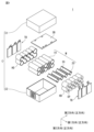
- FIG. 1 is a schematic exploded perspective view of a battery pack.
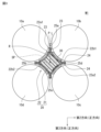
- FIG. 2 is a schematic perspective view of the heat absorbing member of the first embodiment.
- FIG. 3 is a schematic cross-sectional view of the battery module of the first embodiment.
- FIG. 4 is a schematic cross-sectional view of the battery module of the first embodiment when abnormal heat generation occurs.
- FIG. 5 is a schematic cross-sectional view of a battery module according to the second embodiment.
- FIG. 6 is a schematic cross-sectional view of the battery module of the second embodiment when abnormal heat generation occurs.
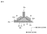
- FIG. 7A is a schematic cross-sectional view of a modified example of the heat-absorbing member of the second embodiment.
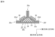
- FIG. 7B is a schematic cross-sectional view of a modified example of the heat-absorbing member of the second embodiment.
- FIG. 8A is a schematic perspective view of a modified example of the thermal expansion member.
- FIG. 8B is a schematic perspective view of a modified example of the thermal expansion member.
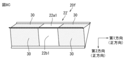
- FIG. 8C is a schematic perspective view of a modified example of the thermal expansion member.
- FIG. 9A is a schematic perspective view of a modified example of the thermal expansion member.
- FIG. 9B is a schematic perspective view of a modified example of the thermal expansion member.
- FIG. 9C is a schematic perspective view of a modified example of the thermal expansion member.
- the term "front view” refers to the state when an object (e.g., a battery pack) is placed and viewed from the front perpendicular to the thickness (height) direction, unless otherwise specified, and is synonymous with a front view.
- the front view refers to the state when viewed along the positive direction in the "second direction” shown in FIG. 2.
- positive direction refers to the directions of the first, second, and third arrows shown in the drawings
- the “negative direction” refers to the direction opposite to the first, second, and third arrows shown in the drawings.
- the first, second, and third directions are perpendicular to each other.
- the battery pack 1 includes a battery module M, a case C that houses the battery module M, a battery holder HD that holds and/or fixes the battery module M within the case C, and a tab TB that is electrically connected to the positive or negative electrode of the battery module M.
- the battery module M shown in FIG. 1 may include a battery module M1 of a first embodiment and a battery module M2 of a second embodiment, which will be described later.
- Case C may be composed of a first case C1 and a second case C2, and the first case C1 and the second case C2 may form a storage space for housing the battery module M.
- FIG. 1 illustrates a configuration in which the storage space is formed by two cases (the first case C1 and the second case C2), the present invention is not limited to this configuration, and the storage space may be composed of three or more cases.
- the case C may be made of any material, including a resin material (e.g., plastic) or a metal material.
- resin materials include polycarbonate resin (PC), acrylonitrile butadiene styrene resin (ABS), polybutylene terephthalate resin (PBT), modified polyphenylene ether resin (m-PPE), and polyamide resin (PA).
- metal materials include aluminum. From the perspective of more suitably housing the battery module M, it is preferable to use a material with high rigidity for the case C.
- the battery holder HD is a member that holds and/or fixes the battery module M (battery 10, heat absorption member 20, and thermal expansion member 30) within the storage space.
- the battery holder HD is provided on the positive and negative sides of the battery module M in the first direction.
- the battery holder HD holds and/or fixes the battery module M by fitting into the battery module M so as to sandwich it from both sides (positive and negative directions) in the first direction.
- the battery holder HD has an opening OP that exposes the positive and negative terminals of the battery 10 in the battery module M.
- the battery 10 (positive and negative terminals) is electrically connected to the tab TB through the opening OP.
- a pair of tabs TB are provided corresponding to the positive and negative terminals of the battery 10.
- the board SB can be driven by supplying power from the battery 10 to the board SB via the tabs TB.
- FIG. 2 is a schematic perspective view of a heat absorbing member according to the first embodiment
- Figure 3 is a schematic cross-sectional view of the battery module according to the first embodiment
- Figure 4 is a schematic cross-sectional view of the battery module according to the first embodiment when abnormal heat generation occurs.
- the battery module M1 includes a battery 10, a heat absorbing member 20, and a thermal expansion member 30.
- the battery is intended to be a chemical battery that mainly converts chemical energy into direct current power through a chemical reaction.
- the battery used in the battery pack 1 of the present embodiment is intended to be a cylindrical battery.
- the shape of the battery may be a shape other than a cylindrical shape (e.g., an elliptical cylinder, a rectangular column, a polygonal column, etc.).
- two or more batteries may be provided. Furthermore, the batteries may be arranged adjacent to each other. For example, in the embodiment shown in FIG. 3, four batteries 10a to 10d may be arranged adjacent to each other.
- the heat absorbing member 20 includes a heat absorbing agent 21 and a container 22 that contains the heat absorbing agent 21 (see FIG. 2).
- the heat absorbing member 20 may be provided at a position adjacent to the batteries 10a to 10d.
- the heat-absorbing agent 21 absorbs heat from the battery when the battery generates abnormal heat.
- the heat-absorbing agent 21 is mainly composed of a liquid such as water, and may contain gelling agents such as sodium polyacrylate (PNaAA), polyvinyl alcohol (PVA), polyhydroxyethyl methacrylate (PHE-MA), silicone hydrogel, and/or surfactant antifreeze agents.
- the container 22 is a member that contains the heat absorbing agent 21.
- the container 22 may be a columnar shape with a rectangular cross section.
- the term "rectangle shape" is not limited to a rectangular shape in the strict sense, but is intended to include a substantially rectangular shape having a configuration corresponding to four sides or four corners.
- the four corners may protrude from the sides, be rounded, or be flat, or the four sides may be curved and/or bent.
- Container 22 shown in FIG. 2 may have a first surface 22a1, a second surface 22b1, a first opposing surface 22a2 opposing first surface 22a1, and a second opposing surface 22b2 opposing second surface 22b1.
- opposing refers to the surfaces being positioned to face each other, but it also includes cases where the surfaces face each other in an inclined state, where the surfaces face each other in a curved state, and where the surfaces face each other in an inclined or curved state while a member is interposed between them.
- the term “opposing” may also refer to a relationship in which first opposing surface 22a2 is located on the opposite side of first surface 22a1.
- the first surface 22a1 may face the outer surface of one battery 10a of the four batteries 10a to 10d (see FIG. 3).
- the second surface 22b1 may face the outer surface of the other battery 10b of the four batteries 10a to 10d
- the first opposing surface 22a2 may face the outer surface of yet another battery 10c of the four batteries 10a to 10d
- the second opposing surface 22b2 may face the outer surface of yet another battery 10d of the four batteries 10a to 10d.
- the first surface 22a1, the second surface 22b1, the first opposing surface 22a2, and the second opposing surface 22b2 may each be along the outer circumferential surface of each battery 10a to 10d.
- the first surface 22a1, the second surface 22b1, the first opposing surface 22a2, and the second opposing surface 22b2 may be formed of a sheet-like member.
- the sheet-like member may have a resin layer 23.
- the first surface 22a1, the second surface 22b1, the first opposing surface 22a2, and the second opposing surface 22b2 may have their respective resin layers 23 bonded together by thermal fusion.
- the resin layer 23 may be a material capable of being thermally fused. Specifically, it may be unoriented polypropylene (CPP), biaxially oriented polypropylene (OPP), linear low density polyethylene (LLDPE), or biaxially oriented nylon (ONy).
- the container 22 may have a joint formed by joining the resin layers 23 to each other. Specifically, as shown in FIG. 3, the container 22 may have a first joint 25a where the resin layer 23 on one end side of the first surface 22a1 is joined to the resin layer 23 on one end side of the second surface 22b1, a second joint 25b where the resin layer 23 on the other end side of the first surface 22a1 is joined to the resin layer 23 on the other end side of the second opposing surface 22b2, a third joint 25c where the resin layer 23 on one end side of the first opposing surface 22a2 is joined to the resin layer 23 on one end side of the second opposing surface 22b2, and a fourth joint 25d where the resin layer 23 on the other end side of the second surface 22b1 is joined to the resin layer 23 on the other end side of the first opposing surface 22a2.
- the first joint 25a may be disposed in the inter-battery space SP between one battery 10a and the other battery 10b.
- the "inter-battery space” refers to the center position P of the straight line L where the distance between the one battery and the other battery is narrowest, and the area up to a position that is a radius R of the battery 10 away from the center position P (see FIG. 3).
- an example of the optimal position of the first joint 25a may be an extension of the straight line L where the distance between the one battery and the other battery is narrowest.
- the heat absorbing agent 21 can be attached to the battery at the location where heat is most easily transferred between the batteries (the location where the distance between the batteries is narrowest), thereby improving the heat absorption effect.
- the position of the first joint 25a may be disposed so as to overlap with the straight line L.
- the second joint 25b, the third joint 25c, and the fourth joint 25d may also be disposed in the inter-battery space between the two batteries.
- the thermal expansion member 30 is a member interposed between the batteries 10a to 10d and the heat absorption member 20.
- the thermal expansion member 30 may be provided between the battery 10a and the first surface 22a1, between the battery 10b and the second surface 22b1, between the battery 10c and the first opposing surface 22a2, and between the battery 10d and the second opposing surface 22b2.
- four thermal expansion members 30 may be provided corresponding to the four batteries.
- the thermal expansion member 30 provided between one battery 10a of the four batteries and the first surface 22a1 may be in contact with the outer circumferential surface of the battery 10a and the first surface 22a1.
- the thermal expansion member 30 provided between another battery 10b of the four batteries and the second surface 22b1 may be in contact with the outer circumferential surface of the battery 10b and the second surface 22b1.
- the thermal expansion member 30 provided between yet another battery 10c of the four batteries and the first opposing surface 22a2 may be in contact with the outer circumferential surface of the battery 10c and the first opposing surface 22a2.
- the thermal expansion member 30 provided between yet another battery 10d of the four batteries and the second opposing surface 22b2 may be in contact with the outer circumferential surface of the battery 10d and the second opposing surface 22b2.
- the position at which the thermal expansion member 30 is provided may be any position other than the first joint 25a to the fourth joint 25d.
- the material of the thermal expansion member 30 may be a material that expands when heat is applied.
- An example of such a material may include a resin material. More specifically, it may be chloroprene rubber or butyl rubber.
- Fig. 4 shows a case where abnormal heat generation occurs in one battery 10x among the four batteries.
- the abnormally heat-generating battery 10x When the abnormally heat-generating battery 10x (hereinafter referred to as the abnormally heat-generating battery) generates heat, heat is transferred to the thermal expansion member 30 in contact with the abnormally heat-generating battery 10x.
- the thermal expansion member 30 expands.
- stress due to the expansion of the thermal expansion member 30 acts on the surface of the container 22 facing the abnormally heat-generating battery 10x (second surface 22b1 in FIG. 4). Specifically, a stress is applied that presses the heat absorption agent 21 in the container 22 against the second surface 22b1.
- This stress causes the heat absorption agent 21 to be released from the first joint 25a between the second surface 22b1 and the first surface 22a1 and/or the fourth joint 25d between the second surface 22b1 and the first opposing surface 22a2.
- the released heat absorbing agent 21 then adheres to the abnormally heat generating battery 10x and the batteries 10a, 10c, and 10d surrounding the abnormally heat generating battery 10x, thereby absorbing the heat of the batteries.
- the expansion of the thermal expansion member 30 exerts a stress that presses the heat absorbing agent 21 in the container 22, allowing a greater amount of heat absorbing agent to be released outside the container. This reduces the amount of heat absorbing agent remaining in the container. In other words, the amount of heat absorbing agent that adheres to the battery can be increased. This makes it possible to further suppress the temperature rise of the battery.
- the expansion of the thermal expansion member 30 exerts a stress on the heat absorbing agent 21 in the container 22, pushing the heat absorbing agent 21 out of the container 22.
- the battery pack 1 of this embodiment includes the batteries 10a to 10d, the heat absorbing agent 21, the heat absorbing member 20 having the container 22 for accommodating the heat absorbing agent 21, and the thermal expansion member 30 interposed between the batteries 10a to 10d and the heat absorbing member 20 (see FIG. 3). Therefore, the heat expansion member 30 is expanded by the heat generation of the battery 10x, and the stress caused by the expansion acts on the heat absorbing member 20 to release the heat absorbing agent in the container to the outside of the container. This reduces the amount of heat absorbing agent remaining in the container. In other words, the amount of heat absorbing agent attached to the battery can be increased. Also, the heat absorbing agent in the container can be released to the outside of the container early. This allows the heat absorbing agent to adhere to the battery early. As a result, the heat absorbing agent adheres to the battery to cool the battery, and the temperature rise of the battery can be suppressed.
- the heat absorbing member 20 is provided in a position adjacent to the battery, the container 22 has a first surface 22a1 that faces the outer surface of the battery 10a, and the thermal expansion member 30 may be provided between the battery 10a and the first surface 22a1 (see FIG. 3).
- the thermal expansion member 30 is provided between the battery 10a and the first surface 22a1 that faces the outer surface of the battery 10a, the heat generated by the battery 10 is transferred to the thermal expansion member 30 via the outer surface of the battery 10, and the thermal expansion member 30 expands due to the transferred heat. Then, the stress caused by this expansion acts on the first surface 22a1 of the container 22, and the heat absorbing agent in the container can be released outside the container.
- the batteries are arranged so that the batteries 10a, 10b are adjacent to each other, the heat absorbing member 20 is provided at a position adjacent to the batteries 10a, 10b, the container 22 has a first surface 22a1 facing the outer surface of one battery 10a and a second surface 22b1 facing the outer surface of the other battery 10b, and the thermal expansion member 30 may be provided between the one battery 10a and the first surface 22a1 and between the other battery 10b and the second surface 22b1 (see FIG. 3).
- the thermal expansion member 30 is expanded by heat generated by at least one of the adjacent batteries 10a and 10b, and the stress caused by this expansion acts on the heat absorbing member 20 to release the heat absorbing agent in the container to the outside of the container.
- the batteries are cylindrical in shape, the first surface 22a1 is along the outer peripheral surface of one battery 10a, the second surface 22b1 is along the outer peripheral surface of the other battery 10b, the thermal expansion member 30 provided between one battery 10a and the first surface 22a1 is in contact with the outer peripheral surface of one battery 10a and the first surface 22a1, and the thermal expansion member 30 provided between the other battery 10b and the second surface 22b1 may be in contact with the outer peripheral surface of the other battery 10b and the second surface 22b1 (see Figure 3).
- the thermal expansion member 30 contacts the outer peripheral surface of one battery 10a and the first surface 22a1 that is shaped to fit the outer peripheral surface, and further contacts the outer peripheral surface of the other battery 10b and the second surface 22b1 that is shaped to fit the outer peripheral surface, so that heat generated in one battery and/or the other battery can be appropriately transferred to the thermal expansion member in contact with the battery. Furthermore, the stress caused by the expansion of the thermal expansion member 30 caused by heat generation can be appropriately applied to the first surface 22a1 and/or the second surface 22b1 that are in contact with the thermal expansion member 30, and the heat absorbing agent in the container can be released outside the container.
- the container 22 may have a resin layer 23 and a first joint 25a where the resin layer 23 on one end side of the first surface 22a1 and the resin layer 23 on one end side of the second surface 22b1 are joined (see FIG. 3).
- the container 22 since the container 22 has the first joint 25a where the resin layer 23 on one end side of the first surface 22a1 and the resin layer 23 on one end side of the second surface 22b1 are joined, when the thermal expansion member 30 expands due to heat generated by one battery 10a and/or the other battery 10b, stress due to the expansion is generated in the first joint 25a, and the first joint 25a is easily separated. As a result, the heat-absorbing agent in the container can be released from the first joint to the outside of the container.
- the first joint 25a may be disposed in the inter-battery space SP between one battery 10a and the other battery 10b (see FIG. 3). With this configuration, the heat absorbing agent 21 in the container 22 can be released from the first joint 25a disposed in the inter-battery space SP, and the heat absorbing agent can be effectively attached to both the one battery 10a and the other battery 10b, absorbing the heat of the batteries.
- the container 22 may further include a metal layer 24 (see FIG. 3). This configuration can reduce the moisture in the heat absorbing agent contained in the container from permeating through the container and evaporating.
- the container 22 further has a first opposing surface 22a2 opposing the first surface 22a1 and a second opposing surface 22b2 opposing the second surface 22b1, and may be provided with a second joint 25b at which the resin layer 23 on the other end side of the first surface 22a1 is joined to the resin layer 23 on the other end side of the second opposing surface 22b2, a third joint 25c at which the resin layer 23 on one end side of the first opposing surface 22a2 is joined to the resin layer 23 on one end side of the second opposing surface 22b2, and a fourth joint 25d at which the resin layer 23 on the other end side of the second surface 22b1 is joined to the resin layer 23 on the other end side of the first opposing surface 22a2 (see FIG. 3).
- the second joint 25b, the third joint 25c, and the fourth joint 25d provided between the surfaces are easily separated by the expansion of the thermal expansion member 30, so the heat absorbing agent inside the container can be released outside the container from at least one of the second to fourth joints.
- the thermal expansion member 30 may be provided at a position other than the first joint 25a. In another way, the thermal expansion member 30 may be provided at a position away from the first joint 25a. In yet another way, the thermal expansion member 30 may be provided at a position between the multiple joints 25. According to this configuration, since the thermal expansion member 30 is provided at a position other than the first joint 25a, the release of the heat absorbing agent from the first joint to the outside of the container is not hindered, and the heat absorbing agent in the container can be preferably released to the outside of the container.
- the container 22 may also be a columnar shape with a rectangular cross section. If the container 22 has a rectangular cross section, a heat absorbing agent can be attached to up to four batteries corresponding to the four sides of the rectangular shape for one heat absorption member 20 (container 22), and the heat of the batteries can be absorbed.
- the thermal expansion member 30 may also contain a resin material. If the thermal expansion member 30 contains a resin material, the thermal expansion member can be expanded suitably by applying heat to the resin material.
- FIG. 5 is a schematic cross-sectional view of the battery module according to the second embodiment
- Figure 6 is a schematic cross-sectional view of the battery module according to the second embodiment when abnormal heat generation occurs
- Figures 7A and 7B are schematic cross-sectional views of modified examples of the heat-absorbing member according to the second embodiment.
- a description of points in common with the configuration of the battery module M1 used in the battery pack 1 according to the first embodiment will be omitted as appropriate. In other words, the following description will focus on configurations that are different from those of the battery module M1 used in the battery pack 1 according to the first embodiment.
- the battery of this embodiment may be arranged such that two batteries 10a, 10b are adjacent to each other, for example, as shown in FIG.
- the container 22' of the heat absorbing member 20a of this embodiment may be a column shape having a triangular cross section, as shown in FIG. 5.
- the term "triangular shape” as used herein is not limited to a triangular shape in the strict sense, but is intended to include a substantially triangular shape having a configuration corresponding to three sides or three corners. For example, it may include a case where the three corners protrude from the sides, the three corners are rounded or flat, or the three sides are curved and/or bent.
- Container 22' of heat absorbing member 20a shown in FIG. 5 may have first surface 22a1, second surface 22b1, and third surface 22c.
- First surface 22a1, second surface 22b1, and third surface 22c may be formed by bending a sheet-like member. Specifically, the sheet-like member is bent so that the cross-sectional shape is triangular, and the resin layer 23 on one end side of first surface 22a1 and the resin layer 23 on one end side of second surface 22b1 are bonded.
- container 22' shown in FIG. 5 has a first bonding portion 25a where resin layer 23 on one end side of first surface 22a1 and resin layer 23 on one end side of second surface 22b1 are bonded.
- Fig. 6 shows a case where abnormal heat generation occurs in one of the two batteries, battery 10x.
- the expansion of the thermal expansion member 30 exerts a stress that presses the heat absorbing agent 21 in the container 22', allowing a greater amount of heat absorbing agent to be released outside the container. This reduces the amount of heat absorbing agent remaining in the container. In other words, the amount of heat absorbing agent that adheres to the battery can be increased. This makes it possible to further suppress the temperature rise of the battery.
- the battery module M2 shown in FIG. 5 has been described as having one joint (first joint 25a), but is not limited to this example.
- two sheet-like members may be joined to provide two joints (first joint 25a and first end joint 25e) in the heat absorption member 20b.
- the first surface 22a1 is formed by one sheet-like member
- the second surface 22b1 and the third surface 22c are formed by bending the other sheet-like member.
- the resin layer 23 on one end side of the third surface 22c is joined to the resin layer 23 on the other end side of the first surface 22a1.
- the 7A has, in addition to the first joint 25a, a first end joint 25e where the resin layer 23 on one end side of the third surface 22c is joined to the resin layer 23 on one end side of the first surface 22a1.
- the heat absorbing member 20b shown in FIG. 7A when the expansion of the thermal expansion member 30 due to heat generation from the battery acts on the container 22', the heat absorbing agent 21 is allowed to be released from the first end joint 25e in addition to the first joint 25a, so that the heat of the battery adjacent to the first end joint can be absorbed.
- three sheet-like members may be joined together to provide three joints (first joint 25a, first end joint 25e, and second end joint 25f) in heat absorbing member 20c.
- a sheet-like member constituting first surface 22a1, a sheet-like member constituting second surface 22b1, and a sheet-like member constituting third surface 22c are prepared.
- resin layer 23 on one end side of third surface 22c is joined to resin layer 23 on one end side of first surface 22a1
- resin layer 23 on the other end side of third surface 22c is joined to resin layer 23 on one end side of second surface 22b1.
- 7B has, in addition to the first joint 25a, a first end joint 25e where the resin layer 23 on one end side of the third surface 22c is joined to the resin layer 23 on the other end side of the first surface 22a1, and a second end joint 25f where the resin layer 23 on the other end side of the third surface 22c is joined to the resin layer 23 on one end side of the second surface 22b1.
- a first end joint 25e where the resin layer 23 on one end side of the third surface 22c is joined to the resin layer 23 on the other end side of the first surface 22a1
- a second end joint 25f where the resin layer 23 on the other end side of the third surface 22c is joined to the resin layer 23 on one end side of the second surface 22b1.
- At least one of the first joint 25a, the first end joint 25e, and the second end joint 25f may be disposed in the inter-battery space between one battery and the other battery (see Figs. 5 to 7B).
- the definition of the inter-battery space is as described above.
- the heat absorbing agent 21 in the container 22' can be released from at least one of the first joint 25a, the first end joint 25e, and the second end joint 25f to the outside of the container 22' (the area where the distance between the batteries is the shortest), and the heat absorbing agent 21 can be attached to both the one battery and the other battery, absorbing the heat of the batteries.
- the thermal expansion member 30 provided between one battery (not shown) and the first surface 22a1 may be provided on the entire surface of the first surface 22a1, and the thermal expansion member 30 provided between the other battery (not shown) and the second surface 22b1 may be provided on the entire surface of the second surface 22b1.
- the thermal expansion member 30 since the thermal expansion member 30 is provided on the entire surface of the first surface 22a1 and the entire surface of the second surface 22b1, the expansion area of the thermal expansion member 30 can be set relatively wide, and the effect on the heat absorption member due to expansion can be increased, and much of the heat absorbing agent in the container can be released outside the container.
- the thermal expansion member 30 may be provided on the entire surfaces of the first surface 22a1, the second surface 22b1, the first opposing surface 22a2, and the second opposing surface 22b2.
- the thermal expansion member 30 provided between one battery (not shown) and the first surface 22a1 may be provided on a portion of the first surface 22a1, and the thermal expansion member 30 provided between the other battery (not shown) and the second surface 22b1 may be provided on a portion of the second surface 22b1.
- the thermal expansion member 30 since the thermal expansion member 30 is provided on a portion of the first surface 22a1 and a portion of the second surface 22b1, stress due to expansion can be applied to the portion where the thermal expansion member is provided.
- the position where the heat absorbing agent 21 is released from the container 22' can be appropriately set in consideration of the heat generation mode of the battery.
- the thermal expansion member 30 can be partially provided at the position of the first surface 22a1 and the second surface 22b1 corresponding to the center part of the battery.
- a thermal expansion member 30 may be provided on the first surface 22a1, the second surface 22b1, the first opposing surface 22a2, and a portion of the second opposing surface 22b2.
- thermal expansion member 30 As a modified example of the thermal expansion member 30, as shown in the container 22' of the heat absorption member 20f shown in FIG. 8C, a plurality of thermal expansion members 30 are provided between one battery (not shown) and the first surface 22a1, and each thermal expansion member 30 is spaced apart from each other in the direction in which the central axis of the battery extends (first direction in FIG. 8C), and a plurality of thermal expansion members 30 are provided between the other battery (not shown) and the second surface 22b1, and each thermal expansion member 30 may be spaced apart from each other in the direction in which the central axis of the battery extends (first direction in FIG. 8C).
- the plurality of thermal expansion members 30 are spaced apart from each other in the direction in which the central axis of the battery extends (first direction in FIG. 8C), when the thermal expansion member 30 expands, the stress caused by the expansion acts so as to be sandwiched from both sides in the direction in which the central axis of the battery extends. Therefore, the heat absorption material can be effectively released outside the container.
- a plurality of thermal expansion members 30 may be provided on the first surface 22a1, the second surface 22b1, the first opposing surface 22a2, and the second opposing surface 22b2, and each thermal expansion member 30 may be spaced apart from each other in the direction in which the central axis of the battery extends (the first direction in FIG. 9C).
- the battery pack of the present disclosure includes the following aspects. ⁇ 1> A battery; A heat absorbing member having a heat absorbing agent and a container for accommodating the heat absorbing agent; a thermal expansion member interposed between the battery and the heat absorption member; A battery pack comprising: ⁇ 2> The heat absorbing member is provided adjacent to the battery, the container has a first surface facing an outer surface of the battery; The battery pack according to ⁇ 1>, wherein the thermal expansion member is provided between the battery and the first surface.
- the battery is arranged so that a plurality of the batteries are adjacent to each other, the heat absorbing member is provided adjacent to the plurality of batteries, the container has a first surface facing an outer surface of one battery and a second surface facing an outer surface of the other battery;
- the battery has a cylindrical shape, The first surface is along an outer circumferential surface of the one battery, The second surface is along an outer circumferential surface of the other battery, a thermal expansion member provided between the one battery and the first surface and in contact with the outer peripheral surface of the one battery and the first surface;
- the container has a resin layer, The battery pack according to ⁇ 4>, further comprising a first joint portion at which a resin layer on one end side of the first surface and a resin layer on one end side of the second surface are joined.
- ⁇ 6> The battery pack according to ⁇ 5>, wherein the first joint portion is disposed in an inter-battery space between the one battery and the other battery.
- ⁇ 7> The battery pack according to ⁇ 5> or ⁇ 6>, wherein the container further has a metal layer.
- the container has a resin layer, the container has a third surface having one end joined to the other end of the first surface and an other end joined to the other end of the second surface;
- the container has a resin layer and a metal layer provided on the outside of the resin layer, a first bonding portion at which a resin layer on one end side of the first surface and a resin layer on one end side of the second surface are bonded to each other, the container has a third surface having one end joined to one end of the first surface and another end joined to one end of the second surface; a first end joint portion at which a resin layer on one end side of the third surface and a resin layer on the other end side of the first surface are joined, a second end joint portion at which the resin layer on the other end side of the third surface and the resin layer on the other end side of the second surface are joined,
- the battery pack according to any one of ⁇ 4> to ⁇ 9>, wherein at least one of the first joint portion, the first end joint portion,
- the container is a first opposing surface opposing the first surface; a second opposing surface opposing the second surface, a second bonding portion at which a resin layer on the other end side of the first surface and a resin layer on the other end side of the second opposing surface are bonded to each other; a third bonding portion at which a resin layer on one end side of the first opposing surface and a resin layer on one end side of the second opposing surface are bonded to each other;
- the battery pack according to any one of ⁇ 5> to ⁇ 7>, further comprising: a fourth joint portion at which the resin layer on the other end side of the second surface and the resin layer on the other end side of the first opposing surface are joined.
- ⁇ 12> The battery pack according to any one of ⁇ 5> to ⁇ 7> and ⁇ 11>, wherein the thermal expansion member is provided at a position other than the first joint portion.
- ⁇ 13> The battery pack according to any one of ⁇ 1> to ⁇ 12>, wherein the container has a columnar shape with a triangular cross section.
- ⁇ 14> The battery pack according to any one of ⁇ 1> to ⁇ 12>, wherein the container has a columnar shape with a rectangular cross section.
- the thermal expansion member provided between the one battery and the first surface is provided on the entire surface of the first surface
- the thermal expansion member provided between the one battery and the first surface is provided on a portion of the first surface
- the battery pack according to any one of ⁇ 3> to ⁇ 14>, wherein the thermal expansion member provided between the other battery and the second surface is provided on a portion of the second surface.
- the thermal expansion member provided between the one battery and the first surface is provided in plurality, and each thermal expansion member is spaced apart from each other in a direction in which a central axis of the battery extends
- This disclosure can be used in battery packs that can more appropriately attach heat-absorbing agents to batteries that are abnormally hot.
Landscapes
- Chemical & Material Sciences (AREA)
- Chemical Kinetics & Catalysis (AREA)
- Electrochemistry (AREA)
- General Chemical & Material Sciences (AREA)
- Engineering & Computer Science (AREA)
- Manufacturing & Machinery (AREA)
- Secondary Cells (AREA)
- Battery Mounting, Suspending (AREA)
Priority Applications (1)
| Application Number | Priority Date | Filing Date | Title |
|---|---|---|---|
| JP2025545483A JPWO2025057529A1 (https=) | 2023-09-15 | 2024-06-27 |
Applications Claiming Priority (2)
| Application Number | Priority Date | Filing Date | Title |
|---|---|---|---|
| JP2023150373 | 2023-09-15 | ||
| JP2023-150373 | 2023-09-15 |
Related Child Applications (1)
| Application Number | Title | Priority Date | Filing Date |
|---|---|---|---|
| US19/436,780 Continuation US20260128450A1 (en) | 2023-09-15 | 2025-12-30 | Battery pack |
Publications (1)
| Publication Number | Publication Date |
|---|---|
| WO2025057529A1 true WO2025057529A1 (ja) | 2025-03-20 |
Family
ID=95021964
Family Applications (1)
| Application Number | Title | Priority Date | Filing Date |
|---|---|---|---|
| PCT/JP2024/023389 Pending WO2025057529A1 (ja) | 2023-09-15 | 2024-06-27 | 電池パック |
Country Status (2)
| Country | Link |
|---|---|
| JP (1) | JPWO2025057529A1 (https=) |
| WO (1) | WO2025057529A1 (https=) |
Citations (5)
| Publication number | Priority date | Publication date | Assignee | Title |
|---|---|---|---|---|
| JP2012252959A (ja) * | 2011-06-06 | 2012-12-20 | Mitsubishi Motors Corp | 組電池 |
| JP2013178966A (ja) * | 2012-02-28 | 2013-09-09 | Mitsubishi Heavy Ind Ltd | 電池モジュール |
| JP2018206605A (ja) * | 2017-06-05 | 2018-12-27 | 積水化学工業株式会社 | 熱暴走防止シート |
| US20220037715A1 (en) * | 2020-07-28 | 2022-02-03 | Sk Innovation Co., Ltd. | Multilayered firewall and battery pack comprising the same |
| WO2023132234A1 (ja) * | 2022-01-06 | 2023-07-13 | 株式会社村田製作所 | 電池パック |
-
2024
- 2024-06-27 JP JP2025545483A patent/JPWO2025057529A1/ja active Pending
- 2024-06-27 WO PCT/JP2024/023389 patent/WO2025057529A1/ja active Pending
Patent Citations (5)
| Publication number | Priority date | Publication date | Assignee | Title |
|---|---|---|---|---|
| JP2012252959A (ja) * | 2011-06-06 | 2012-12-20 | Mitsubishi Motors Corp | 組電池 |
| JP2013178966A (ja) * | 2012-02-28 | 2013-09-09 | Mitsubishi Heavy Ind Ltd | 電池モジュール |
| JP2018206605A (ja) * | 2017-06-05 | 2018-12-27 | 積水化学工業株式会社 | 熱暴走防止シート |
| US20220037715A1 (en) * | 2020-07-28 | 2022-02-03 | Sk Innovation Co., Ltd. | Multilayered firewall and battery pack comprising the same |
| WO2023132234A1 (ja) * | 2022-01-06 | 2023-07-13 | 株式会社村田製作所 | 電池パック |
Also Published As
| Publication number | Publication date |
|---|---|
| JPWO2025057529A1 (https=) | 2025-03-20 |
Similar Documents
| Publication | Publication Date | Title |
|---|---|---|
| JP6014752B2 (ja) | 安定性が向上した構造及び高い冷却効率性を有する電池モジュール | |
| US10700398B2 (en) | Cooling member and power storage module | |
| WO2023132234A1 (ja) | 電池パック | |
| KR101658517B1 (ko) | 냉각 부재를 활용한 전지모듈 | |
| JP2022551238A (ja) | 電池モジュールおよびこれを含む電池パック | |
| KR20150123102A (ko) | 이차전지용 배터리 셀 조립체 | |
| US11322784B2 (en) | Cooling member and power storage module | |
| JP2022550522A (ja) | 電池パックおよびその製造方法 | |
| JP2023501680A (ja) | 電池モジュールおよびこれを含む電池パック | |
| JP7394975B2 (ja) | 電池モジュール、これを含む電池パックおよび電池モジュール製造方法 | |
| JP2019520678A (ja) | 相変化物質を有するセルキャリヤ | |
| JP4553100B2 (ja) | 扁平型二次電池および組電池 | |
| WO2018034122A1 (ja) | 蓄電モジュール | |
| JP7584847B2 (ja) | 電池モジュールおよびこれを含む電池パック | |
| JP2023537017A (ja) | 電池モジュールおよびそれを含む電池パック | |
| JP6598026B2 (ja) | 蓄電モジュール | |
| JP7540844B2 (ja) | 電池モジュールおよびこれを含む電池パック | |
| JP7350419B2 (ja) | 電池モジュール、それを含む電池パックおよび電池モジュールの運搬方法 | |
| WO2025057529A1 (ja) | 電池パック | |
| JP6597519B2 (ja) | 蓄電モジュール | |
| US20260128450A1 (en) | Battery pack | |
| WO2018034132A1 (ja) | 冷却部材及び冷却部材を備えた蓄電モジュール | |
| WO2025074698A1 (ja) | 電池パック | |
| EP4465418B1 (en) | Battery pack provided with heat dissipation passive cooling structure | |
| WO2014103770A1 (ja) | 電池モジュール |
Legal Events
| Date | Code | Title | Description |
|---|---|---|---|
| 121 | Ep: the epo has been informed by wipo that ep was designated in this application |
Ref document number: 24865036 Country of ref document: EP Kind code of ref document: A1 |
|
| ENP | Entry into the national phase |
Ref document number: 2025545483 Country of ref document: JP Kind code of ref document: A |
|
| WWE | Wipo information: entry into national phase |
Ref document number: 2025545483 Country of ref document: JP |