WO2025057394A1 - プロセス処理装置の診断装置、診断システム、および診断方法 - Google Patents
プロセス処理装置の診断装置、診断システム、および診断方法 Download PDFInfo
- Publication number
- WO2025057394A1 WO2025057394A1 PCT/JP2023/033673 JP2023033673W WO2025057394A1 WO 2025057394 A1 WO2025057394 A1 WO 2025057394A1 JP 2023033673 W JP2023033673 W JP 2023033673W WO 2025057394 A1 WO2025057394 A1 WO 2025057394A1
- Authority
- WO
- WIPO (PCT)
- Prior art keywords
- component
- process processing
- diagnostic
- processing device
- deterioration
- Prior art date
- Legal status (The legal status is an assumption and is not a legal conclusion. Google has not performed a legal analysis and makes no representation as to the accuracy of the status listed.)
- Pending
Links
Images


Classifications
-
- G—PHYSICS
- G05—CONTROLLING; REGULATING
- G05B—CONTROL OR REGULATING SYSTEMS IN GENERAL; FUNCTIONAL ELEMENTS OF SUCH SYSTEMS; MONITORING OR TESTING ARRANGEMENTS FOR SUCH SYSTEMS OR ELEMENTS
- G05B23/00—Testing or monitoring of control systems or parts thereof
- G05B23/02—Electric testing or monitoring
- G05B23/0205—Electric testing or monitoring by means of a monitoring system capable of detecting and responding to faults
- G05B23/0218—Electric testing or monitoring by means of a monitoring system capable of detecting and responding to faults characterised by the fault detection method dealing with either existing or incipient faults
- G05B23/0224—Process history based detection method, e.g. whereby history implies the availability of large amounts of data
- G05B23/024—Quantitative history assessment, e.g. mathematical relationships between available data; Functions therefor; Principal component analysis [PCA]; Partial least square [PLS]; Statistical classifiers, e.g. Bayesian networks, linear regression or correlation analysis; Neural networks
-
- G—PHYSICS
- G05—CONTROLLING; REGULATING
- G05B—CONTROL OR REGULATING SYSTEMS IN GENERAL; FUNCTIONAL ELEMENTS OF SUCH SYSTEMS; MONITORING OR TESTING ARRANGEMENTS FOR SUCH SYSTEMS OR ELEMENTS
- G05B23/00—Testing or monitoring of control systems or parts thereof
- G05B23/02—Electric testing or monitoring
- G05B23/0205—Electric testing or monitoring by means of a monitoring system capable of detecting and responding to faults
- G05B23/0218—Electric testing or monitoring by means of a monitoring system capable of detecting and responding to faults characterised by the fault detection method dealing with either existing or incipient faults
- G05B23/0224—Process history based detection method, e.g. whereby history implies the availability of large amounts of data
- G05B23/0227—Qualitative history assessment, whereby the type of data acted upon, e.g. waveforms, images or patterns, is not relevant, e.g. rule based assessment; if-then decisions
- G05B23/0235—Qualitative history assessment, whereby the type of data acted upon, e.g. waveforms, images or patterns, is not relevant, e.g. rule based assessment; if-then decisions based on a comparison with predetermined threshold or range, e.g. "classical methods", carried out during normal operation; threshold adaptation or choice; when or how to compare with the threshold
-
- G—PHYSICS
- G05—CONTROLLING; REGULATING
- G05B—CONTROL OR REGULATING SYSTEMS IN GENERAL; FUNCTIONAL ELEMENTS OF SUCH SYSTEMS; MONITORING OR TESTING ARRANGEMENTS FOR SUCH SYSTEMS OR ELEMENTS
- G05B23/00—Testing or monitoring of control systems or parts thereof
- G05B23/02—Electric testing or monitoring
- G05B23/0205—Electric testing or monitoring by means of a monitoring system capable of detecting and responding to faults
- G05B23/0259—Electric testing or monitoring by means of a monitoring system capable of detecting and responding to faults characterized by the response to fault detection
- G05B23/0262—Confirmation of fault detection, e.g. extra checks to confirm that a failure has indeed occurred
-
- H—ELECTRICITY
- H10—SEMICONDUCTOR DEVICES; ELECTRIC SOLID-STATE DEVICES NOT OTHERWISE PROVIDED FOR
- H10P—GENERIC PROCESSES OR APPARATUS FOR THE MANUFACTURE OR TREATMENT OF DEVICES COVERED BY CLASS H10
- H10P50/00—Etching of wafers, substrates or parts of devices
- H10P50/20—Dry etching; Plasma etching; Reactive-ion etching
- H10P50/24—Dry etching; Plasma etching; Reactive-ion etching of semiconductor materials
- H10P50/242—Dry etching; Plasma etching; Reactive-ion etching of semiconductor materials of Group IV materials
Definitions
- the present invention relates to a diagnostic device, diagnostic system, and diagnostic method for a process processing device that processes semiconductor wafers.
- Process processing equipment is equipment that performs process processing to form fine shapes on semiconductor wafers.
- maintenance work such as replacing and cleaning components that require maintenance is usually performed periodically, based on the number of wafers processed, etc.
- unplanned maintenance work can occur due to deterioration of components due to aging or the accumulation of reaction by-products depending on the usage method.
- the diagnostic device for the process processing equipment first calculates feature quantities that indicate the characteristics of the sensor waveform data using sensor waveform data, which is a time-series signal consisting of multiple sensor items acquired sequentially for each process from multiple status sensors attached to the components of the process processing equipment (the data items of the sensor waveform data are called sensor items). Furthermore, based on the feature quantities, the deterioration level that indicates the deterioration state of the component is estimated from the deviation from the normal state, and the necessity for maintenance is determined by comparing with a preset alarm threshold, and an alarm is issued.
- sensor waveform data is a time-series signal consisting of multiple sensor items acquired sequentially for each process from multiple status sensors attached to the components of the process processing equipment (the data items of the sensor waveform data are called sensor items). Furthermore, based on the feature quantities, the deterioration level that indicates the deterioration state of the component is estimated from the deviation from the normal state, and the necessity for maintenance is determined by comparing with a preset alarm threshold, and an alarm is issued.
- Patent Document 1 states that "The anomaly detection device applies statistical modeling to a summary value that summarizes observed values, thereby inferring a state in which noise has been removed from the summary value, and generates a predicted value that predicts the summary value one period ahead based on the inference. The anomaly detection device detects the presence or absence of anomalies in the monitored equipment based on the predicted value.” Furthermore, Japanese Patent Application Laid-Open No.
- Patent Document 2 states that "A learning-type process anomaly diagnosis device that achieves accurate anomaly detection as well as anomaly diagnosis performance appropriate for practical process monitoring.” These prior art technologies are, so to speak, individual approaches that statistically process each sensor waveform data individually and estimate deterioration by comparing the predicted value with the current value.
- thresholds may be set by setting a management standard such as 3 ⁇ for the variation in the characteristic values of each sensor of each process processing device in the normal state.
- the process processing device is equipped with various sensors, and since they interfere with each other due to control and are affected by the device state, it is rare for the output of all sensor items to be stable. Therefore, when diagnosing deviations from the normal state for various sensor items, false alarms may occur frequently.
- thresholds are set based on sensor values when a degradation event occurs, the frequency of occurrence of degradation events is relatively low, making the setting itself difficult. In individual approach diagnosis such as Patent Documents 1 and 2, there is no recognition of issues regarding setting thresholds for degradation states corresponding to differences in devices and various sensor items.
- an object of the present invention is to provide a technology that, when diagnosing deterioration of a process processing device, suppresses false reports generated for components whose conditions are measured by multiple sensors or for each component of a group of process processing devices, and enables efficient countermeasures.
- one representative diagnostic device for a process processing device of the present invention is a diagnostic device for a process processing device that performs maintenance on components of the process processing device, and includes a feature change calculation unit that calculates a deterioration level corresponding to a change index from the feature levels of sensor waveform data of each sensor item for multiple sensors (a group of status sensors) that measure the status of the components, and a component deterioration level calculation unit that calculates a component deterioration level that corresponds one-to-one to the component using the multiple deterioration levels.
- FIG. 1 is a diagram showing the overall configuration of a process processing device and a diagnostic device for the process processing device.
- FIG. 2 is a relationship diagram showing the positioning of component deterioration levels and device common thresholds, etc.
- FIG. 3 is a flow chart showing an example of the flow of processing in the computer 30.
- FIG. 4 is a flowchart showing an example of the flow of processing in the server 50.
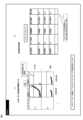
- FIG. 5 is a diagram for explaining an example of a method for setting a common threshold value for each device.
- FIG. 6 is a diagram showing an example of a display screen in the diagnosis result display unit 512. As shown in FIG.
- Process processing Equipment 1 is a diagram showing the overall configuration of a process processing device and a diagnostic device for the process processing device.
- the process processing device A (10), process processing device B (11), etc. constituting the process processing device group 1 in this embodiment process a wafer (sample 101) according to preset process processing conditions.
- Each process processing device is provided with the same type of components, and each component is provided with a status sensor group 102 consisting of a plurality of sensors that measure the status of the component, and the measured values of the sensor values (e.g., temperature and pressure) during processing or idle can be obtained as sensor waveform data.
- the process processing device, component, and status sensor include a plasma processing device, a microwave generation unit, and a current/voltage sensor, respectively.
- the diagnostic device 2 includes a group of computers (computers 30, 40, ...) including an execution unit 31 that acquires sensor waveform data corresponding to each process processing device in the process processing device group 1 and performs calculation processing, and a storage unit 32 that stores information required for the processing by the execution unit. Furthermore, the diagnostic device 2 includes a server 50 including an analysis unit 51 that sets the calculation conditions and device-common thresholds of the execution unit 31 and displays the diagnosis results, and a storage unit 52 that stores information required for the processing by the analysis unit 51.
- the process processing device group 1 is connected to the computer group (computer 30, computer 40, ...) directly or via a network.
- the computer group (computer 30, computer 40, ...) and server 50 are also connected via a network.
- the server 50 is also capable of setting calculation conditions and thresholds across the process processing device group 1 and analyzing and displaying diagnostic results.
- the connection between the computer group and server 50 is not necessarily limited to a network, and may be directly connected at the processing device.
- the execution unit 31 is composed of a processor such as a CPU or GPU, and includes a preprocessing unit 310, a feature amount change calculation unit 311, a diagnosis/alarm unit 312, a feature amount calculation unit 313, and a component deterioration level calculation unit 314, as described below.
- the storage unit 32 is composed of a memory, a hard disk, etc., and includes a sensor waveform storage unit 320 and a calculation result storage unit 321, as described below.
- the analysis unit 51 is composed of a processor such as a CPU or a GPU, and includes a calculation condition setting unit 510, an apparatus common threshold setting unit 511, and a diagnosis result display unit 512, as described below.
- the storage unit 52 is composed of a memory, a hard disk, etc., and includes a diagnosis result storage unit 520 and a maintenance time information storage unit 521, as described later.
- a process processing device has one or more components, and each component is provided with multiple sensors (a group of status sensors). One or more feature values are calculated for each sensor item of each sensor, and one or more deterioration degrees are calculated for each feature value. In this way, a component deterioration degree that has one-to-one correspondence with the component is calculated by calculation from multiple deterioration degrees obtained from one component. Further, a common threshold value for the devices, which serves as a criterion for deterioration detection, is set based on the component deterioration degree for the same type of components provided in a plurality of process processing devices (a group of process processing devices).
- Fig. 3 is a flow chart showing an example of a flow of a process in the computer 30.
- Fig. 3 shows a flow of a process for each diagnosis cycle.
- the diagnosis cycle may be, for example, for each process or for each fixed time interval.
- the computer 30 acquires sensor waveform data for a diagnostic period from the sensor waveform storage unit 320.
- the sensor waveform data is configured such that, for each of a plurality of sensor items, the sensor value is stored in a time series of processing time, time, etc.
- the pre-processing unit 310 selects one sensor item from the sensor waveform data (S1).
- the preprocessing unit 310 preprocesses the sensor waveform data of the selected sensor item (S2). Any method of preprocessing may be used, but for example, a process ID, which is information for identifying process conditions, may be used to specify a process ID to be used in diagnosis, and sensor waveform data associated with the process ID may be extracted.
- the processing time interval to be used in diagnosis may be extracted, and missing values may be removed and standardized to make the data easier to handle.
- the feature calculation unit 313 calculates a feature indicating the characteristics of the sensor waveform data using the preprocessed sensor waveform data (S3). As shown in Fig. 2, one or more feature values are calculated for each sensor item. For example, a statistical quantity such as the average value or standard deviation of the sensor waveform data can be used as the feature value. For example, in a plasma processing apparatus, the average value or the like in a specific time section can be used as the feature value for the waveform data of the current value. A feature value that is highly likely to be related to degradation may be calculated by checking against domain knowledge of the component, or multiple feature values may be calculated. Next, the feature amount change calculation unit 311 judges whether the initial state period has been exceeded (S4).
- S4 the initial state period has been exceeded
- the initial state period refers to a time interval from immediately after maintenance work on a component is performed until a certain period of time. If the initial state section has not been exceeded in the diagnosis cycle at the time of judgment, the preprocessing unit 310 judges whether the calculation of the feature quantities for all sensor items for which feature quantities are to be calculated has been completed (S6), and if so, the processing for this diagnosis cycle ends. If the calculation has not been completed in S6, the processing moves to the selection of another sensor item and continues.
- the feature amount change calculation unit 311 calculates the deterioration degree for each calculated feature amount by taking the change amount from the initial state (S5).
- the deterioration degree is calculated using multiple change indexes. Examples of the change index include the difference or ratio between the average value of the feature amount in the initial state section and the feature amount in the current diagnosis cycle, and the Mahalanobis distance between the feature amount in the initial state section and the feature amount in the current diagnosis cycle.
- the deterioration degree is defined based on the change amount from the initial state, so that the deterioration degree can be compared between the process processing devices.
- the change index to be compared depends on the sensor item, multiple change indexes are defined, and multiple deterioration degrees are calculated based on them. For example, if the change amount from the initial state is a significant physical quantity, the difference is considered to be effective as the change index, and if the rate of change is a significant physical quantity, the ratio is considered to be effective as the change index. In addition, if the feature amount has a large variation even in the initial state, the Mahalanobis distance considering the variation is considered to be effective.
- the component deterioration level calculation unit 314 proceeds to determine whether the calculation of the deterioration level for all sensor items has been completed (S7), and if not, the same process is repeated for the other sensor items, and if completed, the process proceeds to S8.
- the component deterioration degree calculation unit 314 calculates an index by integrating the deterioration degrees calculated for each component as a component deterioration degree. In addition, the contribution of each deterioration degree to the component deterioration degree is also calculated. Since the calculation conditions for the component deterioration degree are calculated in the calculation condition setting unit 510, an example of the calculation method will be described later. It is assumed that the deterioration of a component of a process processing device may be caused by multiple deterioration factors, or that even if there is a single deterioration factor, the deterioration state may affect multiple sensor items.
- the diagnosis/reporting unit 312 determines whether the calculation of the component deterioration level for all components to be diagnosed has been completed, and repeats the calculation until completion (S9).
- diagnosis and reporting unit 312 compares the device-common threshold value previously set for each component by the device-common threshold setting unit 511 with the value calculated for the component deterioration level in the current diagnosis cycle, and if the device-common threshold value is exceeded, notifies the server 50 of an alarm (S10).
- the series of calculation results calculated by the calculator 30 are stored in the calculation result storage unit 321.
- FIG. 4 is a flowchart showing an example of the flow of processing in the server 50.
- the processing flow for setting the calculation conditions and the device-common threshold value may be performed whenever it becomes necessary to set or update new calculation conditions or values of the device-common threshold value.
- the calculation result of the deterioration degree in the process processing device group 1 and the maintenance timing information for the component of interest are obtained from the calculation result storage unit 321 and the maintenance timing information storage unit 521, respectively (T1).
- the maintenance timing information includes history information such as the timing and content of maintenance performed due to deterioration of the components of each process processing device.
- the deterioration degree in the maintenance interval section is extracted from the time series trend of the deterioration degree calculated for each diagnostic period by the computer 30 based on the maintenance timing information (T2).
- T2 the maintenance timing information
- the left end of the time series trend of the deterioration degree represents the initial state
- the right end represents the deteriorated state. Since the deterioration degree is calculated multiple times by the computer 30, there are multiple time series trends of the deterioration degree.
- process processing devices that do not include maintenance timing information i.e., new process processing devices and process processing devices that are in use after maintenance (no deterioration events have occurred)
- the deterioration degree trend from the initial state to the latest calculation point is extracted. Since deterioration events occur relatively rarely, utilizing data from process processing devices that do not include maintenance timing information is effective in suppressing false reports.
- the calculation condition setting unit 510 calculates the component deterioration degree using the time series trends of the multiple deterioration degrees (T3).
- T3 time series trends of the multiple deterioration degrees
- a model for calculating the component deterioration degree can be constructed by applying a machine learning method including a decision tree structure.
- a model is constructed with each deterioration degree trend as an explanatory variable and the deterioration time as an objective variable, and the parameters of the model are optimized according to the data.
- a machine learning method having a feature amount selection function may be used to select one deterioration degree for each sensor item as shown in FIG.
- the common threshold setting unit 511 determines whether the calculation is complete for all process processing devices to be diagnosed, and repeats the process from T2 to T3 for the process processing devices to calculate the component deterioration degree of the component of interest (T4).
- the device-common threshold setting unit 511 sets a common threshold for each component degradation level in the process processing device group 1 (T5).
- FIG. 5 is a diagram for explaining an example of a device-common threshold setting method.
- FIG. 5 shows a state in which a time series trend of component degradation levels is calculated across the process processing device group 1.
- the set thresholds are comprehensively scanned, and a common threshold is set between devices such that the prediction accuracy index for the desired degradation time is maximized.
- the recall rate under conditions in which the matching rate is equal to or greater than a reference value is used as the prediction accuracy index.
- the component degradation level calculation model to be used for diagnosis by the computer 30 is selected based on the prediction accuracy index. In this way, a comprehensive approach in which a device-common threshold is set to optimize the prediction accuracy index makes it possible to suppress false reports caused by individual factors of the devices.
- the calculation condition setting unit 510 sets the selected component deterioration degree calculation model (calculation condition) and the inter-device common threshold as conditions to be used for diagnosis in the computer 30 (T6).
- the calculation condition setting unit 510 determines whether the settings have been completed for all components to be diagnosed, and repeats the processes from T1 to T6 (T7), after which the process ends.
- FIG. 6A and 6B are diagrams showing an example of a display screen in the diagnosis result display unit 512.
- the time series trends of the component deterioration degrees and the common thresholds between devices can be displayed for all components to be diagnosed in the process processing device group 1. This makes it possible to know at a glance which components of which process processing devices are closest to a deteriorated state. Furthermore, if an error of unknown cause occurs in a process processing device, efficient countermeasures can be taken by giving priority to the components closest to a deteriorated state as the maintenance work targets.
- Fig. 6(b) the contribution of each degradation level (degradation level calculation condition) to the component degradation level can be confirmed by specifying a component ID. This provides auxiliary information for factor estimation by checking against the domain knowledge of the component, enabling efficient countermeasures.
- the present invention is not limited to the above-mentioned embodiment, and various modifications are possible without departing from the spirit of the present invention.
- a configuration may be adopted in which the computer 30 performs part of the processing of the server 50.
- a diagnostic device for a process processing device for maintaining a component of the process processing device comprising: a feature amount change calculation unit that calculates a deterioration degree corresponding to a change index from feature amounts of sensor waveform data of each sensor item corresponding to a plurality of sensors (a group of status sensors) that measure the status of the component; a component degradation degree calculation unit that calculates a component degradation degree that has one-to-one correspondence with the component using a plurality of the degradation degrees;
- a diagnostic device for a process processing device comprising: (Aspect 2) The diagnostic device for a process processing device according to aspect 1, further comprising a diagnosis and reporting unit that performs diagnosis and reporting by comparing a common threshold value set among each component of a group of process processing devices with the component deterioration degree.
- (Aspect 3) The diagnostic device for a process processing device according to claim 1, wherein the feature amount change calculation unit uses, as the change index, at least one of a difference between the feature amount in a diagnostic cycle and an average value of a feature amount in an initial state section of the component (hereinafter referred to as an "initial feature amount"), a ratio to the average value of the initial feature amount, or a Mahalanobis distance to the average value of the initial feature amount.
- the component degradation degree calculation unit calculates the component degradation degree as a continuous probability value by using a method of applying a regression model including a decision tree structure.
- the diagnostic device for process processing equipment according to aspect 2 further comprising an equipment common threshold setting unit that sets the equipment common threshold by comprehensively searching for a prediction accuracy index of deterioration time from a time series trend of component deterioration degree in each component of the group of process processing equipment.
- the equipment common threshold setting unit uses a precision rate and a recall rate as the prediction accuracy index, and sets the equipment common threshold value so that the precision rate is equal to or greater than a reference value and the recall rate is maximized.
- the diagnostic device for a process processing device according to any one of aspects 2, 5, and 6, further comprising a diagnostic result display unit that displays a time series trend of a component deterioration degree in each component of the process processing device group and a contribution degree of the multiple deterioration degrees used in calculating the component deterioration degree.
- a diagnostic system for a process processing device for maintaining a component of the process processing device comprising: a feature amount change calculation unit that calculates a deterioration degree corresponding to a change index from feature amounts of sensor waveform data of each sensor item for a plurality of sensors (a group of status sensors) that measure the status of the component; a component degradation degree calculation unit that calculates a component degradation degree that has one-to-one correspondence with the component using a plurality of the degradation degrees;
- a diagnostic system for a process processing device comprising: (Aspect 9) The diagnostic system for process processing equipment according to aspect 8, further comprising a diagnostic and reporting unit that performs diagnosis and reporting by comparing the component deterioration degree with a common threshold value set among each component of a group of process processing equipment.
- a diagnostic method for a process processing device in which a component of the process processing device is a maintenance target comprising: a step of calculating a deterioration degree corresponding to a change index from a feature amount of each sensor waveform data item for a plurality of sensors (a group of status sensors) that measure the status of the component in a feature amount change calculation unit; a component degradation degree calculation unit calculating, in one-to-one correspondence with the component, a component degradation degree using a plurality of the degradation degrees;
- a diagnostic method for a process processing device comprising: (Aspect 11) The diagnostic method for a process processing device according to aspect 10, further comprising a step of diagnosing and issuing a report in a diagnostic/reporting unit by comparing the component deterioration degree with a common threshold value set among each component of a group of process processing devices.
Landscapes
- Physics & Mathematics (AREA)
- Engineering & Computer Science (AREA)
- General Physics & Mathematics (AREA)
- Automation & Control Theory (AREA)
- Artificial Intelligence (AREA)
- Evolutionary Computation (AREA)
- Mathematical Physics (AREA)
- Testing And Monitoring For Control Systems (AREA)
Priority Applications (5)
| Application Number | Priority Date | Filing Date | Title |
|---|---|---|---|
| KR1020247041272A KR20250040892A (ko) | 2023-09-15 | 2023-09-15 | 프로세스 처리 장치의 진단 장치, 진단 시스템, 및 진단 방법 |
| CN202380046757.1A CN120019342A (zh) | 2023-09-15 | 2023-09-15 | 工艺处理装置的诊断装置、诊断系统以及诊断方法 |
| PCT/JP2023/033673 WO2025057394A1 (ja) | 2023-09-15 | 2023-09-15 | プロセス処理装置の診断装置、診断システム、および診断方法 |
| JP2024572369A JPWO2025057394A1 (https=) | 2023-09-15 | 2023-09-15 | |
| TW113128281A TW202514853A (zh) | 2023-09-15 | 2024-07-30 | 製程處理裝置的診斷裝置、診斷系統及診斷方法 |
Applications Claiming Priority (1)
| Application Number | Priority Date | Filing Date | Title |
|---|---|---|---|
| PCT/JP2023/033673 WO2025057394A1 (ja) | 2023-09-15 | 2023-09-15 | プロセス処理装置の診断装置、診断システム、および診断方法 |
Publications (1)
| Publication Number | Publication Date |
|---|---|
| WO2025057394A1 true WO2025057394A1 (ja) | 2025-03-20 |
Family
ID=95021035
Family Applications (1)
| Application Number | Title | Priority Date | Filing Date |
|---|---|---|---|
| PCT/JP2023/033673 Pending WO2025057394A1 (ja) | 2023-09-15 | 2023-09-15 | プロセス処理装置の診断装置、診断システム、および診断方法 |
Country Status (5)
| Country | Link |
|---|---|
| JP (1) | JPWO2025057394A1 (https=) |
| KR (1) | KR20250040892A (https=) |
| CN (1) | CN120019342A (https=) |
| TW (1) | TW202514853A (https=) |
| WO (1) | WO2025057394A1 (https=) |
Citations (5)
| Publication number | Priority date | Publication date | Assignee | Title |
|---|---|---|---|---|
| WO2018061842A1 (ja) * | 2016-09-27 | 2018-04-05 | 東京エレクトロン株式会社 | 異常検知プログラム、異常検知方法および異常検知装置 |
| JP2018147385A (ja) * | 2017-03-08 | 2018-09-20 | 三菱日立パワーシステムズ株式会社 | 保守作業計画システム、保守作業計画方法及びプログラム |
| JP2021063706A (ja) * | 2019-10-11 | 2021-04-22 | 日本ユニシス株式会社 | プログラム、情報処理装置、情報処理方法及び学習済みモデルの生成方法 |
| WO2021241576A1 (ja) * | 2020-05-29 | 2021-12-02 | 株式会社ダイセル | 異常変調原因特定装置、異常変調原因特定方法及び異常変調原因特定プログラム |
| WO2023286142A1 (ja) * | 2021-07-13 | 2023-01-19 | 株式会社日立ハイテク | 診断装置及び診断方法並びにプラズマ処理装置及び半導体装置製造システム |
Family Cites Families (3)
| Publication number | Priority date | Publication date | Assignee | Title |
|---|---|---|---|---|
| JP2011258261A (ja) * | 2010-06-07 | 2011-12-22 | Mitsubishi Electric Corp | 劣化度判定装置及びコンピュータプログラム及び劣化度判定方法 |
| JP5259797B2 (ja) | 2011-09-05 | 2013-08-07 | 株式会社東芝 | 学習型プロセス異常診断装置、およびオペレータ判断推測結果収集装置 |
| KR102863239B1 (ko) * | 2022-02-07 | 2025-09-22 | 주식회사 히타치하이테크 | 진단 장치, 진단 방법, 반도체 제조 장치 시스템 및 반도체 장치 제조 시스템 |
-
2023
- 2023-09-15 WO PCT/JP2023/033673 patent/WO2025057394A1/ja active Pending
- 2023-09-15 CN CN202380046757.1A patent/CN120019342A/zh active Pending
- 2023-09-15 KR KR1020247041272A patent/KR20250040892A/ko active Pending
- 2023-09-15 JP JP2024572369A patent/JPWO2025057394A1/ja active Pending
-
2024
- 2024-07-30 TW TW113128281A patent/TW202514853A/zh unknown
Patent Citations (5)
| Publication number | Priority date | Publication date | Assignee | Title |
|---|---|---|---|---|
| WO2018061842A1 (ja) * | 2016-09-27 | 2018-04-05 | 東京エレクトロン株式会社 | 異常検知プログラム、異常検知方法および異常検知装置 |
| JP2018147385A (ja) * | 2017-03-08 | 2018-09-20 | 三菱日立パワーシステムズ株式会社 | 保守作業計画システム、保守作業計画方法及びプログラム |
| JP2021063706A (ja) * | 2019-10-11 | 2021-04-22 | 日本ユニシス株式会社 | プログラム、情報処理装置、情報処理方法及び学習済みモデルの生成方法 |
| WO2021241576A1 (ja) * | 2020-05-29 | 2021-12-02 | 株式会社ダイセル | 異常変調原因特定装置、異常変調原因特定方法及び異常変調原因特定プログラム |
| WO2023286142A1 (ja) * | 2021-07-13 | 2023-01-19 | 株式会社日立ハイテク | 診断装置及び診断方法並びにプラズマ処理装置及び半導体装置製造システム |
Also Published As
| Publication number | Publication date |
|---|---|
| CN120019342A (zh) | 2025-05-16 |
| TW202514853A (zh) | 2025-04-01 |
| KR20250040892A (ko) | 2025-03-25 |
| JPWO2025057394A1 (https=) | 2025-03-20 |
Similar Documents
| Publication | Publication Date | Title |
|---|---|---|
| CN107463161B (zh) | 预测飞行器中的故障的方法和系统以及监控系统 | |
| US10621545B2 (en) | Inventory management system having functions of performing inventory management and preventive maintenance | |
| US11796989B2 (en) | Monitoring system and monitoring method | |
| JP5284503B2 (ja) | 予測的状態監視のための診断システムおよび方法 | |
| TWI663510B (zh) | 設備保養預測系統及其操作方法 | |
| CN1862278A (zh) | 预测电动机剩余寿命的方法和系统 | |
| WO2020079860A1 (ja) | 機器故障診断支援システムおよび機器故障診断支援方法 | |
| JP5827426B1 (ja) | 予兆診断システム及び予兆診断方法 | |
| KR102108975B1 (ko) | 함정설비의 상태기반 정비 지원 장치 및 방법 | |
| JP2018113027A (ja) | プロセスの異常状態診断方法および異常状態診断装置 | |
| CN115222278B (zh) | 一种机器人智慧巡检的方法和系统 | |
| JP6915693B2 (ja) | システム分析方法、システム分析装置、および、プログラム | |
| CN101657770B (zh) | 使用间断检测的机器状况监测 | |
| JP6777142B2 (ja) | システム分析装置、システム分析方法、及び、プログラム | |
| JP7026012B2 (ja) | 機器状態監視システム及び機器状態監視方法 | |
| WO2025057394A1 (ja) | プロセス処理装置の診断装置、診断システム、および診断方法 | |
| CN120702731A (zh) | 识别机器的机械损伤的计算机实现的方法和状态监测装置 | |
| CN115345190A (zh) | 信号异常的检测方法、装置及服务器 | |
| CN119780564A (zh) | 一种基于数据融合的电力设备故障监测方法与设备 | |
| KR102863239B1 (ko) | 진단 장치, 진단 방법, 반도체 제조 장치 시스템 및 반도체 장치 제조 시스템 | |
| KR102797798B1 (ko) | 진단 장치 및 진단 방법 그리고 플라스마 처리 장치 및 반도체 장치 제조 시스템 | |
| CN117272844A (zh) | 配电盘工作寿命的预测方法及系统 | |
| WO2026023028A1 (ja) | 半導体製造装置の診断装置、診断システム、および診断方法 | |
| JP7708150B2 (ja) | 異常監視方法及び異常監視装置 | |
| TW202605530A (zh) | 半導體製造裝置的診斷裝置、診斷系統及診斷方法 |
Legal Events
| Date | Code | Title | Description |
|---|---|---|---|
| ENP | Entry into the national phase |
Ref document number: 2024572369 Country of ref document: JP Kind code of ref document: A |
|
| WWE | Wipo information: entry into national phase |
Ref document number: 2024572369 Country of ref document: JP |
|
| WWE | Wipo information: entry into national phase |
Ref document number: 202380046757.1 Country of ref document: CN |
|
| WWP | Wipo information: published in national office |
Ref document number: 1020247041272 Country of ref document: KR |
|
| 121 | Ep: the epo has been informed by wipo that ep was designated in this application |
Ref document number: 23952283 Country of ref document: EP Kind code of ref document: A1 |
|
| WWP | Wipo information: published in national office |
Ref document number: 202380046757.1 Country of ref document: CN |